Article

Towards Selective Laser Melting of High-Density Tungsten

1
School of Mechanical Engineering, Shandong University of Technology, Zibo 255049, China
2
Weihai Multicrystal Tungsten & Molybdenum Technology Co., Ltd., Weihai 264200, China
3
Department of Mechanics and Engineering Science, College of Engineering, Peking University, Beijing 100871, China
4
Beijing Advanced Innovation Center for Materials Genome Engineering, Institute for Advanced Materials and Technology, University of Science and Technology Beijing, Beijing 100083, China
5
Institute of Materials Intelligent Technology, Liaoning Academy of Materials, Shenyang 110004, China
*
Authors to whom correspondence should be addressed.
These authors contributed equally to this work.
Metals 2023, 13(8), 1431; https://doi.org/10.3390/met13081431
Submission received: 25 June 2023 / Revised: 24 July 2023 / Accepted: 3 August 2023 / Published: 10 August 2023
(This article belongs to the Section Additive Manufacturing)

Abstract

:
Selective laser melting (SLM) of tungsten (W) is challenging due to its high melting point and brittleness, resulting in defects including balling phenomenon, porosity and cracks. In this work, high-density crack-free SLM W was fabricated by employing cost-effective powders modified through air jet milling. The influence of the SLM processing parameters on microstructure, density, crack formation and the resulting mechanical properties of SLM W was investigated. Laser energy density and hatch distance were found to be the most important parameters in controlling porosity and crack formation of SLM W. The check-like microstructure in horizontal plane was induced by the difference in thermal gradients, which were caused by the movement of the heat source between overlapping regions and central regions of the molten pool. Combined efforts including powder modification through air jet milling, a 67° rotation scanning strategy, a hatch distance of 0.08 mm and a laser speed of 450 mm/s result in dense crack-free SLM W with relative density of 99.3%, microhardness of 403 HV50, and bending strength of 154 MPa. Additionally, the microstructure changed upon annealing at 1200 °C, accompanied by the reduced anisotropy of mechanical properties on both horizontal and vertical plane.

1. Introduction

Tungsten (W) has been applied to a wide range of fields, including microelectronic, aerospace, defense and nuclear energy, due to its high melting point, high strength, high thermal conductivity, high threshold energy for physical sputtering, and good stability at elevated temperatures [1]. W is also considered as one of the most promising candidate as plasma facing materials (PFMs), which require the material to competently withstanding intensive heat loads as well as enormous particle fluxes of hydrogen, helium and neutron [2,3,4]. Popular routes of manufacturing W are powder metallurgy [5,6,7] including pressureless sintering, hot isostatic pressing (HIP), spark plasma sintering (SPS) and thermo-mechanical processing [8,9,10,11,12] including hot rolling, hot forging and severe plastic deformation (SPD). However, sintering such refractory metal to full density is challenging and often results in residual porosity, which may significantly deteriorate the properties of materials. Additionally, these methods offer very limited sample geometry and the cost for processing scales up rapidly with the sample dimension.
Selective laser melting (SLM), one of the most hot-topic metal additive manufacturing techniques, offers unique possibilities for near-net-shape forming of the components with complex shapes [13,14,15,16,17]. However, SLM of W is still challenging due to its high melting point, high thermal conductivity and room-temperature brittleness, resulting in W parts with the balling phenomenon, porosity and cracks between fusion lines [18,19,20,21,22]. Most SLM W in the literature have low densities (<90% relative density). Enneti et al. [23] obtained a SLM W with relative density of 75% under energy density of 1000 J/mm3. Zhou et al. [20] applied a laser power of 200 W and obtained a sample with relative density of 82.9%. Another work by Zhang et al. [24] showed that insufficient laser power input could hardly melt W powder and resulted in a lack-of-fusion microstructure. On the other hand, some studies show that the optimized powders and the higher laser power are helpful to obtain denser parts [25,26,27,28,29]. Tan et al. [19] used spherical W powder prepared by radio-frequency induction plasma reactor and applied a laser power up to 370 W in the SLM process, resulting in a 98.5% relative density of W parts without significant balling or macrocracks. Wang et al. [25] also utilized spherical W powder and a laser power of 400 W, and obtained parts with 96% relative density. Given the adequate laser power input, some other densification defects, such as balling effects, macrocracks and warping phenomena that result from internal thermal stress could be minimized by tailoring other laser parameters specifically. Optimized laser parameters are of great significance in densification and crack avoidance of the SLM outcomes.
High-quality powders with good flowability, regular morphology and uniform size distribution are also prerequisites for SLM W parts [30,31,32,33,34,35]. Air jet milling (AJM) is a cost-effective way to prepare fluidizable spherical W powders with a uniform particle size distribution. AJM is a widely used technique in conventional powder metallurgy due to its ability to produce uncontaminated powders at a large-scale with a controllable narrow particle size distribution [36,37,38,39,40,41,42,43]. During the air jet milling process, the powder particles were forced by high speed and high purity nitrogen into the milling chamber, where the powders collided with each other, deagglomerated and morphologically modified. Monodisperse W powder with near-spherical shape could be obtained with optimized parameters. The prominent advantage of AJM reflects controlling particle size and oxygen content. Li et al. [43,44] investigated the fine grinding process of different particle size W powders prepared by air jet milling. The packing density of W powder with particle size of 3 μm was promoted by 49.3% after AJM. Furthermore, the deagglomeration and the collision of W powders might create new surface to enhance the sintering activity. Compared to the RF technology, the prominent advantage of AJM reflects controlling particle size and oxygen content, which is hopeful to solve the porosity, crack and balling phenomena.
In that context, we propose combined efforts including powder modifications and scanning strategy/parameter optimizations to address the challenges of producing high-density crack-free SLM W. In this work, raw W powder was air jet milled and successfully applied to SLM to obtain a dense part with density of 19.12 g/cm3 (99.3% theoretical density of W). This work exhibits a successful practice of applying economic AJM W powder to SLM, rather than other expensive spheroidization methods. Furthermore, this work highlights the critical processing parameters that are responsible for the improved microstructure and mechanical properties of SLM W, and the potential for further improvement through post-processing treatments such as annealing.

2. Experiment

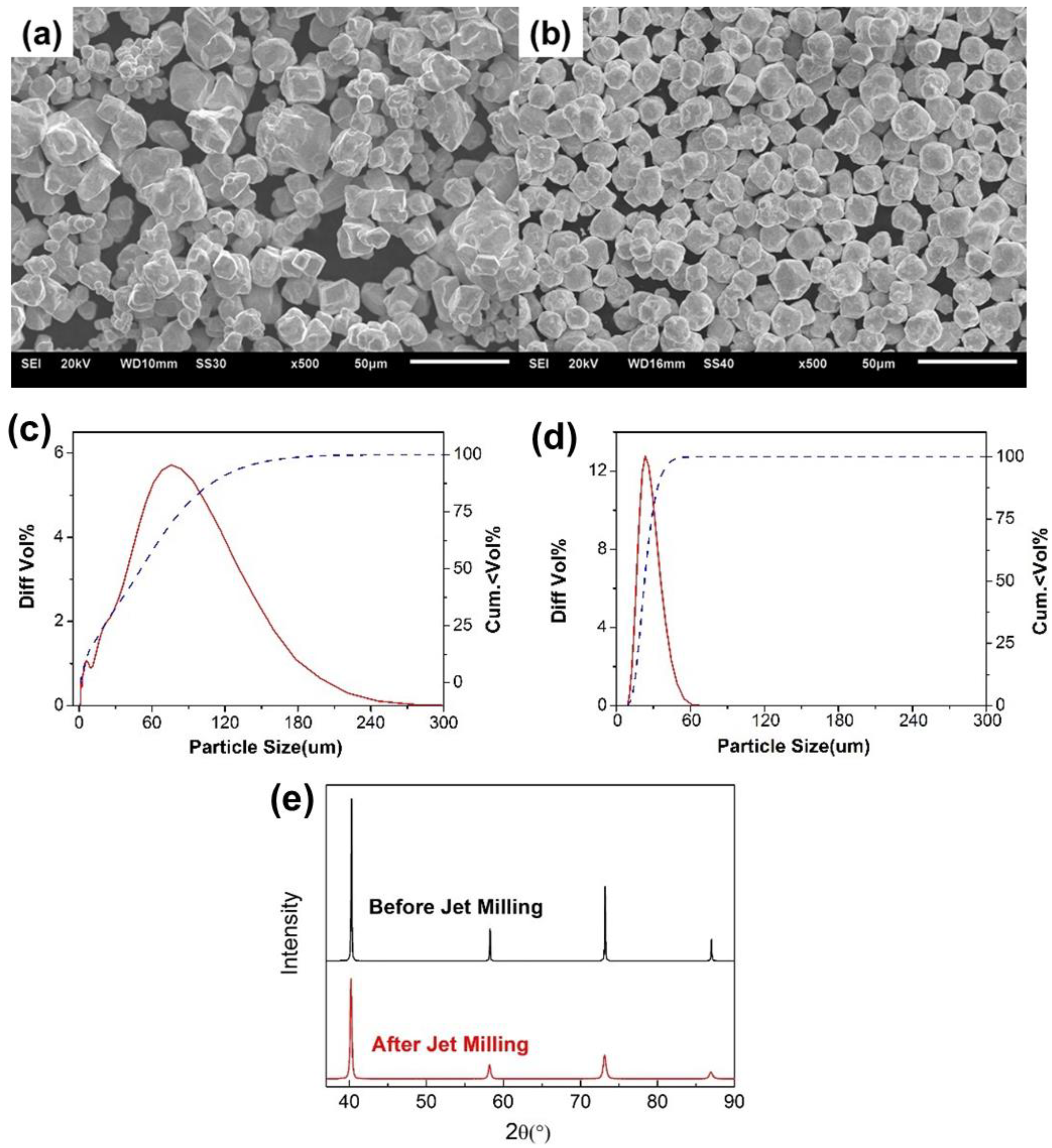
2.1. Powders and Air Jet Milling

The W powder was commercially available from Weihai Multicrystal Tungsten & Molybdenum Technology Co., Ltd. The air jet milling process was comminuted in high-purity nitrogen by QLMR-150T air jet mill equipped with a forced vortex classifier. The grinding process was determined by the operational parameters including the feed quantity, the grinding gas pressure and the rotating speed, which decide the classifier frequency. In the process, the feed mass was kept constant at 5 kg, the grinding pressure was set as 0.70 Mpa, and the rotating speed was set at the range of 2100–4200 rpm.

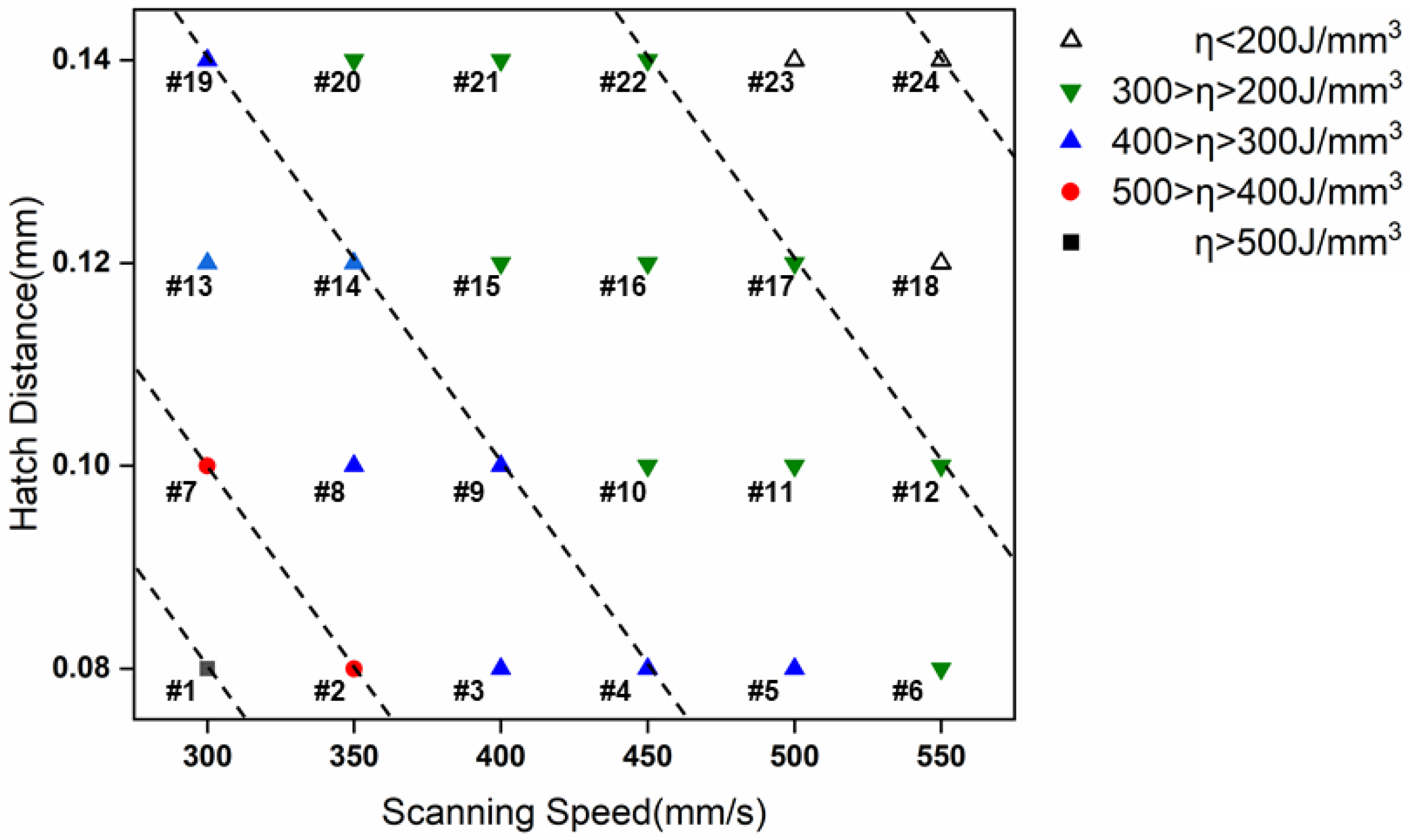
2.2. Selective Laser Melting Process

The air jet milled W powder was additively manufactured with a SLM Solutions 125 machine, equipped with a laser initiator with a laser power of up to 400 W. The laser spot is about 75 μm in diameter and the energy distribution complies with Gaussian distribution. In terms of laser parameters, the laser power and layer sickness were set as constants of 380 W and 0.03 mm, respectively, and the laser scanning speed was set as 300, 350, 400, 450, 500, 550 mm/s, and the hatch distance was set as 0.08, 0.1, 0.12, 0.14 mm. The details of the laser parameters are shown in Figure 1. The laser scanned in a stripe pattern, and the rotation angle between adjacent layers was set as 67° to minimize the residual stress. During the SLM process, the W powder was deposited on a 304 stainless steel substrate, which is conventionally considered an unsuitable material for wetting with W droplets. Our previous work has verified that insufficient wetting condition may lead to a severe locally warping of the W part off the substrate. However, we found that a longer waiting time between the adjacent W layers significantly declines the warping phenomenon. In this work, all of the experimental W specimens were free of warping under a waiting time of 180 s. Prior to the SLM process, the substrate was preheated to the machine’s maximum preheating temperature as 200 °C, and the chamber was charged with argon until the oxygen was discharged to a content level under 500 ppm. The argon gas flow was circulated inside the chamber during the whole process. The laser energy density (J/mm3), η, derives from the equation as below:
η = P s · t · d
where P is the laser power (W), s is scan speed (mm/s), t is layer thickness (mm) and d is hatch distance (mm) [45].

2.3. Characterization

The as-built W specimens were first applied to a density measurement with a helium pycnometer. All samples were cut from the central part of as-built specimens by electrical discharge machining (EDM) for density measurements. A theoretical density of 19.25 g/cm3 was chosen for W to calculate the relative density [1]. The surface and microstructural morphologies observations were performed using a JOEL scanning electron microscope. X-ray diffraction (XRD) was conducted using a Bruker D8 Advance Diffractometer (Karlsruhe, Germany) with Cu Kα radiation (wavelength, λ = 0.15418 nm), at 40 kV and 40 mA in a 2θ range of 30–90° using a step size of 0.02°. Electron backscattered diffraction (EBSD) was carried out on a Hitachi S-3400N SEM system (Tokyo, Japan) at 20 kV through an integrated Oxford/HKL EBSD detector, using a step size of 300 nm. Specimens for EBSD observation were grided by 2000# SiC sandpaper, mechanically polished by alumina suspension and then vibratorily polished for 5 h successively in order to remove any scratches and residual stress from the surface layer. The EBSD data was analyzed using Channel 5 software (HKL Technology, Inc., Connecticut, CA, USA). Micro-hardness of the specimens was measured by a Shimadzu HMV-2T micro Vickers tester (Tokyo, Japan) with a load of 50 gf for 10 s. All hardness indentations were applied to the polished horizontal (parallel to the build plate) surfaces, and an average value and corresponding standard deviation were estimated from 10 measurements. The as-built W component with the highest density was annealed at 1100 °C for 45 min in a hydrogen atmosphere to relieve the residual stress. A bending test was carried out on a universal testing machine controlled by computer. The specimen was cut into a 3 × 4 × 20 mm3 beam and then adopted to an ASTM E290-14 bending test. The bending strength was calculated as follows:
σ b = 3 F l 2 b d 2
where σ b is the bending stress (MPa), F is the load at the midpoint and b, d and l are the width, height and support span of the test beam, respectively.

3. Results and Discussion

3.1. Powder

Figure 2 shows the morphologies of W powders before and after air jet milling. Before air jet milling, the raw W powder was polyhedral and irregular in morphology. Some small powder is severely agglomerated and therefore results in the raw W powder with a wide range of particle size distribution. Meanwhile, the air jet milled W powder is deagglomerated to remove the satellite powder and shows a near-spherical shape. Compared with the powder before air jet milling, as shown in Figure 2c,d, a narrow particle size distribution of W powder is obtained after air jet milling. XRD result shown in Figure 2e reveals that W powder was free of contamination of other elements after jet milling.

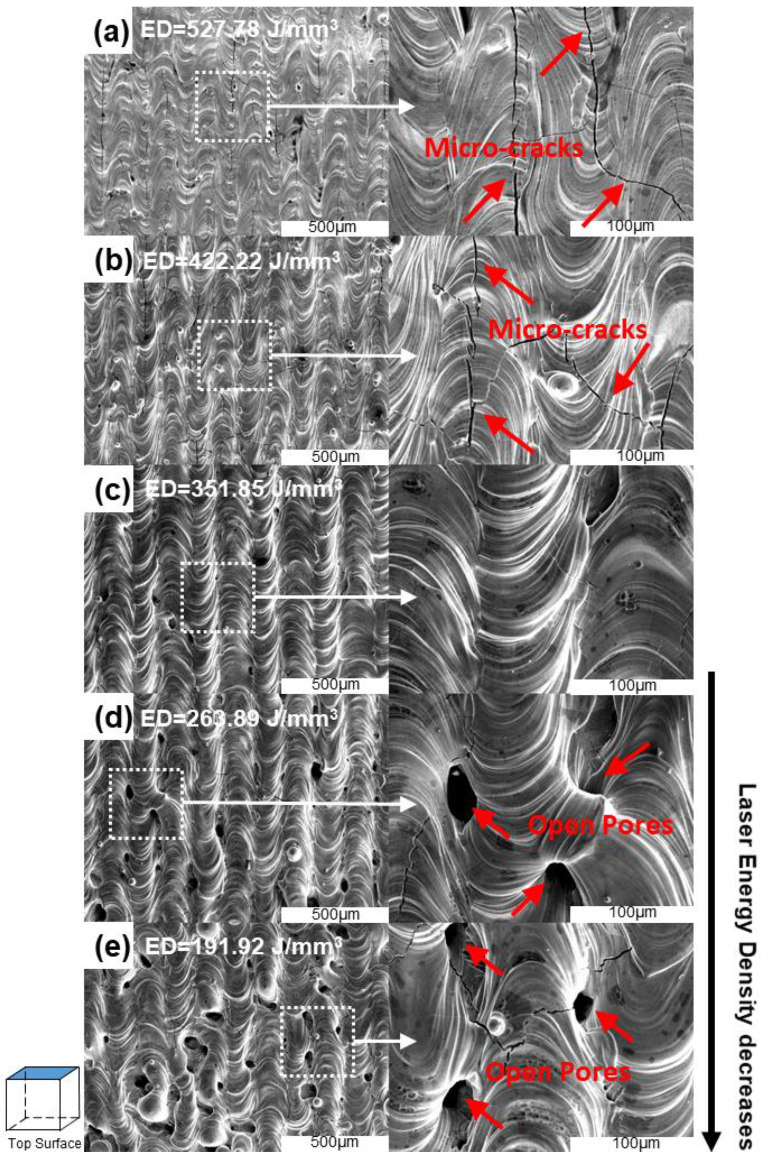
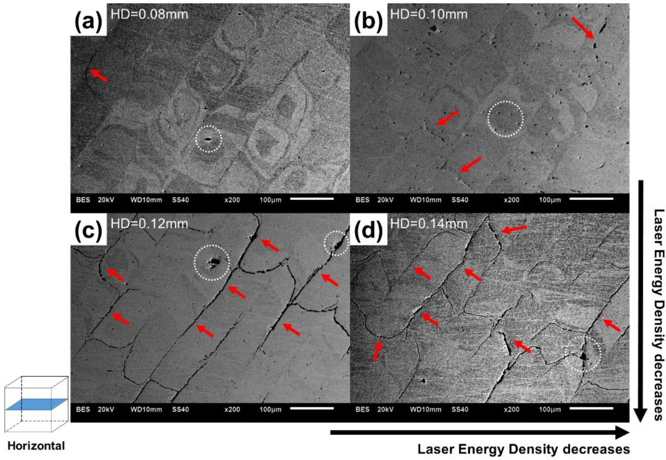
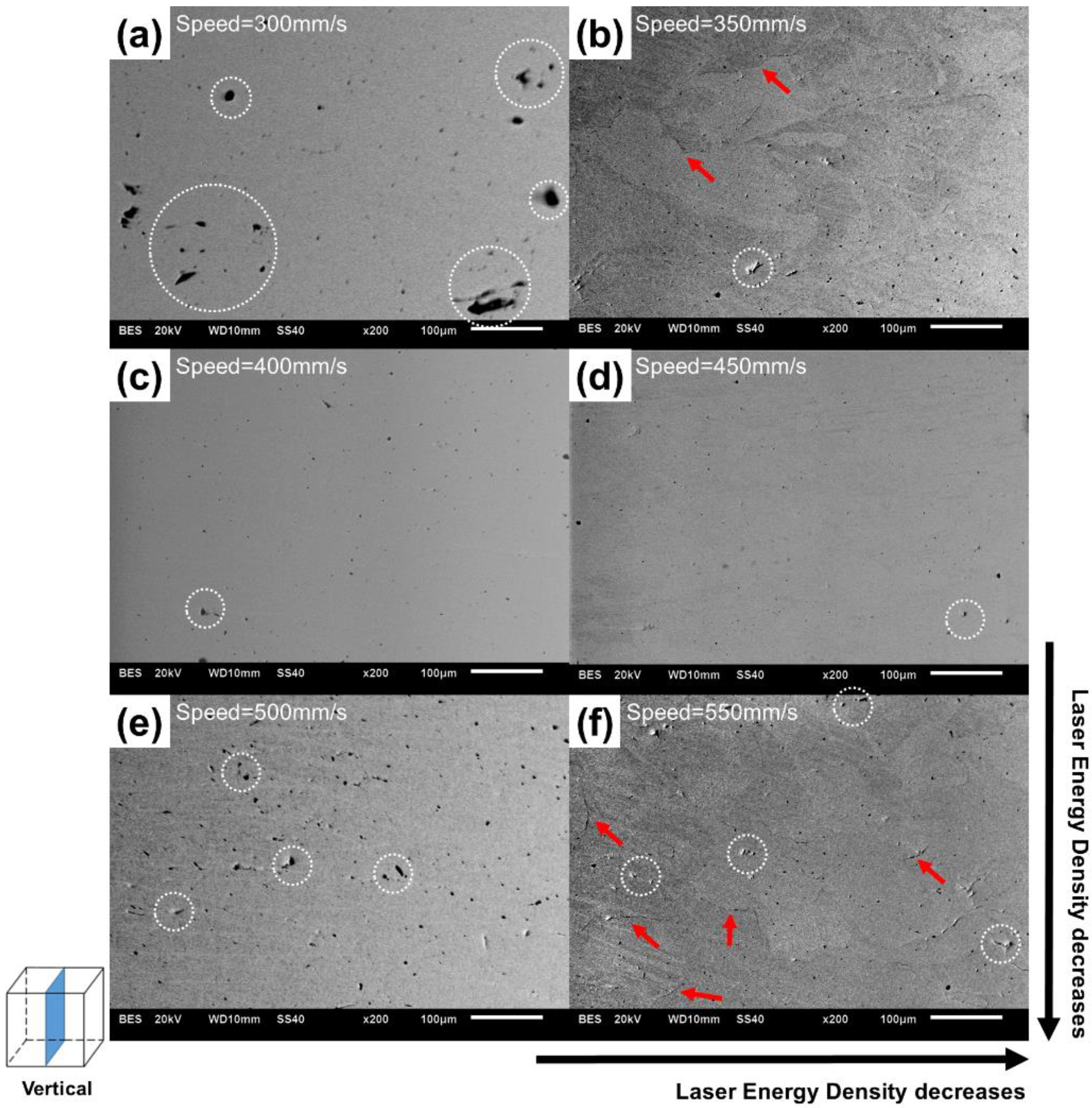
3.2. Density and Microstructure

The relationship between the laser energy density and the density of the corresponding component is shown in Figure 3. Laser energy density is a comprehensive parameter derived from the laser power, scanning speed, hatch distance and layer thickness. Three representative samples—#1 sample with the highest laser energy density of 527.78 J/mm3, #4 sample with a moderate energy density of 351.85 J/mm3, and #18 sample with the lowest laser energy density of 191.92 J/mm3, were analyzed on the morphologies of their top surfaces.
Figure 3 reveals that the #4 parameter leads to a denser component than any other parameter does, with a density that reaches 19.12 g/cm3, 99.3% of W’s theoretical density. Given the optimal #4 parameter, #4/#10/#16 samples as a set were subjected to a series of analyses to investigate the effect of the hatch distance on the densification of the W part, and the #1, #2, #3, #4, #5 and #6 samples as a set were analyzed to investigate the effect of laser speed on the densification outcome. The results are shown in Figure 4, Figure 5 and Figure 6.
Figure 4 reveals two main defects in the densification process of W part, i.e., the pores and the cracks. In the case of excessive laser energy input, the defect basically manifests as cracks in the fusion line, or sintering neck of W. Figure 4a,b shows that the excessive laser energy input is able to melt the powder completely, but the energy is too high to avoid cracks in the microstructure. This may result from the residual thermal stress introduced by the excessive laser energy. In the case of insufficient laser energy input, the defects are mainly presented as a balling phenomenon and big pores. Figure 4d,e shows that the insufficient laser energy input cannot completely melt the W powder, leading to severe balling and a lack of fusion phenomena. Balling phenomenon occurred when the as-melted W droplet was too quick in solidification to spread out completely. It can be observed in Figure 4d,e that more cracks form at the vicinity of voids. This means that, as a brittle metal, W suffers more from residual stresses or hot cracks induced by the voids that form in an unperfect SLM process [46]. The moderate laser energy input in Figure 4c could completely melt the powder and avoid severe cracks in the microstructure under the sound fusion of adjacent scanning lines. The scanning strategy with a 67° rotation angle between adjacent layers was also helpful to minimize the residual stress by generating the overlap of multi-directional molten pools, thus relieving the anisotropic stress accumulation from unidirectional melting and solidification. Simultaneously, this strategy can effectively reduce materials anisotropy in terms of microstructure [45,47,48]. Additionally, this study prolonged the waiting time between the adjacent layers, which meant the W sample was given adequate time to relieve the residual thermal stress after being exposed to high energy laser input. This significantly declined both the warping phenomenon and the development of micro-cracks.
Figure 5 and Figure 6 reveal a significant effect of laser parameters on the densification of the W parts. Figure 5 shows microstructures of selective laser melting W specimens with different laser hatch distance (HD). It is obvious that the crack in the microstructure increases severely with increasing laser hatch distance. Figure 5c,d, i.e., the HD = 0.12 mm and 0.14 mm sample, shows the large gap between the fusion line resulting from the lack of fusion, which should be avoided in the parameter optimization. On the contrary, the microstructure with HD = 0.08 mm shows no obvious crack and leads to the highest density.
Figure 6 exhibits the microstructures of selective laser melting W specimens with different laser speeds. It could be concluded that the laser speed 450 mm/s leads to the highest density, whereas higher or lower laser scanning speeds lead to the pores in the microstructure.

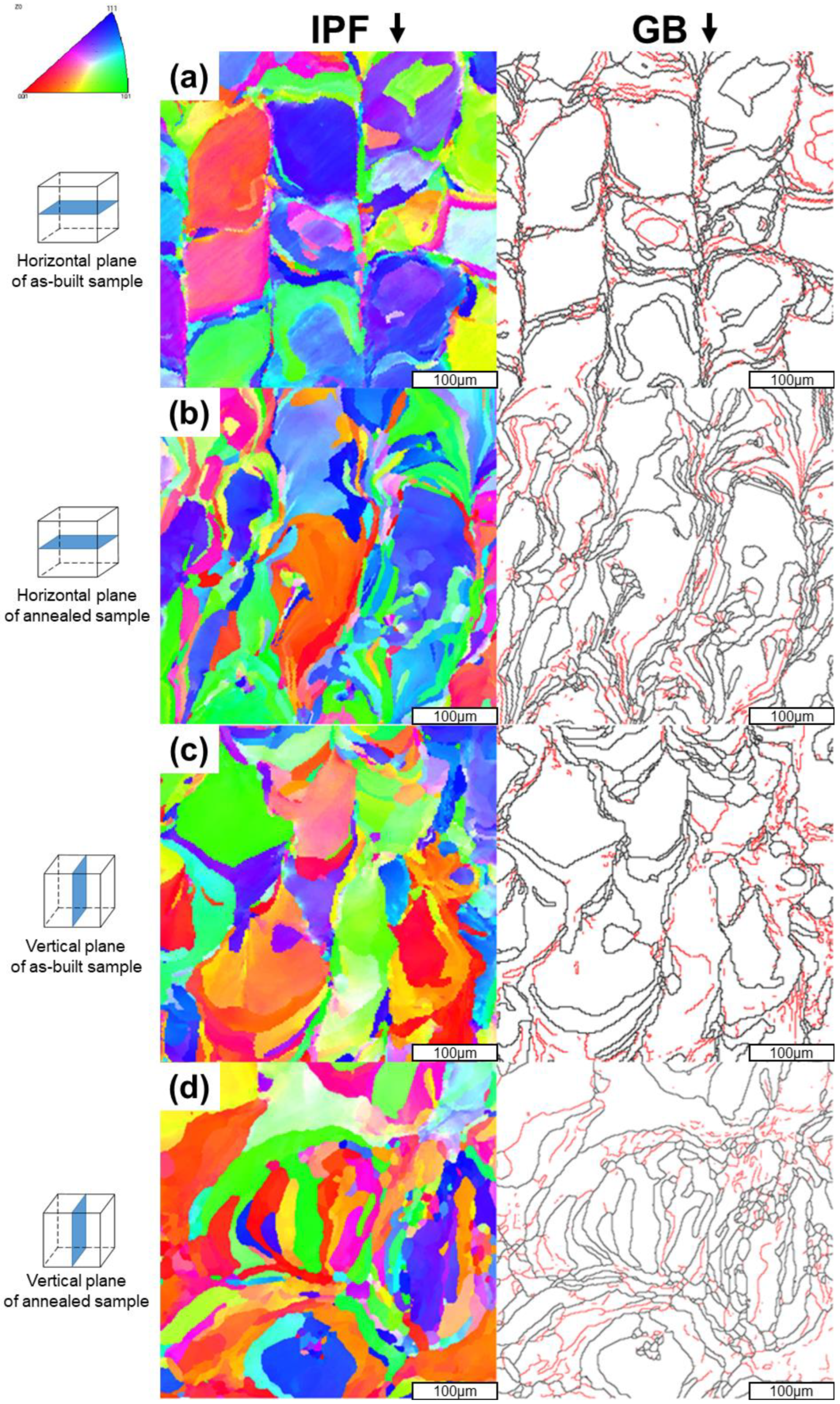
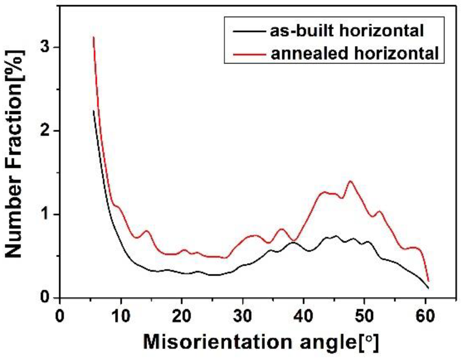
3.3. Grain Shape and Grain Boundaries

Figure 7 shows the EBSD results of the horizontal plane of SLM W part in as-built (hatch distance of 0.08 mm and laser speed of 450 mm/s) and annealed (at 1200 °C for 2 h) condition. The grains of the as-built specimen shown in Figure 7a exhibit the feature of a fusion line and a molten pool, while the grains of the annealed specimen shown in Figure 7c are more disordered in terms of grain shape, rather than the clear feature of fusion line and molten pool. This phenomenon shows the anisotropy of the as-built W was weakened after annealing. The mechanical properties shown in Table 1 reveal that the difference between the two values of the horizontal and lateral plane declined after annealing, which verifies the reduced material anisotropy after annealing.
Figure 7 also shows the grain shape of the horizontal plane of SLM W part in as-built and annealed condition. The IPF map of as-built specimen (Figure 7a) exhibit the feature of the fusion line and the molten pool, and “chessboard” shaped grains can be observed. The grain boundaries map (Figure 7b) shows that the distribution of HAGBs is parallel or perpendicular to the scanning direction, which essentially coincides with the melting line, while the red line refers to the LAGBs, which are mainly distributed in the area between the molten pools. Compared to the as-built specimen, the grain shape of the annealed specimen (Figure 7c) becomes more equiaxed, especially in the vertical plane. HAGBs originally coincident with the melting line become dispersed, which indicates a more refined microstructure (Figure 7d).
Due to the importance of grain boundaries for grain shape evolution and the dislocation motion, the misorientation angles of the grain boundaries are analyzed by their frequency, from 5° to 65°. The results are shown in Figure 8. Misorientation angles below 5° are not displayed. For high-angle grain boundaries (HAGBs, 15–65°), there is a correlation between the number fraction and the annealed condition. The annealed specimen shows a higher fraction of HAGBs than the as-built specimen. This difference cannot be observed for low-angle grain boundaries (LAGBs, 5–15°), where the annealed specimen shows the equivalent fraction of LAGBs with the as-built specimen.
This leads to the conclusion that, for SLM W, an annealed condition leads not only to a grain refinement and an increase in the overall number of grain boundaries, but to an increase in HAGBs. This can be associated with the recovery or recrystallization behavior during annealing. Dislocations move and gather to form at LAGBs and further induce coalescence of boundaries. As a result, the misorientation angle of boundaries constantly increases, which in turn leads to the transition from LAGBs to HAGBs.

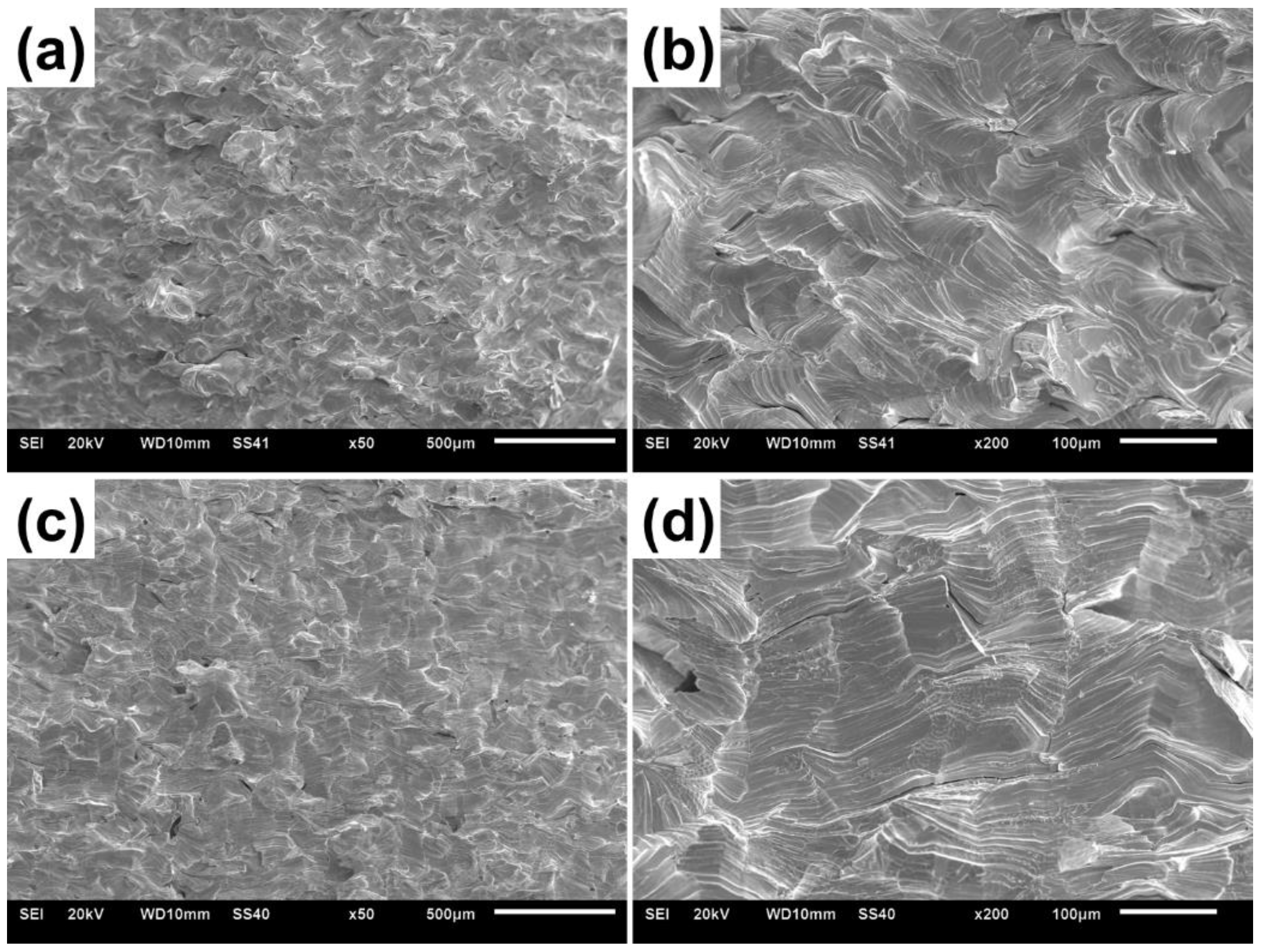
3.4. Mechanical Properties

Mechanical properties of the as-built and the annealed W produced by SLM in optimal conditions are listed in Table 1. The as-built sample shows obvious anisotropy in bending strength and Vickers hardness. Mechanical properties of the horizontal plane are much different with those of the vertical plane, whereas the annealed sample exhibits an approaching tendency of mechanical properties of the two planes. The reduced anisotropy of mechanical properties agrees well with the microstructure analysis in Figure 7.
In order to further investigate the fracture mechanism, representative bending fracture surfaces of the as-built and the annealed samples tested at ambient temperature are displayed in Figure 9. Only several near spherical pores are observed on the fracture surfaces. The as-built W predominantly undergoes transgranular fracture, and a few features of the intergranular fracture character is observed, as seen in Figure 9. Despite the most probably lower resistance of the grain boundaries, cleavage seems to be the preferred fracture type for the as-built W. A possible reason for this behavior could be the significantly increased dislocation density, which causes a pronounced subgrain structure. This might lead to a slightly textured microstructure which decreases the fracture resistance in this direction. Therefore, transgranular crack propagation occurs rather than major crack deviations to intergranular fracture. For transgranular fracture in untextured materials, it can be assumed that fracture occurs along {100} crack systems because these systems, the {100}<001> and <011>, have the lowest fracture toughness and would thus fracture preferentially. For the SLM-manufactured W, the presence of grain boundaries, orientation distribution of grains, and constraint imposed by the neighboring grains shows great influence on the fracture mode of W.
The fracture mode is much different from the intergranular fracture mode for the conventional powder metallurgy W, but is very similar with the deformed W. Compared to the powder metallurgy route, the melting process with much less impurity contamination improves the grain-to-grain bonding by physically creating clean boundaries. Additionally, the texture along the extrusion direction enables activation of the relatively high fracture toughness crack systems for transgranular fracture.
The grain boundaries in the SLM-manufactured W are significantly strengthened by the relatively high dislocation density induced by the high cooling rate. This will enhance the resistance to intergranular fracture. It is observed that the cleavage planes are mainly parallel to the longer axis of the grains. Cracks mainly propagate along the grain boundaries parallel to the longer axis of the grains. The reason for this behavior is most probably a significantly higher fracture resistance in the original crack propagation direction resulting from the orientation of the elongated grains. The fracture surface has a horizontal step-like character, and the fracture path appears tortuous. Smooth cleavage planes with striations are observed. The annealed sample also failed predominantly by transgranular fracture, and similar fracture surfaces consisting of cleavage planes with striations were observed. The surface appears as a stepped surface along the elongated grain direction. It is also reported that the elongated grain structure and the crack plane orientations of the manufactured samples play an important role in the crack propagation direction.

4. Conclusions

In this work, a pure W component with a relative density of 99.3% was successfully manufactured by selective laser melting. The effect of laser parameters on the densification process was discussed in detail. The mechanical properties of W parts in as-built and annealed conditions were tested. The conclusions are as follows.
(1)
The crack between the fusion line could be minimized by optimizing the laser parameter, including the laser scanning speed and hatch distance. Proper value of laser energy density results in a prior fusion outcome, rather than lack of fusion or cracking pattern. Combined efforts, including powders modification through air jet milling, 67° rotation scanning strategy, hatch distance of 0.08 mm and laser speed of 450 mm/s, lead to the higher density and less cracks;
(2)
The as-built W component was annealed to relive the residual stress, which homogenized the mechanical properties in the horizontal and vertical planes. EBSD results reveal the more equiaxed grain morphology and the reduced anisotropy, which are responsible for the homogenized mechanical properties. Bending strength is 155 MPa and 154 MPa in the horizontal and vertical plane, respectively. Vickers hardness is 402.7 HV and 396.4 HV in the horizontal and vertical plane, respectively.

Author Contributions

Conceptualization, H.Z.; methodology, D.W., X.L. (Xiaodong Li); writing—original draft preparation, H.Z., D.W.; investigation, X.L. (Xiaodong Li); data curation, D.W., X.L. (Xiaodong Li); writing—review & editing, X.L. (Xingyu Li), L.Z., F.Y., X.Q.; validation, L.Z., F.Y.; supervision, L.Z., F.Y., X.Q.; funding acquisition, L.Z., X.Q. All authors have read and agreed to the published version of the manuscript.

Funding

This research was funded by National Key R&D Program of China (no. 2022YFB3705400), National Natural Science Foundation of China (nos. 52074032, 51974029, 52071013, 52130407), Guangdong Basic and Applied Basic Re-search Foundation (no.2021B1515120033), 111 Project (no. B170003) and Basic and Applied Basic Research Fund of Guangdong Province (no. BK20BE015).

Data Availability Statement

The dataset presented in this article is not available yet.

Conflicts of Interest

The authors declare no conflict of interest.

References

  1. Lassner, E.; Schubert, W.D. Tungsten: Properties, Chemistry, Technology of the Element, Alloys and Chemical Compounds; Kluwer Academic and Plenum Publishers: New York, NY, USA, 1999; ISBN 0306450534. [Google Scholar]
  2. Linsmeier, C.; Rieth, M.; Aktaa, J.; Chikada, T.; Hoffmann, A.; Hoffmann, J.; Houben, A.; Kurishita, H.; Jin, X.; Li, M.; et al. Development of Advanced High Heat Flux and Plasma-Facing Materials. Nucl. Fusion 2017, 57, 092007. [Google Scholar] [CrossRef]
  3. Zinkle, S.J.; Busby, J.T. Structural Materials for Fission & Fusion Energy. Mater. Today 2009, 12, 12–19. [Google Scholar] [CrossRef]
  4. Philipps, V. Tungsten as Material for Plasma-Facing Components in Fusion Devices. J. Nucl. Mater. 2011, 415, S2–S9. [Google Scholar] [CrossRef]
  5. Li, X.; Zhang, L.; Dong, Y.; Gao, R.; Qin, M.; Qu, X.; Li, J. Pressureless Two-Step Sintering of Ultrafine-Grained Tungsten. Acta Mater. 2020, 186, 116–123. [Google Scholar] [CrossRef]
  6. Zhang, L.; Li, X.; Qu, X.; Qin, M.; Que, Z.; Wei, Z.; Guo, C.; Lu, X.; Dong, Y. Powder Metallurgy Route to Ultrafine-Grained Refractory Metals. Adv. Mater. 2023, 2205807. [Google Scholar] [CrossRef]
  7. Li, X.; Zhang, L.; Dong, Y.; Qin, M.; Wei, Z.; Que, Z.; Yang, J.; Qu, X.; Li, J. Towards Pressureless Sintering of Nanocrystalline Tungsten. Acta Mater. 2021, 220, 117344. [Google Scholar] [CrossRef]
  8. Li, X.; Zhang, L.; Wang, G.; Long, Y.; Yang, J.; Qin, M.; Qu, X.; So, K.P. Microstructure Evolution of Hot-Rolled Pure and Doped Tungsten under Various Rolling Reductions. J. Nucl. Mater. 2020, 533, 152074. [Google Scholar] [CrossRef]
  9. Mathaudhu, S.N.; DeRosset, A.J.; Hartwig, K.T.; Kecskes, L.J. Microstructures and Recrystallization Behavior of Severely Hot-Deformed Tungsten. Mater. Sci. Eng. A 2009, 503, 28–31. [Google Scholar] [CrossRef]
  10. Sheng, H.; Van Oost, G.; Zhurkin, E.; Terentyev, D.; Dubinko, V.I.; Uytdenhouwen, I.; Vleugels, J. High Temperature Strain Hardening Behavior in Double Forged and Potassium Doped Tungsten. J. Nucl. Mater. 2014, 444, 214–219. [Google Scholar] [CrossRef]
  11. Wei, Q.; Zhang, H.T.; Schuster, B.E.; Ramesh, K.T.; Valiev, R.Z.; Kecskes, L.J.; Dowding, R.J.; Magness, L.; Cho, K. Microstructure and Mechanical Properties of Super-Strong Nanocrystalline Tungsten Processed by High-Pressure Torsion. Acta Mater. 2006, 54, 4079–4089. [Google Scholar] [CrossRef]
  12. Ren, C.; Fang, Z.Z.; Koopman, M.; Butler, B.; Paramore, J.; Middlemas, S. Methods for Improving Ductility of Tungsten—A Review. Int. J. Refract. Met. Hard Mater. 2018, 75, 170–183. [Google Scholar] [CrossRef]
  13. Jia, H.; Sun, H.; Wang, H.; Wu, Y.; Wang, H. Scanning Strategy in Selective Laser Melting (SLM): A Review. Int. J. Adv. Manuf. Technol. 2021, 113, 2413–2435. [Google Scholar] [CrossRef]
  14. Yap, C.Y.; Chua, C.K.; Dong, Z.L.; Liu, Z.H.; Zhang, D.Q.; Loh, L.E.; Sing, S.L. Review of Selective Laser Melting: Materials and Applications. Appl. Phys. Rev. 2015, 2, 041101. [Google Scholar] [CrossRef]
  15. Wang, Z.; Ummethala, R.; Singh, N.; Tang, S.; Suryanarayana, C.; Eckert, J.; Prashanth, K.G. Selective Laser Melting of Aluminum and Its Alloys. Materials 2020, 13, 4564. [Google Scholar] [CrossRef]
  16. Karimi, J.; Suryanarayana, C.; Okulov, I.; Prashanth, K.G. Selective Laser Melting of Ti6Al4V: Effect of Laser Re-Melting. Mater. Sci. Eng. A 2021, 805, 140558. [Google Scholar] [CrossRef]
  17. Yan, X.; Chang, C.; Dong, D.; Gao, S.; Ma, W.; Liu, M.; Liao, H.; Yin, S. Microstructure and Mechanical Properties of Pure Copper Manufactured by Selective Laser Melting. Mater. Sci. Eng. A 2020, 789, 139615. [Google Scholar] [CrossRef]
  18. Zhang, B.; Li, Y.; Bai, Q. Defect Formation Mechanisms in Selective Laser Melting: A Review. Chin. J. Mech. Eng. 2017, 30, 515–527. [Google Scholar] [CrossRef] [Green Version]
  19. Tan, C.; Zhou, K.; Ma, W.; Attard, B.; Zhang, P.; Kuang, T. Selective Laser Melting of High-Performance Pure Tungsten: Parameter Design, Densification Behavior and Mechanical Properties. Sci. Technol. Adv. Mater. 2018, 19, 370–380. [Google Scholar] [CrossRef] [Green Version]
  20. Zhou, X.; Liu, X.; Zhang, D.; Shen, Z.; Liu, W. Balling Phenomena in Selective Laser Melted Tungsten. J. Mater. Process. Technol. 2015, 222, 33–42. [Google Scholar] [CrossRef]
  21. Gu, D.; Guo, M.; Zhang, H.; Sun, Y.; Wang, R.; Zhang, L. Effects of Laser Scanning Strategies on Selective Laser Melting of Pure Tungsten. Int. J. Extrem. Manuf. 2020, 2, 025001. [Google Scholar] [CrossRef]
  22. Fang, Z.-C.; Wu, Z.-L.; Huang, C.-G.; Wu, C.-W. Review on Residual Stress in Selective Laser Melting Additive Manufacturing of Alloy Parts. Opt. Laser Technol. 2020, 129, 106283. [Google Scholar] [CrossRef]
  23. Enneti, R.K.; Morgan, R.; Atre, S.V. Effect of Process Parameters on the Selective Laser Melting (SLM) of Tungsten. Int. J. Refract. Met. Hard Mater. 2018, 71, 315–319. [Google Scholar] [CrossRef]
  24. Zhang, D.; Cai, Q.; Liu, J. Formation of Nanocrystalline Tungsten by Selective Laser Melting of Tungsten Powder. Mater. Manuf. Process. 2012, 27, 1267–1270. [Google Scholar] [CrossRef]
  25. Wang, L.; Wu, J.; Zhang, D. Properties Evolution of Additive Manufacture Used Tungsten Powders Prepared by Radio Frequency Induction Plasma. Int. J. Refract. Met. Hard Mater. 2017, 67, 90–97. [Google Scholar] [CrossRef]
  26. Sun, H.; Hohl, B.; Cao, Y.; Handwerker, C.; Rushing, T.S.; Cummins, T.K.; Weiss, J. Jet Mill Grinding of Portland Cement, Limestone, and Fly Ash: Impact on Particle Size, Hydration Rate, and Strength. Cem. Concr. Compos. 2013, 44, 41–49. [Google Scholar] [CrossRef]
  27. Ding, W.; Tao, Q.; Chen, J.; Chen, G.; Qu, X.; Qin, M. Enhanced Mechanical Properties by Laser Powder Bed Fusion Using Cost-Effective Hydride-Dehydride Titanium Powders. J. Mater. Process. Technol. 2023, 313, 117887. [Google Scholar] [CrossRef]
  28. Tao, Q.; Ding, W.; Chen, G.; Qu, X.; Han, L.; Qin, M. Effect of Jet Milling on HDH CP-Ti Powders: Microstructure and Properties. JOM 2021, 73, 3102–3110. [Google Scholar] [CrossRef]
  29. Tao, Q.; Wang, Z.; Chen, G.; Cai, W.; Cao, P.; Zhang, C.; Ding, W.; Lu, X.; Luo, T.; Qu, X.; et al. Selective Laser Melting of CP-Ti to Overcome the Low Cost and High Performance Trade-Off. Addit. Manuf. 2020, 34, 101198. [Google Scholar] [CrossRef]
  30. Rajabi, M.; Simchi, A.; Vahidi, M.; Davami, P. Effect of Particle Size on the Microstructure of Rapidly Solidified Al–20Si–5Fe–2X (X=Cu, Ni, Cr) Powder. J. Alloys Compd. 2008, 466, 111–118. [Google Scholar] [CrossRef]
  31. Spierings, A.B.; Voegtlin, M.; Bauer, T.; Wegener, K. Powder Flowability Characterisation Methodology for Powder-Bed-Based Metal Additive Manufacturing. Prog. Addit. Manuf. 2016, 1, 9–20. [Google Scholar] [CrossRef]
  32. Sames, W.J.; List, F.A.; Pannala, S.; Dehoff, R.R.; Babu, S.S. The Metallurgy and Processing Science of Metal Additive Manufacturing. Int. Mater. Rev. 2016, 61, 315–360. [Google Scholar] [CrossRef]
  33. Mussatto, A.; Groarke, R.; O’Neill, A.; Obeidi, M.A.; Delaure, Y.; Brabazon, D. Influences of Powder Morphology and Spreading Parameters on the Powder Bed Topography Uniformity in Powder Bed Fusion Metal Additive Manufacturing. Addit. Manuf. 2021, 38, 101807. [Google Scholar] [CrossRef]
  34. Strondl, A.; Lyckfeldt, O.; Brodin, H.; Ackelid, U. Characterization and Control of Powder Properties for Additive Manufacturing. JOM 2015, 67, 549–554. [Google Scholar] [CrossRef]
  35. Wang, L.; Yu, A.; Li, E.; Shen, H.; Zhou, Z. Effects of Spreader Geometry on Powder Spreading Process in Powder Bed Additive Manufacturing. Powder Technol. 2021, 384, 211–222. [Google Scholar] [CrossRef]
  36. Yang, Y.; Ding, J. Microwave Property of Micron and Sub-Micron Fe90Al10 Flakes Fabricated via Ball Milling and Jet Milling Routes. J. Alloys Compd. 2012, 528, 58–62. [Google Scholar] [CrossRef]
  37. Ghambari, M.; Emadi Shaibani, M.; Eshraghi, N. Production of Grey Cast Iron Powder via Target Jet Milling. Powder Technol. 2012, 221, 318–324. [Google Scholar] [CrossRef] [Green Version]
  38. Rama Rao, N.V.; Hadjipanayis, G.C. Influence of Jet Milling Process Parameters on Particle Size, Phase Formation and Magnetic Properties of MnBi Alloy. J. Alloys Compd. 2015, 629, 80–83. [Google Scholar] [CrossRef]
  39. Protonotariou, S.; Ritzoulis, C.; Mandala, I. Jet Milling Conditions Impact on Wheat Flour Particle Size. J. Food Eng. 2021, 294, 110418. [Google Scholar] [CrossRef]
  40. Lu, X.; Liu, C.; Zhu, L.; Qu, X. Influence of Process Parameters on the Characteristics of TiAl Alloyed Powders by Fluidized Bed Jet Milling. Powder Technol. 2014, 254, 235–240. [Google Scholar] [CrossRef]
  41. Kushimoto, K.; Suzuki, K.; Ishihara, S.; Soda, R.; Ozaki, K.; Kano, J. Analysis of the Particle Collision Behavior in Spiral Jet Milling. Adv. Powder Technol. 2023, 34, 103993. [Google Scholar] [CrossRef]
  42. Dhakate, M.M.; Venkatraman, A.; Khakhar, D.V. Breakage of a Single Particle in an Air Jet Mill. ACS Eng. Au 2023. [Google Scholar] [CrossRef]
  43. Li, R.; Qin, M.; Liu, C.; Chen, Z.; Wang, X.; Qu, X. Particle Size Distribution Control and Related Properties Improvements of Tungsten Powders by Fluidized Bed Jet Milling. Adv. Powder Technol. 2017, 28, 1603–1610. [Google Scholar] [CrossRef]
  44. Li, R.; Qin, M.; Liu, C.; Huang, H.; Lu, H.; Chen, P.; Qu, X. Injection Molding of Tungsten Powder Treated by Jet Mill with High Powder Loading: A Solution for Fabrication of Dense Tungsten Component at Relative Low Temperature. Int. J. Refract. Met. Hard Mater. 2017, 62, 42–46. [Google Scholar] [CrossRef]
  45. Shanmuganathan, P.K.; Purushothaman, D.B.; Ponnusamy, M. Effect of High Laser Energy Density on Selective Laser Melted 316L Stainless Steel: Analysis on Metallurgical and Mechanical Properties and Comparison with Wrought 316L Stainless Steel. 3D Print. Addit. Manuf. 2023, 10, 383–392. [Google Scholar] [CrossRef]
  46. Vivek, R.; Prakash, B.; Sivamani, S.; Selvaganapathy, V.; Kumar, S.P.; Ramesh, B.; Karthik, R.; Jayakumar, V.; Masi, C. Morphological Failure Study of Low Nickel Austenitic Grade SS: Metal Spinning. J. Nanomater. 2022, 2022, 2026210. [Google Scholar] [CrossRef]
  47. Kumar, S.P.; Chakkravarthy, V.; Mahalingam, A.; Rajeshshyam, R.; Sriraman, N.; Marimuthu, P.; Narayan, R.L.; Babu, P.D. Investigation of Crystallographic Orientation and Mechanical Behaviour in Laser-Welded Stainless Steel 316L Additive Components. Trans. Indian Inst. Met. 2023, 76, 527–535. [Google Scholar] [CrossRef]
  48. Hareharen, K.; Pradeep Kumar, S.; Panneerselvam, K.; Dinesh Babu, P.; Sriraman, N. Investigating the Effect of Laser Shock Peening on the Wear Behaviour of Selective Laser Melted 316L Stainless Steel. Opt. Laser Technol. 2023, 162, 109317. [Google Scholar] [CrossRef]
Figure 1. Illustration of laser parameters for numbered SLM W samples.
Metals 13 01431 g001
Figure 2. Characterization of W powders before and after air jet milling. (a,c) are the morphology and particle size distribution (Red lines are for Diff. Vol% and dotted lines are for Cum. Vol%) of the W powder before AJM, and (b,d) are that of the W powder after AJM. (e) is the XRD pattern of the two powders.
Metals 13 01431 g002
Figure 3. Density of SLM W parts as function of laser energy density.
Metals 13 01431 g003
Figure 4. SEM morphologies of the top surfaces of selective laser melting W samples with different laser inputs of energy density (ED). The images on the right column represent enlarged area in the white boxes. (a) ED = 527.78 J/mm3; (b) ED = 422.22 J/mm3; (c) ED = 351.85 J/mm3; (d) ED = 263.89 J/mm3; (e) ED = 191.92 J/mm3.
Metals 13 01431 g004
Figure 5. Microstructures of selective laser melting W samples via different laser hatch distances (HD). (a) 0.08 mm; (b) 0.10 mm; (c) 0.12 mm; (d) 0.14 mm. Red arrows and white circles are for the guidance of cracks and pores, respectively.
Metals 13 01431 g005
Figure 6. Microstructures of selective laser melting W samples via different laser speeds. (a) 300 mm/s; (b) 350 mm/s; (c) 400 mm/s; (d) 450 mm/s; (e) 500 mm/s; (f) 550 mm/s. Red arrows and white circles are for the guidance of cracks and pores, respectively.
Metals 13 01431 g006
Figure 7. EBSD results of the horizontal and vertical plane of SLM W sample in both as-built (hatch distance of 0.08 mm and laser speed of 450 mm/s) and annealed (at 1200 °C for 2 h) condition. The images on the left column represent the inverse pole figure (IPF) maps, and the images on the right column represent the grain boundary (GB) maps. In the GB maps, the black lines refer to high-angle grain boundaries (HAGBs) and the red lines refer to low-angle grain boundaries (LAGBs).
Metals 13 01431 g007
Figure 8. Number fraction of misorientation angles (5–65°), derived from EBSD data.
Metals 13 01431 g008
Figure 9. Fracture surface of the as-built sample (a,b) and the annealed sample (c,d).
Metals 13 01431 g009
Table 1. Mechanical properties of W specimen in different planes.
ConditionBending Strength/MPaVickers Hardness/HV50
HorizontalVerticalHorizontalVertical
As-built17199414.1371.4
Annealed155154402.7396.4
Disclaimer/Publisher’s Note: The statements, opinions and data contained in all publications are solely those of the individual author(s) and contributor(s) and not of MDPI and/or the editor(s). MDPI and/or the editor(s) disclaim responsibility for any injury to people or property resulting from any ideas, methods, instructions or products referred to in the content.

