Article

Microstructure and Mechanical Properties of AA 6082/AISI 304 Joints Brazed Using Al-Ge-Si Filler Metal

Group of Composites and Material Compounds, Institute of Materials Science and Engineering, Faculty of Mechanical Engineering, Chemnitz University of Technology, 09111 Chemnitz, Germany
*
Author to whom correspondence should be addressed.
Metals 2023, 13(9), 1574; https://doi.org/10.3390/met13091574
Submission received: 25 July 2023 / Revised: 31 August 2023 / Accepted: 6 September 2023 / Published: 8 September 2023
(This article belongs to the Section Welding and Joining)

Abstract

:
Joining aluminum alloys with stainless steel is of great importance in many industrial sectors. Due to the low solidus temperatures of high-strength aluminum alloys, brazing with commercially available filler metals is not possible. Al-Ge-Si filler metals with a lower melting temperature of about 490 °C allow these alloys to be joined. They are manufactured in the form of foil via ultrafast solidification. AA 6082/AISI 304 joints are produced via induction brazing and vacuum furnace brazing. In this study, the tensile shear strength and the fatigue behavior of joints are investigated. Joints produced via induction brazing reached a maximum joining strength of 53 MPa, while vacuum-brazed joints achieved a maximum of 20 MPa. The fracture occurs in the reaction zone, especially inside the Al7Fe2(Si,Cr) intermetallic layer. The results of the fatigue tests show that the joints produced via induction brazing achieved 1 × 10⁷ cycles at a stress amplitude of 7 MPa. Vacuum-brazed joints reached this at a stress amplitude of 3 MPa. All fatigue-tested samples fail in the reaction zone. The high hardness and growth of the SiGe solid solution and the Al7Fe2(Si,Cr) intermetallic layer had a major influence on the joining strength and fatigue behavior of AA 6082/AISI 304-brazed joints.

1. Introduction

The joints of aluminum alloys and stainless steel are of special interest to the automotive industry, aerospace applications and high-power semiconductor device technologies due to the good properties of these materials [1,2]. Pure aluminum and aluminum alloys with a melting temperature above 600 °C are often joined using Al-Si brazing fillers [3,4]. However, the development of advanced high-performance products requires the replacement of existing alloys with high-strength aluminum alloys, whose melting point is significantly lower [5,6]. Hence, the joining of these materials is not possible yet. In most cases, the localized melting of aluminum alloys takes place during brazing with existing filler metals. Therefore, the development of low-melting brazing fillers is necessary. In order to extend the group of aluminum alloys suitable for brazing, Al-Si alloys were modified with different alloying elements, which contributed to a reduction in the melting temperature [7,8]. Dai et al. developed high-zinc content Al-Si-Zn-Sr brazing alloys with melting temperatures around 520 °C. These alloys without intermetallic compounds (IMC) showed good hot processability. However, the high zinc content in the filler metal caused the dissolution of the aluminum base material and degraded the corrosion resistance of the braze metal [9,10]. The melting temperature of Al-Si alloys could also be reduced using copper. This causes the brittleness of brazing alloys due to the formation of hard IMC Al2Cu inside the alloy [11,12]. Pei et al. and Peng et al. published a study on Al-Cu-Si-Ni fillers with a liquidus temperature lower than 540 °C [13,14], but additional chemical elements led to the formation of a big variety of intermetallic compounds, which could not be predicted and reduced by modern methodologies. Similar to Al-Si alloys, Al-Ge alloys have also been investigated in recent years. They not only offer a low melting temperature but also good spreading behavior and good wettability on the surface of aluminum base materials [15,16]. Al-Ge eutectic alloys show a low melting temperature of 420 °C. However, this high content excessively increases the brittleness of the brazing alloy [16]. Many researchers have developed Al-Ge-Si filler metals with low contents of silicon and germanium. Koetzing et al. and Kim et al. reported on low-melting aluminum-based filler metals with a germanium content of 19 wt.%, where the filler metal reaches a liquidus temperature of 565 °C [17,18]. Niu et al. brazed aluminum alloys using Al-Si-Ge-Zn filler metals. It was found that the liquidus temperature of the filler metals dropped from 592 to 519 °C with an increase in the Ge content from 0 to 30 wt.%. In addition, a high Ge content leads to a different eutectic structure and the formation of SiGe particles, which adversely affects the properties of filler metals [19]. Moreover, Niu et al. developed a novel Al-Si-Ge-Zn brazing alloy with a melting temperature of 545 °C. Compared to the Al-Si-Ge filler metal, the Al-Si-Ge-Zn filler metal consists of SiGe phases with better dispersion, which allows a strength of 138 MPa to be achieved in AA 6061-brazed joints [20]. Kayamoto et al. developed a filler metal Al-45Ge-Si-Cu with a low melting point. These AA 2027 brazed joints reached a joining strength of 136 MPa after diffusion treatment [6]. Sabadash et al. brazed pure aluminum and the aluminum alloys AA 3003 and AA 6063 at 550 °C in a nitrogen atmosphere using the filler metal Al-25Ge-5Si-5Cu-1.5Mn-0.15Ti. They found that that steplike cooling with soaking at a temperature of 500 °C led to an increase in shear strength from 84 to 102 MPa in the AA 6063 brazed joint [21]. Al-Ge-Si brazing alloys with a melting point lower than 500 °C can further reduce the joining temperature of aluminum alloys. Schubert et al. investigated three different Al-Ge foils: AlGe45, AlGe45Si2 and AlGe45Si4, produced using melt spinning. It was found that the brazing behavior of foil could be further improved by additional alloying with Si [22]. The Al-Ge-Si filler metals with a low melting temperature allowed the brazing of stainless steel and high-strength aluminum alloys [23]. Ivannikov et al. produced AA 6082/AISI 304 joints via vacuum furnace brazing at 540 °C for 30 min. Due to the long holding time, migration of Ge into the aluminum base material and a strong diffusion of Si from the braze metal into the reaction zone occurred [24]. This led to the growth of an Al7Fe2(Si,Cr) intermetallic layer in the reaction zone and the relatively low strength of these joints. In this work, the joints were manufactured by induction brazing and vacuum-furnace brazing. In furnace brazing, a holding time of 10 min is long enough to offer good adhesion of the braze metal on the stainless steel and does not lead to the formation of an unintended thick reaction zone. Induction brazing ensures the production of brazed joints with a thin reaction zone because the process time is short, and the heat input is localized [25]. Hence, these joints reached a high tensile shear strength. This work deals with the detailed investigation of the reaction zone by SEM and its influence on the joining strength and fatigue behavior of the brazed joints. Cross sections of the fracture surfaces of the tested samples were investigated using SEM to detect the cause of damage in the brazed joints.

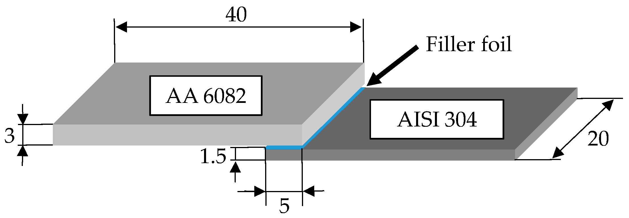
2. Materials and Experimental Procedure

2.1. Materials

AA 6082 sheets and AISI 304 sheets with dimensions according to Figure 1 were used as base materials. The Al-Ge-Si brazing alloy was applied as a melt-spun foil and produced using the ultrafast solidification of a flat melt jet on a rotating copper disk. The element contents of the used alloys are presented in Table 1.
The joints were manufactured with an overlap length of 5 mm. The aluminum alloy sheet was twice as thick as the stainless-steel sheet. As a result, the deformation and the bending of the aluminum base material were reduced during the tensile shear and fatigue tests, and thus, determining the mechanical properties of the brazed joint was possible without the significant influence of the aluminum base material.

2.2. Experimental Procedure
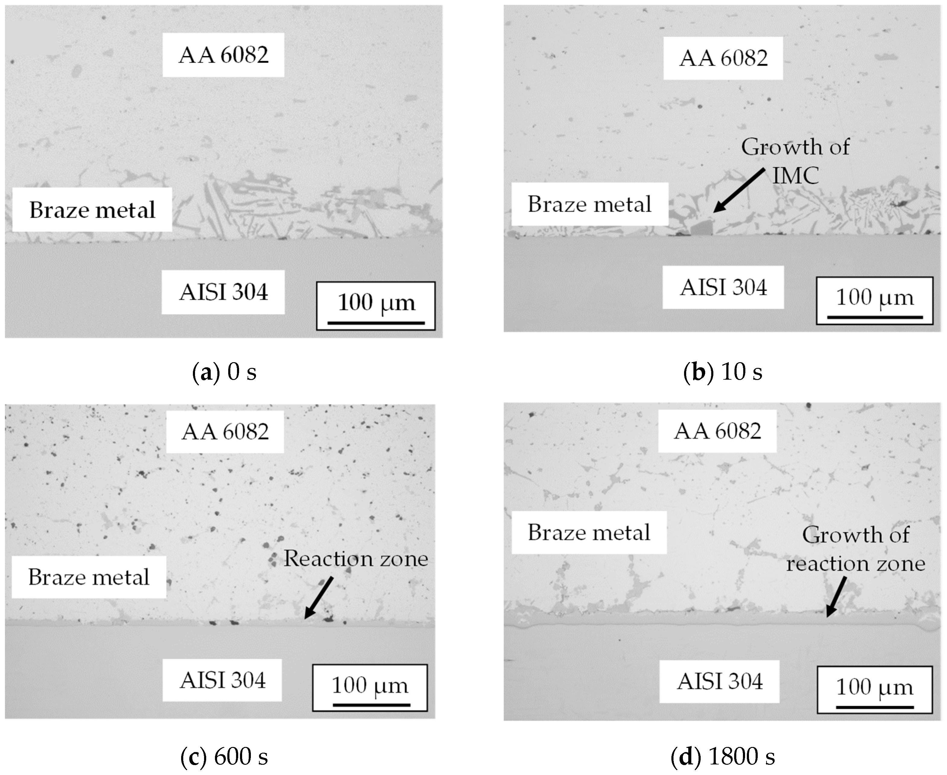
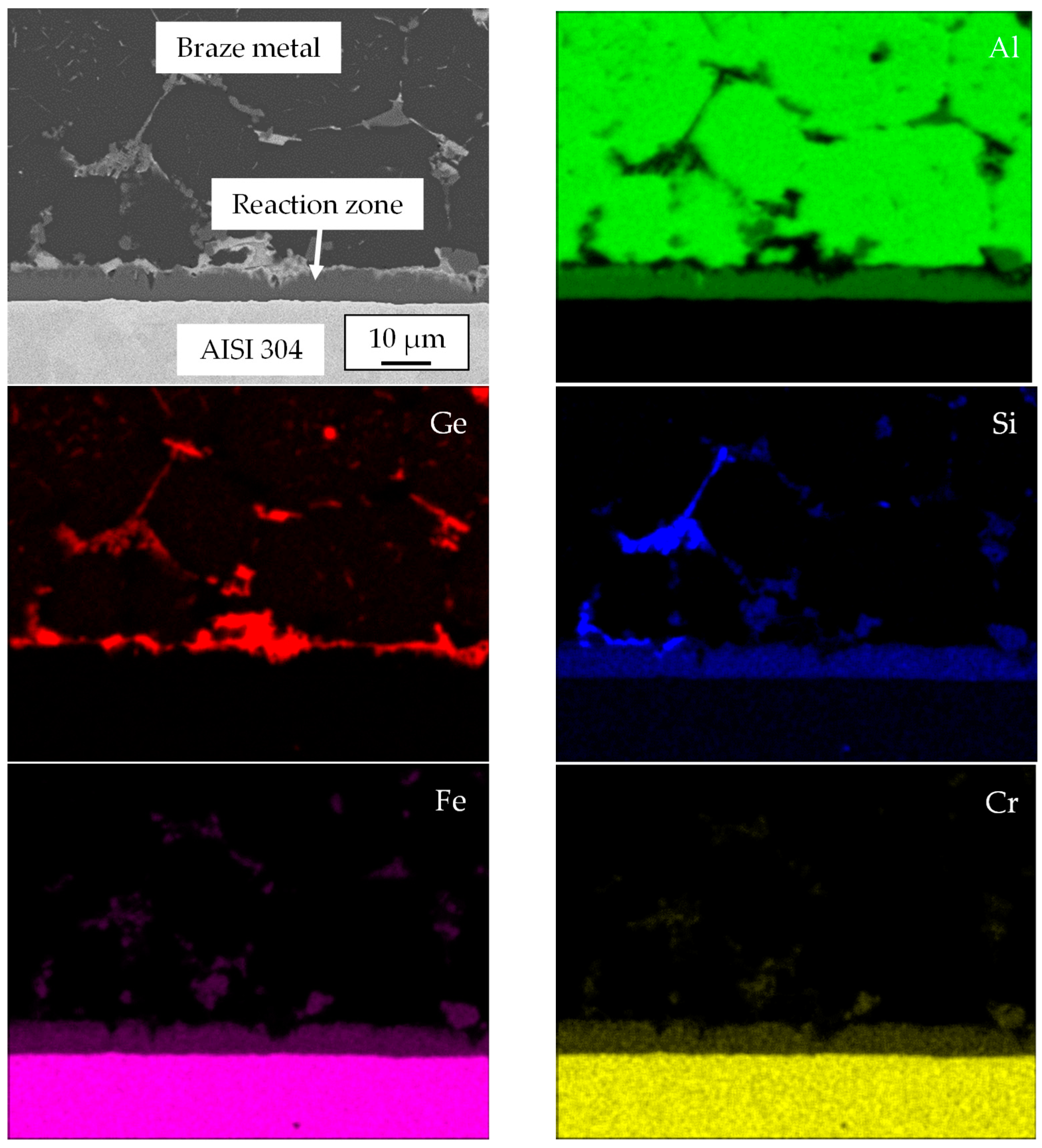
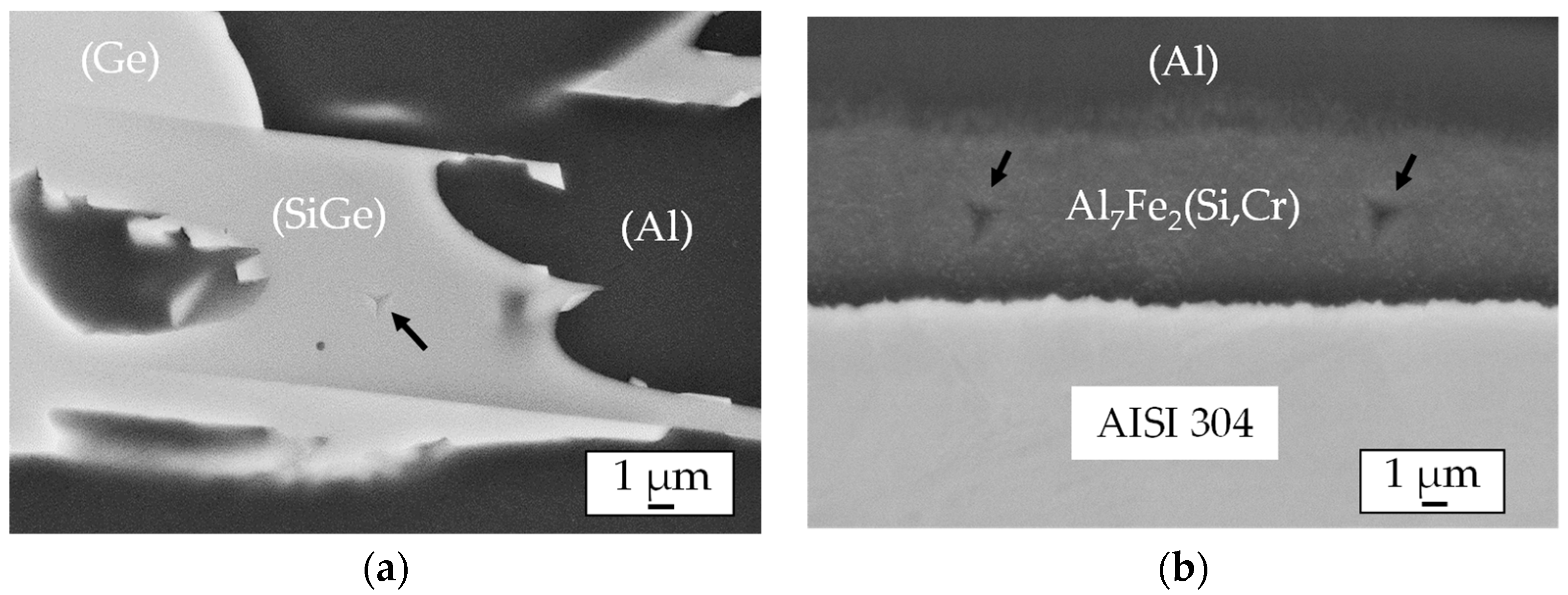
AA 6082/AISI 304 joints were produced via induction brazing and vacuum furnace brazing using the process parameters shown in Table 2. The samples were brazed at a temperature of 530 °C. Induction brazing was carried out using a CsAlF Complex flux (Solvay GmbH, Hannover, Germany) in an argon atmosphere. The total time of the process, including cooling time, was about 2 min. The filler foil and the base materials were fluxed before brazing. The samples were cooled freely afterward. For the induction brazing, the temperature was measured by a pyrometer Impac® (IMPAC Electronic GmbH, Frankfurt, Germany). For vacuum furnace brazing, the temperature was measured in the base material under the brazed surface using a thermocouple K type. A heating rate of 10 K/min was used.
The microstructural constituents of the braze metal and the reaction zone show a small size. Thus, their indentation hardness and elastic indentation modulus could only be determined by nanoindentation using low indentation loads. Nanoindentation measurements were carried out using a nanoindenter UNAT with a Berkovich indenter (Asmec GmbH, Dresden, Germany). ISO 14577-1 and Bull describe the measurement principle in detail [26,27]. To compare the results with previous works [23,25], the same measurement parameters and boundary conditions were used in the present work. The indentations consist of three steps: loading (10 s), holding at a maximum force of 20 mN (5 s) and unloading (4 s). The indenter was calibrated for the maximum force using sapphire and quartz. The evaluation of the results was carried out with Poisson’s ratio of ν = 0.34 [28,29].
The joining strength and fatigue behavior were investigated by tensile shear tests as well as fatigue tests at an ambient temperature. The monotonic tests were performed on a material testing machine, Zwick Allround-Line 20 kN (ZwickRoell GmbH & Co. KG, Ulm, Germany). They were carried out with a speed of 0.01 mm/s. For statistical validation, five samples per brazing parameter were tested.
The fatigue tests were carried out to evaluate the lifetime of the brazed joints under cyclic loading. The tests were conducted on a resonance pulsator RUMUL (Russenberger Prüfmaschinen AG, Neuhausen am Rheinfall, Switzerland) under a load-controlled condition using a load ratio of 0.1 at an ambient temperature. A resonance frequency of 100 Hz arose. To determine the fatigue strength of the brazed joints, four stress amplitudes were used. Three samples per stress amplitude were tested until a number of 107 cycles was reached.
The microstructure of the brazed joints and the formation of the cracks caused by mechanical testing were characterized with the help of cross-sections. The microstructure was investigated by a scanning electron microscope (SEM) Zeiss Leo 1455VP (Carl Zeiss Microscopy GmbH, Jena, Germany) using a backscattered electron detector (BSD). The element content of the detected microstructural constituents was analyzed by energy-dispersive X-ray spectroscopy Ametek Genesis MK2 (AMETEK GmbH, Meerbusch, Germany) in SEM.

3. Results

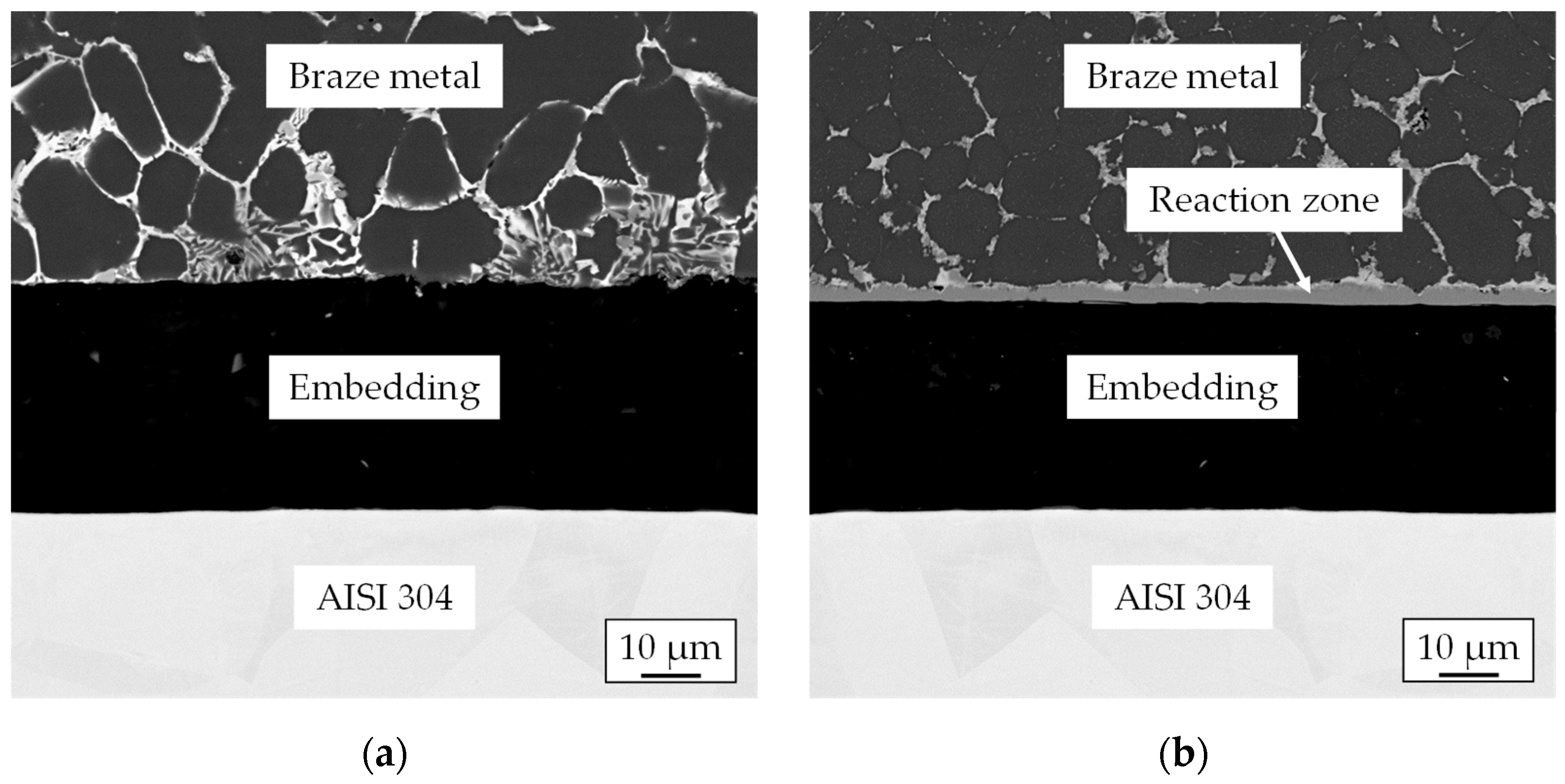
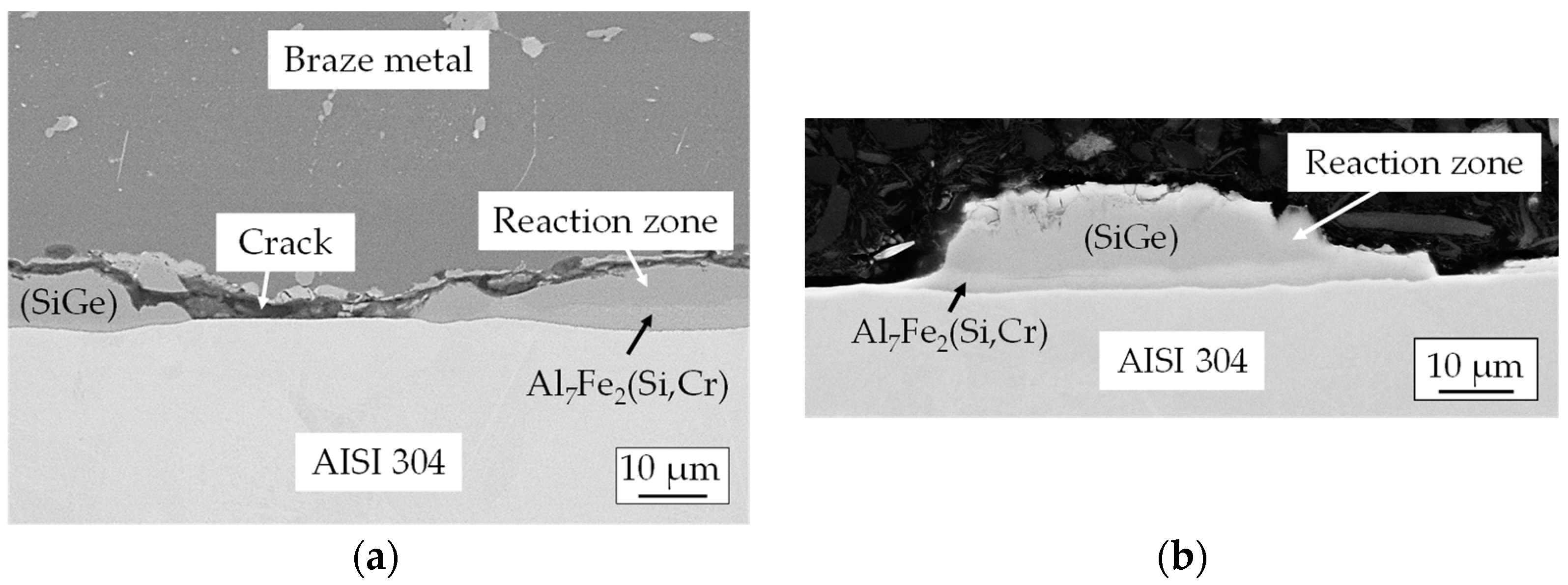
3.1. Microstructure of the AA 6082/AISI 304 Brazed Joints

The microstructures of AA 6082/AISI 304 brazed joints are presented in Figure 2. On the AA 6082 side, joints were formed due to the interaction of the liquid filler metal with the aluminum base material. According to Wittke [30], it can be named as a type of welded joint with regard to its microstructure. As a result, a gap width of about 100 µm arose. This corresponded to the required brazing gap range of 0.1 to 0.25 mm for aluminum alloy joints produced via induction brazing [31]. Due to the mutual diffusion of atoms of the braze metal and stainless steel, a reaction zone close to stainless steel was formed. In induction-brazed joints, a reaction zone with a thickness of 2 µm was formed on the AISI 304 side. With the increasing holding time, the growth of the IMC at the interface to the stainless steel could be seen. In the vacuum-brazed joints, the reaction zone was significantly thicker (10 μm). It continued to grow with increasing holding time.
Due to the small thickness of the reaction zone in the induction-brazed joints, it was difficult to carry out an exact investigation of the microstructure of the braze metal and the reaction zone, as well as to determine its chemical composition. Therefore, SEM investigations were performed on a vacuum-brazed joint produced at 530 °C for 600 s. The microstructure and qualitative elemental distribution are shown in Figure 3. The braze metal consisted of an Al solid solution with Ge plus Si precipitates at the grain boundaries. In addition, Fe and Cr particles of the stainless steel could be found in the brazing metal. Moreover, large amounts of Fe and Cr were detected in the reaction zone. Two intermetallic layers were distinguished. The reaction zone was about 10 µm thick.
In order to determine the chemical compositions of the microstructural constituents in the braze metal and the reaction zone, local EDXS analyses were carried out, as shown in Figure 4. The positions of the measuring points of the EDXS analyses and the detected phases are listed in Table 3. Al, Ge and SiGe solid solutions, as well as Al7Fe2Si precipitates, were identified in the braze metal. In addition, two intermetallic layers consisting of the SiGe solid solution and Al7Fe2(Si,Cr) compound were identified in the reaction zone. The same Al7Fe2(Si,Cr) layer was also detected in the reaction zone of the joints brazed with Al-40.0Ge-3.4Si by Ivannikov et al. [24].

3.2. Nanoindentation Results

Nanoindentation measurements were performed on a vacuum-brazed joint produced at 530 °C for 600 s. Thereby, the mechanical properties of microstructural constituents were measured. In order to compare the influence of their mechanical properties on the indent size, indents in the SiGe solid solution and in the Al7Fe2(Si,Cr) intermetallic layer at the interface to stainless steel are presented in Figure 5. All indents showed good positioning and an acceptable distance to adjacent microstructural constituents. Compared to the indent set in the SiGe solid solution (Figure 5a), the indents produced in the Al7Fe2(Si,Cr) intermetallic layer (Figure 5b) showed a slightly higher penetration depth and a bigger contact area. Hence, the Al7Fe2(Si,Cr) intermetallic layer has a lower indentation hardness than the SiGe solid solution.
The nanoindentation results are summarized in Figure 6. Clearly, the SiGe solid solution and the Al7Fe2Si precipitates had a higher hardness than that of other microstructural constituents (light gray bars in Figure 6). The indentation hardness of the SiGe solid solution was 11.5 GPa, and for Al7Fe2Si precipitates, 11.8 GPa was determined. The Al7Fe2(Si,Cr) intermetallic layer (10.5 GPa) and the Ge solid solution (10.2 GPa) were slightly softer. The Al solid solution showed a hardness of 0.7 GPa. The high hardness of the SiGe solid solution and Al7Fe2(Si,Cr) intermetallic layer could cause crack formations in the reaction zone during mechanical testing. In addition, the indentation modulus of the Al solid solution was lower than those of other constituents (dark gray bars in Figure 6). This indentation modulus was 71.1 GPa, while Ge and SiGe solid solutions, the Al7Fe2(Si,Cr) intermetallic layer and Al7Fe2Si precipitates had an elastic indentation moduli of 125.4 GPa and 144.1 GPa, 160.7 GPa and 191.6 GPa, respectively. Ivannikov et al. and Fedorov et al. determined the similar hardness and elastic moduli of the microstructural constituents in both the Al-40.0Ge-3.4Si filler metal and AA 2017/AISI 304 joints brazed using Al-Ag-Cu-Si filler metal [23,25].

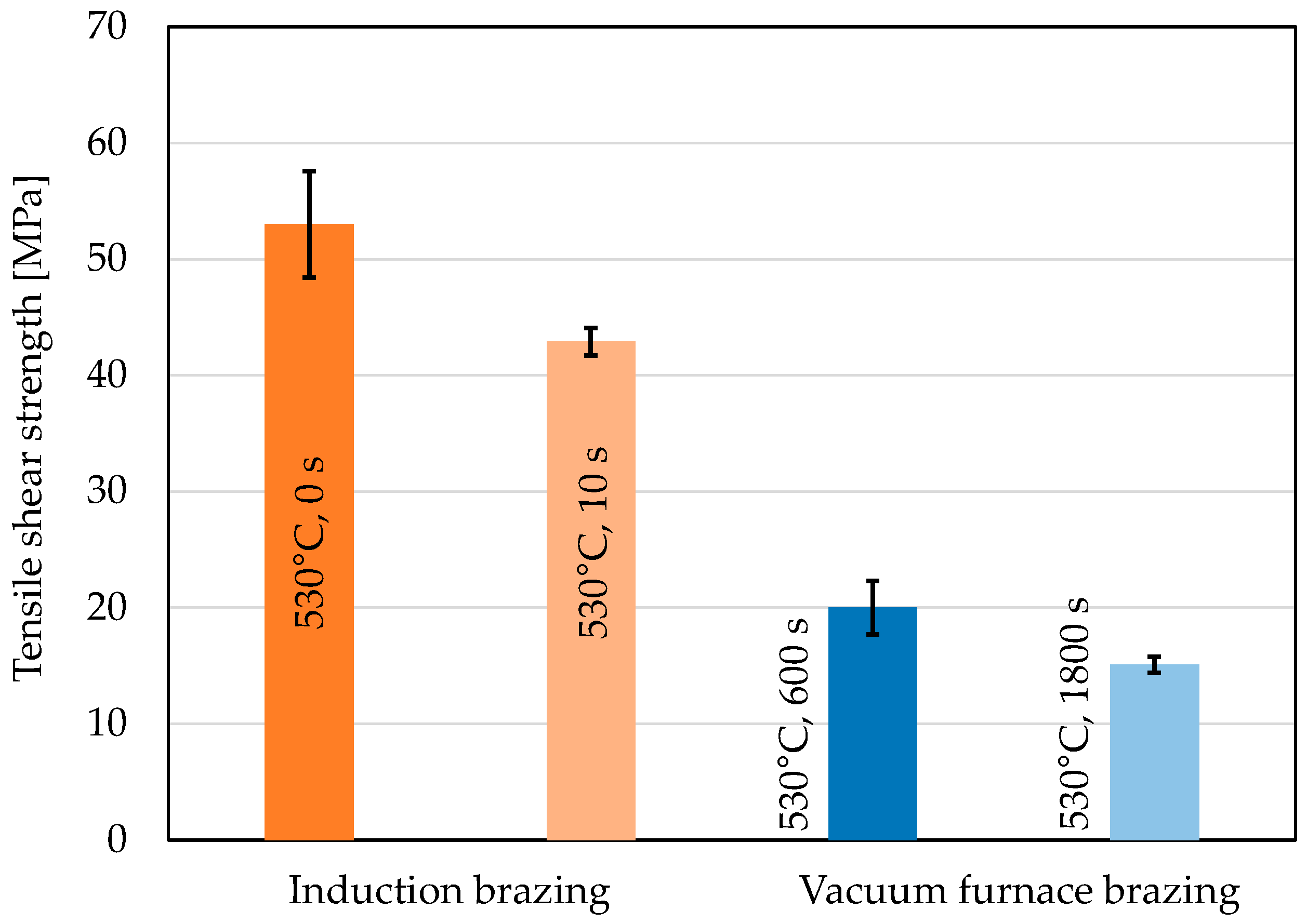
3.3. Tensile Shear Strength of the AA 6082/AISI 304 Brazed Joints

The tensile shear strengths of the brazed joints are shown in Figure 7. The induction-brazed joints had a higher strength than vacuum-brazed joints. Joints brazed at 530 °C without a holding time reached the highest joining strength, which averaged 53 MPa. This strength is clearly higher than the determined values of joints brazed with the Al-Ag-Cu-Si brazing alloy (32 MPa). The authors reported that joints failed in the reaction zone and explained this due to their high hardness and thickness [25]. Vacuum-brazed joints produced at 530 °C for 600 s reached a maximum joining strength of 20 MPa. This strength was higher than that determined by Ivannikov et al. (15 MPa). For all investigated joints, the strength decreased with increasing holding time. This could be explained by the high thickness of the reaction zone. In addition, the holding time of 30 min used by Ivannikov et al. led to the migration of Ge into the aluminum base material and the strong diffusion of Si from the braze metal into the reaction zone. As a result, the Al7Fe2(Si,Cr) intermetallic layer in the reaction zone grew further [24].
Cross sections of the fracture surfaces were investigated using SEM, as shown in Figure 8. It was found that the same fracture mechanism took place in all brazed joints during monotonic tensile shear tests. The samples failed in the reaction zone, especially inside the Al7Fe2(Si,Cr) intermetallic layer. Clearly, the thickness of the reaction zone increased with increasing holding time. This caused a reduction in the tensile shear strength values and affected the fracture mechanism. Due to the thin reaction zone in the induction-brazed joints, no residue in this zone on the braze metal, as well as on the surface of stainless steel, was identified, as shown in Figure 8a. By contrast, the residue of the reaction zone that adhered to the braze metal could be seen in the tested samples produced using vacuum furnace brazing, as seen in Figure 8b. Residues on the steel side could not be detected.

3.4. Fatigue Behavior of the AA 6082/AISI 304 Brazed Joints

The fatigue behavior was determined using joints brazed at 530 °C for 0 s and at 530 °C for 600 s. The fatigue strength values of the brazed joints are shown in Figure 9. Induction-brazed joints reached a number of 3 × 10³ cycles at the highest stress level of 22 MPa, which is similar to the maximum monotonic tensile shear strength of vacuum-brazed joints. At a stress amplitude of 7 MPa, a number 1 × 10⁷ cycles was reached. For the vacuum-brazed joints, fatigue tests started at a stress level of 8 MPa, which was close to the lowest stress level of the tests for the induction-brazed joints. At this stress level, the vacuum-brazed joints achieve a number of 2 × 10³. 1 × 10⁷ cycles were reached at a stress amplitude of 3 MPa. The low fatigue strength of vacuum-brazed joints could be explained by the long holding time, which resulted in the growth of the reaction zone.
After the fatigue tests, the fracture surfaces of the tested samples were investigated by SEM. The cross-sections of the induction-brazed samples are shown in Figure 10. The fracture surface of the “run out” sample, which reached a number of 1 × 10⁷ cycles at a stress amplitude of 7 MPa, is presented in Figure 10a. The crack occurred inside the reaction zone and ran into the braze metal at the grain boundaries. This could be explained by the high hardness of the Al7Fe2(Si,Cr) intermetallic layer formed in the reaction zone and the SiGe solid solution formed in the braze metal. At a stress amplitude of 22 MPa, the samples failed in the braze metal close to the reaction zone. This was detected using the EDXS analyses of a residue of the braze metal adhering to stainless steel, Figure 10b. Hence, the reaction zone influenced crack formation.
Analogously, the vacuum-brazed samples were investigated by SEM. The fracture surface of the “run out” sample, which achieved a number of 1 × 10⁷ cycles, and the fracture surface of the sample, which failed at a number of 2 × 10³ cycles at a stress amplitude of 8 MPa, are shown in Figure 11. In the fracture surface of the “run out” sample, the crack arose inside the reaction zone and ran through the SiGe solid solution, as shown in Figure 11a. For the sample, which failed at a stress amplitude of 8 MPa, the fracture also occurred in the reaction zone. This was detected using the EDXS analyses of a residue with the SiGe solid solution and the Al7Fe2(Si,Cr) intermetallic layer adhering to the stainless steel, Figure 11b. Consequently, the reaction zone affected the fracture mechanism of these brazed joints predominantly.

4. Conclusions

By using low-melting filler metals, the erosion of the aluminum base material, which can occur during the brazing process, could be avoided. AA 6082/AISI 304 joints were successfully manufactured by induction brazing and vacuum furnace brazing using an Al-40.0Ge-3.4Si filler metal. In induction-brazed joints, the reaction zone was about 2 µm thick, while vacuum-brazed joints showed a reaction zone of about 10 μm. Two intermetallic layers consisting of the SiGe solid solution and Al7Fe2(Si,Cr) compound were identified in the reaction zone. Joints brazed at 530 °C without a holding time achieved a maximum joining strength of 53 MPa. Vacuum-brazed joints produced at 530 °C for 600 s reached a maximum joining strength of 20 MPa. The increasing holding time resulted in a decrease in the joining strength due to the strong diffusion of Si from the braze metal into the reaction zone and, thus, the growth of the hard intermetallic layer Al7Fe2(Si,Cr) in the reaction zone. Fractographic investigations show that all brazed joints had the same fracture mechanism. The fracture arose in the reaction zone, especially inside the Al7Fe2(Si,Cr) intermetallic layer. During fatigue tests, induction-brazed joints reached a number of 1 × 10⁷ cycles at a stress amplitude of 7 MPa, while vacuum-brazed joints achieved this at a stress amplitude of 3 MPa. In comparison to the induction-brazed joints, the low fatigue strength of vacuum-brazed joints could be explained by the long holding time and, thus, the high thickness of the reaction zone. In addition, the reaction zone influenced the crack formation. In the induction of brazed joints, a crack arose inside the reaction zone and ran into the braze metal at the Al grain boundaries, while a crack was formed inside the reaction zone and ran through the SiGe solid solution in vacuum-brazed joints. The influence of the reaction zone on the fracture mechanism could be explained by internal stress in the reaction zone caused by the high hardness and the increase in thickness of the microstructural constituents: the SiGe solid solution and the Al7Fe2(Si,Cr) intermetallic layer. In comparison to the hardness of the Al solid solution of 0.7 GPa, the SiGe solid solution and the Al7Fe2(Si,Cr) intermetallic layer showed significantly higher hardness values of 11.5 GPa and 10.5 GPa, respectively.
With regard to the geometry of the brazed components, it is recommended to produce AA 6082/AISI 304 joints either by induction brazing at 530 °C without a holding time or in a vacuum furnace at 530 °C for 600 s.

Author Contributions

Conceptualization, V.F.; methodology, V.F., T.U. and G.W.; formal analysis, V.F.; investigation, V.F.; resources, G.W.; writing—original draft preparation, V.F.; writing—review and editing, V.F., T.U. and G.W.; visualization, V.F.; supervision, T.U. and G.W.; funding acquisition, V.F. and G.W. All authors have read and agreed to the published version of the manuscript.

Funding

This research was funded by the Deutsche Forschungsgemeinschaft (DFG, German Research Foundation), project number WA 1665/16-1. The publication of this article was funded by the Deutsche Forschungsgemeinschaft (DFG, German Research Foundation), project number 491193532 and by the Chemnitz University of Technology.

Data Availability Statement

Not applicable.

Conflicts of Interest

The authors declare no conflict of interest.

References

  1. Ahn, B. Recent advances in brazing fillers for joining of dissimilar materials. Metals 2021, 11, 1037. [Google Scholar] [CrossRef]
  2. Wallerstein, D.; Salminen, A.; Lusquiños, F.; Comesaña, R.; García, J.D.V.; Rodríguez, A.R.; Pou, J. Recent developments in laser welding of aluminum alloys to steel. Metals 2021, 11, 622. [Google Scholar] [CrossRef]
  3. Fedorov, V.; Uhlig, T.; Wagner, G. Investigation of fatigue damage in aluminum/stainless steel brazed joints. Weld. World 2018, 62, 609–616. [Google Scholar] [CrossRef]
  4. Yang, J.; Oliveira, J.P.; Li, Y.; Tan, C.; Gao, C.; Zhao, Y.; Yu, Z. Laser techniques for dissimilar joining of aluminum alloys to steels: A critical review. J. Mater. Process. Technol. 2022, 301, 117443. [Google Scholar] [CrossRef]
  5. Li, R.; Yuan, X.; Zhang, H.; Yang, J.; Wu, K.; Li, T.; Tao, S. Effect of axial magnetic field on TIG welding–brazing of AA6061 aluminum alloy to HSLA350 steel. J. Mater. Res. Technol. 2021, 12, 882–893. [Google Scholar] [CrossRef]
  6. Kayamoto, T.; Saito, S.; Ogusu, M.; Onzawa, T. Vacuum brazing of 2017 aluminum alloy using Al-Ge-Cu based fillers. Q. J. Jpn. Weld. Soc. 1996, 14, 63–68. [Google Scholar] [CrossRef]
  7. Ostermann, F. Anwendungstechnologie Aluminium; Springer: Berlin/Heidelberg, Germany, 2007. [Google Scholar]
  8. Bach, F.-W.; Möhwald, K.; Holländer, U.; Tiemann, S. Flussmittelfreies Hartlöten unter reaktiver Prozessgasatmosphäre—Ein alternatives Verfahren zum Fügen von Aluminiumwerkstoffen. Mater. Werkst. 2008, 39, 594–598. [Google Scholar] [CrossRef]
  9. Dai, W.; Xue, S.B.; Ji, F.; Lou, J.; Sun, B.; Wang, S.Q. Brazing 6061 aluminum alloy with Al-Si-Zn filler metals containing Sr. Int. J. Miner. Metall. Mater. 2013, 20, 365–370. [Google Scholar] [CrossRef]
  10. Yu, G.; Sun, H.; Teng, F.; Chen, S.; Huang, J.; Yang, J.; Zhao, Z. Influence of Si Addition on Microstructure, Mechanical Properties, and Corrosion Resistance of Al/Steel Brazing Joint Using Zn-15Al-XSi Filler Metals. J. Mater. Eng. Perform. 2023, 1–11. [Google Scholar] [CrossRef]
  11. Chuang, T.H.; Tsao, L.C.; Tsai, T.C.; Yeh, M.S.; Wu, C.S. Development of a low-melting-point filler metal for brazing aluminum alloys. Metall. Mater. Trans. A 2000, 31, 2239–2245. [Google Scholar] [CrossRef]
  12. Chang, S.Y.; Tsao, L.C.; Li, T.Y.; Chuang, T.H. Joining 6061 aluminum alloy with Al–Si–Cu filler metals. J. Alloys Compd. 2009, 488, 174–180. [Google Scholar] [CrossRef]
  13. Pei, C.; Wu, X.; Zhang, G.; Cheng, Y.; Ren, X.; Wang, W.; Xiong, H. Microstructures and mechanical properties of brazed 6063 aluminum alloy joint with Al-Cu-Si-Ni filler metal. Weld. World 2020, 64, 1933–1938. [Google Scholar] [CrossRef]
  14. Peng, C.; Zhu, D.; Li, K.; Du, X.; Zhao, F.; Wan, M.; Tan, Y. Research on a low melting point Al-Si-Cu (Ni) filler metal for 6063 aluminum alloy brazing. Appl. Sci. 2021, 11, 4296. [Google Scholar] [CrossRef]
  15. Hayes, F.H.; Longbottom, R.D.; Ahmad, E.; Chen, G. On the Al-Si, Al-Ge, and Al-Ge-Si systems and their application to brazing in high power semiconductor devices. J. Phase Equilibria 1993, 14, 425–431. [Google Scholar] [CrossRef]
  16. Xu, R.; Zhao, H.; Li, J.; Liu, R.; Wang, W.K. Microstructures of the eutectic and hypereutectic Al-Ge alloys solidified under different pressures. Mater. Lett. 2006, 60, 783–785. [Google Scholar] [CrossRef]
  17. Kötzing, B. Entwicklung Niedrigschmelzender Aluminiumbasislote zum Fügen Höherlegierter Aluminiumwerkstoffe. Ph.D. Thesis, RWTH Aachen University, Aachen, Germany, 1997. [Google Scholar]
  18. Kim, H.J.; Lee, G.H.; Jung, J.P. A Review of the Brazeability of Low-Temperature and Nano-Reinforced Al-Based Brazing Filler Metals. J. Weld. Join. 2022, 40, 216–224. [Google Scholar]
  19. Niu, Z.W.; Huang, J.H.; Chen, S.H.; Zhao, X.K. Effects of germanium additions on microstructures and properties of Al–Si filler metals for brazing aluminum. Trans. Nonferrous Met. Soc. 2016, 26, 775–782. [Google Scholar] [CrossRef]
  20. Niu, Z.; Huang, J.; Liu, K.; Xu, F.; Chen, S.; Zhao, X. Brazing of 6061 aluminum alloy with the novel Al-Si-Ge-Zn filler metal. Mater. Lett. 2016, 179, 47–51. [Google Scholar] [CrossRef]
  21. Sabadash, O.M.; Maksymova, S.V. Fluxless brazing of aluminium alloys by brazing filler metal of Al-Ge system. Autom. Weld. 2023, 4, 50–56. [Google Scholar] [CrossRef]
  22. Schubert, T.H.; Loser, W.; Teresiak, A.; Mattern, N.; Bauer, H.D. Preparation and phase transformations of melt-spun Al-Ge-Si brazing foils. J. Mater. Sci. 1997, 32, 2181–2189. [Google Scholar] [CrossRef]
  23. Ivannikov, A.; Fedorov, V.; Abramov, A.; Penyaz, M.; Bachurina, D.; Uhlig, T.; Suchkov, A.; Wagner, G.; Morokhov, P.; Sevryukov, O. Development of Rapidly-Quenched Al-Ge-Si Filler Alloys for the Joining of Stainless Steel AISI 304 and Aluminum Alloy AA6082. Metals 2021, 11, 1926. [Google Scholar] [CrossRef]
  24. Ivannikov, A.; Abramov, A.; Popov, N.; Penyaz, M.; Suchkov, A.; Pukhareva, N.; Sevryukov, O. Joining Stainless-Steel AISI 304 and High-Strength Aluminum Alloy AA 6082 by Brazing Using Al-Ge-Si Foils. Metals 2023, 13, 149. [Google Scholar] [CrossRef]
  25. Fedorov, V.; Uhlig, T.; Wagner, G. Structure-Property Relationship in High-Strength Aluminum Alloys/Stainless Steel Brazed Joints. Metals 2023, 13, 242. [Google Scholar] [CrossRef]
  26. ISO 14577-1:2015; Metallic Materials—Instrumented Indentation Test for Hardness and Materials Parameters—Part 1: Test method. International Organization for Standardization: Geneva, Switzerland, 2015. Available online: https://www.iso.org/standard/56626.html (accessed on 1 July 2015).
  27. Bull, S.J. Extracting hardness and Young’s modulus from load–displacement curves. Int. J. Mater. Res. 2022, 93, 870–874. [Google Scholar] [CrossRef]
  28. Sudharshan Phani, P.; Oliver, W.C.; Pharr, G.M. Measurement of hardness and elastic modulus by load and depth sensing indentation: Improvements to the technique based on continuous stiffness measurement. J. Mater. Res. 2021, 36, 2137–2153. [Google Scholar] [CrossRef]
  29. Oliver, W.C.; Pharr, G.M. An improved technique for determining hardness and elastic modulus using load and displacement sensing indentation experiments. J. Mater. Res. 1992, 7, 1564–1583. [Google Scholar] [CrossRef]
  30. Wittke, K. Löten. In Wissenschaftliche Schriftenreihe der Technischen Hochschule Karl-Marx-Stadt; Technische Hochschule: Karl-Marx-Stadt, Germany, 1980; Volume 10, pp. 1–94. [Google Scholar]
  31. Müller, W. Löttechnik: Leitfaden für die Praxis; DVS-Verlag: Düsseldorf, Germany, 1995. [Google Scholar]
Figure 1. Scheme of the single lap shear sample. Values are given in mm.
Metals 13 01574 g001
Figure 2. Microstructure of the joints: induction-brazed (a,b), vacuum furnace-brazed (c,d).
Metals 13 01574 g002
Figure 3. BSD image of the microstructure and qualitative EDXS elemental distribution of Al, Ge, Si, Fe and Cr at the interface to stainless steel in a vacuum-brazed joint produced at 530 °C for 600 s.
Metals 13 01574 g003
Figure 4. BSD image of the reaction zone in a vacuum-brazed joint produced at 530 °C for 600 s with EDXS measurement points.
Metals 13 01574 g004
Figure 5. BSD images of indents set in: (a) SiGe solid solution; (b) Iintermetallic layer Al7Fe2(Si,Cr).
Metals 13 01574 g005
Figure 6. Nanoindentation results.
Metals 13 01574 g006
Figure 7. Joining strengths of the brazed joints.
Metals 13 01574 g007
Figure 8. BSD images of the fracture surfaces of monotonic-tested samples produced using: induction brazing, 530 °C for 0 s (a), vacuum furnace brazing, 530 °C for 600 s (b).
Metals 13 01574 g008
Figure 9. Fatigue strength values of the joints produced using induction brazing at 530 °C for 0 s and using vacuum furnace brazing at 530 °C for 600 s.
Metals 13 01574 g009
Figure 10. BSD images of the fracture surfaces of fatigue-tested samples: (a) “run out” sample (stress amplitude: 7 MPa, number of cycles: 1 × 10⁷), (b) broken sample (stress amplitude: 22 MPa, number of cycles: 3 × 10³); brazing process: induction brazing.
Metals 13 01574 g010
Figure 11. BSD images of the fracture surfaces of fatigue-tested samples: (a) “run out” sample (stress amplitude: 3 MPa, number of cycles: 1 × 10⁷), (b) broken sample (stress amplitude: 8 MPa, number of cycles: 2 × 10³); brazing process: vacuum furnace brazing.
Metals 13 01574 g011
Table 1. Chemical compositions of the brazing alloy and base materials [24].
Alloy Element Content (wt.%)
AlFeGeCrNiSiMnMgCOther
AA 6082bal.0.5-0.25-0.811-0.4
AISI 304-bal.-1880.41.4-0.080.3
Al-Ge-Sibal.-40--3.4----
Table 2. Process parameters.
Brazing ProcessBrazing Temperature [°C]Holding Time [s]
Induction brazing530010
Vacuum furnace brazing5306001800
Table 3. Results of the EDXS analyses performed on the cross section (Figure 4).
Measurement PointsElement Content (at.%)Microstructural Constituents
AlGeSiFeCr
Braze Metal
1973---(Al)
2-4555--(SiGe)
370-11181Al7Fe2Si
4595---(Ge)
Reaction Zone
5-4159--(SiGe)
665-9185Al7Fe2(Si,Cr)
Disclaimer/Publisher’s Note: The statements, opinions and data contained in all publications are solely those of the individual author(s) and contributor(s) and not of MDPI and/or the editor(s). MDPI and/or the editor(s) disclaim responsibility for any injury to people or property resulting from any ideas, methods, instructions or products referred to in the content.

