Article

Phase Composition and Microstructure of Cast Al-6%Mg-2%Ca-2%Zn Alloy with Fe and Si Additions

1
Sector of Project Activities, Moscow Polytechnical University, Bolyshaya Semenovskaya Str. 38, 107023 Moscow, Russia
2
Brunel Centre for Advanced Solidification Technology (BCAST), Brunel University London, Middlesex, Uxbridge UB8 3PH, UK
3
Institute of New Materials and Nanotechnology, National University of Science and Technology MISIS, Leninsky Prospekt 4, 119049 Moscow, Russia
4
Department of Physical Materials Science, National University of Science and Technology MISIS, Leninsky Prospekt 4, 119049 Moscow, Russia
5
Ishlinsky Institute for Problems in Mechanics RAS, Russian Academy of Sciences, 119526 Moscow, Russia
*
Author to whom correspondence should be addressed.
Metals 2023, 13(9), 1584; https://doi.org/10.3390/met13091584
Submission received: 30 June 2023 / Revised: 5 August 2023 / Accepted: 5 September 2023 / Published: 12 September 2023

Abstract

:
Investigating the effect of Fe and Si is essential for any new Al-based composition, as these impurities can be easily found both after primary production and recycling. This study is dedicated to filling the gap in revealing the phase composition of an Al-6%Mg-2%Ca-2%Zn alloy after the combined and separate addition of Fe and Si. This was addressed by permanent mold casting and solid solution heat treatment. The investigation of slowly solidified samples also contributed to understanding potential phase transitions. It was found that the alloy containing 0.5%Fe can have nearly spherical intermetallics after heat treatment, whereas a higher Fe content brought the formation of a needle-shaped Al3Fe intermetallic. We explain this by the formation of a ternary α-Al + Al10CaFe2 + Al4Ca eutectic, which is more compact in as-cast condition compared to divorced binary α-Al + Al4Ca and α-Al + Al3Fe eutectics. Similarly, 0.5%Si readily incurred the formation of a needle-shaped Al2CaSi2 intermetallic, probably also by a binary reaction L → α-Al + Al2CaSi2. In the solidified samples, no Mg2Si phase was found, even in slowly solidified samples. This is contrary to the thermodynamic calculation, which suggests a peritectic reaction L + Al2CaSi2 Mg2Si. Interestingly, the addition of 0.5%Si caused an even coarser microstructure compared to the addition of 1%Fe, which caused the appearance of a primary Al3Fe phase. We conclude that the new alloy is more tolerable to Fe rather than Si. Specifically, the addition of 0.5%Fe can be added while maintaining a fine morphology of the eutectic network. It was suggested that the morphology of eutectic and solid solution hardening governed the mechanical properties. The strength of the alloys containing separate 0.5%Fe (UTS = 215 ± 8 MPa and YS 146 ± 4 = MPa) and the combined 0.5%Fe and 0.5%Si additions (UTS = 195 ± 14 MPa and YS ± 1 = 139 MPa) was not compromised compared to the alloy containing 0.5%Si (UTS 201 ± 24 = MPa and YS = 131 ± 1 MPa).

1. Introduction

Eutectic alloys based on Al-Ni [1,2,3,4,5,6,7,8,9], Al-Ce(La) [9,10,11,12,13,14,15,16,17,18], and Al-Ca [17,18,19,20,21,22,23,24] systems have been considered an alternative to Al-Si alloys because they can also ensure high fluidity and resistance to hot cracking during solidification. In addition to eutectic-forming elements, high-soluble elements such as Mg, Cu, and Zn are used to increase the strength by the formation of shearable precipitates after quenching and aging treatment. It is recognized that Mg and Zn in Al alloys bring the highest strengthening potential because of their high solubility in solid (Al) matrix at high temperatures. This solubility sharply decreases with cooling, resulting in the precipitation of metastable precursors of MgZn2 and/or Al2Mg3Zn3 phases. For example, this effect was successful in AA7xxx alloys based on the Al-Zn-Mg system [25,26,27,28,29].
Many studies have reported that the alloys based on the Al-Ni and Al-Ceeutectic systems perform very well in additive manufacturing. The thermal stability of rapidly solidified microstructure is improved compared to Al-Si alloys because of the negligible solubility of Ni and rare-earth elements [30,31,32,33,34]. However, these alloys have been rarely reported with conventional casting. Despite the similarities in the eutectic microstructure with Al-Si alloys, Al-Ni and Al-Ce(La) alloys can hardly be considered a sustainable alternative because of the high cost of Ni and rare-earth elements. Ca, however, is abundant in the earth’s crust and has other advantages, such as a low density (1.55 g/cm3) and the ability to form dense Ca-oxides on the melt surface. In recent research [35], it was shown that such oxides seal the melt from the surrounding environment, preventing Mg evaporation. This might be a beneficial feature of lightweight Al-Mg-Ca casting alloys in addition to a better hot tearing resistance compared to a Ca-free counterpart, which we reported in [23]. This effect accounts for a very high volume fraction of eutectic Al4Ca intermetallics. At the same concentration of eutectic element, the amount of binary intermetallic in Al-Ca eutectic alloy is more than three times higher than in Al-Ni and Al-Ce(La) alloys or eutectic (Si) particles in Al-Si alloys [36]. This may potentially allow for an extended window for Ca concentration to control the properties of the alloy.
The Al-Mg alloy family represents an important class of alloys for applications that require high formability and corrosion resistance. In Al-Ca-Mg alloys, there were no Al-Ca-Mg compounds reported. Their microstructure consisted of an equilibrium Al4Ca phase and a non-equilibrium Al3Mg2 phase formed at about 580 °C and 445 °C, respectively [37]. The temperature of non-equilibrium solidus does not change significantly after the addition of Zn [38,39]. The increase in casting properties due to the addition of Ca was attributed to a lower liquidus temperature and a greater fraction of eutectic Ca-rich liquid capable of healing cracks [40]. Thus, Al-Mg-Ca-Zn alloys may be a good choice for lightweight heat-treatable casting alloys that could have optimized density. The density can be tuned by regulating the Mg/Zn ratio. Specifically, we suggest a Mg/Zn ratio < 3 and a composition of Al-6%Mg-2%Zn-2% Ca, which can still be strengthened by T’-Al2Mg3Zn3 precipitates and healed during solidification with Ca-rich eutectic liquid [41,42].
The range of phase transformations in Al-Mg-Ca-Zn alloys was investigated in [35,37,38]. One should note that Zn can substitute Al in the (Al,Zn)4Ca compound, and this phenomenon might reduce age hardening response as it is observed in the Ca-containing Al-Zn-Mg alloys [23,36,38,39,43]. Therefore, it might be of advantage to bind Ca in other phases, specifically in ternary Al-Ca-X compounds, which can have even finer shapes than binary Al-Ca ones caused by their formation by ternary eutectic. The range of potential third elements can be large because Ca was found to be very active in forming phases such as Al10CaFe2, Al2CaSi2, AlCaMn and AlCaCu [19,21,31,35,38,43]. Examination of the effect of Fe and Si seems to be more relevant as it can also cover the potential for the recyclability of the new alloy. It is worth noting that there is a gap in terms of the evolution of the microstructure of multicomponent alloys such as Al-Mg-Ca-Zn-Fe-Si. The aim of this study is to bring insights into the microstructure and properties formation in as-cast and solution-treated conditions. The results were followed by a discussion about possible changes in phase equilibria supported by an examination of slowly solidified microstructure along with thermodynamic calculations.

2. Materials and Methods

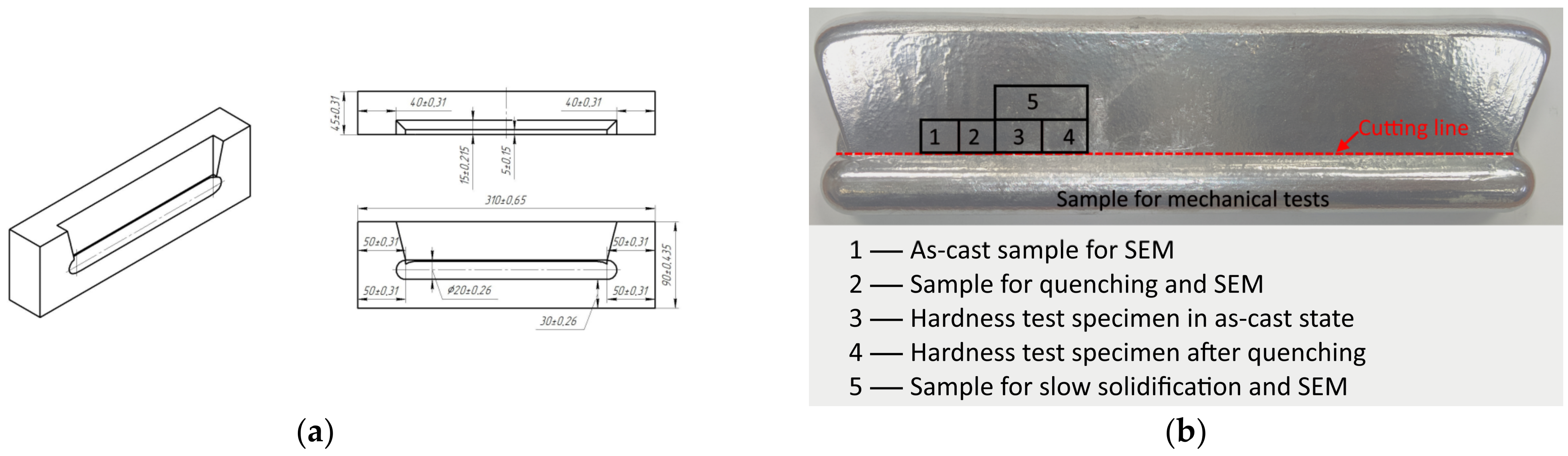
2.1. Alloys and Samples Preparation

The experimental alloys with compositions shown in Table 1 were prepared in an electric resistance furnace (GRAFICARBO GF 1100 N3DT, Zorlesco, Italy) from pure materials (Al (99.99%), Mg (99.9%) Ca (100%), Zn (99.9%)), and master alloys (Al-10%Fe, Al-20%Mn, Al-12%Si). The actual chemical compositions of the alloys were close to the nominal compositions, as determined by spectral analysis. The addition of alloying elements was carried out at 750 °C followed by regular stirring with a graphite stick to ensure adequate dissolution of high-melting point elements and homogeneous melt. Argon purging was applied as a melt-cleaning procedure. The melt was poured at 720 °C into the graphite mold schematically shown in Figure 1a. The mold was not preheated. The obtained component was a cylindrical bar with a riser, which ensured an adequate density. The bar was machined into the standard dog-bone cylindrical tensile samples according to the ASTM E8 standard. The experimental samples for microstructure and hardness characterization were cut from the riser. The plane facing the bar was examined (Figure 1b). Microstructure samples were prepared by grinding with SiC abrasive paper and polishing with 1 μm diamond suspension. Etching in 1% HF aqueous solution was used to improve the contrast.

2.2. Microstructure and Phase Transformations Analysis

The commonly used solution treatment temperature of Al-Mg-Mn alloys is the temperature near the nonequilibrium solidus, which is approximately 445 °C. In our study, a temperature of 440 °C was chosen. For a more accurate characterization of the structure components, the samples were melted and cooled slowly in the furnace. This procedure was supposed to bring us closer to the equilibrium conditions comparable with thermodynamic calculations. Also, after quenching, an artificial aging was carried out at 200 °C for 3 h to stimulate possible precipitation strengthening.
Characterization of microstructure was carried out using a scanning electron microscope (SEM, TESCAN VEGA3, Tescan Orsay Holding, Brno, Czech Republic) equipped with an energy dispersive microanalyzer (EDS, Oxford Instruments plc, Abingdon, UK) and a software Aztec version 3.3 SP1 (Oxford Instruments plc, Abingdon, UK).
X-ray diffraction (XRD) analysis was carried out on a Bede D1 System (Bruker, Karlsruhe, Germany) with Cu Kα radiation (λ = 0.15406 nm). Fine powder (up to 50 μm in diameter) milled from the part of the cast bars was examined by XRD.
The fine structure was observed using a transmission electron microscope JEM2100 (TEM, JEOL Ltd., Tokyo, Japan) at an accelerating voltage of 200 kV. Thin foils were prepared by mechanical polishing followed by thinning by ion polishing with a Struers device (Struers, Copenhagen, Denmark) at a voltage of 15 V and a temperature of −40 °C in a chlorine–alcohol electrolyte solution (C2H5OH with 10% HClO4).
Thermo-Calc version TCW5, database TTAL5 (Foundation for Computational Thermodynamics Stockholm, Sweden), was used for thermodynamic calculations [44], including liquidus projections, polythermal sections, and composition of phases at the room temperature (20 °C) and the temperature of solid solution treatment (440 °C). Non-equilibrium solidification was studied via the Scheil–Gulliver model, which assumes no diffusion in the solid but infinite diffusion in the liquid.

2.3. Physical and Mechanical Testing

Vickers hardness was measured using a Wilson Wolpert 930N hardness tester (Wilson Instruments, Instron Company, Norwood, MA, USA) under the load of 1 kg and dwell of 15 s. At least 10 measurements were carried out to obtain statistically representative results. Mechanical properties were determined by a uniaxial room temperature tensile test at a strain rate (cross-head speed) of 5 mm/min using a Zwick/Z 250 tensile frame (Zwick Roell AG, Ulm, Germany). For each condition, the test was repeated three times to ensure reproducibility.
The theoretical density was determined by calculating the compositions and mass fractions of the phases using Thermo-Calc software version TCW5, database TTAL5 (Foundation for Computational Thermodynamics, Stockholm, Sweden). The actual density was determined by hydrostatic weighing by sampling in the air ( m A ) and in water ( m w ) on an HR-202i (A&D RUS, Moscow, Russia) laboratory analytical scale.

3. Results

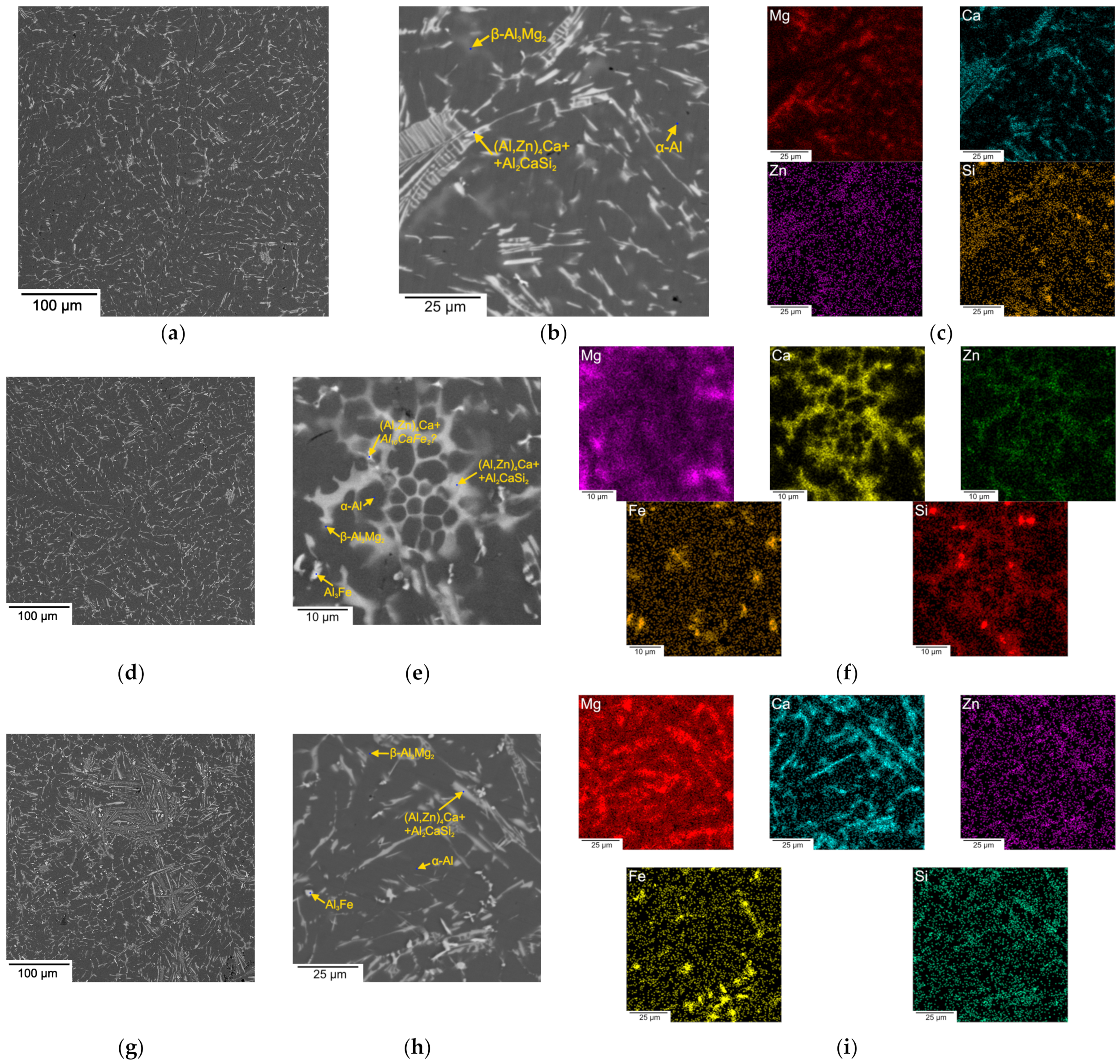
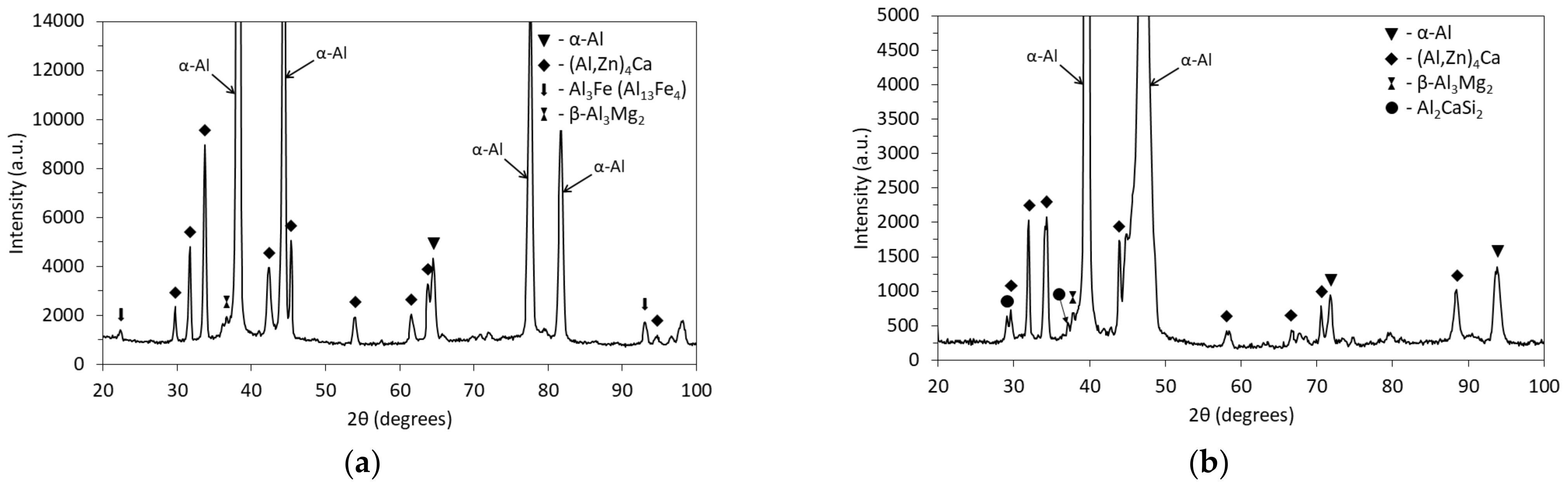
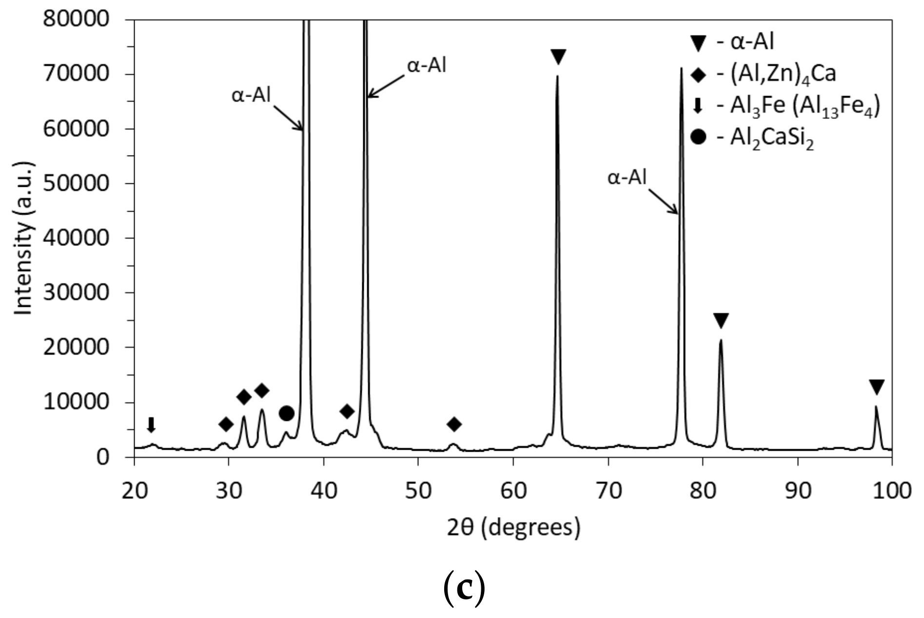
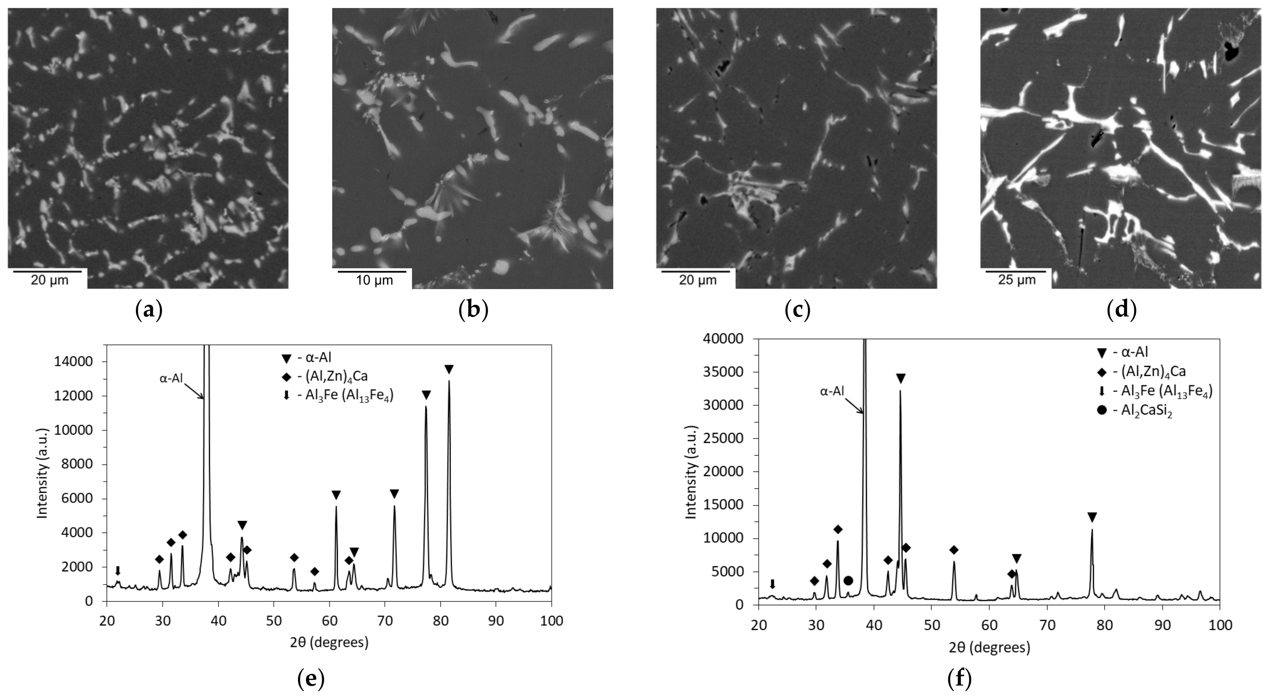
3.1. As-Cast Microstructure and Phase Identification

Figure 2 shows as-cast microstructures of the experimental alloys that contain a separate addition of Fe. They are all characterized by primary α-Al dendrites surrounded by the interconnected eutectic network, which is rich in Ca, Fe, Zn, and Mg, as confirmed by EDS elemental maps. Because of relatively fast cooling rates, the size factor plays a significant role during EDS point analysis, and phase identification can be challenging. However, a simultaneous presence of Zn and Ca in the composition of the eutectic suggests the formation of a eutectic intermetallic (Al, Zn)4Ca, according to the literature data [45,46,47,48] (Table 2). Phases containing both Mg and Zn were not found. Instead, Mg is likely to form a nonequilibrium Al3Mg2 phase, which is commonly found in commercial AA5xx alloys. Importantly, Fe-rich intermetallics drastically change morphology when the Fe content increases from 0.5 to 0.7% and 1%. In the 622F alloy (Figure 2a,b), Fe-rich intermetallics were formed within the compact eutectic mixture. In contrast, the 622F0.7 (Figure 2d,e) and 6221F (Figure 2f,g) alloys exhibit needle- and star-like intermetallics intrinsic to the Al3Fe phase. It should be noted that there is a negligible difference between dendritic arm spacings (10 ± 3 μm), which suggests similar solidification conditions.
Figure 3 shows the size distribution of intermetallic particles seen in the microstructure of as-cast 622F and 622S alloys. The Feret diameter is defined as the longest distance between two points in a cloud of pixels in a two-dimensional projection of intermetallic particles in the SEM image. It can be seen that the addition of Si sharply coarsens the morphology of the eutectic. Specifically, the number of small particles reduced, whereas the number of large particles increased.
A significant coarsening of microstructure in the alloy with the addition of 0.5%Si can be clearly seen in Figure 4a–c. Thin elongated intermetallics were found to contain large portions of Ca and Si, likely attributed to the presence of the Al2CaSi2 phase (Table 3) [37,49,50]. Similarly, this phase was found in other Al-Ca alloys with Si addition [51,52]. The solubility of Si is limited in high Mg alloys; therefore, all Si entered Ca-rich intermetallics, as confirmed by the corresponding elemental maps. Meanwhile, eutectic α-Al + (Al, Zn)4Ca appeared much coarser compared to that in the as-cast alloy with 0.5%Fe. In both cases, the formation of a Ca-rich eutectic network starts with the initiation of the primary phase; then, the formation of binary eutectic and should end with ternary eutectic reactions L → α-Al + Al4Ca + Al10CaFe2 and L → α-Al + Al4Ca + Al2CaSi2. The fraction of this ternary eutectic might influence the morphology of the intermetallic particles in the network. Considering the finer morphology of particles in the 622Fe alloy, we assume that the addition of 0.5%Fe allows us to have a larger fraction of the ternary eutectic compared to the addition of 0.5%Si.
The combined addition of 0.5%Fe and 0.5%Si also resulted in the formation of elongated intermetallics similar to that in the 622S alloy (Figure 4d). However, (Al,Zn)4Ca intermetallics seem to be more compact. They were occasionally found in the form of “sponge” conglomerates (Figure 4e), which may be more favorable than skeleton eutectic shown in Figure 4b. EDS elements maps indicate that the sponge-like eutectic network is enriched in Ca and Zn along with Fe within the light particles (Figure 4f). Whereas Si can be observed in the multiphase eutectic mixture, the individual Al2CaSi2 or Mg2Si could hardly be detected. Mg is distributed between α-Al and Al3Mg2. Because of the small amount of Mg in the eutectic, we assume that the peritectic reaction L + Al2CaSi2 → L + Mg2Si was suppressed. Similar suppression also occurred in the 622S alloy. Thus, in the as-cast Si-containing alloys, the microstructure consists of α-Al dendrites decorated by (Al,Zn)4Ca + Al2CaSi2 eutectic with a composition given in Table 3. The presence of Mg, Ca, and Zn in the phases with Fe can be explained by the size effect. In the 622F1S alloy, eutectic is as coarse as in the 622S alloy, likely because of the appearance of the primary Al3Fe phase, which has a needle-like and rarely compact morphology (Figure 4g,h). Interestingly, the Fe-rich intermetallics in the alloy with 1%Fe maintain a smaller size than (Al,Zn)4Ca and Al2CaSi2 intermetallics in the alloys with only Si addition.
XRD analysis of as-cast 622F (Figure 5a), 622S (Figure 5b), and 622FS (Figure 5c) alloys confirmed the SEM/EDS observations except for the possible appearance of the Al10CaFe2 phase. The corresponding XRD profiles reveal (Al) peaks of different widths that might be attributed to the uncontrolled microstrain that appeared as a result of a powder preparation. The Al4Ca compound was readily found in all alloys, whereas the Fe-containing alloys clearly showed an Al3Fe compound, and the Si-containing alloys the Al2CaSi2 compound. The β-Al3Mg2 phase was also identified, but the peaks were too small, which can be attributed to a small fraction of this phase.

3.2. Microstructure and Phase Composition of Solid Solution-Treated Alloys

The microstructure of the solution-treated alloys is given in Figure 6. It can be seen that eutectic intermetallics are more prone to spheroidization in Fe-containing alloys than in Si-containing alloys. This is likely attributed to the high thermal stability of eutectic particles and a coarse as-cast morphology of the Al2CaSi2 intermetallics. The β-Al3Mg2 could not be observed in the microstructure nor detected by XRD (Figure 6e,f), signifying that Mg dissolved in the α-Al solid solution. The composition of α-Al is presented in Table 4. All alloys have nearly identical Mg solute content, which is close to the Mg content in the alloys’ chemical composition. This confirms that no Mg is bound in intermetallics with Ca, Si, or Fe. Meanwhile, Zn is still distributed between α-Al and (Al,Zn)4Ca intermetallics. Comparing the compositions of (Al,Zn)4Ca in as-cast (Table 2) and solution-treated states (Table 3), it can be found that more Zn dissolves in these intermetallics after heat treatment. During EDS analysis, some Si was found in the (Al,Zn)4Ca phase, suggesting a close arrangement with the Al2CaSi2 phase during solidification.

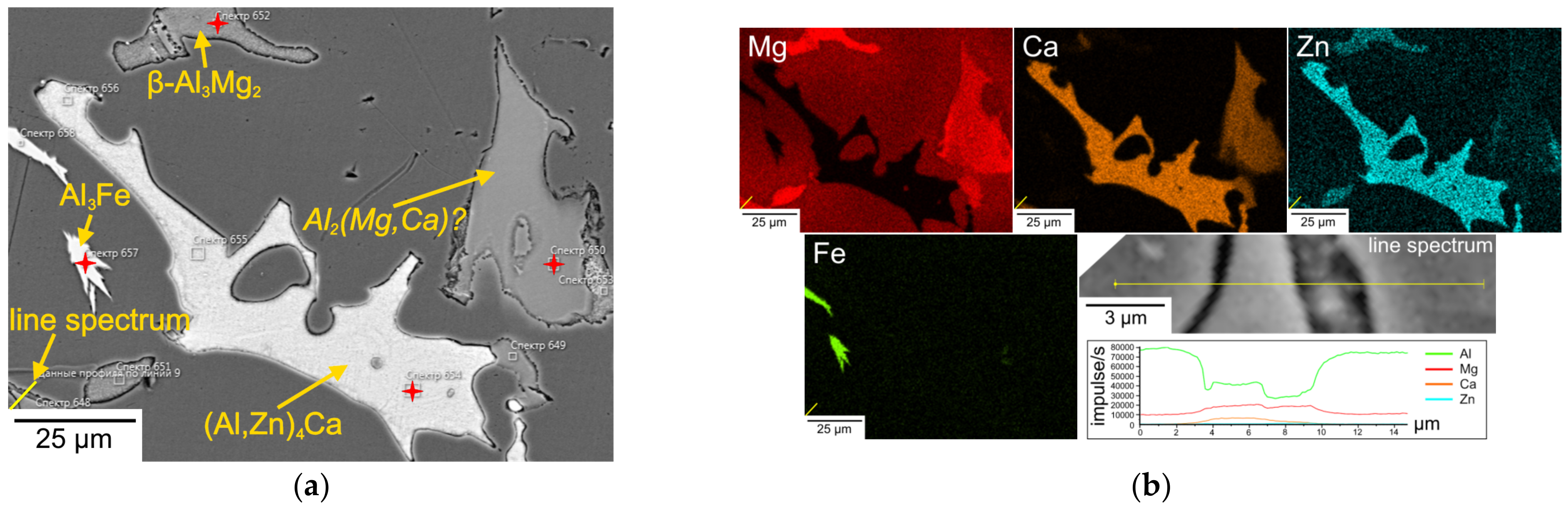
3.3. Investigation of the Microstructure of the Slowly Solidified Alloys

The SEM microstructures of slowly solidified samples were combined with EDS elemental maps (Figure 7). A significant increase in the size of all phases compared to cast samples was found. A larger size may allow for providing a more reliable phase identification. In all Fe-containing alloys, skeleton-like crystals of (Al,Zn)4Ca phase decorate the α-Al matrix. A light BSE contrast of these intermetallics suggests a high content of dissolved Zn. Light-elongated and star-shaped crystals corresponding to the Al3Fe intermetallics were found even in the 622F alloy, whereas they were not very pronounced in the cast alloys. The only difference between the alloys containing 0.5% and 1% Fe is the size of the Al3Fe intermetallics. Thus, it can be assumed that the possible peritectic reaction L + Al3Fe → L + Al10CaFe2 at concentrations of 0.5–1% Fe and 6% Mg is suppressed at low cooling rates. Since no Mg2Si could be found, a peritectic reaction L + Al2CaSi2 → L + Mg2Si was also suppressed. Si is often found close to the compound (Al,Zn)4Ca. This may suggest that the Al2CaSi2 intermetallic serves as a substrate for the crystallization of the (Al,Zn)4Ca intermetallic. This assumption may explain the elongated shape of (Al,Zn)4Ca intermetallics in the as-cast microstructure and their complex composition.
Two types of phases with a similar BSE contrast forming a single conglomerate may deserve special attention. EDS elemental mapping and point analysis (Table 5) indicate that one of them contains an appreciable amount of Mg and Zn, suggesting the (Al,Zn)3Mg2 phase. The other part of this conglomerate contains Mg and Ca. Its stoichiometric composition may suggest the compound Al2(Mg,Ca). Meanwhile, the homogeneous range of this compound is probably narrow because the Mg atomic concentration is about three times higher than Ca. As these conglomerates are in contact with (Al,Zn)4Ca in some places, a mechanism for their nucleation and growth can be assumed. The formation probably takes place at the moment of Mg and Zn solute pile-up, followed by the formation of the non-equilibrium (Al,Zn)3Mg2 phase on another eutectic phase (Al,Zn)4Ca, which may serve as a substrate. As a result, due to the activity of Mg, the Mg atoms are replaced by Ca atoms, followed by a change in the crystal lattice.
The hardness is improved by the addition of Fe, whereas it drops after the addition of Si (Figure 8a). The tensile tests were carried out for the solution-treated alloys 622F, 622S, and 622FS (Figure 8b). Accordingly, the 622S alloy has the smallest yield strength, whereas the 622F has the largest yield strength. There is a slight increment in yield strength after the combined addition of 0.5%Fe and 0.5%Si. The results suggest that Fe-containing alloys can contain more solute, contributing to yield strength. Similarly, the ultimate tensile strength is much smaller in 622S and 622FS alloys than in the 622F alloy, which is probably because the Si-containing alloys start necking earlier due to a coarser eutectic. One should note that the base alloy without Fe and Si has relatively higher ductility compared to the investigated alloys. The lower elongation could be explained by an increased total fraction of intermetallics as well as the coarse morphology of Al3Fe and Al2CaSi2 phases.

4. Discussion

4.1. Liquidus Surfaces of the Al-Mg-Ca-Zn-(Fe)-(Si) System

The liquidus surfaces in the Al-Mg-Ca-Zn-Fe system (Figure 9a) at 2%Zn and 0.5%Fe show three equilibrium regions corresponding to the α-Al, (Al,Zn)4Ca, and Al3Fe phases. It can be seen that in this system, the boundary of the appearance of the primary (Al,Zn)4Ca phase is shifted toward α-Al, which is contrary to the Al-Ca binary system [37]. Meanwhile, the region for the existence of the primary Al3Fe phase is limited to alloys containing up to 5% Ca and 0.5–0.9%Fe (Figure 9b). In the alloys with a total Mg + Ca ≤ 4, the primary crystallization region for α-Al (dotted line in Figure 9a) decreases considerably with increasing Fe up to 1%. Al-Ca alloys with up to 2%Mg and 0.5%Si will begin their solidification from the formation of a ternary Al2CaSi2 phase (Figure 9c). The liquidus surface of the Al-Mg-Ca-Zn-Fe-Si system as a function of Si and Ca concentrations (Figure 9d) shows that the primary crystallization of Al2CaSi2 happens at relatively large Ca and Si concentrations. At the constant Si, an increase in Ca promotes the appearance of primary Al3Fe and Al4Ca phases. It can be seen in Figure 9e that at 2%Ca, the Si content can be high enough without the risk of significant enlargement of the primary crystallization region and that this concentration does not influence the Fe limit of 0.7%. On the contrary, it changes the area of the primary crystallization phase regions to a large extent, as shown in Figure 9f. Thus, we have found out that the experimental alloys were not supposed to have any primary crystals apart from the Al3Fe in the 622F1, which was confirmed accordingly in the slowly solidified microstructure.

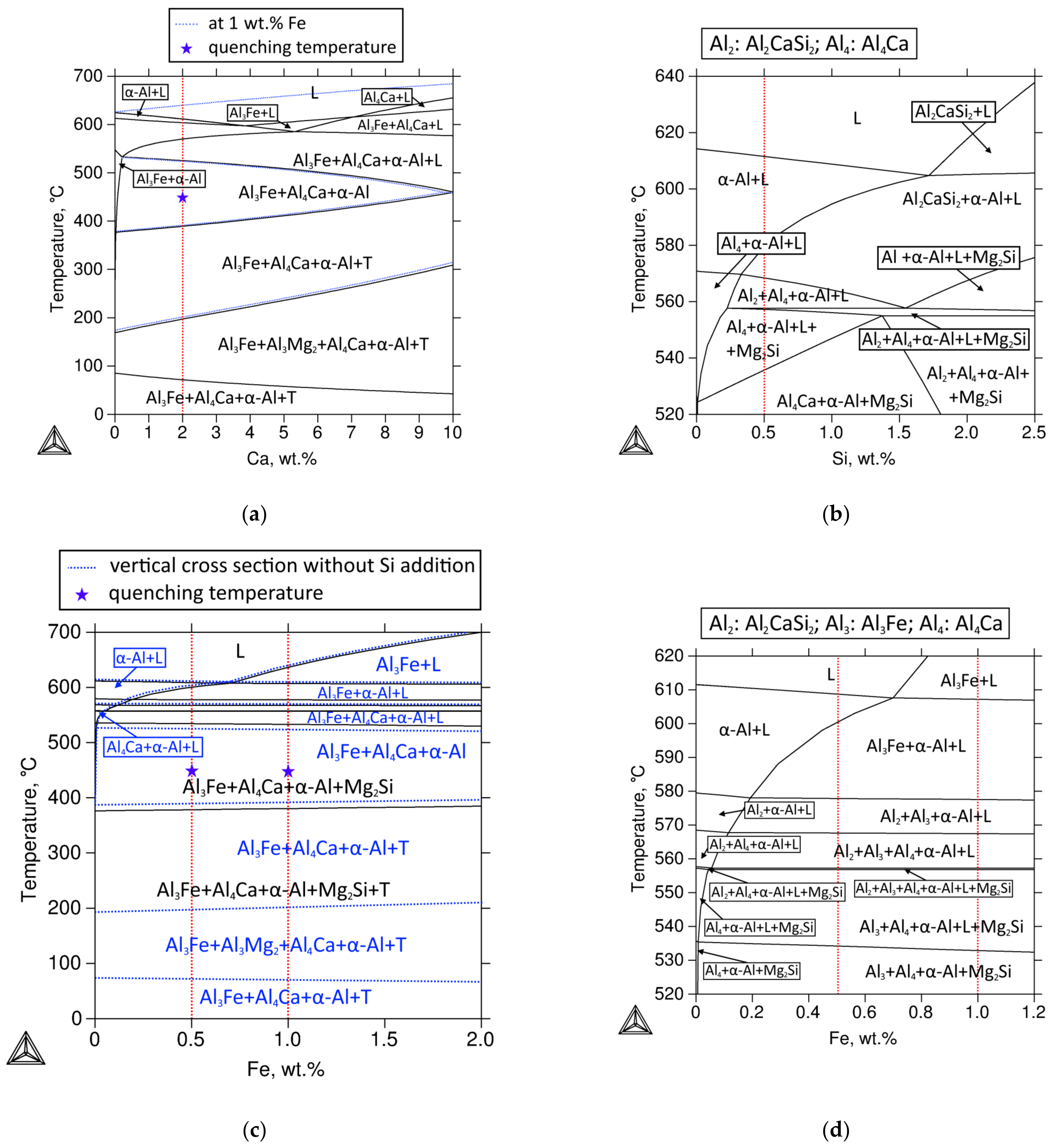
4.2. Polythermal Phase Diagram Cross-Section Calculation for Investigated Alloys of Multicomponent Systems Al-Mg-Ca-Zn-Fe-Si

The polythermal section of Figure 10a shows that 0.5%Fe is optimal to avoid the formation of Fe-rich primary crystals because a high Mg content allows for the shift of the primary crystallization area toward α-Al [4]. In this case, even up to 0.7% Fe does not affect the liquidus temperature, which remains almost unchanged (611 °C) (Figure 8c—blue dotted lines). The equilibrium solidification ends at about 525 °C, in the region of ternary L → Al3Fe + Al4Ca + α-Al eutectic. The polythermal section of the Al-Mg-Ca-Zn-Si system (Figure 10b) seems to be more complex than the Al-Mg-Ca-Zn-Fe system because there are twice as many regions in equilibrium in the temperature interval of 500–600 °C. Specifically, the horizontal line at ~560 °C corresponds to the mono variant (interval smaller than 1 C at 0.5% Si) peritectic reaction L + Al2CaSi2 → L + Mg2Si. As a result of this reaction, the Al2CaSi2 phase disappears, and crystallization continues in the three-phase region. In the alloys containing a small amount of Si, this transformation does not happen. Similarly to the Al-Mg-Ca-Zn-Fe alloys, the crystallization ends in the four-phase region α-Al + Al3Fe + Al4Ca + Mg2Si + T-(Mg32(AlZn)49)). The polythermal section of the Al-Mg-Ca-Zn-Fe-Si diagram on the Fe side (black lines in Figure 10c) is similar to the system without Si. The only difference is in the formation of the peritectic reaction L + Al2CaSi2 → L + Mg2Si, after which the liquid phase can still be observed. The alloys with a small Fe content should not contain the Al3Fe phase, and there is also no peritectic reaction. If more than 0.7%Fe is present in the alloy, the crystallization should start with the formation of the Al3Fe phase, after which the crystallization proceeds similarly to the alloys, either with or without Si.

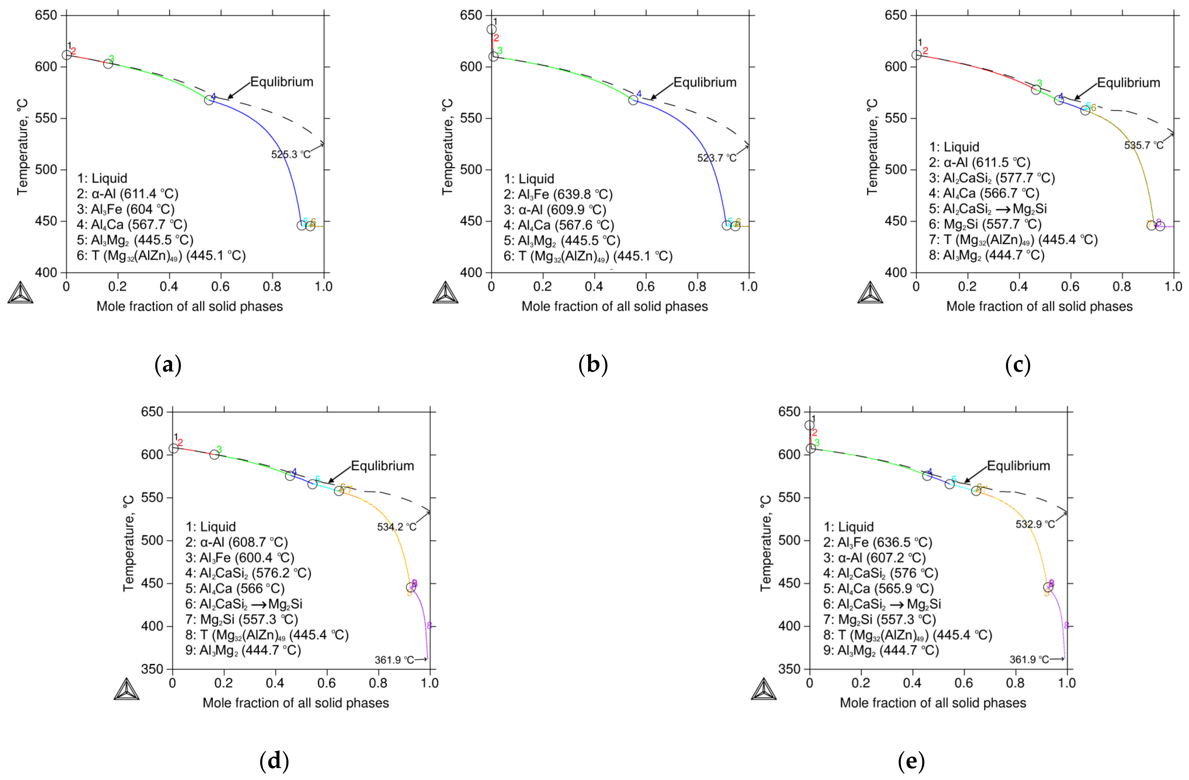
4.3. Non-Equilibrium Crystallisation of the Experimental Alloys According to the Scheil–Gulliver Model

A slight reduction in liquidus temperature after the addition of Fe in the base alloy has been reported [41]. The real solidification ends in the four-phase region Al3Fe + Al4Ca + α-Al + T-(Mg32(AlZn)49). The critical temperatures of equilibrium and nonequilibrium crystallization are shown in Figure 11.

4.4. Calculated Phase Composition

All alloys have approximately the same fraction of second phases, which is about 25% (Table 6). The fraction of (Al,Zn)4Ca, T-(Mg32(AlZn)49), and Mg2Si phases in all alloys is constant, except for alloys 622F and 622F1, which have a smaller amount of the Mg-containing phases. For alloys containing more than 5% Mg, homogenization at 440 °C is the most commonly used temperature [4]. The phase composition of all alloys at this temperature does not contain excess phase T-(Mg32(AlZn)49). This leads to the formation of α-Al supersaturated solid solution.

4.5. Analysis of Samples after Quenching and Artificial Ageing

The samples subjected to artificial aging were studied to confirm the absence of hardening T’-(Mg32(AlZn)49) precipitates due to lack of Zn. One should expect an increase in hardness as a result of the formation of Zn-containing precipitates. However, based on the results of the Vickers hardness measurements, we found a slight decrease in hardness values compared to the solution-treated state (Table 6). We associate this fact with the decrease in Mg content in α-Al and precipitation of β-Al3Mg2 metastable precursors, which do not bring any strengthening effect [53]. These crystals can be seen in the SEM image shown in Figure 12a. EDS point analysis confirms the correspondence of the atomic ratio of Mg and Al to the β-Al3Mg2 phase (Figure 12b). The concentration of dissolved Zn in this compound corresponds to the data from [37]. The β-Al3Mg2 with a linear size of 50–100 nm can be seen along the grain boundaries and inside the α-Al matrix in the light and dark field TEM images shown in Figure 12d–g. The diffraction pattern confirms the crystal lattice of the β-Al3Mg2 phase.
Based on the calculated data, the phase composition appears to be quite complex. The experimental results do not necessarily comply with the equilibrium calculations and the Scheil–Gulliver model. The real and calculated phase composition has been most accurately determined in the Al-Mg-Ca-Zn-Fe five-phase system. Previous studies [21,24,36,38] suggested the existence of a ternary intermetallic Al10CaFe2 formed by the peritectic reaction L + Al3Fe → (α-Al) + Al10CaFe2 but could not find reliable confirmation. T-(Mg32(AlZn)49) is also missing because of significant Zn solubility in α-Al and (Al,Zn)4Ca phase. This results in the formation of an excessive amount of non-equilibrium eutectic phase β-Al3Mg2. In the alloys with Ca, the expected peritectic reaction L + Al2CaSi2 → L + Mg2Si is completely suppressed, and, therefore, we detected only one Si-bearing intermetallic, Al2CaSi2, in the microstructure. Thus, the theoretical analysis performed agrees well with the experimental results with a remark for the incompleteness of peritectic reactions.
As can be seen from the results in Table 7, the alloy with 0.5%Fe has the most favorable combination of mechanical properties, which are similar to the base alloy 622 [23,54]. Compared with the standard cast alloys, such as 512.0 or 535.0, the 622F alloy has either similar or higher values (Table 7). Based on the results of the qualitative and quantitative evaluation of the microstructure and mechanical properties, we conclude that Al-6%Mg-2%Ca-2%Zn doped with 0.5%Fe is optimal in terms of the fragmented eutectic particles after solid solution treatment, superior mechanical properties, and low density which are summarized in Table 6. Based on the comparison of qualitative microstructure parameters and non-equilibrium crystallization data (Figure 11a) with the original alloy from [54], it may be assumed that alloy 622F can have a similar level of casting properties, which is a subject of future study.

5. Conclusions

  • Using Thermo-Calc software, the phase diagram of the Al-Mg-Ca-Zn-Fe-Si system has been constructed. The qualitative and quantitative phase composition of the investigated alloys and their critical temperatures have been determined. The alloys with up to 0.7%Fe should not contain the primary Al3Fe phase. The total calculated mass fraction of all phases in all investigated alloys was more than 25%. Except for the peritectic reactions, the experimental results agreed with the calculations;
  • The alloy Al-6%Mg-2%Ca-2%Zn-0.5%Fe was found to have a microstructure containing an ultrafine multiphase eutectic. The alloy also showed superior mechanical properties compared to the Si-containing alloys and some standard alloys. The Fe-containing intermetallics were finely incorporated in the eutectic, and their sizes did not exceed 3 µm. A higher Fe concentration leads to the formation of primary Al3Fe crystals whose sizes are even smaller than those of the Al2CaSi2 phase found in the Si-containing alloys;
  • In the microstructure of slowly solidified Al-6%Mg-2%Ca-2%Zn-0.5%Fe alloy, the ternary Al10CaFe2 intermetallic was not revealed. This indicates that the possible peritectic reaction L + Al3Fe → α-Al + Al10CaFe2 does not take place in the considered range of Mg, Ca, and Fe concentrations;
  • The Si-containing alloys show coarser eutectic, which was characterized by needle-shaped elongated colonies. EDS analysis showed the presence of Ca, Zn, and Si, which allowed us to identify (Al,Zn)4Ca and Al2CaSi2 intermetallics. Since no other phases with Si were found, we can conclude that the peritectic reaction L + Al2CaSi2 → L + Mg2Si was suppressed;
  • The complex composition of (Al,Zn)4Ca + Al2CaSi2 intermetallics mixture suggests that the aluminide Al2CaSi2, due to earlier crystallization, could be a substrate for the other intermetallic phases with Ca, resulting in their coarser morphology. Assumingly, the higher brittleness of such a complex compound leads to lower mechanical properties (YS 131 MPa versus 146 MPa in 622S and 622F, respectively) and ductility.

Author Contributions

Methodology, V.D., T.S., A.F. and I.S.; formal analysis, V.D.; investigation, T.S., A.F. and I.S.; writing—original draft, V.D.; writing—review and editing, P.S.; visualization, V.D. All authors have read and agreed to the published version of the manuscript.

Funding

The authors gratefully acknowledge the financial support of the Russian Science Foundation (Project No. 23-79-01055 https://rscf.ru/project/23-79-01055/) (SEM, XRD analysis, hardness, tensile tests) and financial support by the Moscow Polytechnic University within the framework of the grant named after Pyotr Kapitsa (Conceptualization, SEM, TEM, Thermo-Calc calculations, discussion).

Data Availability Statement

Not applicable.

Acknowledgments

The authors are grateful to Nikolai Belov (NUST MISiS) for his valuable suggestions in the preparation of this article. The results were obtained by using the equipment of the Center for Collective Use, “Materials Science and Metallurgy”, with the financial support of the Ministry of Science and Higher Education of the Russian Federation (#075-15-2021-696).

Conflicts of Interest

The authors declare no conflict of interest.

References

  1. Belov, N.A.; Zolotorevskij, V.S. The effect of nickel on the structure, mechanical and casting properties of aluminium alloy of 7075 type. Mater. Sci. Forum 2002, 396–402, 935–940. [Google Scholar] [CrossRef]
  2. Mann, V.K.; Alabin, A.N.; Krokhin, A.Y.; Frolov, A.V.; Belov, N.A. New generation of high strength aluminum casting alloys. Light Met. Age 2015, 73, 44–47. [Google Scholar]
  3. Lin, J.C.; Glazoff, M.V.; Zolotorevsky, V.S.; Murtha, S.J.; Belov, N.A. An Al–Ni–Mn Casting Alloy for Automotive and Aerospace Structural Components. U.S. Patent 6,783,730, 31 August 2004. [Google Scholar]
  4. Glazoff, M.; Khvan, A.; Zolotorevsky, V.; Belov, N.; Dinsdale, A. Casting Aluminum Alloys: Their Physical and Mechanical Metallurgy, 2nd ed.; Elsevier: London, UK, 2018; p. 608. [Google Scholar]
  5. Mo, L.; Zhou, X.; Liu, X.; Zhan, M.; Zhao, Y.-J.; Du, J. Microstructure and thermal-physical properties of hypereutectic Al-Ni alloys. J. Mater. Res. Technol. 2023, 24, 6227–6237. [Google Scholar] [CrossRef]
  6. Jiang, M.; Mo, L.; Zhou, X.; Liu, X.; Zhan, M.; Du, J. Microstructure Evolution and Thermophysical Properties of Hypereutectic Al-Fe-Ni Alloys. Int. Metalcast. 2023. [Google Scholar] [CrossRef]
  7. Babilas, R.; Młynarek-Żak, K.; Łoński, W.; Łukowiec, D.; Lis, M.; Kądziołka-Gaweł, M.; Warski, T.; Radoń, A. Influence of Fe, Cr, and Cu addition on the microstructure, hardness, and anticorrosion properties of Al–Ni–Y alloys. Arch. Civ. Mech. Eng. 2022, 22, 82. [Google Scholar] [CrossRef]
  8. Su, Z.; Xiao, Z.; Zeng, Z.; Jiang, B.; Ma, C.; Yang, P.; Wang, Y.; Xu, S. Microstructure and mechanical properties of squeeze-cast Al-5.0Cu-1Mn-based alloys with different Ni content. Mater. Des. 2023, 229, 111901. [Google Scholar] [CrossRef]
  9. Rogachev, S.O.; Naumova, E.A.; Lukina, E.A.; Zavodov, A.V.; Khatkevich, V.M. High Strength Al–La, Al–Ce, and Al–Ni Eutectic Aluminum Alloys Obtained by High-Pressure Torsion. Materials 2021, 14, 6404. [Google Scholar] [CrossRef]
  10. Akopyan, T.K.; Belov, N.A.; Naumova, E.A.; Letyagin, N.V. New in-situ Al matrix composites based on Al-Ni-La eutectic. Mater. Lett. 2019, 245, 110–113. [Google Scholar] [CrossRef]
  11. Belov, N.A.; Naumova, E.A.; Eskin, D.G. Casting alloys of the Al–Ce–Ni system: Microstructural approach to alloy design. Mater. Sci. Eng. A 1999, 271, 134–142. [Google Scholar] [CrossRef]
  12. Shen, S.; Wu, C.; Li, Y.; Huang, Y.; Huang, W.; Zhang, P.; Zhong, S.; Lu, Y.; Luo, G.; Gan, Z.; et al. Refining mechanism and elevated-temperature mechanical properties of Al-Ce alloys solidified under super gravity field. Mater. Sci. Eng. A 2023, 879, 145191. [Google Scholar] [CrossRef]
  13. Yi, M.; Zhang, P.; Yang, C.; Cheng, P.; Guo, S.; Liu, G.; Sun, J. Improving creep resistance of Al-12 wt.% Ce alloy by microalloying with Sc. Scr. Mater. 2021, 198, 113838. [Google Scholar] [CrossRef]
  14. He, Y.; Liu, J.; Qiu, S.; Deng, Z.; Zhang, J.; Shena, Y. Microstructure evolution and mechanical properties of Al-La alloys with varying La contents. Mater. Sci. Eng. A 2017, 701, 134–142. [Google Scholar] [CrossRef]
  15. Kozakevich, J.R.; Stroh, J.; Sediako, D.; Weiss, D. Solidification Kinetics of an Al-Ce Alloy with Additions of Ni and Mn. Metals 2023, 13, 955. [Google Scholar] [CrossRef]
  16. Deev, V.; Prusov, E.; Shurkin, P.; Ri, E.; Smetanyuk, S.; Chen, X.; Konovalov, S. Effect of La Addition on Solidification Behavior and Phase Composition of Cast Al-Mg-Si Alloy. Metals 2020, 10, 1673. [Google Scholar] [CrossRef]
  17. Rogachev, S.O.; Naumova, E.A. Thermal Stability of Al-Ca and Al-Ce Alloys Obtained by High-Pressure Torsion. J. Mater. Eng. Perform. 2021, 30, 9192–9199. [Google Scholar] [CrossRef]
  18. Akopyan, T.K.; Letyagin, N.V.; Avxentieva, N.N. High-tech alloys based on Al–Ca–La(–Mn) eutectic system for casting, metal forming and selective laser melting. Non-Ferr. Met. 2020, 48, 52–59. [Google Scholar] [CrossRef]
  19. Naumova, E.; Doroshenko, V.; Barykin, M.; Sviridova, T.; Lyasnikova, A.; Shurkin, P. Hypereutectic Al-Ca-Mn-(Ni) Alloys as Natural Eutectic Composites. Metals 2021, 11, 890. [Google Scholar] [CrossRef]
  20. Wu, Z.; Zhang, H.; Tang, S.; Zou, J.; Yang, D.; Wang, Y.; Qin, K.; Ban, C.; Cui, J.; Nagaumi, H. Effect of calcium on the electrochemical behaviors and discharge performance of Al–Sn alloy as anodes for Al–air batteries. Electrochim. Acta 2021, 370, 137833. [Google Scholar] [CrossRef]
  21. Rogachev, S.O.; Zavodov, A.V.; Naumova, E.A.; Chernenok, T.V.; Lukina, E.A.; Zadorozhnyy, M.Y. Improvement of strength–ductility balance of Al–Ca–Mn–Fe alloy by severe plastic deformation. Mater. Lett. 2023, 349, 134797. [Google Scholar] [CrossRef]
  22. Zhang, S.; Du, H.; Yao, Z.; Liu, Z.; Zhu, Y.; Shuai, L.; Huang, T.; Huang, X.; Tao, X.; Mondal, D.P.; et al. Superior high temperature creep resistance of a cast Al–Mg–Ca-Sc alloy with multi-scale hierarchical microstructures. Mater. Sci. Eng. A 2022, 850, 143533. [Google Scholar] [CrossRef]
  23. Doroshenko, V.V.; Barykin, M.A.; Vasina, M.A.; Aksenov, A.A. Combined effect of calcium and zinc on the hot cracking of Al–Mg alloys. Tsvetnye Met. 2022, 12, 48–57. [Google Scholar] [CrossRef]
  24. Letyagin, N.V.; Musin, A.F.; Sichev, L.S. New aluminum-calcium casting alloys based on secondary raw materials. Mater. Today Proc. 2021, 38, 1551–1555. [Google Scholar] [CrossRef]
  25. Glavatskikh, M.V.; Barkov, R.Y.; Gorlov, L.E.; Khomutov, M.G.; Pozdniakov, A.V. Novel Cast and Wrought Al-3Zn-3Mg-3Cu-Zr-Y(Er) Alloys with Improved Heat Resistance. Metals 2023, 13, 909. [Google Scholar] [CrossRef]
  26. Shen, G.; Chen, X.; Yan, J.; Fan, L.; Yang, Z.; Zhang, J.; Guan, R. A Review of Progress in the Study of Al-Mg-Zn(-Cu) Wrought Alloys. Metals 2023, 13, 345. [Google Scholar] [CrossRef]
  27. Shen, G.; Xiang, Z.; Ma, X.; Huang, J.; Zhao, Y.; Li, J.; Wang, Z.; Shi, G.; Chen, Z. Investigation of Microstructures and Mechanical Properties of Ultra-High Strength Al-Zn-Mg-Cu Alloy Prepared by Rapid Solidification and Hot Extrusion. Metals 2023, 13, 293. [Google Scholar] [CrossRef]
  28. Hsiao, T.-J.; Chiu, P.-H.; Tai, C.-L.; Tsao, T.-C.; Tseng, C.-Y.; Lin, Y.-X.; Chen, H.-R.; Chung, T.-F.; Chen, C.-Y.; Wang, S.-H.; et al. Effect of Cu Additions on the Evolution of Eta-prime Precipitates in Aged AA 7075 Al–Zn–Mg–Cu Alloys. Metals 2022, 12, 2120. [Google Scholar] [CrossRef]
  29. Khomutov, M.G.; Pozdniakov, A.V.; Glavatskikh, M.V.; Barkov, R.Y.; Churyumov, A.Y.; Travyanov, A.Y. Effect of Thermal Deformation Treatment Regimes on Al–4.5Zn–4.5Mg–1Cu–0.12Zr–0.1Sc Alloy Structure and Properties. Metallurgist 2023, 66, 1225–1234. [Google Scholar] [CrossRef]
  30. Plotkowski, A.; Rios, O.; Sridharan, N.; Sims, Z.; Unocic, K.; Ott, R.T.; Dehoff, R.R.; Babu, S.S. Evaluation of an Al-Ce alloy for laser additive manufacturing. Acta Mater. 2017, 126, 507–519. [Google Scholar] [CrossRef]
  31. Zhang, X.; Li, L.; Wang, Z.; Peng, H.; Gao, J.; Peng, Z. A novel high-strength Al-La-Mg-Mn alloy for selective laser melting. J. Mater. Sci. Technol. 2023, 137, 205–214. [Google Scholar] [CrossRef]
  32. Shurkin, P.K.; Letyagin, N.V.; Yakushkova, A.I.; Samoshina, M.E.; Ozherelkov, D.Y.; Akopyan, T.K. Remarkable thermal stability of the Al-Ca-Ni-Mn alloy manufactured by laser-powder bed fusion. Mater. Lett. 2021, 285, 129074. [Google Scholar] [CrossRef]
  33. Plotkowski, A.; Sisco, K.; Bahl, S.; Shyam, A.; Yang, Y.; Allard, L.; Nandwana, P.; Rossy, A.M.; Dehoff, R.R. Microstructure and properties of a high temperature Al–Ce–Mn alloy produced by additive manufacturing. Acta Mater. 2020, 196, 595–608. [Google Scholar] [CrossRef]
  34. Rogachev, S.O.; Naumova, E.A.; Komissarov, A.A.; Vasina, M.A.; Pavlov, M.D.; Tokar’, A.A. Effect of Laser Surface Modification on the Structure and Mechanical Properties of Al–8% Ca, Al–10% La, Al–10% Ce, and Al–6% Ni Eutectic Aluminum Alloys. Russ. J. Non-Ferr. Met. 2022, 63, 671–680. [Google Scholar] [CrossRef]
  35. Ha, S.H.; Yoon, Y.O.; Kim, B.H.; Lim, H.K.; Lee, T.W.; Lim, S.H.; Kim, S.K. Oxide Scale Behavior and Surface Protection of Al–Mg Alloys Containing a Trace of Ca. Int. J. Metalcast. 2019, 13, 121–129. [Google Scholar] [CrossRef]
  36. Belov, N.A.; Naumova, E.A.; Akopyan, T.K. Eutectic Alloys Based on Aluminum: New Systems and Alloying. Ore and Metals: Moscow, Russia, 2016; p. 256. [Google Scholar]
  37. Mondolfo, L.F. Aluminum Alloys: Structure and Properties; Butterworths: Boston, London, 1976; p. 982. [Google Scholar]
  38. Shurkin, P.K.; Dolbachev, A.P.; Naumova, E.A.; Doroshenko, V.V. Effect of iron on the structure, hardening and physical properties of the alloys of the Al–Zn–Mg–Ca system. Tsvet. Met. 2018, 5, 69. [Google Scholar] [CrossRef]
  39. Naumova, E.A. Use of Calcium in Alloys: From Modifying to Alloying. Russ. J. Non-Ferr. Met. 2018, 59, 284–298. [Google Scholar] [CrossRef]
  40. Zolotorevskii, V.S.; Pozdnyakov, A.V.; Churyumov, A.Y. Search for promising compositions for developing new multiphase casting alloys based on Al-Cu-Mg matrix using thermodynamic calculations and mathematic simulation. Phys. Met. Metallogr. 2012, 113, 1052–1060. [Google Scholar] [CrossRef]
  41. Yun, J.; Kang, S.; Lee, D.; Bae, D. Development of heat-treatable Al-5Mg alloy sheets with the addition of Zn. Mater. Sci. Eng. A 2019, 744, 21–27. [Google Scholar] [CrossRef]
  42. Zhao, J.-W.; Luo, B.-H.; He, K.-J.; Bai, Z.-H.; Li, B.; Chen, W. Effects of minor Zn content on microstructure and corrosion properties of Al−Mg alloy. J. Cent. South Univ. 2016, 23, 3051–3059. [Google Scholar] [CrossRef]
  43. Wasiur-Rahman, S.; Medra, M. A thermodynamic description of the Al-Ca-Zn ternary system. Calphad 2009, 33, 584–598. [Google Scholar] [CrossRef]
  44. Thermo-Calc Software TTAL5 Al-Alloys. Available online: www.thermocalc.com (accessed on 10 March 2023).
  45. Moore, D.M.; Morris, L.R. A new superplastic aluminum sheet alloy. Mater. Sci. Eng. 1980, 43, 85–92. [Google Scholar] [CrossRef]
  46. Swaminathan, K.; Padmanabhan, K.A. Tensile flow and fracture behaviour of a superplastic Al—Ca—Zn alloy. J. Mater. Sci. 1990, 25, 4579–4586. [Google Scholar] [CrossRef]
  47. Perez-Prado, M.T.; Cristina, M.C.; Ruano, O.A.; Gonza, G. Microstructural evolution of annealed Al—5%Ca—5% Zn sheet alloy. J. Mater. Sci. 1997, 32, 1313–1318. [Google Scholar] [CrossRef]
  48. Kono, N.; Tsuchida, Y.; Muromachi, S.; Watanabe, H. Study of the AlCaZn ternary phase diagram. Light Met. 1985, 35, 574–580. [Google Scholar] [CrossRef]
  49. Belov, N.A.; Naumova, E.A.; Doroshenko, V.V.; Korotkova, N.O. Phase Composition, Structure, and Hardening of Alloys Containing 6% (Ca + Si) in the System Al–Ca–Si–Zr–Sc. Phys. Met. Metallogr. 2018, 119, 1184–1190. [Google Scholar] [CrossRef]
  50. Wang, T.; Zuo, X.; Zhou, Y.; Liu, Z. Stability mechanism of AlSi12 aluminum foam under the action of Al–Si–Ca second phase. J. Mater. Res. Technol. 2021, 11, 1991–2002. [Google Scholar] [CrossRef]
  51. Belov, N.; Akopyan, T.; Korotkova, N.; Murashkin, M.; Timofeev, V.; Fortuna, A. Structure and Properties of Ca and Zr Containing Heat Resistant Wire Aluminum Alloy Manufactured by Electromagnetic Casting. Metals 2021, 11, 236. [Google Scholar] [CrossRef]
  52. Belov, N.A.; Akopyan, T.K.; Korotkova, N.O.; Naumova, E.A.; Pesin, A.M.; Letyagin, N.V. Structure and Properties of Al-Ca(Fe, Si, Zr, Sc) Wire Alloy Manufactured from As-Cast Billet. JOM 2020, 72, 3760–3768. [Google Scholar] [CrossRef]
  53. Goswami, R.; Holtz, R.L. Transmission Electron Microscopic Investigations of Grain Boundary Beta Phase Precipitation in Al 5083 Aged at 373 K (100 °C). Met. Mater. Trans. A 2013, 44, 1279–1289. [Google Scholar] [CrossRef]
  54. Doroshenko, V.V.; Barykin, M.A.; Korotkova, N.O.; Vasina, M.A. The Effect of Calcium and Zinc on the Structure and Phase Composition of Casting Aluminum–Magnesium Alloys. Phys. Met. Metallogr. 2022, 123, 816–824. [Google Scholar] [CrossRef]
  55. DIN EN 1706; Aluminium and Aluminium Alloys—Castings. DEUTSCHE NORM: Berlin, Germany, 1998.
Figure 1. Schematic of the used graphite mold (a) and a bar casting received in the present study (b).
Metals 13 01584 g001
Figure 2. SEM microstructures of the as-cast Fe-added alloys: (a,b) 622F; (d,e) 622F0.7; (f,g) 622F1. EDS elemental maps: (c) 622F; and (h) 622F1.
Metals 13 01584 g002
Figure 3. Intermetallics size distribution for as-cast alloys 622F and 622S.
Metals 13 01584 g003
Figure 4. SEM microstructures of the as-cast Si-containing alloys: (a,b) 622S; (d,e) 622F0.5Si; (g,h) 622F10.5Si. EDS elemental maps for as-cast Si-containing alloys: (c) 622S; (f) 622F0.5Si; (i) 622F10.5Si.
Metals 13 01584 g004
Figure 5. XRD profiles of as-cast 622F (a), 622S (b), and 622FS (c) alloys.
Metals 13 01584 g005aMetals 13 01584 g005b
Figure 6. SEM microstructures (ad) and XRD profiles (e,f) of the alloys after SSHT at 440 °C for 4.5 h: (a,e) Al6Mg2Ca2Zn0.5Fe; (b) Al6Mg2Ca2Zn1Fe; (c) Al6Mg2Ca2Zn0.5Si; (d,f) Al6Mg2Ca2Zn0.5Fe0.5Si.
Metals 13 01584 g006
Figure 7. SEM microstructures (a,c,e,g,i) and EDS elemental maps (b,d,f,h,j) of the slowly solidified alloys: (a,b) 622F; (c,d) 622F1; (e,f) 622S; (g,h) 622F0.5Si; (i,j) 622F10.5Si. EDS analysis points are indicated by red stars.
Metals 13 01584 g007aMetals 13 01584 g007b
Figure 8. (a) Hardness of the experimental alloys in as-cast state and after solid solution heat treatment at 440 °C for 4.5 h; (b) stress–strain curves of the experimental alloys Al6Mg2Ca2Zn0.5Fe, Al6Mg2Ca2Zn0.5Si, and Al6Mg2Ca2Zn0.5Fe0.5Si compared with the base 622 alloys after solid solution heat treatment at 440 °C for 4.5 h.
Metals 13 01584 g008
Figure 9. Calculated liquidus surfaces of Al-Mg-Ca-Zn-(Fe)-(Si) system in the region of the studied alloys: at (a) 2% Zn, 0.5% Fe (black line), and 2% Zn, 1% Fe (dotted line); (b) 6% Mg, 2% Zn; (c) 2% Zn, 0.5% Si; (d) 6% Mg, 2% Zn, 0.5% Fe; (e) 6% Mg, 2% Ca, 2% Zn; (f) 6%Mg, 2% Zn, 1% Fe. The position of the alloys is indicated by red squares.
Metals 13 01584 g009
Figure 10. Calculated polythermal sections of Al-Mg-Ca-Zn-(Fe)-(Si) system in the region of the studied alloys: (a) combined sections at 0.5% Fe (black) and 1% Fe(blue dotted), 6%Mg, 2%Zn; (b) at 6%Mg, 2%Ca, 2%Zn; (c) combined cross sections at 6%Mg, 2%Ca, 2%Zn (blue dotted) and 6% Mg, 2%Ca, 2%Zn, 0.5%Si (black); (d) zoomed fragment of the vertical cross-section (see Figure 10c) at 6%Mg, 2%Ca, 2%Zn, 0.5%Si (black). The positions of the alloys are indicated by dotted red vertical lines.
Metals 13 01584 g010
Figure 11. Calculated equilibrium and nonequilibrium crystallization curves according to the Scheil–Gulliver model for the studied alloys: (a) 622F; (b) 622F1; (c) 622S; (d) 622F0.5Si; (e) 622F10.5Si.
Metals 13 01584 g011
Figure 12. SEM microstructure of slowly solidified 622FS alloy subjected to artificial aging (a), corresponding EDS spectrum (b), and elemental maps (c); TEM analysis of cast sample after solution treatment and aging (dg). Bright-field (d,e); dark-field Al3Mg2 (f); the corresponding selected area electron diffraction (SAED) pattern (g).
Metals 13 01584 g012
Table 1. Chemical composition of the investigated alloys.
MarkingChemical Composition (Nominal/Actual), wt. %
AlMgCaZnFeSi
622FBal.6 (6.1)2 (2.2)2 (2.1)0.5 (0.6)0
622F0.7Bal.6 (5.8)2 (2.1)2 (2.1)0.7 (0.7)0
622F1Bal.6 (5.7)2 (1.8)2 (2.1)1 (0.9)0
622SBal.6 (5.8)2 (1.8)2 (2.1)00.5 (0.4)
622FSBal.6 (5.9)2 (1.9)2 (2.1)0.5 (0.5)0.5 (0.5)
622F1SBal.6 (6.0)2 (2.2)2 (2.2)1 (0.9)0.5 (0.4)
Table 2. Chemical composition of the phases found in the microstructure of Fe-added alloys.
Phase IdentificationConcentration, wt.% (at.%)
AlMgCaZnFeSi
As-cast 622F
(Al,Zn)4Ca +
+Al10CaFe2?
75.5 (82.4)4.8 (5.8)9.7 (7.2)7.5 (3.4)2.5 (1.3)-
Al3Fe84.8 (87.1)8.3 (9.4)0.5 (0.4)0.8 (0.3)5.7 (2.8)-
(Al,Zn)4Ca75.2 (81.7)5.2 (6.3)11.5 (8.4)8.1 (3.6)0.1 (0.1)-
α-Al94.5 (94.7)4.3 (4.8)<0.11.2 (0.5)<0.1-
β-Al3Mg288.0 (89.0)7.6 (8.5)2.5 (1.7)1.9 (0.8)--
As-cast 622F0.7
Al3Fe84.9 (88.1)5.7 (6.5)4.4 (3.1)3.3 (1.4)1.7 (0.8)-
Al3Fe + (Al,Zn)4Ca81.2 (86.2)5.7 (6.7)2.2 (1.6)1.1 (0.5)9.8 (5.0)-
As-cast 622F1
Al3Fe73.9 (83.0)3.9 (4.8)0.6 (0.4)0.7 (0.3)21.0 (11.4)-
(Al,Zn)4Ca74.4 (81.2)5.5 (6.7)10.9 (8.0)9.0 (4.0)0.2 (0.1)-
α-Al95.5 (95.6)3.5 (3.9)<0.10.9 (0.4)<0.1-
β-Al3Mg276.1 (77.3)17.4 (19.6)1.6 (1.1)4.8 (2.0)<0.1-
Table 3. Chemical composition of the phases found in the as-cast Si-containing alloys.
Phase IdentificationConcentration, wt.% (at.%)
AlMgCaZnFeSi
As-cast 622S
(Al,Zn)4Ca +
Al2CaSi2
58.2 (64.9)7.9 (9.7)17.5 (13.1)8.7 (4.0)-7.7 (8.2)
α-Al96.8 (96.8)2.5 (2.8)<0.10.8 (0.3)-<0.1
β-Al3Mg268.7 (68.6)26.1 (28.9)-4.1 (1.7)-<0.1
As-cast 622FS
(Al,Zn)4Ca +
+Al10CaFe2?
70.1 (79.0)5.3 (6.6)3.6 (2.8)2.7 (1.3)17.5 (9.5)0.7 (0.8)
Al3Fe79.3 (86.1)4.3 (5.2)0.5 (0.4)1.0 (0.5)14.7 (7.7)0.1 (0.1)
(Al,Zn)4Ca +
Al2CaSi2
62.6 (68.9)10.0 (12.2)13.6 (10.1)10.0 (4.5)0.2 (0.1)2.8 (2.9)
α-Al96.2 (96.5)2.8 (3.1)<0.10.9 (0.4)<0.1<0.1
β-Al3Mg264.4 (64.5)29.3 (32.6)1.3 (0.9)4.1 (1.7)<0.1<0.1
As-cast 622F1S
Al3Fe71.1 (81.9)2.8 (3.5)0.2 (0.2)0.6 (0.3)25.3 (14.1)<0.1
(Al,Zn)4Ca +
Al2CaSi2
67.6 (75.7)4.3 (5.3)15.0 (11.3)10.0 (4.6)0.6 (0.3)2.6 (2.7)
α-Al94.8 (95.2)3.2 (4.2)<0.11.3 (0.52)<0.1<0.1
β-Al3Mg276.0 (75.9)19.8 (22.0)1.3 (0.9)0.9 (1.2)<0.1<0.1
Table 4. Chemical composition of α-Al and eutectic (Al,Zn)4Ca of the alloys after solid solution heat treatment at 440 °C for 4.5 h.
ElementChemical Composition of the Phase in the Experimental Alloys, wt.% (at.%)
622F622F0.7622F1622S622FS622F1S
α-Al
Al92.5 (92.3)92.4 (92.3)92.3 (92.2)92.8 (92.6)93.0 (92.7)92.9 (92.7)
Mg6.7 (7.4)6.6 (7.3)6.5 (7.3)6.4 (7.1)6.3 (6.9)6.3 (7.0)
Zn0.8 (0.3)0.8 (0.3)0.8 (0.3)0.8 (0.3)0.8 (0.3)0.8 (0.3)
(Al,Zn)4Ca
Al76.4 (83.3)75.0 (82.5)72.2 (80.6)61.2 (70.5)60.1 (69.0)55.7 (67.2)
Mg4.3 (5.2)4.0 (4.9)4.1 (5.0)5.0 (6.4)5.4 (6.9)3.0 (4.0)
Ca9.6 (7.0)10.6 (7.8)11.9 (9.0)17.2 (13.3)17.5 (13.5)21.9 (17.8)
Zn9.1 (4.1)9.9 (4.5)11.7 (5.4)13.7 (6.5)12.7 (6.0)17.4 (8.7)
Fe0.6 (0.3)0.1 (0.1)0.1 (0.1)-0.2 (0.1)-
Si---2.9 (3.2)4.1 (4.5)2.0 (2.3)
Table 5. Chemical composition of the phases found in the slowly solidified alloys.
PhaseAlMgCaZnFeSi
Slowly solidified 622F
α-Al93.1 (93.4)5.2 (5.8)<0.11.1 (0.5)<0.1-
Al3Fe61.0 (76.4)-1.2 (1.0)-37.5 (22.7)-
(AlZn)4Ca57.9 (70.7)-25.4 (20.9)16.7 (8.4)--
Al2(MgCa)?61.8 (64.2)21.8 (25.2)13.4 (9.4)2.9 (1.2)--
(AlZn)3Mg257.0 (58.2)33.0 (37.3)1.2 (1.0)8.9 (3.7)--
Slowly solidified 622F1
α-Al93.3 (93.1)5.9 (6.6)-0.7 (0.3)<0.1-
Al3Fe61.7 (76.8)0.2 (0.3)--37.8 (22.7)-
(AlZn)4Ca59.9 (71.8)0.6 (0.8)24.6 (19.8)14.6 (7.2)<0.1-
Al2(MgCa)?63.1 (65.1)21.6 (24.7)13.4 (9.3)1.9 (0.8)<0.1-
(AlZn)3Mg258.3 (58.6)34.0 (37.9)0.9 (0.6)6.8 (2.8)<0.1-
Slowly solidified 622S
α-Al94.1 (94.0)5.1 (5.7)-0.8 (0.3)--
(AlZn)4Ca (+Al2CaSi2)53.0 (66.4)6.6 (9.2)21.5 (18.2)11.9 (6.2)-6.9 (7.7)
(AlZn)4Ca53.5 (67.0)2.6 (3.6)21.0 (17.7)22.6 (11.7)-0.3 (0.3)
(AlZn)3Mg262.7 (64.9)26.0 (29.8)3.3 (2.3)7.2 (3.1)-0.8 (0.8)
Slowly solidified 622F0.5Si
α-Al93.9 (94.0)5.0 (5.6)-1.0 (0.4)-<0.1
Al3Fe62.2 (77.0)0.3 (0.4)0.5 (0.4)0.5 (0.3)36.1 (21.6)0.2 (0.2)
(AlZn)4Ca (+Al2CaSi2)44.0 (52.0)8.1 (10.6)24.4 (19.4)13.2 (6.5)<0.110.2 (11.5)
Al2CaSi236.6 (40.9)0.2 (0.3)27.0 (20.3)0.2 (0.1)-35.8 (38.4)
(AlZn)4Ca54.0 (67.2)1.1 (1.6)23.5 (19.7)20.5 (10.5)<0.10.9 (1.0)
Al2(MgCa)?62.7 (64.5)23.0 (26.3)11.8 (8.2)2.5 (1.0)--
(AlZn)3Mg257.4 (58.3)33.4 (37.6)1.1 (0.8)8.0 (3.4)<0.1<0.1
Slowly solidified 622F10.5Si
α-Al93.6 (93.9)5.0 (5.6)-1.3 (0.5)--
Al3Fe62.0 (76.8)0.4 (0.5)--35.7 (21.4)0.2 (0.1)
Al2CaSi236.6 (40.9)0.3 (0.3)27.1 (20.3)<0.1-35.7 (38.3)
(AlZn)4Ca54.8 (67.7)0.8 (1.1)24.3 (20.2)19.0 (9.7)-1.2 (1.4)
Al2(MgCa)?62.8 (64.6)22.9 (26.2)11.9 (8.2)2.5 (1.0)--
(AlZn)3Mg258.7 (59.4)32.6 (36.7)0.6 (0.6)7.6 (3.2)-0.1 (0.1)
Table 6. Calculated mass and volume fractions of phases in alloys at as-cast state (t = 25 °C) and after solid solution heat treatment (t = 440 °C).
AlloyStateFraction of the Phase (1 QM (2 QV)), %
α-AlAl3FeAl4CaT-(Mg32(AlZn)49)Mg2Si
622FAs-cast73.83 (71.65)1.23 (0.87)7.39 (8.60)17.55 (18.88)-
622F172.53 (70.38)2.45 (1.74)7.39 (8.60)17.64 (18.98)-
622S76.09 (73.83)-7.39 (8.60)15.15 (16.11)1.37 (1.87)
622FS74.86 (72.43)1.23 (0.87)7.39 (8.57)15.16 (16.26)1.37 (1.86)
622F1S73.57 (71.74)2.45 (1.45)7.39 (8.64)15.24 (16.29)1.37 (1.88)
622FSSHT91.63 (90.81)1.22 (0.87)7.15 (8.33)--
622F190.40 (89.62)2.45 (1.74)7.16 (8.34)--
622S91.50 (89.38)-7.13 (8.29)-1.37 (1.87)
622FS90.28 (88.97)1.22 (0.87)7.14/8.31)-1.36 (1.86)
622F1S89.05 (88.06)2.5 (1.74)7.14 (8.33)-1.36 (1.86)
1 QM—mass fraction of phase, 2 QV—volume fraction of phase.
Table 7. Physical and mechanical properties of the investigated as-cast and solution-treated alloys.
AlloyMeasured Parameter
Theoretical Density, g/cm3Actual Density, g/cm3Hardness in as-Cast State, HVHardness after SSHT, HVHardness after T6, HV2 YS, MPa2 UTS, MPa2 El, %
622F2.6151 2.60190.7 ± 1.691.5 ± 1.291.1 ± 2.1146.3 ± 3.5215.0 ± 7.81.7 ± 0.1
622F12.6231 2.61292.2 ± 2.394.4 ± 1.593.8 ± 1.9---
622S2.6041 2.59988.7 ± 3.690.0 ± 2.789.7 ± 2.3130.7 ± 0.6201.3 ± 23.51.8 ± 0.9
622FS2.6071 2.61190.3 ± 3.493.5 ± 2.992.7 ± 1.5138.7 ± 0.6195.3 ± 14.31.1 ± 0.4
622F1S2.6281 2.62590.6 ± 4.298.7 ± 1.793.5 ± 2.5---
622 [23,54]-1 2.58591.3 ± 1.192.6 ± 2.3-132.3 ± 4.0217 ± 5.32.5 ± 0.5
512.0 [4]--3 50--3 903 1403 2
535.0 [4]--4 60–90--4 1254 2404 8
710.0 [55]--4,5 65--4 1304 2104 4
1 Accuracy of the density measurement was 0.001 g/cm3. 2 Yield strength, tensile strength, and elongation were measured after SSHT. 3 Properties in sand casting. 4 Properties in permanent mold casting. 5 Brinell hardness.
Disclaimer/Publisher’s Note: The statements, opinions and data contained in all publications are solely those of the individual author(s) and contributor(s) and not of MDPI and/or the editor(s). MDPI and/or the editor(s) disclaim responsibility for any injury to people or property resulting from any ideas, methods, instructions or products referred to in the content.

