Abstract
Nickel silicides (NiSi) are renowned for their ability to withstand high temperatures and resist oxidation and corrosion in challenging environments. As a result, these alloys have garnered interest for potential applications in turbine blades and underwater settings. However, their high brittleness is a constant obstacle that hinders their use in producing larger parts. A literature review has revealed that incorporating trace amounts of transition metals can enhance the ductility of silicides. Consequently, the present study aims to create NiSi-based powders with the addition of titanium (Ti), boron (B), cobalt (Co), molybdenum (Mo), and vanadium (V) for Additive Manufacturing (AM) through the process of gas atomization. The study comprehensively assesses the microstructure, phase composition, thermal properties, and surface morphology of the produced powder particles, specifically NiSi11.9Co3.4, NiSi10.15V4.85, NiSi11.2Mo1.8, and Ni-Si10.78Ti1.84B0.1. Commonly used analytical techniques (SEM, EDS, XRD, DSC, and laser diffraction) are used to identify the alloy configuration that offers optimal characteristics for AM applications. The results show spherical particles within the size range of 20–63 μm, and only isolated satellites were observed to exist in the produced powders, securing their smooth flow during AM processing.
1. Introduction
The use of extremely hard and corrosion-resistant materials in offshore industries is increasing. Transition metal silicides possess these properties and typically exhibit a high melting point and low electrical resistivity. However, producing components of these materials using conventional processing techniques like casting and forging has proven difficult due to their brittle nature. In view of this, new routes are required to manufacture complex components. Additive Manufacturing (AM) has demonstrated the potential to provide solutions to these material-specific challenges by generating various microstructures directly linked to the process parameters [1,2].
The laser metal deposition of nickel silicide (NiSi) beads performed by Ibrahim et al. [3] under specific process parameters— laser power: 1390 W; deposition speed: 0.9 m/s; and feeding rate: 13 g/min—proved to result in severely cracked surfaces. This was believed to be because of intergranular fracture caused by the residual stresses generated in the AM process.
Multiple approaches can be considered to transition the fracture mode of NiSi-printed parts from intergranular to transgranular. One method involves grain refinement achieved through faster cooling rates, which yield finer grains [4]. However, this approach can inadvertently induce cracking [5]. Instead, adding specific elements such as boron (B) [6,7], carbon (C) [6], and titanium (Ti) [8,9] increases the ductility in transition metal silicides by changing the mode of failure. In Figure 1, schematics of the difference between intergranular and transgranular fractures are presented. This can be explained by assuming that the added elements will segregate to the grain boundaries as precipitates, increasing the alloy’s resistance to crack propagation [6]. This, in turn, will allow the fracture mode to change from intergranular to the more commonly seen transgranular [10], which occurs when the crack grows through the material grains. Increasing the ductility of gas-atomized powder provides a starting point, yet it is not the sole determinant for the final ductility of AM parts. Other factors, such as microstructure, solidification, and process parameters, also play vital roles in shaping the mechanical behavior of the printed parts. Ductile powder particles do not break upon impact when transported or loaded into the machines, which leads to a uniform and consistent particle size distribution.
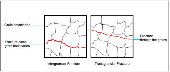
Figure 1.
Schematics of the difference between intergranular and transgranular fractures.
Since the raw material for AM is spherical powder particles, these can be produced using different atomization and spheroidization techniques. Today’s market-leading technology is gas atomization [11], which involves the fragmentation of a molten metal stream via a subsonic or supersonic jet of gas, forming metal droplets that are rapidly quenched and solidified. These powders are collected in a tank with an inert atmosphere. The finer fraction is separated to ensure a uniform size distribution. In view of this, such powders are usually highly spherical and optimal as raw materials for use in AM [12].
In this context, it should be noted that metal powders used in AM are often more costly than raw materials for conventional manufacturing processes. This cost difference arises due to the relatively niche nature of the AM market and its specific demands for alloy composition and particle size distributions. Established material suppliers have, however, started taking an interest in the metal AM industry, using the feedstock materials produced for the Metal Injection Molding (MIM) sector due to the similarities in the particle size needed for successful processing [13]. This approach can, in the future, result in cost reductions due to the established infrastructure of the MIM sector. However, when MIM feedstock is unavailable, it is reasonable to anticipate higher costs for raw materials.
In the present study, NiSi powders optimized for AM are targeted. A detailed thermodynamic evaluation of the effect that the presence of small quantities of either cobalt (Co), Ti, B, molybdenum (Mo), and/or vanadium (V) will have on the ductility and workability of NiSi powders will be performed, and optimized powder compositions will be produced through gas atomization. The following will be given special attention during the characterization of the produced powder particles: (i) the exact chemical composition and microstructure, (ii) the particle size distribution, and (iii) the melting behavior.
2. The Ni-Si System and Assessment of Optimum Properties
The binary phase diagram of the Ni-Si system describes the different phases and their stability regions as a function of composition and temperature; see Figure 2. This diagram exhibits a typical eutectic-type behavior with the formation of intermetallic compounds. The following phases are commonly observed in the Ni-Si system:
- Liquid phase—the liquid phase exists at high temperatures and compositions where the alloy is molten.
- Nickel silicide (Ni3Si)—this intermetallic compound forms at high temperatures and low Si concentrations.
- Nickel disilicide (NiSi2)—this phase forms at intermediate temperatures and moderate Si concentrations.
- Nickel monosilicide (NiSi)—this phase forms at lower temperatures and higher Si concentrations.
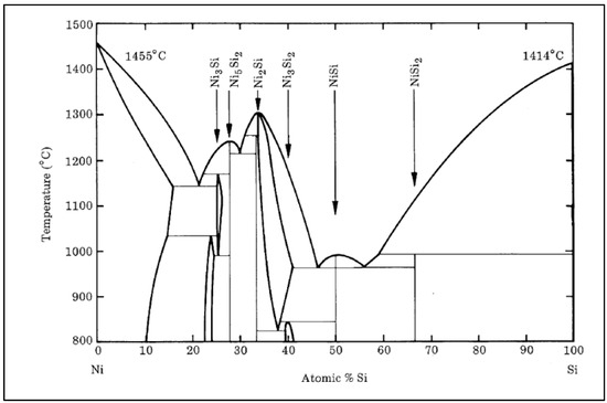
Figure 2.
The binary phase diagram of the Ni-Si system [14].
Figure 2.
The binary phase diagram of the Ni-Si system [14].
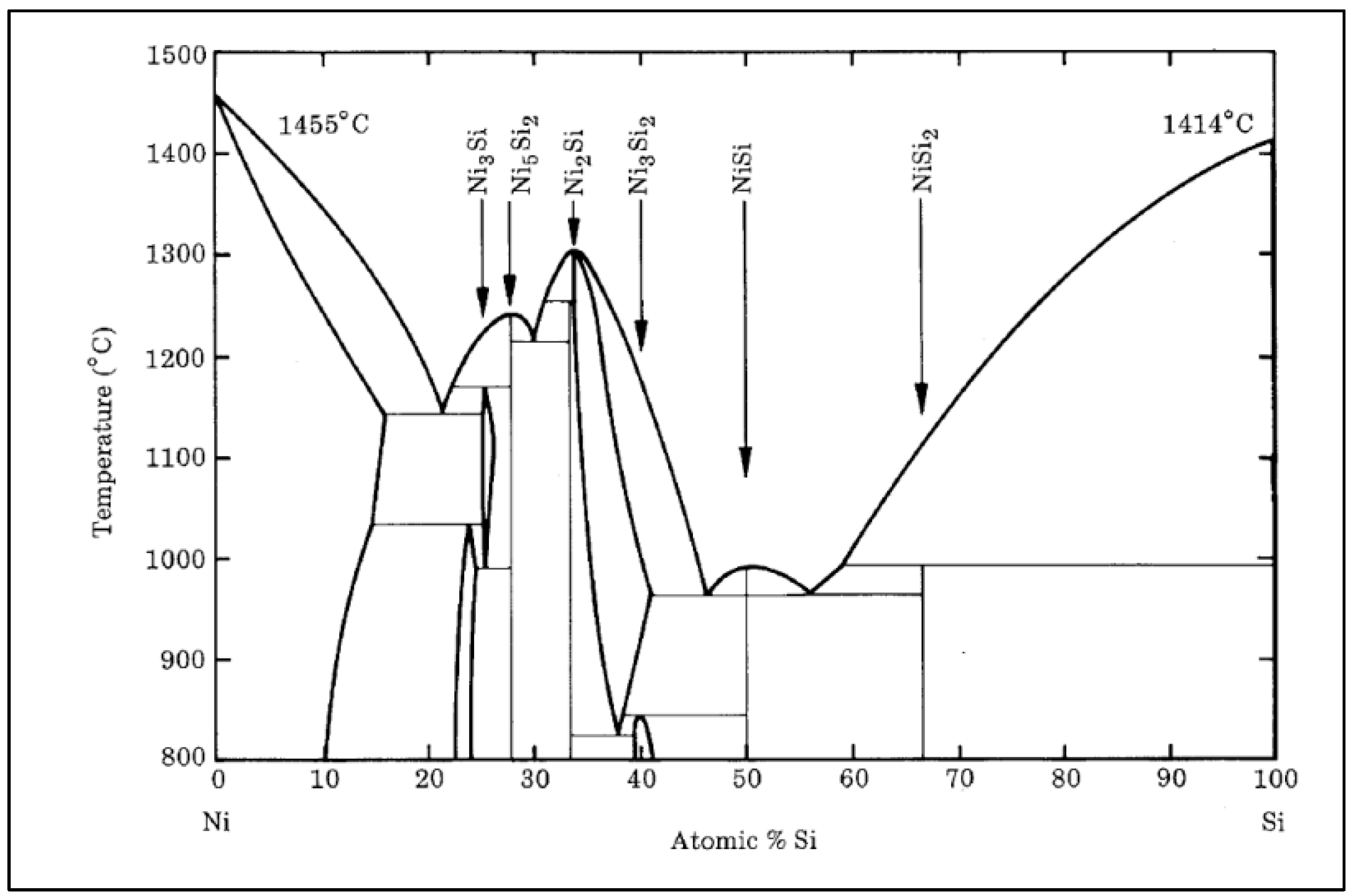
The Ni-Si system also provides information about the system’s solubility limits, phase boundaries, and various phase equilibria [14].
It is a well-known fact that Ni-based alloys tend to exhibit good ductility and toughness at room temperature. The addition of Si, however, has proven to affect the mechanical properties of the alloy through the formation of brittle intermetallic alloys [15]. It should be noted that the mechanical properties, including brittleness, can vary depending on the specific alloy composition, processing methods, and heat treatments employed. Additionally, the brittleness of a material can also be affected by factors such as grain size, impurities, and the presence of other alloying elements. Additions of elements such as Co [16], chromium (Cr) [17,18], V [19,20], Mo [21,22], Ti [8], B [10], and C [23] have been reported in the literature to have had positive effects on the fracture behavior of the Ni-Si system.
In the present study, the Thermo-Calc thermodynamic simulation software (Thermo-Calc AB, Solna, Sweden) using the TCNI12 database [24] was used to identify optimum NiSiX alloy compositions (X = Co, Ti, B, V, and/or Mo) by evaluating the solidification path and volumetric properties. The assessment was based on automated Scheil calculations of a vast range of potential alloy compositions, identifying candidates that transformed from fully liquid to fully solid over a low Solidification Temperature Range (STR), low change in density during solidification, and low hot cracking susceptibility (according to both Kou [25] and RDG [26] criteria).
Based on the selection criteria mentioned above, a handful of alloy compositions were selected that had (i) low STR, which implies a minimized build-up of internal stresses in the overall system and uniform solidification; (ii) low Kou index, indicating a smooth slope of the solidification curves at the end of solidification; (iii) low RDG index, indicating a low maximum strain rate during solidification; and (iv) a low change in density during solidification, indicating no sizeable volumetric change due to phase transformations which can lead to shrinkage, porosity, and cracking.
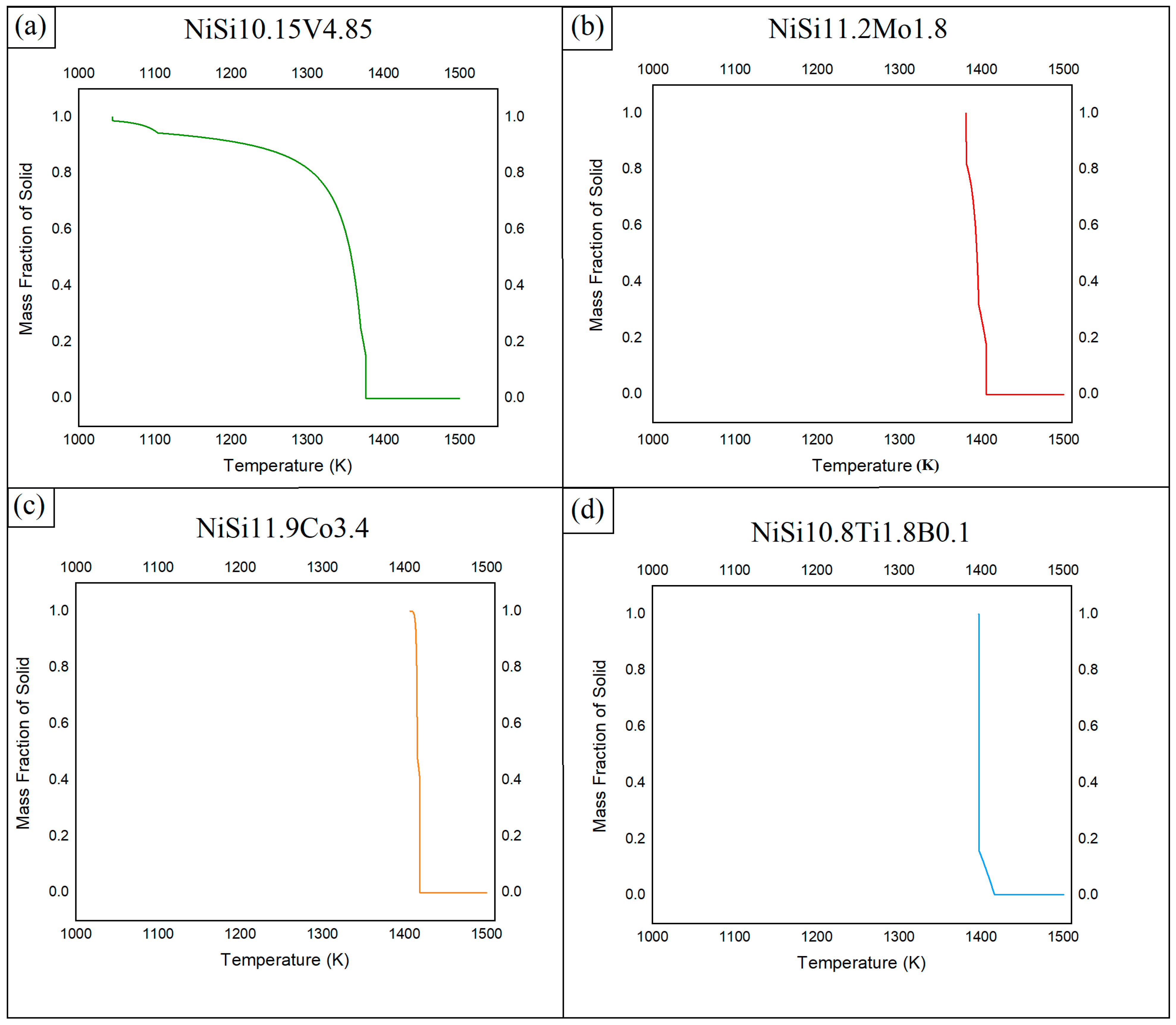
In Figure 3, the STR of the most promising alloys assessed is presented, i.e., (a) NiSi10.15V4.85 (NiSiV) wt%, (b) NiSi11.2Mo1.8 (NiSiMo) wt%, (c) NiSi11.9Co3.4 (NiSiCo) wt%, and (d) NiSi10.8Ti1.8B0.1 (NiSiTiB) wt%. As can be seen from the figure, the alloys with additions of Ti, B, Co, and/or Mo solidify rapidly, whereas the alloys with additions of V undergo 85–90% solidification in a similar rapid fashion, but the process continues for another 200 °C until it finally solidifies completely.
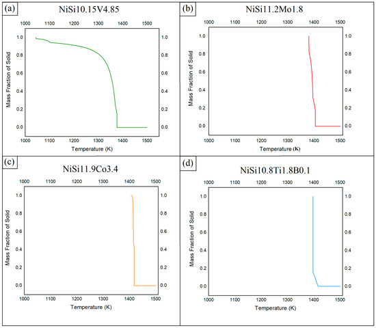
Figure 3.
STR of (a) NiSi10.15V4.85 (NiSiV) wt%, (b) NiSi11.2Mo1.8 (NiSiMo) wt%, (c) NiSi11.9Co3.4 (NiSiCo) wt%, and (d) NiSi10.8Ti1.8B0.1 (NiSiTiB) wt% assessed using the Thermo-Calc software.
To verify the outcome of the Thermo-Calc assessment, different alloy powders were produced through gas atomization.
3. Powder Production
The raw materials used in the present study for the production of the transition metal silicides, i.e., NiSiV, NiSiTiB, NiSiMo, and NiSiCo by wt%, were provided by Elkem Silicon AS (Norway), and the elements’ sources and purities are presented in Table 1.

Table 1.
Sources and purities of the elements used in producing the transition metal silicides NiSiV, NiSiTiB, NiSiMo, and NiSiCo.
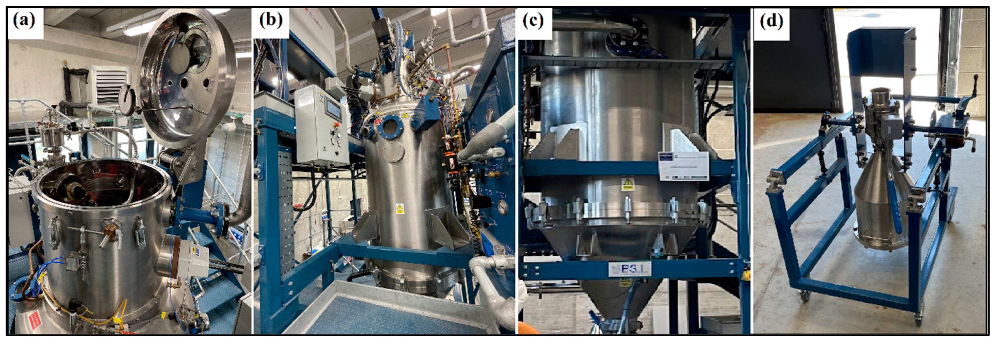
The elements were charged into a 75 kW induction furnace in the compositions identified to give optimum STR properties. Once molten, the melts were stirred with a graphite rod and with the induction currents to homogenize the melts before they were cast into 10 mm thick sheets. After being cooled to room temperature, the sheets were cut into smaller samples (35–50 mm) and sent off to the INSTM research unit (National Interuniversity Consortium of Materials Science and Technology) of the Polytechnic University of Turin (Italy), where the powder particles were produced in batches using a Hermiga 100/10 atomizer from Phoenix Scientific Industries Ltd. (PSI) (Hailsham, UK); see Figure 4.

Figure 4.
The gas atomizer (Hermiga 100/10 atomizer from PSI) used to produce the powder particles. (a) Melting chamber, (b) atomizing chamber view 1, (c) atomizing chamber view 2, and (d) powder collection unit.
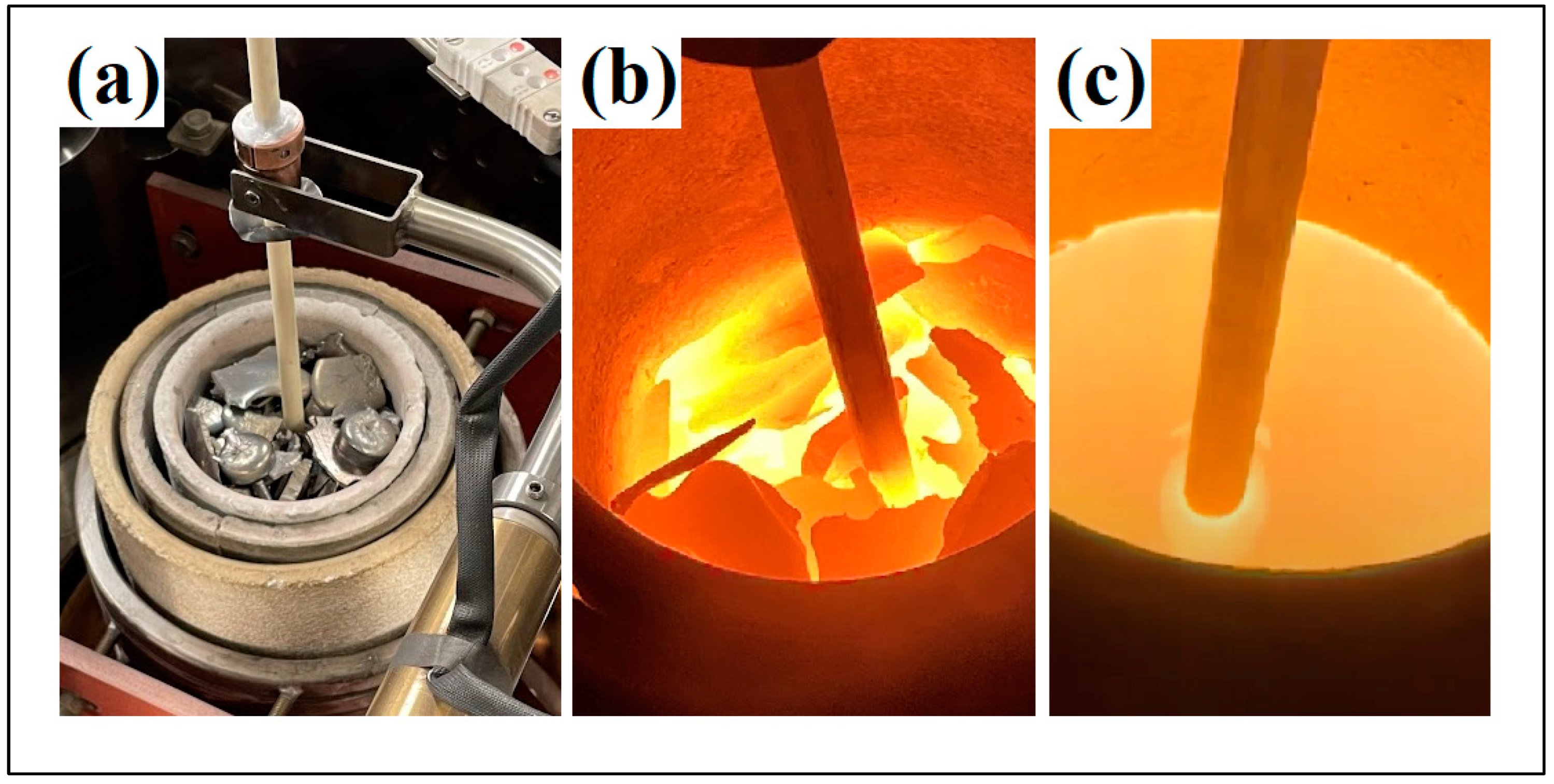
The amount of material loaded into the Al2O3 crucible of the atomizer varied between 5.4 to 7.2 kg as it depended on the size of the charge and the density of the alloy to be atomized. Each atomizing cycle started after the charge had melted and the atomizing chamber had been evacuated to 10−3 mbar. The heating step was performed in a vacuum to secure metal outgassing while both chambers were backfilled with Argon gas (Ar (g)) at 900 °C and with a slight overpressure of ~0.05 bar in the melting chamber. To ensure the complete melting of the base elements Ni and Si, the atomization temperature was manually adjusted to exceed the element’s respective liquidus temperatures. This step guaranteed that the entire charge underwent the molten state during the atomization process, and the die pressure was kept as constant as possible. The processing parameters for the individual alloys are given in Table 2, and the various melting stages are shown in Figure 5.
Table 2.
Process parameters and atomization yield for the produced transition metal silicides NiSiV, NiSiTiB, NiSiMo, and NiSiCo.

Figure 5.
The various melting stages of the produced transition metal silicide fragments in the Al2O3 crucible of the gas atomizer. (a) initial melting stage, (b) intermediate melting stage, (c) melted material.
The powder particles were produced in a size range of 20–63 μm, and the obtained yield in view of the individual alloys is given in Table 2. It should be noted that after the atomization step, some slag remained in the crucible, reducing the alloy’s overall yield. The slag was not analyzed but is believed to have affected the final composition of the NiSiTiB alloy. The Ti and B elements were meant to react with each other to form titanium boride (TiB2); however, since the temperature in the furnace was lower than the required temperature for the Ti and B reaction to take place (<1300 °C), there is a possibility that some of the Ti and B segregated into the slag phase.
4. Powder Characterization
Scanning Electron Microscopy (SEM) analyses were performed on all the produced powder particles using a Low-Voltage Field Emission Scanning Electron Microscope (LVFESEM) from Zeiss (Model: Supra 55VP, Oberkochen, Germany). The instrument was calibrated using a Pelcotec CDMS-1T traceable mount standard. Micrographic images were acquired using a secondary electron detector to provide information on the morphology of the atomized powders. The accelerating voltage was set to 10 keV and the working distance to 10 mm. Elemental analysis was performed using the attached Energy-Dispersive X-ray Spectroscopy (EDS) detector from EDAX (Pleasanton, CA, USA) at an increased accelerating voltage of 15 keV. It should be noted that SEM analysis is accepted throughout the AM industry as the main analytical instrument that provides a general overview of the powder particles in view of size, shape, and surface roughness.
An X-ray Diffraction (XRD) unit from Bruker (D8 Focus X-ray diffractometer, Billerica, MA, USA), equipped with a copper X-ray cathode tube with a wavelength of 1.54 Å operated at 40 kV and 44 mA, was used to retrieve the diffractogram of the produced powder particles. The unit was calibrated by measuring a standard reference material (NIST-SRM-660a LaB6 powder)(Merck-Life Science, Darmstadt, Germany), and the 2θ values obtained from the XRD pattern were compared to the issued certificate values. The beam was aligned following the placement of the samples on the diffractometer stage. A scan range of 10–90° was selected with a step size of 0.1°. The Bruker AXS DIFFRAC.SUITE software package EVA was adopted to perform spectral analysis and phase identifications.
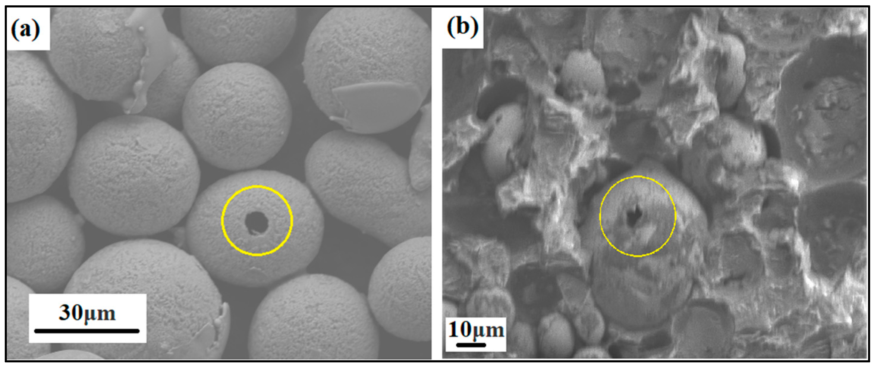
Even the porosity of the produced powder particles was analyzed in SEM by mounting the powders in ClaroCit, which is an acrylic resin (see Figure 6). Once cured, the samples were ground in Saphir 330 from ATM (Germany) using Struers silicon carbide (SiC) paper with 320 grit and 46 μm grain size.
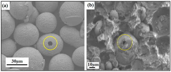
Figure 6.
SEM image of ground and heat-treated powder particles showing particle porosity, i.e., (a) NiSiCo powder particles at the 30 μm scale and (b) NiSiMo powder particles at the 10 μm scale, mounted in acrylic resin.
The Particle Size Distribution (PSD) analyses were carried out using a Partica LA-960 unit from Horiba (Kyoto, Japan) in deionized water, which uses laser diffraction to measure the size distributions. The wet analysis method (Lower Duwamish Waterway (LD-W)) was used in which particles are dispersed in a liquid. All samples were thoroughly mixed by rotating the sample container top-over-bottom ten times before withdrawing the powder specimen required for the analysis. The particle distributions were recorded in terms of the volume distribution against the particle size, assuming all particles were spherical.
A Differential Scanning Calorimetric (DSC) unit equipped with a Thermal Gravimetric Analyzer (TGA) from NETZSCH, model DSC STA 449 F3 Jupiter (Germany), was used to analyze the phase transformation of the various compositions at elevated temperatures. The system allows for a vacuum-tight setup to allow the analysis to be performed under a vacuum or in an inert, oxidizing, or reducing atmosphere. The analyses were performed using an Al2O3 crucible equipped with a lid. The heating rate was 10 °C/min up to a temperature of 900 °C before being lowered to 2 °C/min to better acquire any phase transformations in the desired region.
5. Results and Discussion
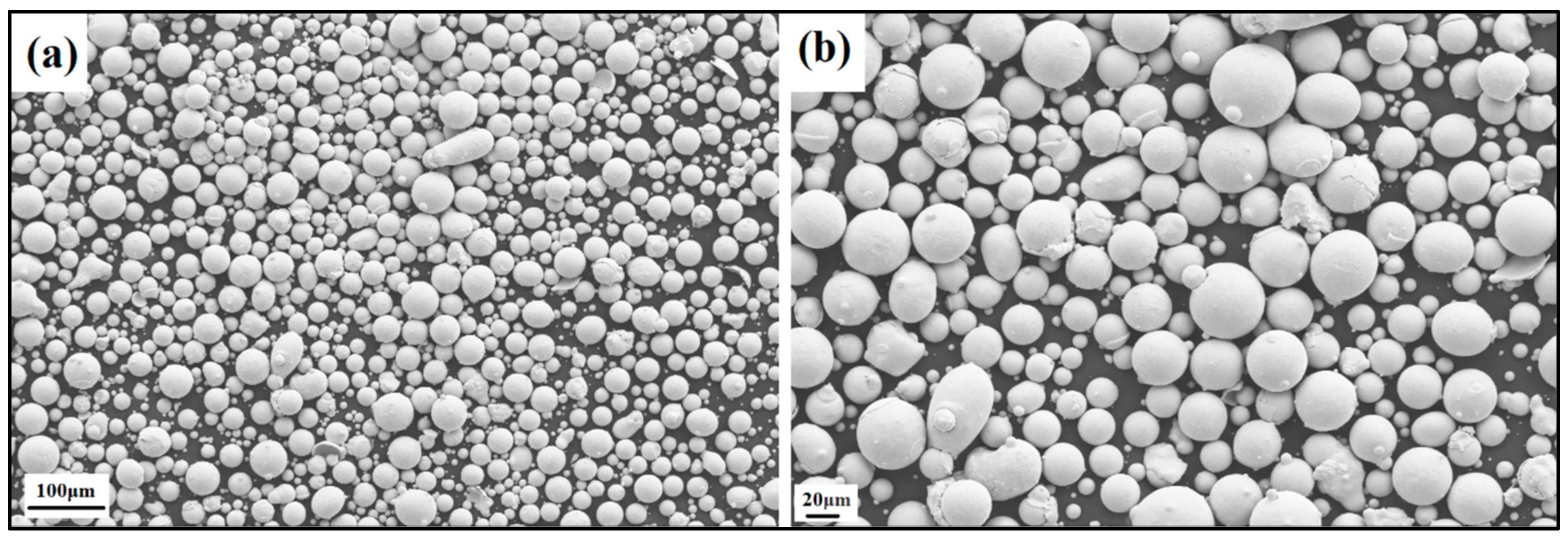
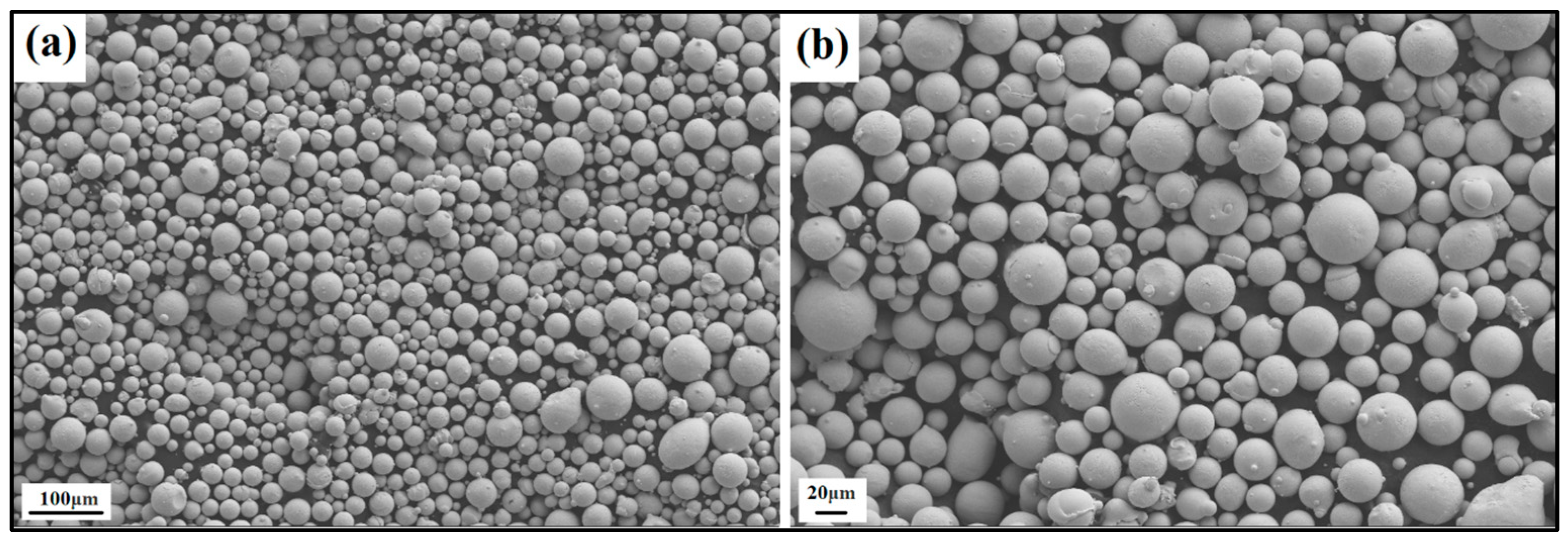
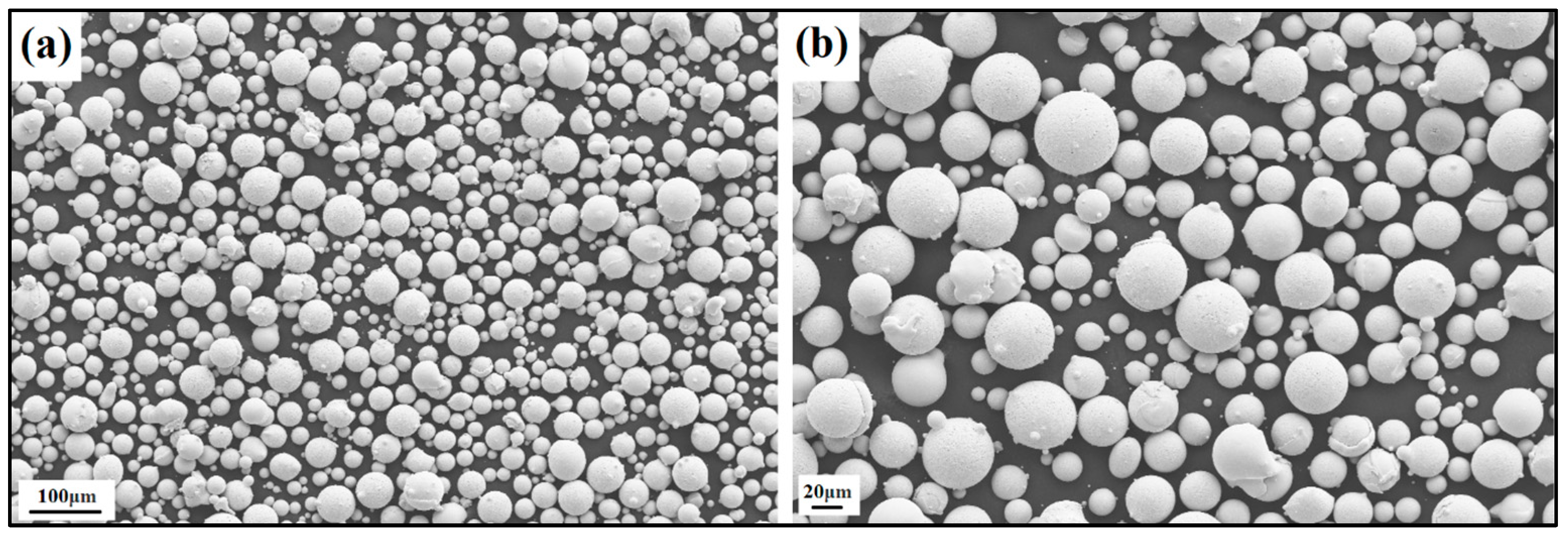
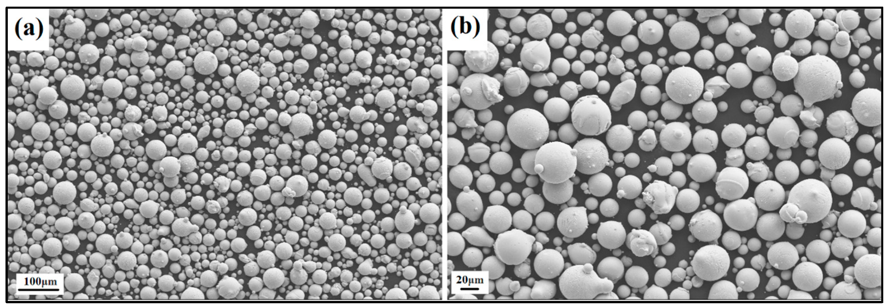
The produced powder particles, i.e., NiSiCo, NiSiMo, NiSiTiB, and NiSiV, were examined using SEM, and the secured micrographic images are presented in Figure 7, Figure 8, Figure 9 and Figure 10. During the SEM analysis, it was observed that a few satellite particles were present in all powders. However, the number of satellites was more pronounced in the case of the NiSiTiB and NiSiV powder particles (see Figure 9 and Figure 10), which can be attributed to the high atomizing pressure utilized during the production of these particles. The increased atomizing pressure is believed to have led to a turbulent flow within the atomization chamber, causing the collision of newly formed semi-solidified droplets with larger powder particles, resulting in the formation of satellite particles.
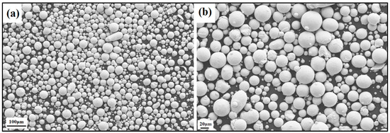
Figure 7.
SEM image of the NiSiCo (NiSi11.9Co3.4 wt%) powder particles at the (a) 100 μm scale and (b) 20 μm scale.
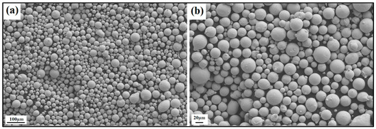
Figure 8.
SEM image of the NiSiMo (NiSi11.2Mo1.8 wt%) powder particles at the (a) 100 μm scale and (b) 20 μm scale.
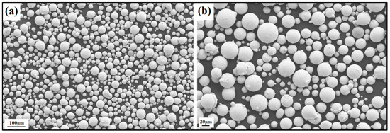
Figure 9.
SEM image of the NiSiTiB (NiSi10.78Ti1.84B0.1 wt%) powder particles at the (a) 100 μm scale and (b) 20 μm scale.
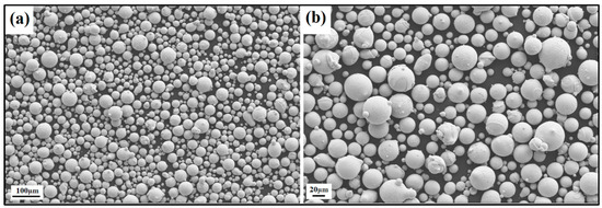
Figure 10.
SEM image of the NiSiV (NiSi10.15V4.85 wt%) powder particles at the (a) 100 μm scale and (b) 20 μm scale.
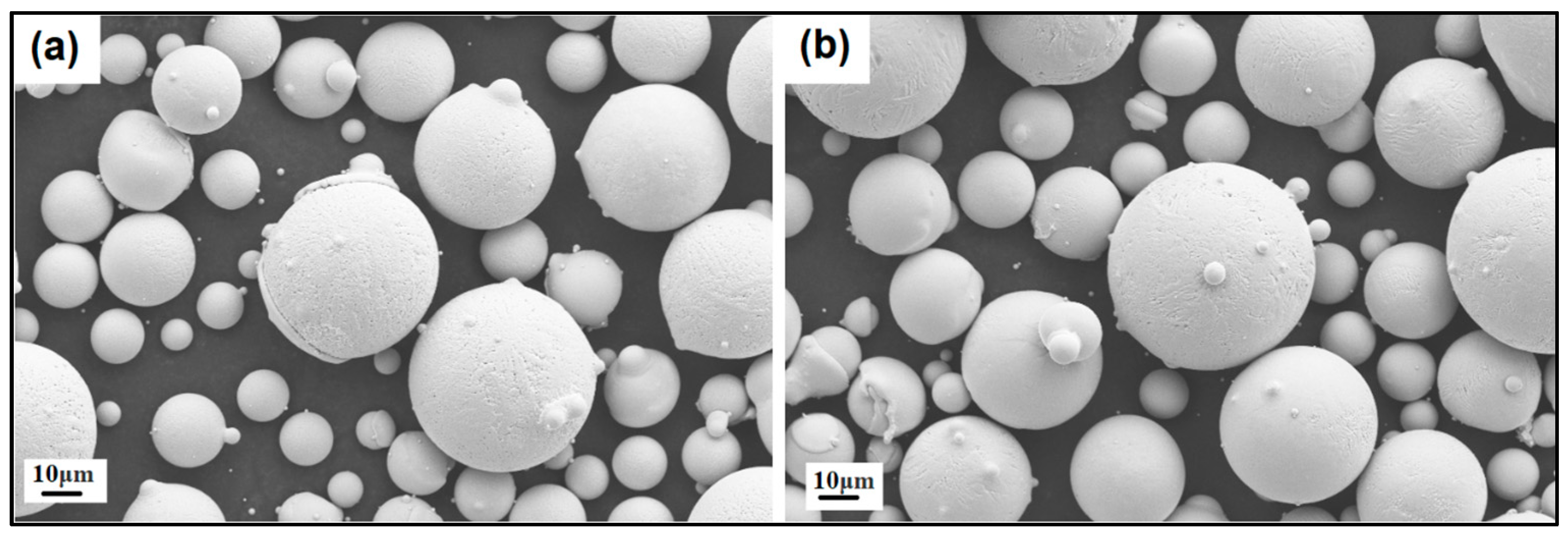
It should be noted that both the NiSiTiB and NiSiV powder particles also exhibited higher surface roughness compared to the other powder particles produced; see Figure 11. Increased surface roughness can have detrimental effects on the performance of powder particles, especially when employed in AM applications. Rough surfaces are known to affect the flowability of powder by enhancing the interparticle friction [27]. In other words, to secure improved flowability, it is desirable to produce highly spherical and smooth particles [28,29].
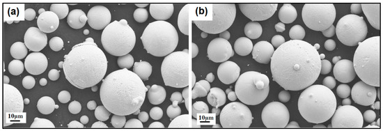
Figure 11.
SEM images of the (a) NiSiTiB and (b) NiSiV powder particles, showing the surface roughness of the particles at the 10 μm scale.
Enhancing the surface roughness and minimizing the formation of satellite particles are vital and achievable through the fine-tuning of atomization parameters and powder processing techniques [30]. Such improvements will ultimately enhance the powder particle’s suitability for AM applications. The surface roughness of the powder particles affects the powder packing density, the flowability during spreading, the inter-particle bonding, and the ultimate surface finish of the built parts [31]. Effective powder sieving and classification post-atomization can mitigate the presence of fine and irregular particles, leading to smoother powder surfaces and ultimately enhancing the packing and flowability of powders during printing. The microstructure of these powder particles is characterized by a predominantly equiaxed structure, interspersed with regions featuring dendritic grain morphology. The occurrence of dendritic grain structures is a common feature in gas-atomized powders due to the rapid solidification process they undergo. Interestingly, as the particle size decreases, there is a noticeable reduction in the size of these dendritic grains [32].
EDS analyses were used to evaluate the distribution of the added elements in each of the produced powders. The technique successfully detected the concentration of the base elements Ni and Si and the lower concentrations of Co, Ti, B, Mo, V, and C; see Table 3. It should be noted that while EDS provides qualitative elemental analysis, the analytical technique also allows for semi-quantitative information to be derived for estimation purposes [33]. Based on this, the EDS analysis also revealed that the concentrations of the additional elements were higher than the initial amounts. This discrepancy is believed to be attributed to the fact that the elements segregated to the grain boundaries and became unevenly distributed within the molten alloy [34]. As a result, certain material regions exhibited a higher concentration of these elements than others. Notably, boron, due to its lower proportion relative to the other elements, was identified through the utilization of the element-locking module within the TEAM: Texture and Elemental Analysis Microscopy software (version 4.5).
Table 3.
Quantitative EDS results of the produced NiSiCo, NiSiMo, NiSiTiB, and NiSiV powder particles.
As can be seen from Table 3, the obtained EDS results confirmed the presence of a high concentration of Ni in the range of 77–83 wt%, which agrees well with the expectations. Additionally, the Si concentration was established to be in the range of 10–15 wt%, and for the different alloying elements, in the range of 1–6 wt%. Given the low concentration of the alloying elements, it was decided to perform complementary analyses and combine the result with possible reactions supported by the Ni-Si binary phase diagram to confirm the EDS results [35].
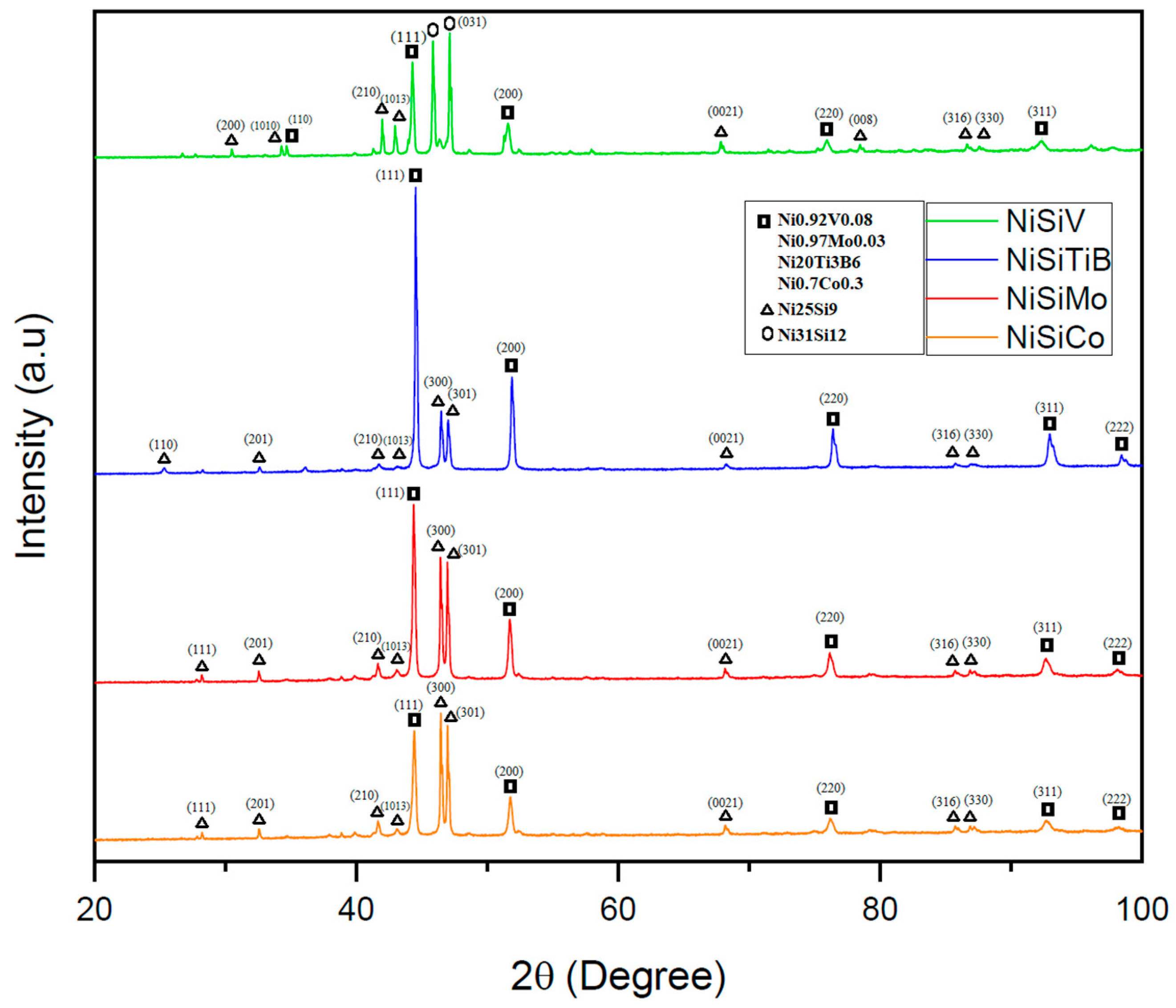
The performed XRD analyses revealed that the additional elements in each of the produced powders were detected in conjunction with the Ni; see Figure 12. It was also established that the produced samples exhibited similar crystal structures as the α-Ni phase, as well as the intermetallic Ni3Si phase (with lattice parameters of a0 = 3.519 and 3.506, respectively) [36]. Even the presence of the metastable Ni25Si9 phase was established, which is believed to have been formed due to rapid solidification/quenching. This is in line with what other researchers have indicated in the literature, i.e., that the formation of the metastable Ni25Si9 phase may occur during rapid quenching of the NiSi [37,38]. In other words, the alloying elements have, in this case, acted as grain refiners, resulting in a more complex microstructure.
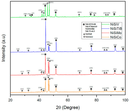
Figure 12.
XRD scans of the NiSi-based powders with additions of Co, Ti, B, V, and Mo. The scan of the powder particles represented by the orange line is for the composition NiSiCo, the red line for NiSiMo, the blue line for NiSiTiB, and the green line for NiSiV.
To further validate the hypothesis regarding the presence of the metastable phase Ni25Si9, the NiSiCo powder particles were subjected to heat treatment by raising their temperature to 600 °C and subsequently cooling. The XRD results of these particles—see Figure 13—clearly demonstrated the disappearance of the metastable phase, leaving only the Ni3Si phase present in the powders at room temperature. These findings confirmed the complex microstructure development in each of the systems investigated, as well as the presence of the metastable Ni25Si9 phase. In view of this, understanding these alloys’ phase transformations and behavior during heat treatment is crucial for optimizing their properties and, thereby, their performance in various applications.
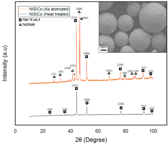
Figure 13.
XRD scan of the heat-treated (black) and atomized (red) NiSiCo powder particles shows the total decay of the Ni25Si9 metastable phase, as well as the surface morphology of the particles after heat treatment.
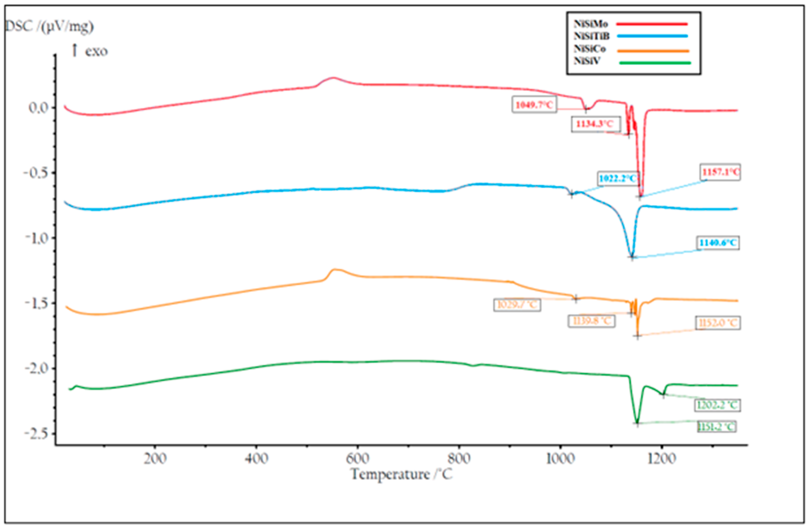
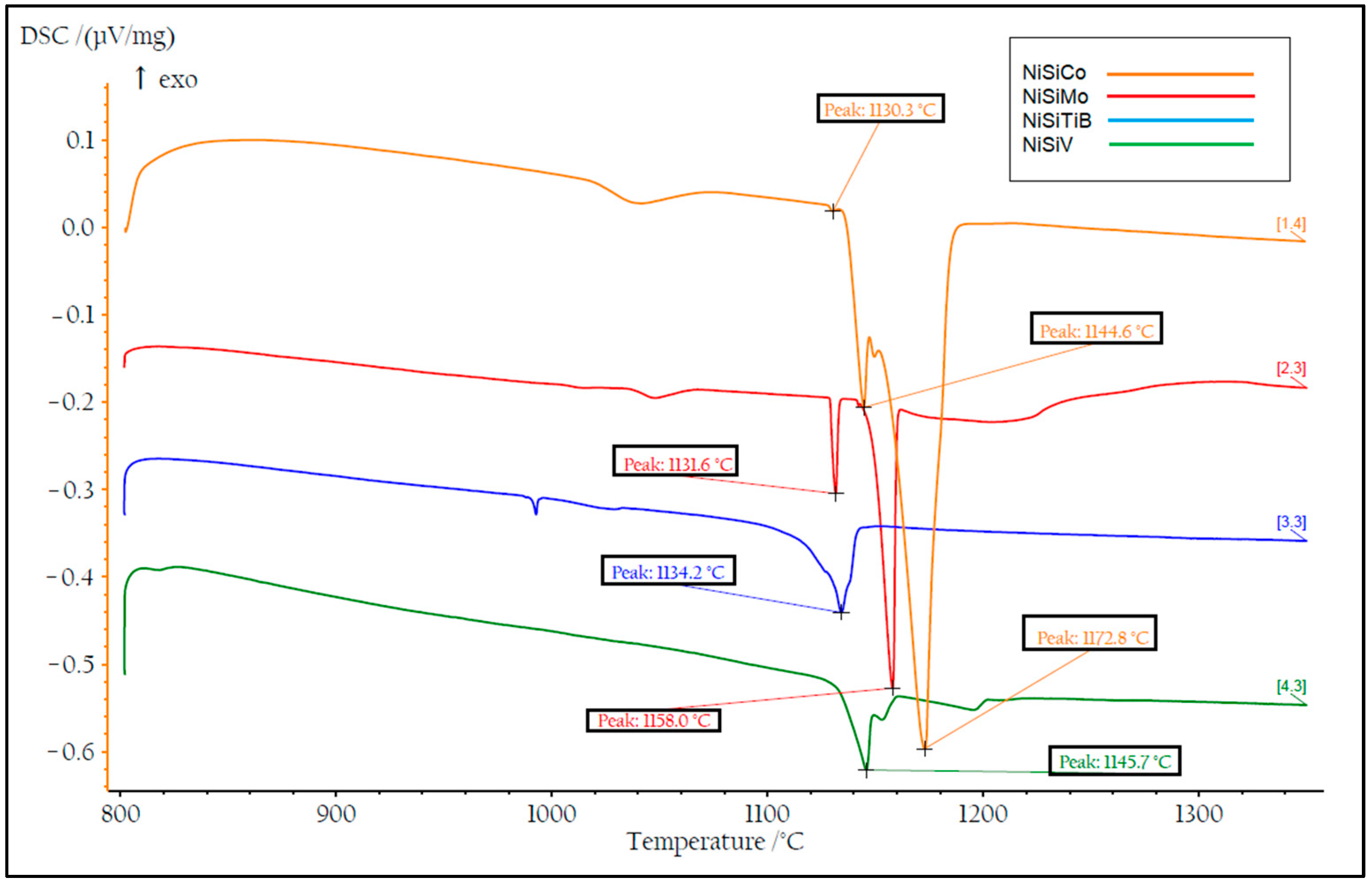
DSC measurements were also performed on all the produced powders. Two heating cycles were utilized with a maximum temperature of 1400 °C to ensure that the measurements were performed on homogeneous samples; see Figure 14 and Figure 15. During the first heating cycle, the samples were heated at 10.2 °C/min, revealing an exothermic peak around 500 °C, which confirmed the presence of the Ni25Si9 phase. However, during the second heating cycle performed at 1.8 °C/min, this peak was no longer visible, which further supports the hypothesis regarding the presence of a metastable phase that completely decays after material homogenization.
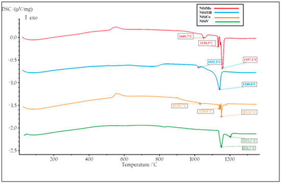
Figure 14.
The first temperature cycle of the DSC measurements of the produced NiSibased powders. The result of the powder particles represented by the orange line is for composition NiSiCo, the red line for NiSiMo, the blue line for NiSiTiB, and the green line for NiSiV.
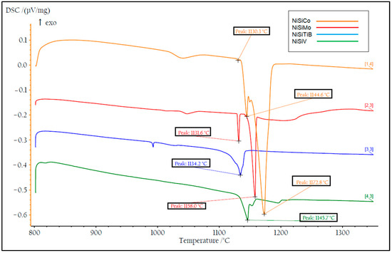
Figure 15.
The second temperature cycle of the DSC measurements of the produced NiSi-based powders. The result of the powder particles represented by the orange line is for composition NiSiCo, the red line for NiSiMo, the blue line for NiSiTiB, and the green line for NiSiV.
From Figure 14, it can also be seen that the first endothermic peak observed for all the powders in the temperature range 1030–1050 °C can be attributed to the β1-Ni3Si to β2-Ni3Si polymorph transformation within the Ni3Si phase, i.e., the transformation from the low-temperature β1-Ni3Si phase to the more ordered high-temperature β2-Ni3Si phase. It can further be seen that, as the temperature increases to 1130 °C, a second endothermic peak appears, corresponding to the polymorph transformation from β2-Ni3Si to β3-Ni3Si, accompanied by the formation of the disordered Ni3Si phase. The third endothermic peak, observed around 1140–1157 °C, is believed to be the eutectic reaction where Ni and Ni3Si entirely melt.
During the subsequent heating cycle shown in Figure 15, it can also be seen that the β1-Ni3Si to β2-Ni3Si transition peak was absent. This is believed to be a result of the precipitation of Ni during the transformations from the β1-Ni3Si phase to the β2-Ni3Si phase and further from the β2-Ni3Si phase to the β3-Ni3Si phase. An accumulation of Si was also established to have occurred, which is believed to be a result of the low solubility of Si in the α-Ni phase [39]. Consequently, in the present cases, rapid solidification led to the formation of the metastable phase Ni25Si9 rich in Si. It is, however, essential to note that the individual chemistries of the different powder particles produced may vary from the bulk chemistry, as certain elements may precipitate early and accumulate in specific regions.
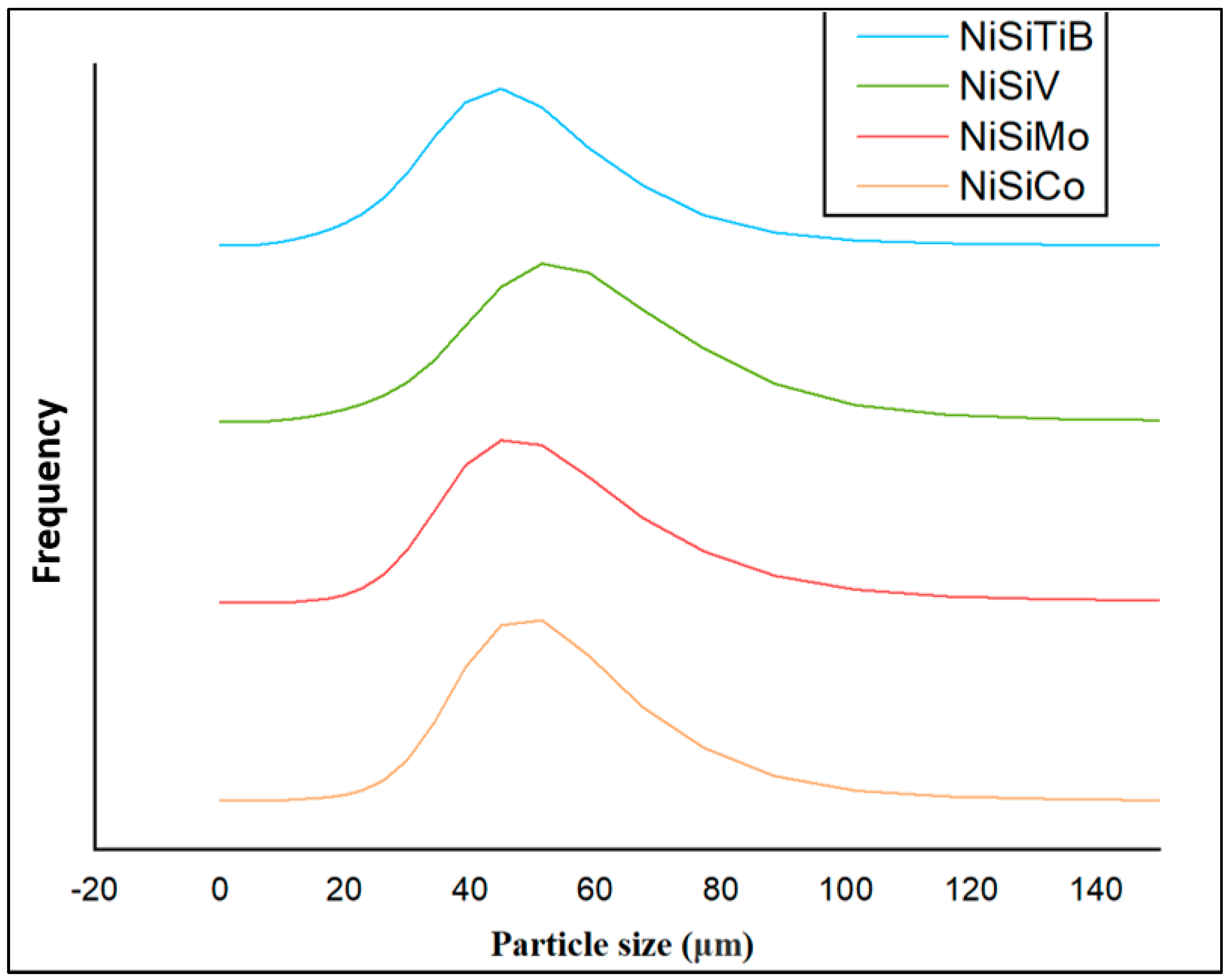
When comparing the obtained particle size distributions for the different powder particles presented in Figure 16, the peak for NiSiTiB shifts slightly to the left, indicating a minor increase in particle size within the 20–60 μm range. This shift is believed to be attributed to the higher gas atomization pressure used while producing these powder particles, as an increase in the gas atomization pressure tends to decrease the powder’s overall particle size. However, in the case of NiSiV, the higher gas atomization pressure resulted in an increased satellite formation, as previously mentioned; see Figure 9.
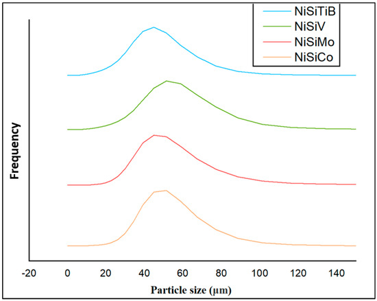
Figure 16.
The particle size distribution of the produced NiSi-based powders. The result of the powder particles represented by the orange line is for composition NiSiCo, the red line for NiSiMo, the blue line for NiSiTiB, and the green line for NiSiV.
The reduced particle size in the case of the NiSiTiB powder particles can have both advantages and disadvantages. On the one hand, it can lead to higher densification and packing efficiency during AM. The reduced size can also mean increased particle surface energy, which during AM can lead to agglomeration and, in the case of Laser Powder Bed Fusion (L-PBF), the higher reflectivity of the laser [17]. The diameter of the powder particles can significantly influence the quality of the built parts. Smaller particles allow for finer layer resolutions, resulting in smoother surface finishes, while larger particles might produce rougher finishes. However, an extreme reduction in particle size can result in porosity due to inadequate fusion. A proper sieving technique can help control the particle diameter, and adjusting AM parameters, such as the gas atomizing pressure, can optimize the powder’s particle size distribution [31].
6. Conclusions
In the present study, NiSiCo, NiSiV, NiSiMo, and NiSiTiB powders have been produced through gas atomization and properties related to the powder’s ductility and workability characterized by SEM, EDS, XRD, DSC, and PSD. The chemical composition, morphology, and microstructural evolution of the produced powders were systematically analyzed. The main conclusions are listed below:
- The presence of small additions of transition metals such as Co, Ti, B, V, and/or Mo could ensure a change in the fracture mode of the NiSi-printed parts from intergranular to transgranular.
- The change in fracture mode will improve the ductility and strength of the produced parts as the added transition metals are segregated to the grain boundaries, thereby restricting the crack propagation within the powders. A similar role is expected from the produced powders in printed parts.
- A variation in relative strength was identified between the produced powder particles as a result of the variation in Si concentration, i.e., NiSiCo (NiSi11.9Co3.4 wt%), NiSiV (NiSi10.15V4.85 wt%), NiSiMo (NiSi11.2Mo1.8 wt%), and NiSiTiB (NiSi10.78Ti1.84B0.1 wt%), and thereby the presence of different phases.
- Porosity was established to exist in some of the produced powder particles with higher surface roughness and an increased number of satellites that may hinder optimum flow conditions during printing, e.g., in the case of NiSiTiB and NiSiV powder particles.
- The gas atomization pressure can be increased to a certain limit (dependent on reactor size and type) to obtain a smaller powder particle size suitable for L-PBF, after which, the satellite formation dominates the powder production method and reduces powder quality.
- Stable printing parts are expected when using the presently produced powder particles once printing parameters are adjusted according to the optimum conditions in each specific case.
The present study’s findings can guide further optimization of the production process for powders to minimize porosity and ensure a more uniform distribution of the added transition metals.
7. Future Work
Further work is required to confirm the present findings in view of optimum properties for AM by giving special attention to the powders’:
- Flow behavior (evaluated using an FT4 Rheometer).
- Printability (evaluated using Direct Energy Deposition (DED) and Laser Powder Bed Fusion (L-PBF)).
- Chemical and structural analysis (X-ray Photoelectron Spectroscopy (XPS) analyses to evaluate the amount of oxygen (O) adsorbed on the surfaces of the powder particles during transport and environmental exposure).
The printing parameters will also be adjusted and optimized in view of the most favorable conditions of the different powders.
Author Contributions
Conceptualization, M.I. and R.E.A.; Methodology, M.I., G.G. and R.E.A.; Software, Q.D. and E.W.H.; Validation, C.H.; Investigation, M.I. and Q.D.; Data curation, E.W.H.; Writing—original draft, M.I.; Writing—review & editing, E.W.H., C.H. and R.E.A.; Supervision, C.H. and R.E.A.; Funding acquisition, G.G. All authors have read and agreed to the published version of the manuscript.
Funding
This research was funded by Norwegian Research Council (NFR) grant number 309856.
Data Availability Statement
Not applicable.
Acknowledgments
The authors wish to express their gratitude to the Norwegian Research Council (NFR) for the funding received through the project Development and Production of Metal Alloys for Powder-Based Additive Manufacturing (MADAM), Ref. no. 309856. The supervision and training received from Actis Grande Marco and Associate Gobber Federico Simone from Polytechnic di Torino, Italy, during the production of the powders, is highly acknowledged, as well as the efforts to ensure equipment availability by Future Materials AS and Elkem ASA, Norway. The authors also wish to acknowledge the constant support provided by Sergey Khromov and Elvia Anabela Chavez Panduro at the Norwegian University of Science and Technology (NTNU) in the analysis domain.
Conflicts of Interest
The authors declare no conflict of interest.
References
- Örnek, C. Additive Manufacturing–A General Corrosion Perspective. Corros. Eng. Sci. Technol. 2018, 53, 531–535. [Google Scholar] [CrossRef]
- Gorsse, S.; Hutchinson, C.; Gouné, M.; Banerjee, R. Additive manufacturing of metals: A brief review of the characteristic microstructures and properties of steels, Ti-6Al-4V and high-entropy alloys. Sci. Technol. Adv. Mater. 2017, 18, 584–610. [Google Scholar] [CrossRef] [PubMed]
- Ibrahim, M.; Sætre, T.O.; Aune, R.E. Laser metal deposition of nickel silicide on S355 structural steel. In Proceedings of the TMS 2022 151st Annual Meeting & Exhibition Supplemental Proceedings, Anaheim, CA, USA, 27 February–3 March 2022; pp. 249–258. [Google Scholar]
- Easton, M.A.; St. John, D.H. Improved Prediction of the Grain Size of Aluminum Alloys that Includes the Effect of Cooling Rate. Mater. Sci. Eng. A 2008, 486, 8–13. [Google Scholar] [CrossRef]
- Totten, G.; Bates, C.; Clinton, N. Residual Stress, Distortion and Cracking. Handb. Quenchants Quenching Technol. 2001, 441–492. [Google Scholar]
- Jang, J.S.; Ou, C.; Cheng, C. The Evolution of Microstructure Change and Mechanical Properties for a Nickel Silicide based Alloy Poped with Carbon and Boron. Mater. Sci. Eng. A 2002, 329, 455–460. [Google Scholar] [CrossRef]
- Xiao, W.; Zhao, Y.; Yang, T. Cubic Ordered Intermetallic Alloys, in Advanced Multicomponent Alloys: From Fundamentals to Applications; Springer: Berlin/Heidelberg, Germany, 2022; pp. 91–103. [Google Scholar]
- Takasugi, T.; Nagashima, M.; Izumi, O. Strengthening and Ductilization of Ni3Si by the Addition of Ti Elements. Acta Metall. Mater. 1990, 38, 747–755. [Google Scholar] [CrossRef]
- Zhang, X.; Niu, M.; Wu, C.; Chen, J. The Effect of Titanium Addition on the Microstructure, Mechanical and Tribological Properties of Ni3Si Alloys Prepared by Powder Metallurgy Method. Mater. Und Werkst. 2019, 50, 1537–1544. [Google Scholar] [CrossRef]
- Taub, A.; Briant, C. Improved Ductility of Ni3Si by Microalloying with Boron or Carbon. Metall. Trans. A 1989, 20, 2025–2032. [Google Scholar] [CrossRef]
- Gibson, I.; Rosen, D.; Stucker, B.; Khorasani, M.; Gibson, I.; Rosen, D.; Stucker, B.; Khorasani, M. Materials for Additive Manufacturing. Addit. Manuf. Technol. 2021, 379–428. [Google Scholar]
- Ünal, A. Effect of Processing Variables on Particle Size in Gas Atomization of Rapidly Solidified Aluminium Powders. Mater. Sci. Technol. 1987, 3, 1029–1039. [Google Scholar] [CrossRef]
- Choong, Y.H.; Krishnan, M.; Gupta, M. A Printability Evaluation of Fine and Coarse Powder in Binder Jetting of Dense and Porous Copper Parts. Prog. Addit. Manuf. 2022, 1–23. [Google Scholar] [CrossRef]
- Nash, P. Phase Diagrams of Binary Nickel Alloys; ASM International Detroit: Detroit, MI, USA, 1991. [Google Scholar]
- Weisert, E. High Alloys to Combat Corrosion. Corrosion Engineering. Sci. Technol. 1957, 13, 61–73. [Google Scholar]
- Liu, Y.; Wang, H. Toughening and Dry Sliding Wear Resistance of Co3Mo2Si Alloys. Wear 2013, 297, 952–957. [Google Scholar] [CrossRef]
- Takasugi, T.; Kawai, H.; Kaneno, Y. The Effect of Cr Adition on Mechanical and Chemical Properties of Ni3Si Alloys. Mater. Sci. Eng. A 2002, 329, 446–454. [Google Scholar] [CrossRef]
- Sun, A.; Chen, Y.; Wang, X.; Han, Q. Ultrafast laser induced NiCrBSi coatings. In IOP Conference Series: Materials Science and Engineering; IOP Publishing: Bristol, UK, 2019; p. 12145. [Google Scholar]
- Guo, Y.; Jia, L.; Kong, B.; Zhang, H.; Zhang, H. Simultaneous Improvement in Fracture Toughness and Oxidation Resistance of Nb-Si based Alloys by Vanadium Addition. Mater. Sci. Eng. A 2017, 701, 149–157. [Google Scholar] [CrossRef]
- Zou, J.; Cheng, J.; Feng, G.; Xie, J.; Yu, F.J.M. Effect of V Addition on Microstructure and Properties of Cu-1.6 Ni-1.2 Co-0.65 Si Alloys. Metals 2019, 9, 679. [Google Scholar] [CrossRef]
- Li, Y.; Lin, X.; Hu, Y.; Yu, J.; Dong, H.; Liu, F.; Huang, W. The Effect of Mo on Microstructure and Mechanical Properties of Nb-22Ti-16Si Alloy Additively Manufactured via Laser Directed Energy Deposition. J. Alloys Compd. 2021, 858, 158143. [Google Scholar] [CrossRef]
- Zhang, P.; Li, M.; Yan, H.; Chen, J.; Yu, Z.; Ye, X. Microstructure Evolution of Ni-Mo-Fe-Si Quaternary Metal Silicide Alloy Composite Coatings by Laser Cladding on Pure Ni. J. Alloys Compd. 2019, 785, 984–1000. [Google Scholar] [CrossRef]
- Takasugi, T.; Yoshida, M. Mechanical Properties of the Ni 3 (Si, Ti) Alloys Doped with Carbon and Beryllium. J. Mater. Sci. 1991, 26, 3032–3040. [Google Scholar] [CrossRef]
- ThermoCalc. Nickel Based Superalloys Databases. Available online: https://thermocalc.com/products/databases/nickel-based-alloys/ (accessed on 20 May 2022).
- Kou, S. A Criterion for Cracking During Solidification. Acta Mater. 2015, 88, 366–374. [Google Scholar] [CrossRef]
- Rappaz, M.; Drezet, J.-M.; Gremaud, M. A New Hot-Tearing Criterion. Metall. Mater. Trans. A 1999, 30, 449–455. [Google Scholar] [CrossRef]
- Brandl, E.; Heckenberger, U.; Holzinger, V.; Buchbinder, D. Additive Manufactured AlSi10Mg Samples using Selective Laser Melting (SLM): Microstructure, High cycle Fatigue, and Fracture Behavior. Mater. Des. 2012, 34, 159–169. [Google Scholar] [CrossRef]
- Olakanmi, E.O.; Cochrane, R.F.; Dalgarno, K.W. A Review on Selective Laser Sintering/melting (SLS/SLM) of Aluminium Alloy Powders: Processing, Microstructure, and Properties. Prog. Mater. Sci. 2015, 74, 401–477. [Google Scholar] [CrossRef]
- Anderson, I.E.; White, E.M.; Dehoff, R. Feedstock Powder Processing Research Needs for Additive Manufacturing Development. Curr. Opin. Solid State Mater. Sci. Eng. A 2018, 22, 8–15. [Google Scholar] [CrossRef]
- Mussatto, A.; Groarke, R.; O’Neill, A.; Obeidi, M.A.; Delaure, Y.; Brabazon, D. Influences of Powder Morphology and Spreading Parameters on the Powder Bed Topography Uniformity in Powder Bed Fusion Metal Additive Manufacturing. Addit. Manuf. Technol. 2021, 38, 101807. [Google Scholar] [CrossRef]
- Hebert, R.J. Metallurgical Aspects of Powder Bed Metal Additive Manufacturing. J. Mater. Sci. 2016, 51, 1165–1175. [Google Scholar] [CrossRef]
- Sakaguchi, Y.; Harada, T.; Kuji, T. Microstructural Studies of Nd Fe B Powders Produced by Gas Atomization. Mater. Sci. Eng. A 1994, 181, 1232–1236. [Google Scholar] [CrossRef]
- Nasrazadani, S.; Hassani, S. Modern Analytical Techniques in Failure Analysis of Aerospace, Chemical, and Oil and Gas Industries. In Handbook of Materials Failure Analysis with Case Studies from the Oil and Gas Industry; Butterworth-Heinemann: Oxford UK, 2016. [Google Scholar]
- Hausner, H.H. (Ed.) Friction conditions in a mass of metal powder. In Secondary Friction Conditions in a Mass of Metal Powder; APMI International: Princeton, NJ, USA, 1967; pp. 7–13. [Google Scholar]
- Chen, G.; Tan, P.; Zhao, S.Y.; He, W.W.; Tang, H. Spherical Ti-6Al-4V Powders Produced by Gas Atomization. Key Eng. Mater. 2016, 704, 287–292. [Google Scholar] [CrossRef]
- Pigozzi, G.; Mukherji, D.; Gilles, R.; Barbier, B.; Kostorz, G. Ni3Si (Al)/a-SiOx Core–Shell Nanoparticles: Characterization, Shell Formation, and Stability. Nanotechnology 2006, 17, 4195. [Google Scholar] [CrossRef] [PubMed]
- Cao, L.; Cochrane, R.F.; Mullis, A.M. Lamella structure formation in drop-tube processed Ni–25.3 at.% Si alloy. J. Alloys Compd. 2014, 615, S599–S601. [Google Scholar] [CrossRef]
- Cao, L.; Cochrane, R.F.; Mullis, A.M. Microstructural Evolution and Phase Formation in Rapidly Solidified Ni-25.3 At. Pct Si Alloy. Metall. Mater. Trans. A 2015, 46, 4705–4715. [Google Scholar] [CrossRef]
- Dutra, A.; Milenkovic, S.; Kiminami, C.; Santino, A.; Goncalves, M.; Caram, R. Microstructure and Metastable Phase Formation in a Rapidly Solidified Ni–Si Eutectic Alloy using a Melt-Spinning Technique. J. Alloys Compd. 2004, 381, 72–76. [Google Scholar] [CrossRef]


Disclaimer/Publisher’s Note: The statements, opinions and data contained in all publications are solely those of the individual author(s) and contributor(s) and not of MDPI and/or the editor(s). MDPI and/or the editor(s) disclaim responsibility for any injury to people or property resulting from any ideas, methods, instructions or products referred to in the content. |
© 2023 by the authors. Licensee MDPI, Basel, Switzerland. This article is an open access article distributed under the terms and conditions of the Creative Commons Attribution (CC BY) license (https://creativecommons.org/licenses/by/4.0/).