Article

An Optimized Design Method and Experimental Study of Belt-Type Ultra-High-Pressure Dies

1
School of Mechanical Engineering, Shandong University of Technology, Zibo 255000, China
2
Shandong Provincial Key Laboratory of Precision Manufacturing and Non-Traditional Machining, Zibo 255000, China
3
School of Agricultural Engineering and Food Science, Shandong University of Technology, Zibo 255000, China
4
Dieless Forming Technology Center, Jilin University, Changchun 130025, China
*
Author to whom correspondence should be addressed.
Metals 2023, 13(9), 1593; https://doi.org/10.3390/met13091593
Submission received: 9 August 2023 / Revised: 5 September 2023 / Accepted: 12 September 2023 / Published: 14 September 2023

Abstract

:
In this study, various structures are designed to improve the bearing capacity of belt-type ultra-high-pressure dies. Via theoretical analysis, numerical simulation, and destructive experiments, the stress distribution, bearing capacity, and failure principle of various dies are analyzed. The results demonstrate that the positive and negative values of the third invariant of the deviatoric stress tensor J 3 determine the deformation mode of the cylinder; when J 3 > 0, the cylinder is in the tensile deformation state, and when J 3 < 0, the cylinder is in the compressive deformation state. The third invariant of the deviatoric stress tensor of the belt-type cylinder is J 3 > 0, which causes tensile failure and rupture due to excessive circumferential stress. The use of a split cylinder can significantly reduce the circumferential stress, thus effectively reducing the maximum shear stress and von Mises stress and improving the pressure capacity of the cavity. However, when J 3 > 0 for the split cylinder, the pressure capacity is affected and the cylinder experiences tensile failure. A tangential split cylinder has a compressive deformation of J 3 < 0, which can fully utilize the properties of hard alloy materials and significantly improve the pressure-bearing capacity of the cylinder. This article provides an effective optimization design theory for belt-type dies, and the effectiveness of this method is proven through experiments.

1. Introduction

Ultra-high-pressure (UHP) technology has been widely applied in scientific research and industrial production. Consequently, this has increased the urgency of the need for high-pressure, large-cavity, and UHP devices suitable for the measurement of various material properties. Against this background, a number of new UHP devices have emerged [1,2]. UHP devices can be divided into two categories, according to the reasons for pressure generation. The first category is dynamic UHP, which can reach several thousand GPa, but the pressure duration is only microseconds [3,4]. Thus, under the conditions of existing technological capabilities, the application range and scientific research value of dynamic UHP devices are severely limited [5,6,7]. The second type is static UHP devices, which are the most effective in most practical applications [8,9,10]. According to the different extrusion modes of the pressure transmission medium, the structural shape of a static UHP device can be divided into two anvil structures or multiple anvil structures [11,12,13]. Presently, the research on static UHP devices is mainly focused on two aspects, the first of which is the study of high pressure limits. Pressure can be increased via the design of new structures, but this comes at the cost of sacrificing the volume of the cavity [14,15,16]. The second type of research is the study of large cavities. In UHP devices with two or more anvils, hard-alloy anvils are used to expand the cavity to the greatest possible extent while ensuring a certain pressure. This strategy is mainly used to synthesize super-hard materials such as diamonds and cubic boron nitride [17,18,19]. However, as the volume of the cavity increases, the cavity pressure gradually decreases, which poses a challenge to the improvement of the cavity pressure of belt-type die (BTD) [20,21,22].
To realize the increase in both the cavity volume and cavity pressure, the structure and material of the pressure die must be studied. Hard carbide, the main material used to make high-pressure devices, can withstand high pressures, but its ability to withstand tensile and shear forces is poor [23,24]. The compressive strength of hard carbide can be significantly improved using the lateral principle, based on which researchers have designed various high-pressure dies [25,26,27]. As the most typical and widely used die with two anvils, the BTD is commonly adopted in scientific research and the synthesis of gem-grade diamonds [28,29,30]. In this study, to solve the pressure and cavity volume bottlenecks of the BTD, various split-type dies with a belt-type cylinder were designed based on the principle of “splitting before cracking”. The application of the lateral support principle in the design of high-pressure die design was investigated and explained via theoretical analysis, numerical simulation, and related high-pressure experiments. Moreover, the failure mechanism of the BTD was revealed, leading to the proposal of an optimization design method. To verify the correctness of the optimization design method, multiple sets of dies were designed and UHP validation experiments were conducted. The theoretical and experimental results were compared and analyzed to determine an optimized design method for BTDs, ultimately breaking through the bottleneck of BTDs with higher pressure and larger cavities.

2. Finite Element Model

The belt-type UHP device is composed of a BTD and an extrusion hammer, and the BTD is composed of two parts, namely a hard carbide pressure cylinder and a support ring, as shown in Figure 1. Among the various components of the BTD, the pressure-bearing capacity of the anvil is significantly greater than that of the pressure cylinder, as the design of an anvil with a symmetrical structure fully utilizes the principles of lateral support, bottom support, and mass support. When the anvil is used, it basically exists in a state of four-sided pressure, resulting in a high bearing capacity. Therefore, this study only investigates the pressure-bearing capacity and optimal design method of the BTD.
Figure 2 presents the size of the BTD designed in this study; from the inner layer to the outer layer, the interference between each layer is, respectively, 0.12, 0.23, 0.3, and 0.35 mm from the inside to the outside. All dies used in this study were designed according to this size. In the simulation, the pressure on the inner wall of the cavity was P 0 (6500 MPa) with a uniform distribution, and the pressure exerted on the conical surface is defined as follows:
P ( s ) = P 0 e 2 τ s t
where P s is the pressure exerted on the conical surface, P 0 is the pressure acting on the inner surface of the cylinder, s is the distance between the point on the conical surface and the edge of the cylinder face, and t and τ are the sealing thickness and the inner friction coefficient, respectively.
The material of the pressure cylinder is cemented carbide (tungsten carbide), and its material parameters include a Poisson’s ratio of υ = 0.21 and a Young’s modulus of Ex = 605 GPa. The material of the supporting ring on the outer layer of the die is high-strength steel, and its material parameters include υ = 0.295 and Ex = 210 GPa. The tensile strengths of the cemented carbide and high strength steel are, respectively, 2500 and 1470 MPa, and the yield shear strengths are, respectively, 3250 and 768 MPa. The value of the contact friction coefficient between the high strength steel is 0.2, and that between the cemented carbide and high-strength steel is 0.25 [31,32].
Considering the symmetry in the axial direction and radial direction of the three models, to save computation time, only 1/12 of the 3D finite element models were analyzed. As shown in Figure 3, all surfaces on the symmetric surfaces were controlled by a symmetrical boundary, and the contact surfaces between the divided bodies were applied only to the constraints of compression support. The pressure acting on the surface of the inner cavity was P0. The pressure acting on the conical surface of the cylinder was P s .
A 20-noded element (SOLID 186) was used in the 3D models, where the size of each element plot in the geometry model is 0.5 mm. Figure 4 is the elements’ plot of the cylinder and homogeneous unit’s geometry of solid 186.

3. Theoretical Analysis

When pressure is applied inside the cavity, the stress state of the inner wall of the cavity meets the requirement of the tensor relationship. Thus, the stress state of a point on the inner wall of the cavity can be written in the form of a stress tensor, as follows:
σ i j   = σ 11 σ 12 σ 13 σ 21 σ 22 σ 23 σ 31 σ 32 σ 33 = σ x σ x y σ x z σ y x σ y σ y z σ z x σ z y σ z
where σ x , σ y , and σ z are the normal stress components, and σ x y , σ y z , and σ z x are the shearing stress components.
The isotropic yield criterion can be expressed using three invariants of the stress tensor as
f ( J 1 , J 2 , J 3 ) = 0
where the three invariants of the stress tensor J 1 , J 2 , and J 3 are defined as follows.
J 1 = σ x + σ y + σ z J 2 = ( σ x σ y + σ y σ z + σ z σ x ) + τ x y 2 + τ y z 2 + τ z x 2 J 3 = σ x σ y σ z + 2 τ x y τ y z τ z x ( τ x τ y z 2 + τ y τ z x 2 + τ z τ x y 2 )
For the principal coordinate system,
J 1 = σ 1 + σ 2 + σ 3 J 2 = ( σ 1 σ 2 + σ 2 σ 3 + σ 3 σ 1 ) J 3 = σ 1 σ 2 σ 3
As cemented carbide is a continuous homogeneous isotropic material, which meets the requirements of continuum mechanics, the stress tensor can be decomposed into the stress sphere tensor and the deviatoric stress tensor. The deviatoric stress tensor and its corresponding invariants are more important for the damage and failure analysis of cemented carbide cylinder and can be expressed as follows:
σ i j = σ i j σ m δ i j ,   ( δ i j = 0 , i j 1 , i = j ,   σ m = 1 3 J 1 )
where σ m is the spherical stress tensor, which determines the isotropic equal pressure or equal tensile stress state. While this stress state cannot cause the shape of the change of the cemented carbide cylinder, it can cause the elastic change of the cylinder volume. The spherical stress tensor σ m   is expressed as follows:
σ m = σ m 0 0 0 σ m 0 0 0 σ m
where σ m = ( σ x + σ y + σ z ) / 3 = ( σ 1 + σ 2 + σ 3 ) / 3 . Because the spherical stress tensor has no shear stress and the principal stresses in any direction are equal, the shear stress components, the main shear stress, and the maximum shear stress of the deviatoric stress tensor are equal to the stress tensor. The deviatoric stress tensor can only change the shape of an object but cannot change its volume. Therefore, the change in the shape of the cylinder is caused by the deviatoric stress tensor.
The deviatoric stress tensor is a second-order symmetric tensor with three invariants J 1 , J 2 , and J 3 , which can be expressed as follows.
J 1 = J 1 + 3 σ m J 2 = J 2 1 3 J 1 2 J 3 = J 3 1 3 J 1 J 2 + 1 27 J 1 3
For the principal coordinate system, J 1 , J 2 , and J 3 can be expressed as
J 1 = σ 1 + σ 2 + σ 3 = ( σ 1 σ m ) + ( σ 2 σ m ) + ( σ 3 σ m ) = 0 J 2 = σ 1 σ 2 + σ 2 σ 3 + σ 3 σ 1 = 1 6 σ 1 σ 2 2 + σ 2 σ 3 2 + σ 3 σ 1 2 J 3 = σ 1 σ 2 σ 3
where the third invariant of the deviatoric stress tensor J 3 reflects the characteristic of the stress state. During stress analysis, it is specified that σ 1 > σ 2 > σ 3 . The first component of deviator stress σ 1 = σ 1 σ m > 0 , the third component of deviator stress σ 3 = σ 3 σ m < 0 , and the second component of deviator stress σ 2 = σ 2 σ m may be greater than, equal to, or less than 0. The corresponding value of J 3 = σ 1 σ 2 σ 3 determines the deformation mode of the cylinder. When J 3 > 0, the cylinder is in the extension deformation state; when J 3 = 0, the cylinder is in the plane deformation state; when J 3 < 0, the cylinder is in the compressive deformation state.

4. Results and Discussion

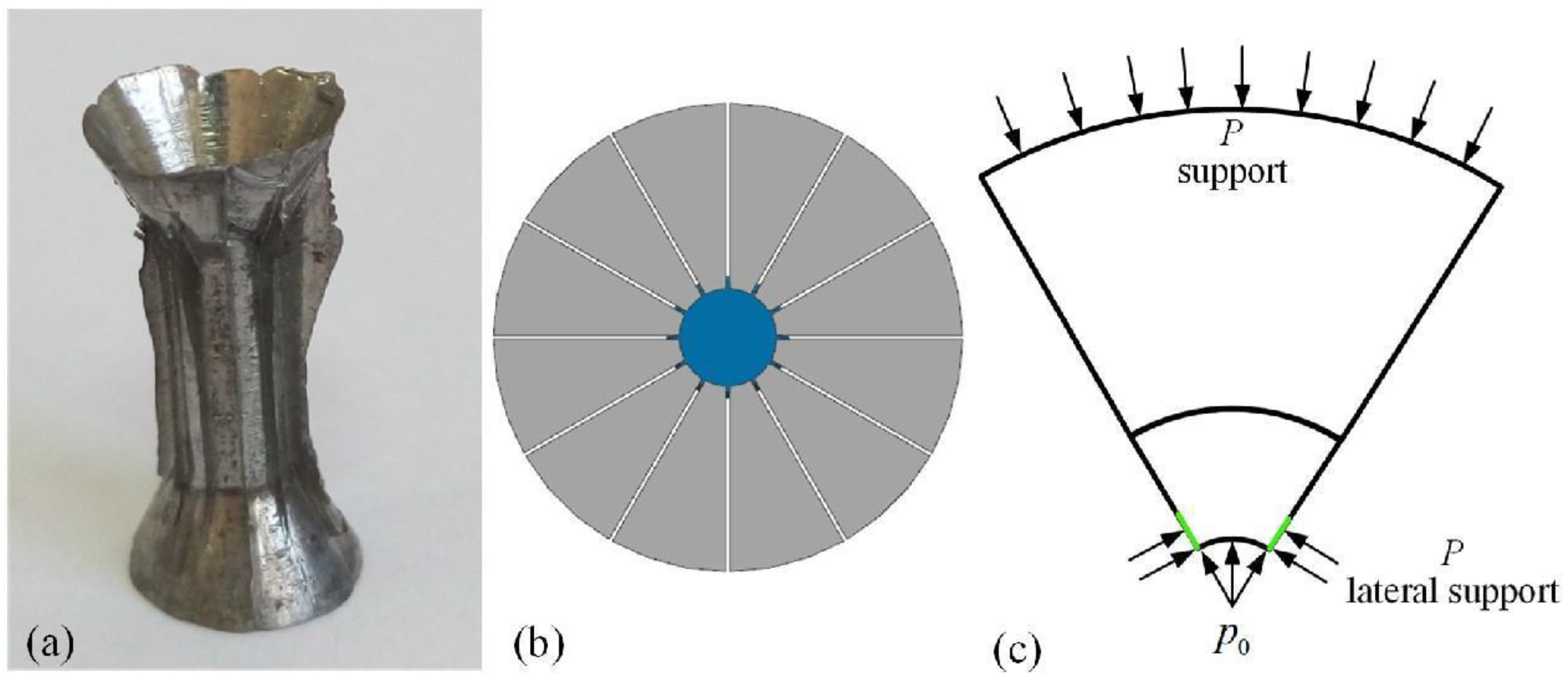
4.1. The Belt-Type Die
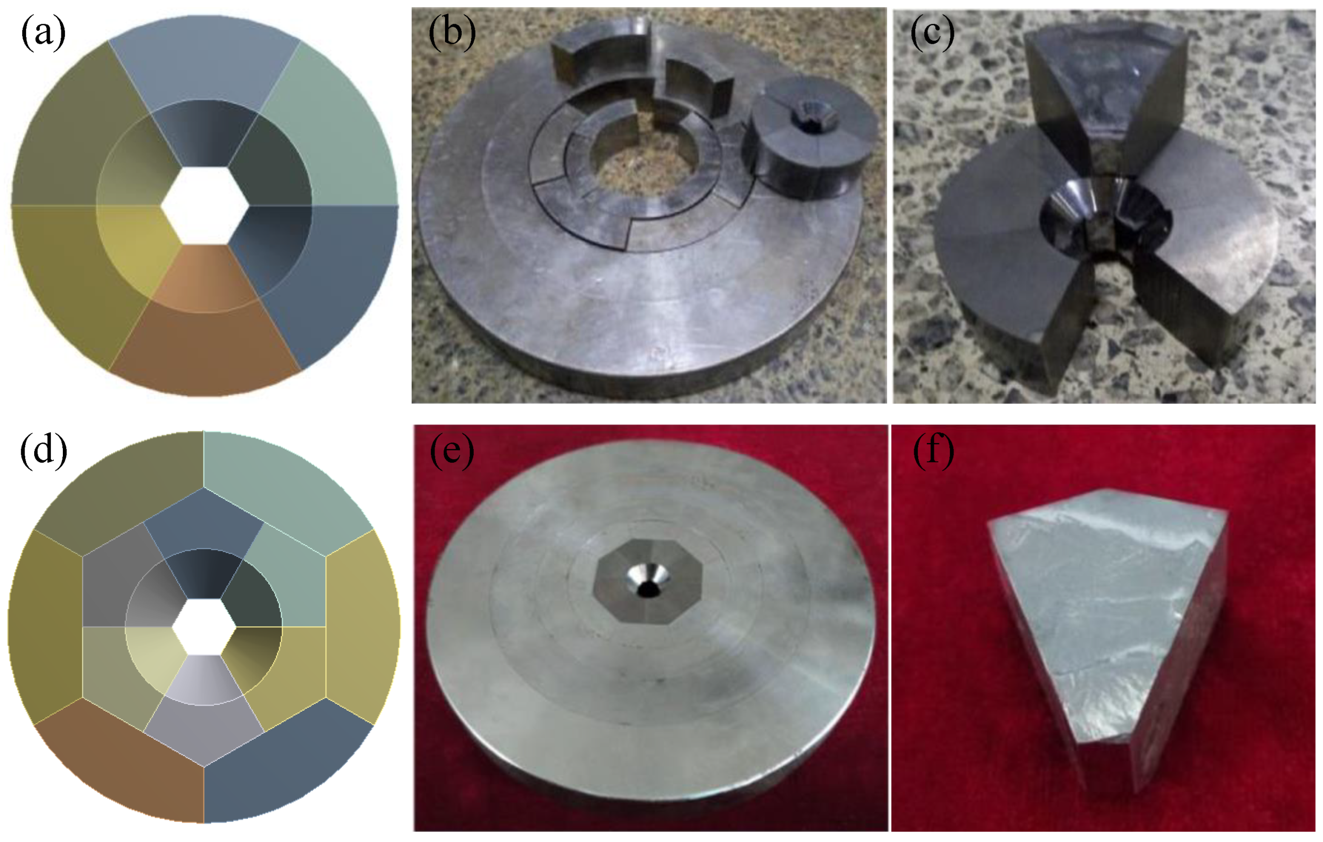
Figure 5 shows the three main stresses σ 1 , σ 2 ,   and   σ 3 , and the average stress σ m , along the path of the belt cylinder under the application of 6500 MPa of force to the inner wall of the cylinder. As shown in the figure, the cylinder of the BTD was a continuous whole in the circumferential direction. Therefore, the first principal stress of the belt cylinder was very large and gradually increased from 1655 to 3506 MPa, after which it remained unchanged. The second principal stress gradually increased from −5767 to −3047 MPa and then remained unchanged. The third principal stress was approximately −6400 MPa, which was basically equal to the pressure applied to the inner wall of the cylinder.
As indicated in Figure 5, the first principal stress σ 1 was much larger than the average stress σ m . Moreover, the second and third principal stresses were less than σ m . Therefore, σ 1 = σ 1 σ m > 0 ,   σ 2 = σ 2 σ m < 0, and σ 3 = σ 3 σ m < 0 ; this corresponds to J 3 = σ 1 σ 2 σ 3 > 0. From this, it can be determined that the belt-type cylinder was in a state of tensile deformation after being subjected to force.
For any state of stress, the principal stress and the shear stress on any plane can be described using the three-dimensional Mohr stress circle. After examining the three principal stresses, the results revealed that σ 1 > σ 2 > σ 3 , and the Mohr stress circles obtained for the stress states are presented in Figure 6. The shear stress can be calculated as follows.
τ 13 = σ 1 σ 3 2 τ 23 = σ 2 σ 3 2 τ 12 = σ 1 σ 2 2
From this, the three shear stresses were determined, and the value of τ 13 was found to be the highest. The von Mises stress of the cylinder is also an important criterion for judging the failure of the cylinder and can be determined using σ 1 , σ 2 ,   and   σ 3 as follows.
σ V M = 1 2 σ 1 σ 2 2 + σ 1 σ 3 2 + σ 2 σ 3 2
The value of the third principal stress is determined by the pressure inside the cavity. When exploring how to reduce the stress performance of the cylinder, efforts should be made to reduce the first principal stress, which will significantly reduce the maximum shear stress and, to some extent, reduce the von Mises stress. At the cylinder cavity pressure of 6500 MPa, the von Mises stress value of the belt cylinder gradually increased from 7787 MPa (point 1) to 8705 MPa (point 2). From point 2 to point 3, the value remained at almost 8705 MPa, and the maximum shear stress value was 4938 MPa. It can be seen that at this time, the first principal stress, the von Mises stress, and the maximum shear stress of the BTD were much greater than the corresponding failure limit. However, the rate of increase of the first principal stress was significantly higher than those of the von Mises stress and maximum shear stress, as the first principal stress was the main reason for the changes in these two stress values. Therefore, it can be preliminarily judged that the cause of the failure of the BTD was the continuous circumferential direction of the integral pressure cylinder, which led to an excessive first principal stress and the circumferential tensile failure of the cylinder.
To confirm the failure mode and bearing capacity of the BTD, a corresponding die was designed and processed according to the dimensions exhibited in Figure 2. The cylinder was made of YG8 carbide, and the outer supporting ring was made of 45CrNiMoVA high-strength steel. The sample subjected to experimentation was made of pure iron. A hydraulic press was used to carry out the experiments and the oil pressures were read when the dies fractured. Figure 7 presents the diagram of the die after destruction. When the oil pressure was 7.2 MPa (the bearing load was 564.5 KN), the belt cylinder burst upward, which is consistent with the theoretical analysis results. Therefore, it can be determined that the overall belt cylinder contributed to an excessive first principal stress, which then led to circumferential cracking damage.

4.2. The Split Die

From the previous subsection, it can be seen that the main failure of the BTD is caused by excessive circumferential stress. Even if the supporting ring provides sufficient external support force, it cannot prevent the radial failure of the inner wall of the pressure cylinder. Therefore, to avoid the disadvantage of a large circumferential tensile stress of the BTD, the concept of a discretized cylinder is proposed through reducing the circumferential tensile stress of the cylinder and increasing the cavity pressure. The discretized cylinder is not continuous in the circumferential direction, which can reduce both the circumferential stress and the shear stress. The designed multilayer stagger-split die (MSSD) is depicted in Figure 8. When the pressure on the inner wall of the cylinder is transmitted radially, the supporting ring bears a large amount of pressure. The discrete supporting ring can gradually reduce the pressure while ensuring safety. The pressure ultimately transmitted to the outer supporting ring is significantly reduced, thus improving the safety and stability of the die. The common feature of the design of the MSSD and the BTD is that, of the entire die, the pressure cylinder is the first component of the entire die to be damaged. Therefore, the stress and damage characteristics of the cylinder are mainly analyzed in this section.
The cylinder of the BTD is divided into six equal sections in the circumferential direction, each with an angle of 60°, which are combined to form a split cylinder. The structure of the cylinder is presented in Figure 9. The size was the same as that of the BTD, and the interference between the layers is, respectively, 0, 0.15, 0.3, and 0.35 mm from the inner to the outer layer. In the numerical simulation process, because the force and stress behaviors of the six sections were identical, only one section was analyzed. When the pressure on the inner wall of the cylinder was 6500 MPa, the first principal stress of the split cylinder was much less than that of the BTD, and the value was basically maintained at 50 MPa. The second principal stress gradually increased from −5908 to −4014 MPa, and the third principal stress value was the same as that of the BTD, which was basically maintained at −6400 MPa. The three principal stresses and the average stress diagram were obtained, as exhibited in Figure 10.
As was the case with the BTD, the first principal stress σ 1 of the split cylinder was greater than the average stress σ m . The second principal stress σ 2 and the third principal stress σ 3 were less than the average stress σ m . Therefore, σ 1 = σ 1 σ m > 0 ,   σ 2 = σ 2 σ m < 0, and σ 3 = σ 3 σ m < 0 ; this corresponds to J 3 = σ 1 σ 2 σ 3 > 0. From this, it can be seen that the split cylinder was still in a state of tensile deformation, but only the inner wall of the pressure cylinder was in a state of tensile deformation. Moreover, the amount of deformation was minor and was not sufficient to crack the split sector block. The failure mode of the split cylinder requires further discussion.
Compared with the BTD, excluding the significant reduction in the first principal stress, the third principal stress basically exhibited no change, while the second principal stress experienced a certain change. The three-dimensional Mohr stress circle is shown in Figure 10. The reduction in the first principal stress led to a significant reduction in the maximum shear stress. The von Mises stress of the MSSD gradually decreased from 6112 MPa (point 1) to 5645 MPa (point 2), and from point 2 to point 3, the value remained at approximately 5600 MPa, with a maximum shear stress of 3232 MPa. Both the von Mises stress and the maximum shear stress were much smaller than those of the BTD. According to the von Mises stress Equation (11), the change in the von Mises stress value of the MSSD was mainly caused by the change of the first principal stress. Therefore, due to the circumferential discontinuity, the MSSD can significantly reduce the first principal stress, reduce the maximum shear stress and von Mises stress, and significantly improve the pressure-bearing capacity.
The numerical simulation results reveal that the pressure capacity of the MSSD was about 6700 MPa (the theoretical value is about 8.4 MPa). To prove the accuracy of the theoretical results, a destructive experiment for the UHP die was conducted, as shown in Figure 11. In fact, when the pressure cylinder was broken, the oil pressure was 9.1 MPa (the pressure was 713.4 KN). This experimental value was greater than the theoretical value, which is attributable to two reasons. First, due to the small assembly interference of the MSSD, the radial displacement of the cylinder was greater than that of the BTD, resulting in an increase in the internal area of the cavity and an increase in the hydraulic pressure of the hydraulic press. The second reason is that the radial displacement of the split cylinder caused gaps between adjacent sector blocks, and the medium flowed into the gap after being subjected to force (as shown in Figure 12). The medium in the gap exerts a certain support force on the side of the sector block, and the pressure-bearing capacity will be significantly improved even if the lateral support force is very small. This is because the inner face of the sector block cylinder is in a three-dimensional compression, and the third invariant of the deviatoric stress tensor J 3 < 0 . The inner face of the sector block cylinder is in a state of compressive deformation; this is in line with the mechanical properties of hard carbide materials, which are resistant to high pressure but not tension. The numerical simulation and theoretical analysis results indicate that even when considering the lateral support force of the medium, the von Mises stress of the split cylinder is the first to reach the failure limit. The radial middle position of the sector block is destroyed at 45°, and the failure mode conforms to the fourth strength theory. An excessive von Mises stress leads to the accumulation of internal distortion energy in the hard carbide, resulting in failure.
To further improve the bearing capacity of the radial split cylinder, two types of cylinders with positive polygonal cavities were designed, as shown in Figure 13. The first cylinder was a radial split cylinder, but the front face of the sector block was changed from a circular arc to a plane, and the cavity was changed from a cylindrical surface to a regular polygon. The radial split cylinder will produce a certain amount of radial displacement after being stressed, and the outer supporting ring will provide a lateral support force. Therefore, a second radial split cylinder with a regular polygon cavity was designed. The numerical simulation and experimental results revealed that the pressure-bearing capacities of these two types of cylinders were slightly improved as compared to that of the original radial split cylinder, but the improvement was insignificant. The pressure-bearing capacity was improved because the first principal stress of the regular polygon cavity was slightly lower than that of the radial split cylinder, resulting in the reduction in the maximum shear stress and von Mises stress. However, this type of cylinder still has the disadvantage of a radial split cylinder, which means the cylinder will be in a tensile state after being subjected to force, thus limiting the continued increase in pressure.

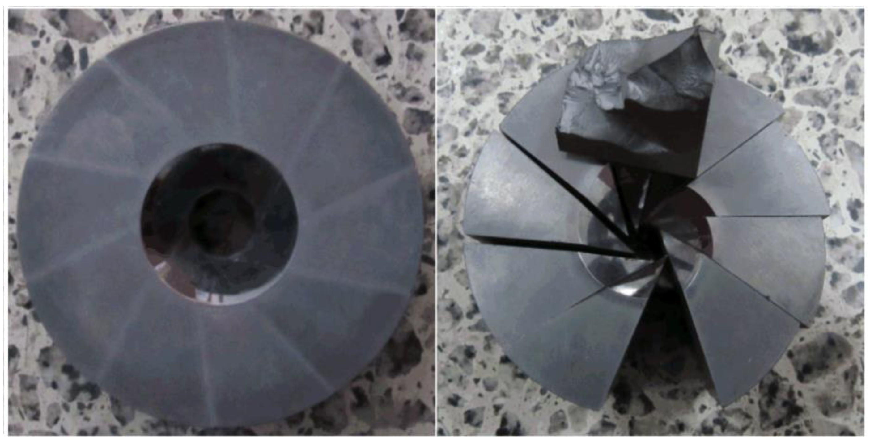
4.3. The Tangential Split Die

Due to the circumferential discontinuity, the first principal stress of the split cylinder can be significantly reduced; this leads to an effective reduction in the von Mises stress and maximum shear stress, and an effective improvement in the pressure-bearing capacity. The stress performance of the front face of the cylinder proves that the third invariant of the deviatoric stress tensor of the front face J 3   > 0, but the front face of the cylinder remains in a tensile state. However, the medium is squeezed into the gap of the sector block, which provides lateral support force; consequently, the third invariant of the deviatoric stress tensor of the front face J 3 < 0. Furthermore, the front face is in a three-dimensional compressive state, which can effectively improve the pressure-bearing capacity of the pressure cylinder. Therefore, the three-dimensional compression of the cylinder can significantly improve the pressure-bearing capacity, which is an effective measure through which to increase the cavity pressure. For this purpose, a tangential split cylinder was designed, as shown in Figure 14. The front face of the tangential split cylinder is perpendicular to the radial direction and is divided along the tangent direction of the circular inner cavity. The cylinder is divided into 10 sections. In this way, the cavity is no longer a cylindrical structure; instead, it is a cylindrical structure characterized by a positive decagonal shape. When the cavity is under pressure, there is mutual friction and compression between adjacent segmented blocks of this block structure. This not only eliminates the circumferential tensile stress on the inner wall of the cylinder, but also generates significant compressive stress on the inner wall, causing the tangential segmented blocks to be in a three-dimensional compression state. This state is very beneficial for hard carbide materials and can fully utilize their properties under pressure.
The dimensions of the UHP die for the tangential split die are the same as those of the BTD mentioned previously. The interference between the layers from the inner to the outer layer is, respectively, 0.1, 0.15, 0.3, and 0.35 mm, and the diameter of the circle tangent to the positive decagonal cavity is 10 mm. In the numerical simulation process, the stress behavior of the 10 tangential segmented blocks was the same. When a pressure of 6500 MPa was applied to the inner face of the tangential split die, the first, second, and third principal stress values were approximately −3750, −4700, and −6750 MPa, respectively. Statistical analysis was performed on the three principal stresses to obtain the average stress σ m . As shown in Figure 15, the first principal stress of the tangential split die σ 1 and the second principal stress σ 2 were greater than the average stress σ m . The third principal stress σ 3 was less than the average stress σ m . Therefore, σ 1 = σ 1 σ m > 0 , σ 2 = σ 2 σ m > 0, and σ 3 = σ 3 σ m < 0 ; this corresponds to J 3 = σ 1 σ 2 σ 3 < 0. From this, it can be determined that the tangential split die was in a state of compressive deformation, which is consistent with the results of the previous analysis. Accordingly, the properties of hard alloy materials can be fully utilized.
Compared with that of the split die, the first principal stress of the tangential split die continued to decrease. According to Equations (10) and (11), the maximum shear stress and von Mises stress of the tangential split die were less than those of the split die, corresponding to a higher pressure-bearing capacity. The numerical simulation results demonstrated that the maximum von Mises stress of the tangential split die was 4560 MPa, and the maximum shear stress was 2940 MPa. With the continued increase in the cavity pressure, the maximum shear stress and von Mises stress continued to increase, but the maximum shear stress was the first to reach the failure limit (3250 MPa). The theoretical failure mode was found to conform to the fourth strength theory. A destructive test was conducted to demonstrate the accuracy of the theoretical and numerical simulation results. The tangential split die was damaged under the hydraulic press pressure of 10.5 MPa (with a pressure-bearing capacity of 823.2 KN). The die failure morphology is shown in Figure 16 and is consistent with the theoretical analysis results. The pressure-bearing capacity of the tangential split die was therefore significantly improved.
The results of the destructive experiments indicate that regardless of the type of split die failure, only one or several split blocks failed, while the remaining split blocks remained intact and could still be used after replacing the broken split blocks. Although the forces on each segmented block were the same in the numerical simulation, they did not fail simultaneously. This was due to some inevitable material defects, instantaneous stress concentration, and other phenomena, which caused the die to fail first in some segmented blocks under extreme pressure. Moreover, the theoretical analysis and experimental results prove that designing the BTD as a split-type die can reduce the first principal stress σ 1 . Additionally, while it is feasible to improve the bearing capacity of the die through reducing the maximum shear stress and von Mises stress, the third invariant of the deviatoric stress tensor J 3 > 0 restricts the improvement of the bearing capacity. The theoretical analysis and experimental results confirmed that the third invariant of the deviator stress tensor J 3 < 0 can fully utilize the properties of hard carbide materials and further improve the pressure-bearing capacity. Based on the research, several types of UHP dies were designed, and their stress and failure modes of the dies were analyzed. Moreover, the accuracy of the theoretical analysis was proven via experiments. More importantly, an effective optimization design method was provided for the development of BTDs, and its accuracy was verified via numerical simulation, theoretical analysis, and experiments.

5. Conclusions

Via theoretical analysis, numerical simulation, and destructive experiments, the stress distribution, pressure-bearing capacity, and failure principle of various BTDs were compared and analyzed. The following conclusions were obtained from the results.
(1) A split cylinder can significantly reduce the first principal stress, thereby effectively reducing the maximum shear stress and von Mises stress values, and ultimately improving the pressure-bearing capacity of the cavity.
(2) The positive and negative values of the third invariant of the deviatoric stress tensor J 3 determine the deformation mode of the pressure cylinder. When J 3 > 0, the cylinder is in a tensile deformation state, and when J 3   < 0, the pressure cylinder is in a compressive deformation state.
(3) The circumferential stress causes the failure of the BTD, the von Mises stress leads to the failure of the split die, and the maximum shear stress leads to the failure of the tangential split die.
(4) When the third invariant of the deviatoric stress tensor J 3 < 0, the pressure-bearing capacity of the tangential split die is significantly improved, thus providing an effective optimization design theory and method for BTD production.

Author Contributions

Conceptualization, M.L.; Methodology, B.W. and M.L.; Software, B.W.; Formal analysis, Z.S.; Resources, M.L.; Data curation, Z.S.; Writing—original draft, Z.S.; Writing—review & editing, B.W.; Funding acquisition, B.W. All authors have read and agreed to the published version of the manuscript.

Funding

This research was funded by by the National Key Research and Development Program of China (2021YFD2000502), the Shandong Province Technology Innovation Capability Enhancement Project (2023TSGC0536), and the Key Research and Development Program of Rizhao (2023ZDYF010114).

Data Availability Statement

Data supporting the reported results can be found from the authors.

Conflicts of Interest

The authors declare no conflict of interest.

References

  1. Hall, H.T. Ultra-High-Pressure, High-Temperature Apparatus: The “Belt”. Rev. Sci. Instrum. 1960, 31, 125–131. [Google Scholar] [CrossRef]
  2. Bridgman, P.W. The Resistance of 72 Elements, Alloys and Compounds to 100,000 kg/cm2; Papers 169–199; Harvard University Press: Cambridge, MA, USA, 1964; pp. 4113–4197. [Google Scholar]
  3. Li, S.H.; Li, J.L.; Ge, J.Z.; Gao, X. Design and Research of Double-Layered Cemented Carbide Novel High-Pressure Die. Int. J. Eng. Res. Afr. 2021, 53, 42–52. [Google Scholar] [CrossRef]
  4. Guan, W.; Gao, G.; Yu, Y.; Zhuo, T. Theoretical, experimental and numerical investigations on the energy absorption of splitting multiple circular tubes under impact loading. Thin-Walled Struct. 2020, 155, 106916. [Google Scholar] [CrossRef]
  5. Kawai, N.; Endo, S. The generation of ultrahigh hydrostatic pressures by a split sphere apparatus. Rev. Sci. Instrum. 1970, 41, 1178–1181. [Google Scholar] [CrossRef]
  6. Hall, H.T. High pressure apparatus: Ram-in-tie-bar multianvil presses. Rev. Phys. Chem. Jpn. 1967, 37, 63–71. [Google Scholar]
  7. Hall, H.T. Some high-pressure, high-temperature apparatus design considerations: Equipment for use at 100,000 atmospheres and 3000 C. Rev. Sci. Instrum. 1958, 29, 267–275. [Google Scholar] [CrossRef]
  8. Yang, Y.; Li, M.; Wang, B. Study on stress distribution of tangent split high pressure apparatus and its pressure bearing capacity. Diam. Relat. Mater. 2015, 58, 180–184. [Google Scholar] [CrossRef]
  9. Xu, B.; Tian, Y. Superhard materials: Recent research progress and prospects. Sci. China Mater. 2015, 58, 132–142. [Google Scholar] [CrossRef]
  10. Zhao, L.; Li, M.; Li, R.; Qu, E.; Wang, L.; Yi, Z.; Zheng, C. Stress analysis of the multi-layer stagger-split die for synthesizing gem quality large single crystal diamond. Diam. Relat. Mater. 2018, 83, 54–59. [Google Scholar] [CrossRef]
  11. Bassett, W.A. Diamond anvil cell, 50th birthday. High Press. Res. 2009, 29, 163–186. [Google Scholar] [CrossRef]
  12. Liebermann, R.C. Multi-anvil, high pressure apparatus: A half-century of development and progress. High Press. Res. 2011, 31, 493–532. [Google Scholar] [CrossRef]
  13. Zhao, L.; Wu, N.; Li, M.; Liang, X.; Gu, Z. Stress analysis and experiment on a split-type ultra-high-pressure die for synthesizing diamond. Rev. Sci. Instrum. 2021, 92, 103903. [Google Scholar] [CrossRef]
  14. Katsura, T.; Funakoshi, K.; Kubo, A.; Nishiyama, N.; Tange, Y.; Sueda, Y.-I.; Kubo, T.; Utsumi, W. A large-volume high-pressure and high-temperature apparatus for in situ X-ray observation,‘SPEED-Mk. II’. Phys. Earth Planet. Inter. 2004, 143, 497–506. [Google Scholar] [CrossRef]
  15. Xu, J.A.; Mao, H.K.; Bell, P.M. High-pressure ruby and diamond fluorescence: Observations at 0.21 to 0.55 terapascal. Science 1986, 232, 1404–1406. [Google Scholar] [CrossRef] [PubMed]
  16. Wang, R.; Lei, T.; He, X.; Jin, W. Numerical optimization of billet diameter in the wide-spread and split extrusion process. J. Phys. Conf. Ser. 2023, 2483, 012001. [Google Scholar] [CrossRef]
  17. Qiang, W.; Fang, H.; Wei, L.; Li, D.; Wang, Z.R. Strength analysis and optimization for both the cylinder and the anvil of a BELT-type ultra-high-pressure apparatus by FEM. J. Mater. Process. Technol. 1995, 55, 5–10. [Google Scholar] [CrossRef]
  18. Ichida, Y.; Ohfuji, H.; Irifune, T.; Kunimoto, T.; Kojima, Y.; Shinmei, T. Synthesis of coarse-grain-dispersed nano-polycrystalline cubic boron nitride by direct transformation under ultrahigh pressure. Diam. Relat. Mater. 2017, 77, 25–34. [Google Scholar] [CrossRef]
  19. Chen, Z.; Zhang, Z.; Zheng, J.; Xue, Y. Radially loading rotary extrusion for manufacturing large-size conical cylinders with inner transverse high ribs. Chin. J. Aeronaut. 2023, 36, 582–594. [Google Scholar] [CrossRef]
  20. Moss, W.C.; Goettel, K.A. The stability of a sample in a diamond anvil cell. J. Appl. Phys. 1987, 61, 4951–4954. [Google Scholar] [CrossRef]
  21. Yi, Z.; Fu, W.; Li, M.; Li, R.; Zhao, L.; Wang, L.Y. Numerical simulation and experimental verification of a novel double-layered split die for high-pressure apparatus used for synthesizing superhard materials. Int. J. Miner. Metall. Mater. 2019, 26, 377–385. [Google Scholar] [CrossRef]
  22. Choi, J.; Choi, J.; Lee, K.; Hur, N.; Kim, N. Fatigue Life Prediction Methodology of Hot Work Tool Steel Dies for High-Pressure Die Casting Based on Thermal Stress Analysis. Metals 2022, 12, 1744. [Google Scholar] [CrossRef]
  23. Liu, X.Y. High pressure synthesis and preparation of inorganic materials. In Modern Inorganic Synthetic Chemistry; Elsevier: Amsterdam, The Netherlands, 2017; pp. 105–141. [Google Scholar]
  24. Vrbka, J.; Knesl, Z. High Pressure Geoscience and Material Synthesis; Akademie-Verlag: Berlin, Germany, 1988; p. 234. [Google Scholar]
  25. Vrbka, J.; Knésl, Z. Philosophy and reality of strength design of the BELT chamber by finite element method. In High Pressure Geoscience and Material Synthesis; Akademie-Verlag: Berlin, Germany, 1988; pp. 234–239. [Google Scholar]
  26. Xu, S.; Zhao, D.; Gao, X.; Liu, C.; Huang, W.; Meng, X. Numerical simulation and research of the split ultrahigh pressure cylinder. IOP Conf. Ser. Mater. Sci. Eng. 2020, 768, 042043. [Google Scholar] [CrossRef]
  27. Longjian, X.; Artem, C.; Takayuki, I.; Bondar, D.; Nishida, K.; Chen, Z.; Bhat, S.; Farla, R.; Higo, Y.; Tange, Y.; et al. Simultaneous generation of ultrahigh pressure and temperature to 50 GPa and 3300 K in multi-anvil apparatus. Rev. Sci. Instrum. 2021, 92, 103902. [Google Scholar]
  28. Klünsner, T.; Wurster, S.; Supancic, P.; Ebner, R.; Jenko, M.; Glätzle, J.; Püschel, L.; Pippan, R. Effect of specimen size on the tensile strength of WC–Co hard metal. Acta Mater. 2011, 59, 4244–4252. [Google Scholar] [CrossRef]
  29. Xiao, S.; Luan, X.; Liang, Z.; Wang, X.; Zhou, T.; Ding, Y. Fracture Analysis of Ultrahigh-Strength Steel Based on Split Hopkinson Pressure Bar Test. Metals 2022, 12, 628. [Google Scholar] [CrossRef]
  30. Wang, B.; Mingzhe, L.I.; Liu, Z.; Han, X. A Novel Tangential Split-Belt Ultrahigh Pressure Apparatus. Gaoya Wuli Xuebao/Chin. J. High Press. Phys. 2019, 33, 64–69. [Google Scholar]
  31. Xinyu, H.; Guangdong, Z.; Tong, D. Improved Optimization of a Coextrusion Die with a Complex Geometry Using the Coupling Inverse Design Method. Polymers 2023, 15, 3310. [Google Scholar]
  32. Wang, B.; Li, M.; Liu, Z.; Han, X. Numerical Simulation and Experiment on New Multilayer Stagger-Split Die of Ultra-High Pressure Apparatus. Gaoya Wuli Xuebao/Chin. J. High Press. Phys. 2018, 32, 27–32. [Google Scholar]
Figure 1. A schematic diagram of the belt-type high-pressure apparatus.
Metals 13 01593 g001
Figure 2. The geometric sizes of the two different types of UHP dies.
Metals 13 01593 g002
Figure 3. Schematic diagram of boundary conditions: (a) The Belt-type die, (b) The split die.
Metals 13 01593 g003
Figure 4. The elements plot of the cylinder and homogeneous unit’s geometry of solid 186.
Metals 13 01593 g004
Figure 5. The principal stress along the path of the belt cylinder.
Metals 13 01593 g005
Figure 6. The three-dimensional Mohr’s circle of stress.
Metals 13 01593 g006
Figure 7. A physical diagram of the belt-type die.
Metals 13 01593 g007
Figure 8. A schematic diagram of the MSSD high-pressure apparatus.
Metals 13 01593 g008
Figure 9. A schematic diagram of the split cylinder.
Metals 13 01593 g009
Figure 10. The principal stress along the path of the split cylinder.
Metals 13 01593 g010
Figure 11. A physical diagram of the MSSD.
Metals 13 01593 g011
Figure 12. A schematic diagram of the lateral support for the split cylinder. (a) pure iron specimen after extrusion (b) the deformation of compressed specimen (c) the lateral support principle for the split cylinder.
Metals 13 01593 g012
Figure 13. The vertical polygon cavity of the radial split cylinder UHP die. (a) a schematic diagram of the split cylinder with plane surface (b) a physical diagram of the split cylinder with plane surface (c) the damaged die of the split cylinder with plane surface (d) a schematic diagram of the double-layered split cylinder with plane surface (e) a physical diagram of the double-layered split cylinder with plane surface (f) the damaged die of the double-layered split cylinder with plane surface.
Metals 13 01593 g013
Figure 14. A schematic diagram of the tangential split cylinder.
Metals 13 01593 g014
Figure 15. The principal stress along the path of the tangential split cylinder.
Metals 13 01593 g015
Figure 16. The physical diagram of the tangential split die.
Metals 13 01593 g016
Disclaimer/Publisher’s Note: The statements, opinions and data contained in all publications are solely those of the individual author(s) and contributor(s) and not of MDPI and/or the editor(s). MDPI and/or the editor(s) disclaim responsibility for any injury to people or property resulting from any ideas, methods, instructions or products referred to in the content.

