
Long Sump Life Effects of a Naturally Aged Bio-Ester Oil Emulsion on Tool Wear in Finish Turning a Ni-Based Superalloy
 , , , , , and
Abstract
:1. Introduction
Overview of the Approach Taken
2. Materials and Methods
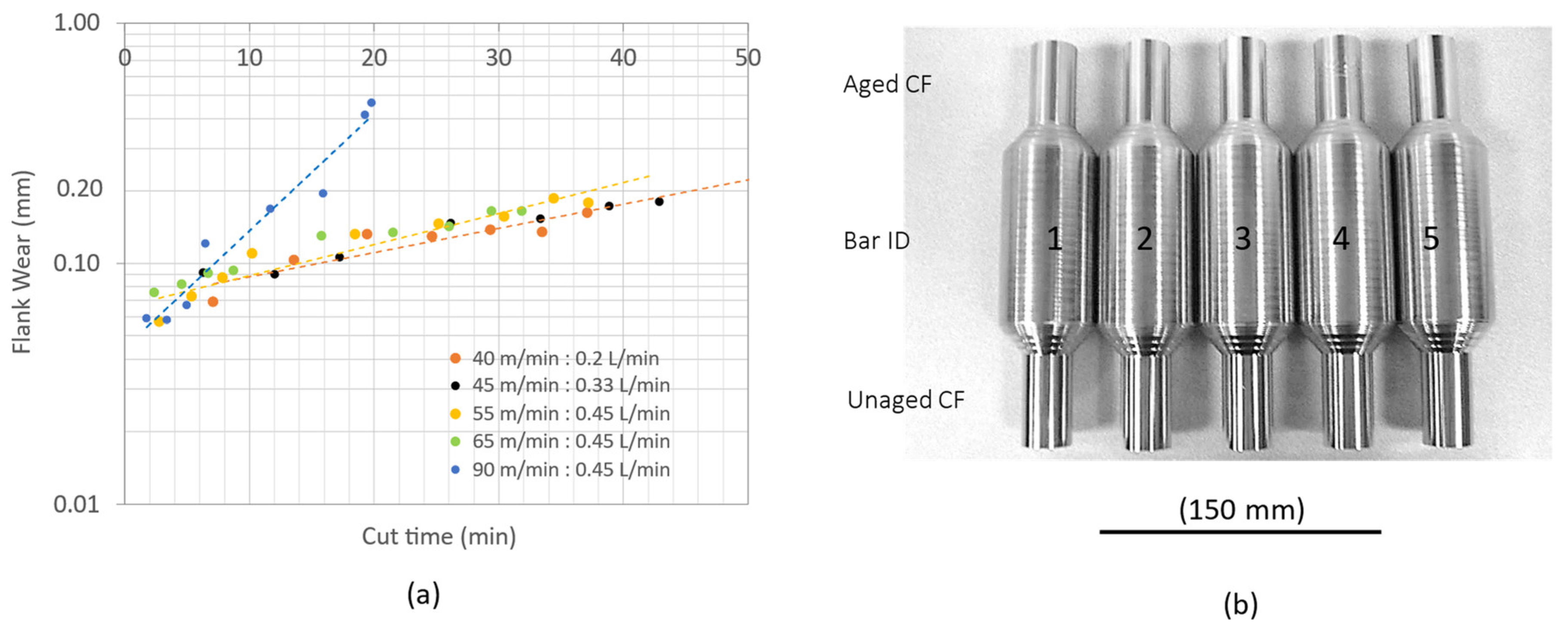
2.1. Workpieces
2.2. Machine Tool
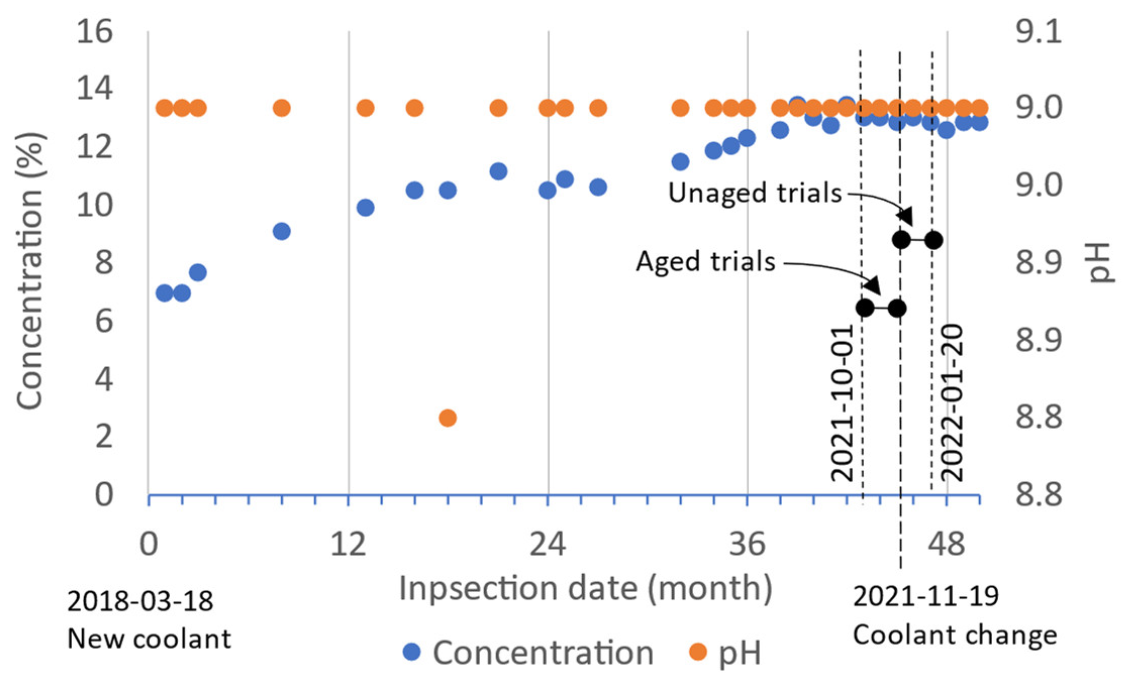
2.3. Cutting Fluid
2.4. Tool Holder and Tip Insert
2.5. Set-Up and Method for Experiments
2.6. Turning Parameters for This Study
2.7. Instruments
3. Results and Discussion
3.1. Stability of Machine Tool and Workpiece, Using Turning Protocol
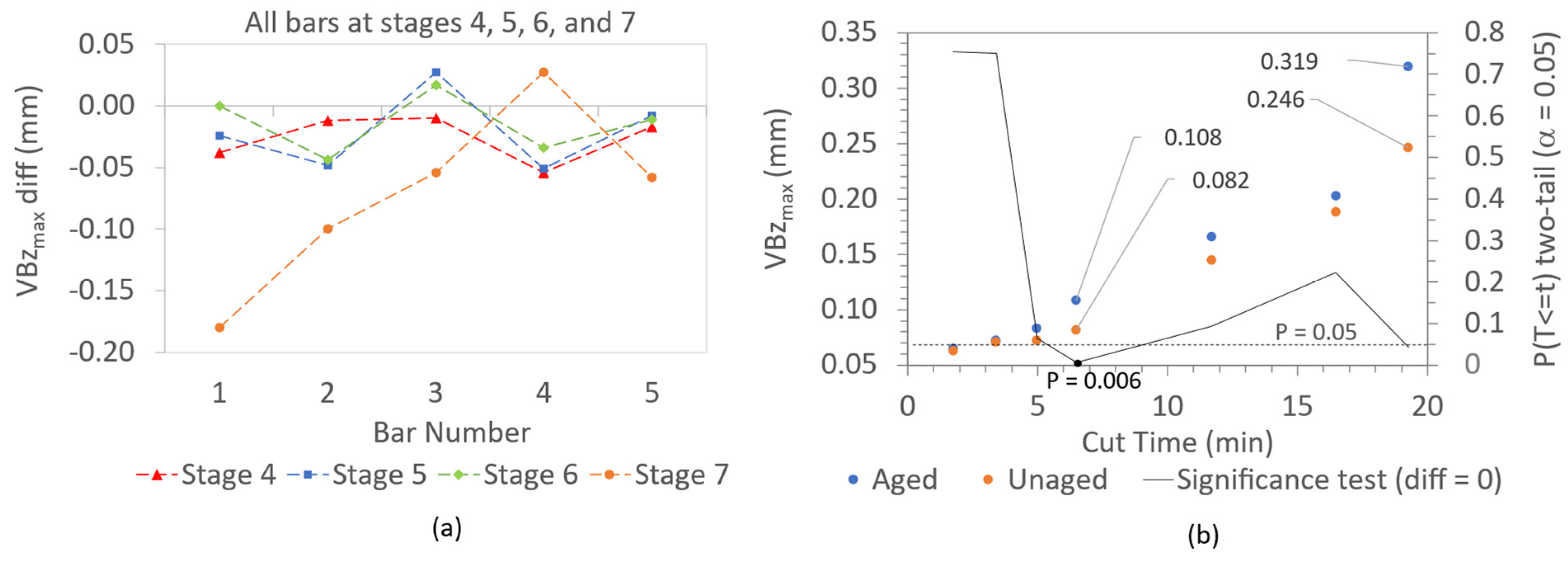
3.2. Comparing Aged and Unaged Coolant Performance
3.2.1. Flank Wear
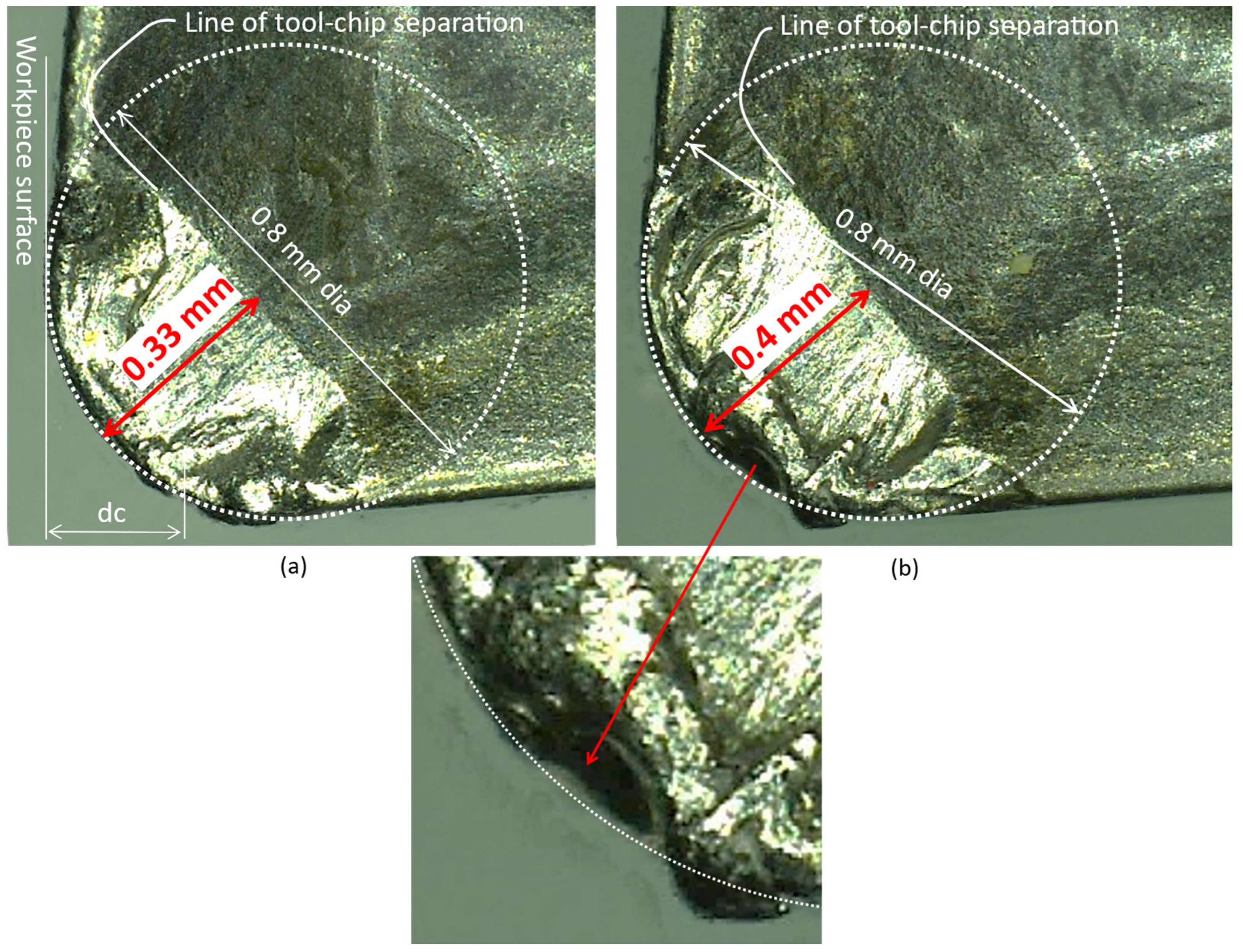
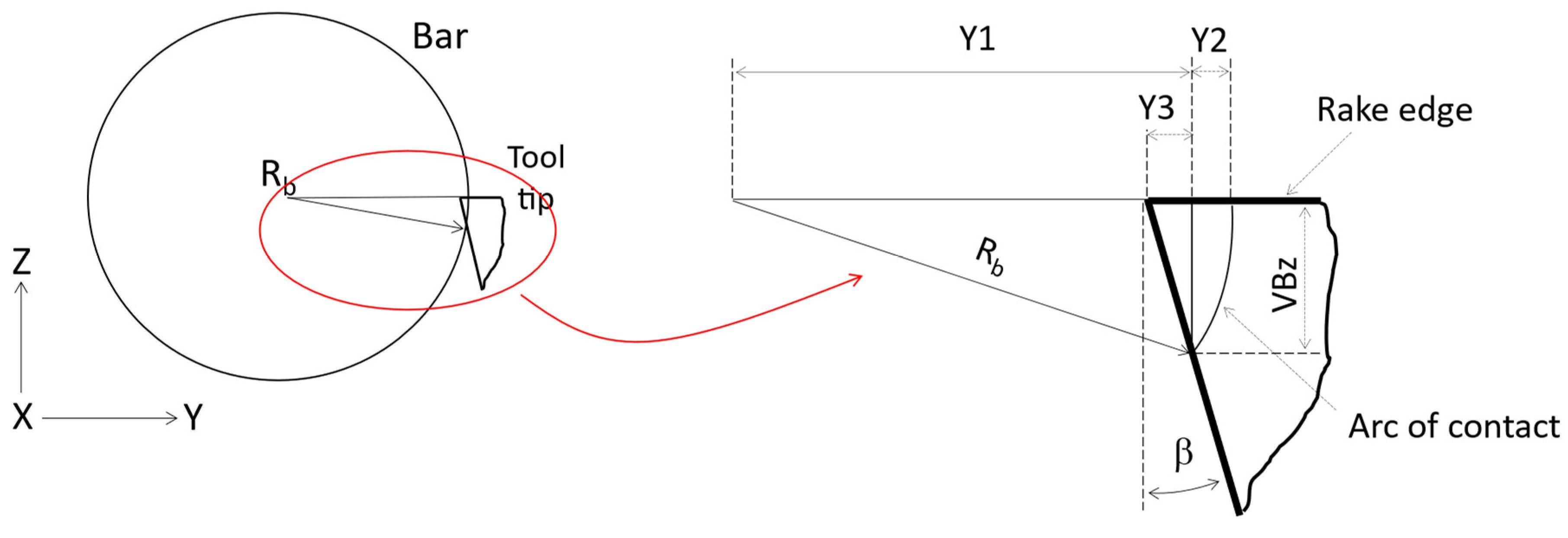
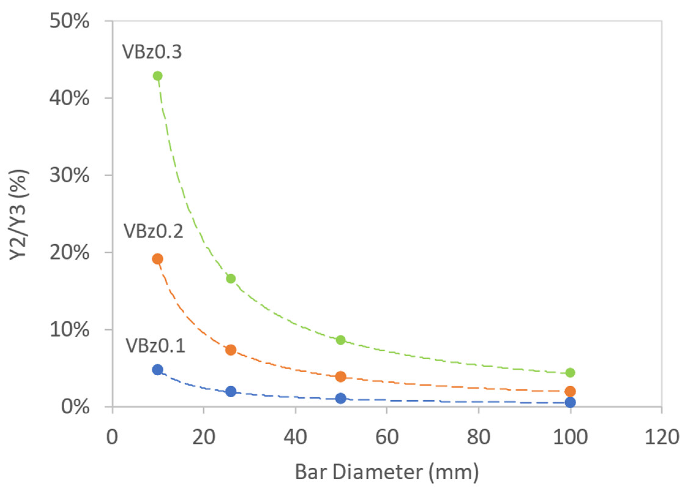
3.2.2. Effect of Workpiece Diameter on Tool Flank Wear Measurement
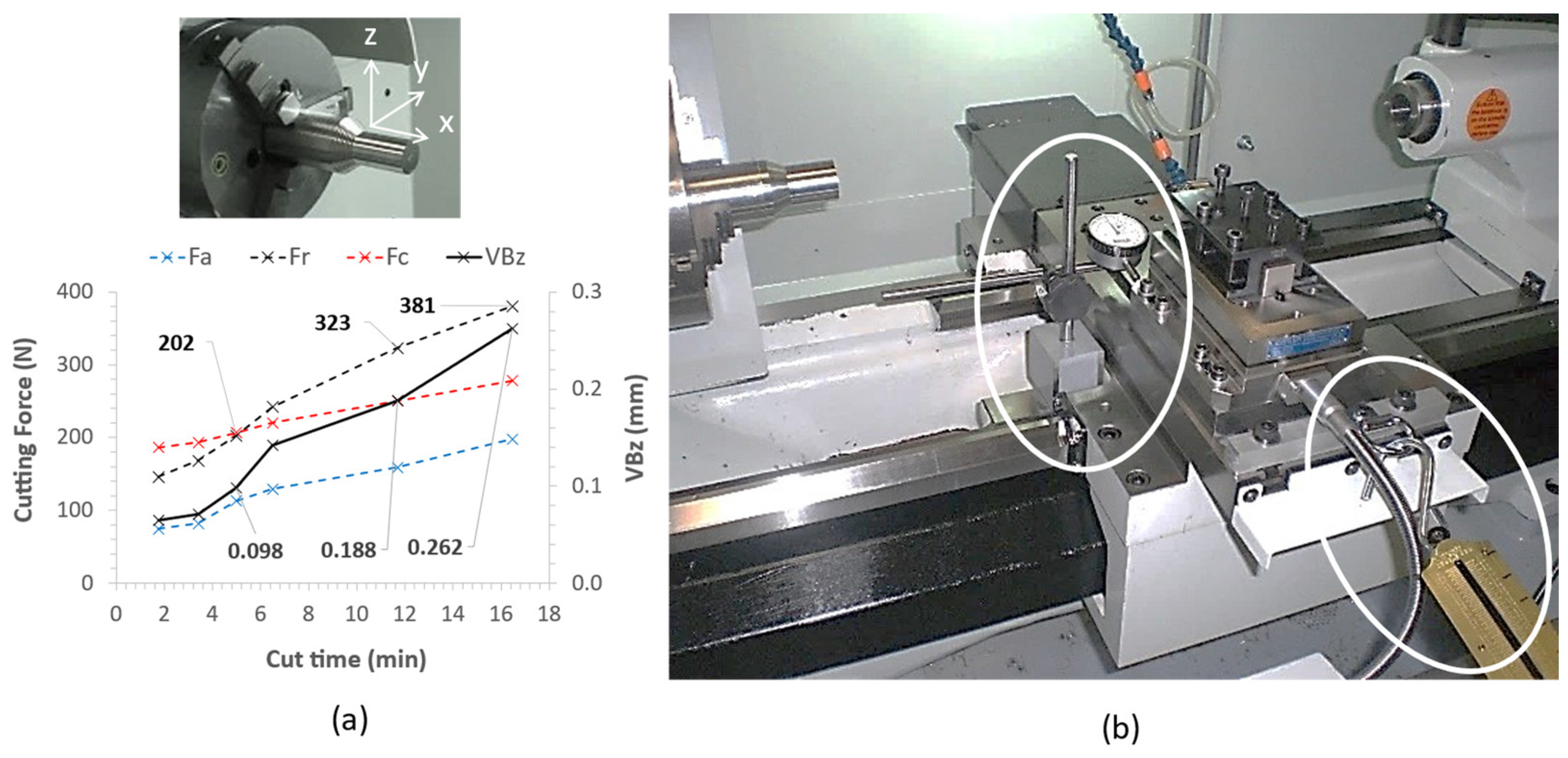
3.2.3. Cutting Forces
3.2.4. Surface Work Hardening
3.2.5. Chip Forms
3.2.6. Temperature
4. Analysis of Coolant Samples
4.1. Element Analysis
4.2. Contamination
4.3. Chemistry
4.4. Microorganism Effects
4.5. Nonwater Hardening Ions
5. Conclusions
- o
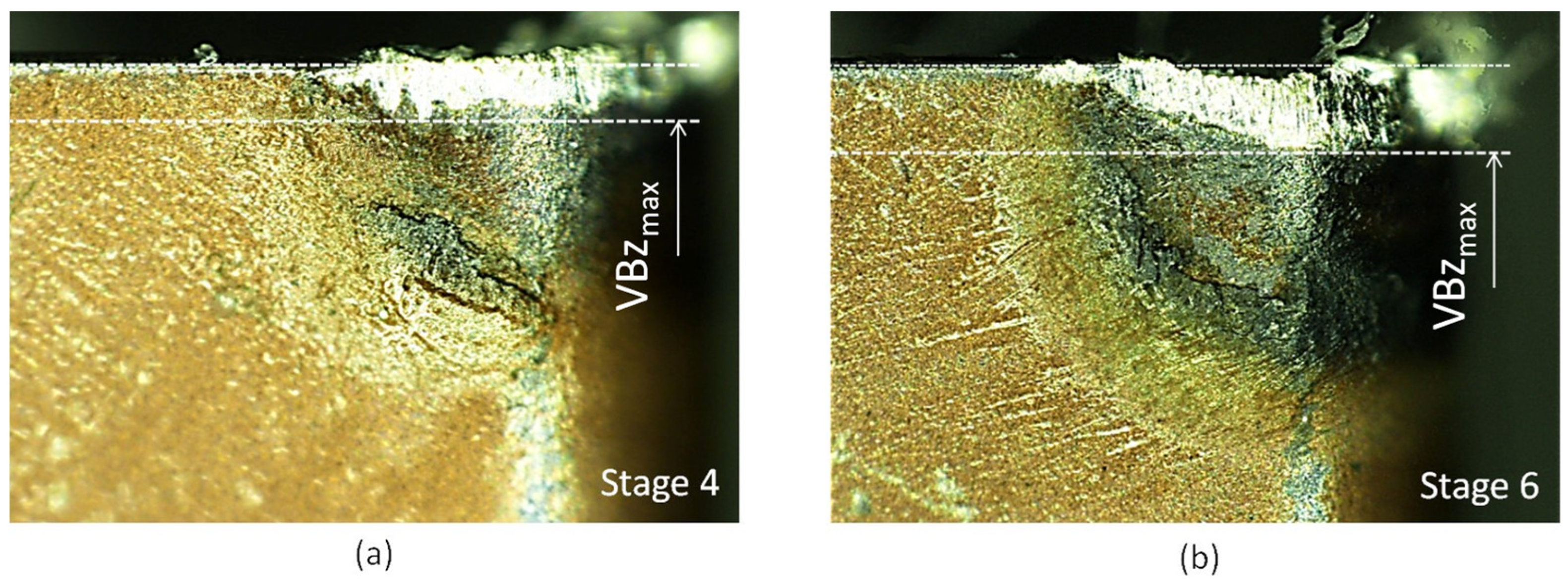
- The flank wear profile was shown to be the maximum on the tool nose midway between the major and minor flank edges.
- o
- The measured radial force (Fr) on the tool increased at a much faster rate than the main cutting (Fc) and feed (Fa) forces, confirming a higher sensitivity to the flank wear. Moreover, the nonlinear trend in the flank wear before VBzmax stabilised correlated well with Fr.
- o
- The measured wear rate results were unable to show dependency on the bar hardness, which was attributed to the low hardness range of the bar stock from 339 to 344 HB, which was sourced from a single batch.
- o
- Although the aged and unaged CFs were tested on the same bar piece, there was high variability in the difference in the flank wear between the aged and unaged CFs. Nevertheless, there was confidence that the flank wear for the aged CF suggested reduced performance in a qualitative way. Consequently, the wear results obtained from the five different bars for the aged CF were grouped at each measurement stage, and similarly for the unaged CF, enabling a quantitative statistical comparison of the wear results at each stage.
- o
- Irregular saw tooth features on a chip form obtained from the aged CF on reaching VBz0.2 could be attributed to vibration. Feathering along one edge was also visible for the aged CF on reaching VBz0.2 and could be attributed to the reduced lubricity of the aged CF.
- o
- The flank wear on the turning tool which often appears to be tilted slightly inwards was explained by the arc of contact that develops between the bar diameter and the flank wear on the tool. More material is lost through the wear at the top of the flank than at the bottom of the flank, and it was shown that the smaller the bar diameter, the greater the difference. This could explain the findings of Boud [42] who found that the tool temperature increased in turning a smaller diameter bar at the same surface-cutting speed.
- o
- Turning down the bar workpiece with multiple passes of the cutting tool at a small depth of cut could accelerate the notch wear at the leading edge of the tool as shown for the aged CF, which could be attributed to higher surface and subsurface hardness that develops on the workpiece through reduced lubricity.
Author Contributions
Funding
Data Availability Statement
Acknowledgments
Conflicts of Interest
Abbreviations
| BUE | Built-up edge |
| CE | Chip entanglement |
| CF | Cutting fluid |
| X, Y, Z | Axes of global coordinate system |
| Fc (N) | Main cutting force on Z-axis |
| Fa (N) | Axial force on X-axis |
| Fr (N) | Radial force on Y-axis |
| dc | Depth of cut (mm) |
| f | Feed rate (mm/rev) |
| Rn | Tool nose radius (mm) |
| tc | Cut time |
| V | Cutting surface speed (mm/min) |
| LE | Tool leading edge |
| TE | Tool trailing edge |
| PPM | Parts per million |
| Rb | Bar workpiece radius |
| VBz | Tool flank wear |
| VBz0.1 | Flank wear limit 0.1 mm |
| VBz0.2 | Flank wear limit 0.2 mm |
| VBz0.3 | Flank wear limit 0.3 mm |
| VBzmax | Maximum flank wear measured on tool nose |
| VBzmaxdiff | Flank wear difference [VBzmax (unaged CF) − Vbzmax (aged CF)] |
| Y3 | Loss of tool material from flank wear in the radial direction |
| (n) | Stage number to suspend job and measure flank wear |
| β | Tool tip clearance angle |
| k1,2 | Constants in equations. |
References
- Brinksmeier, E.; Meyer, D.; Huesmann-Cordes, A.G.; Herrmann, C. Metalworking fluids—Mechanisms and performance. CIRP Ann.—Manuf. Technol. 2015, 64, 605–628. [Google Scholar] [CrossRef]
- Seidel, B.; Meyer, D. Investigation of the influence of aging on the lubricity of metalworking fluids by means of design of experiment. Lubricants 2019, 7, 94. [Google Scholar] [CrossRef]
- Seidel, B.; Meyer, D. Influence of artificial aging on the lubricating ability of water miscible metalworking fluids. Prod. Eng. 2019, 13, 425–435. [Google Scholar] [CrossRef]
- Derani, M.N.; Ratnam, M.M. The use of tool flank wear and average roughness in assessing effectiveness of vegetable oils as cutting fluids during turning—A critical review. Int. J. Adv. Manuf. Technol. 2021, 112, 1841–1871. [Google Scholar] [CrossRef]
- Grzesik, W.; Niesłony, P.; Habrat, W.; Sieniawski, J.; Laskowski, P. Investigation of tool wear in the turning of Inconel 718 superalloy in terms of process performance and productivity enhancement. Tribol. Int. 2018, 118, 337–346. [Google Scholar] [CrossRef]
- Tamil Alagan, N.; Zeman, P.; Mara, V.; Beno, T.; Wretland, A. High-pressure flank cooling and chip morphology in turning Alloy 718. CIRP J. Manuf. Sci. Technol. 2021, 35, 659–674. [Google Scholar] [CrossRef]
- Saleem, M.Q.; Mehmood, A. Eco-friendly precision turning of superalloy Inconel 718 using MQL based vegetable oils: Tool wear and surface integrity evaluation. J. Manuf. Process. 2022, 73, 112–127. [Google Scholar] [CrossRef]
- Cutting Oil-Water Soluble Cutting Oil Manufacturer from Mumbai. Available online: https://www.dnrcorporation.in/cutting-oil.html (accessed on 25 August 2023).
- Kavita, K.; Singh, V.K.; Mishra, A.; Jha, B. Characterisation and anti-biofilm activity of extracellular polymeric substances from Oceanobacillus iheyensis. Carbohydr. Polym. 2014, 101, 29–35. [Google Scholar] [CrossRef]
- Rabenstein, A.; Koch, T.; Remesch, M.; Brinksmeier, E.; Kuever, J. Microbial degradation of water miscible metal working fluids. Int. Biodeterior. Biodegrad. 2009, 63, 1023–1029. [Google Scholar] [CrossRef]
- Sivalingam, V.; Zhao, Y.; Thulasiram, R.; Sun, J. Machining Behaviour, surface integrity and tool wear analysis in environment friendly turning of Inconel 718 alloy. Measurement 2021, 174, 109028. [Google Scholar] [CrossRef]
- Koch, T.; Passman, F.; Rabenstein, A. Comparative study of microbiological monitoring of water-miscible metalworking fluids. Int. Biodeterior. Biodegrad. 2015, 98, 19–25. [Google Scholar] [CrossRef]
- Bulletin, T. Background on Bacteria and Fungus in Metalworking Fluids; Perrysburg, OH, USA. 2006. Available online: https://www.masterfluids.com/na/en-us/technical-information/technical-bulletins.php (accessed on 17 September 2023).
- Institute of Advanced Manufacturing Sciences. Pollution Prevention Guide to Using Metal Removal Fluids in Machining Operations; Institute of Advanced Manufacturing Sciences: Cincinnati, OH, USA, 1995. [Google Scholar]
- Rakesh, M.; Datta, S.; Sankar, S. ScienceDirect Effects of Depth of Cut during Machining of Inconel 718 using Uncoated WC Tool. Mater. Today Proc. 2019, 18, 3667–3675. [Google Scholar] [CrossRef]
- Darshan, C.; Jain, S.; Dogra, M.; Gupta, M.K.; Mia, M.; Haque, R. Correction to: Influence of dry and solid lubricant-assisted MQL cooling conditions on the machinability of Inconel 718 alloy with textured tool. Int. J. Adv. Manuf. Technol. 2019, 105, 1835–1849, Erratum in Int. J. Adv. Manuf. Technol. 2019, 105, 1851. [Google Scholar] [CrossRef]
- Mahadevan, S.; Nalawade, S.; Singh, J.B.; Verma, A.; Paul, B.; Ramaswamy, K. Evolution of δ phase microstructure in alloy 718. In Proceedings of the 7th International Symposium on Superalloy, Pittsburgh, PA, USA, 10–13 October 2010; Volume 718, pp. 737–750. [Google Scholar]
- Kaynak, Y. Evaluation of machining performance in cryogenic machining of Inconel 718 and comparison with dry and MQL machining. Int. J. Adv. Manuf. Technol. 2014, 72, 919–933. [Google Scholar] [CrossRef]
- Cantero, J.L.; Díaz-Álvarez, J.; Miguélez, M.H.; Marín, N.C. Analysis of tool wear patterns in finishing turning of Inconel 718. Wear 2013, 297, 885–894. [Google Scholar] [CrossRef]
- Criado, V.; Díaz-Álvarez, J.; Cantero, J.L.; Miguélez, M.H. Study of the performance of PCBN and carbide tools in finishing machining of Inconel 718 with cutting fluid at conventional pressures. Procedia CIRP 2018, 77, 634–637. [Google Scholar] [CrossRef]
- Sharman, A.R.C.; Hughes, J.I.; Ridgway, K. An analysis of the residual stresses generated in Inconel 718 TM when turning. Mater. Process. Technol. 2006, 173, 359–367. [Google Scholar] [CrossRef]
- Rahman, M.; Teo, T.T.; Ridge, K. The Machinability of Incone1 718. J. Mater. Process. Technol. 1997, 36, 199–204. [Google Scholar] [CrossRef]
- Ostrowicki, N.; Kaim, A.; Gross, D.; Hanenkamp, N. Effect of various cooling lubricant strategies on turning Inconel 718 with different cutting materials. Procedia CIRP 2021, 101, 350–353. [Google Scholar] [CrossRef]
- Thrinadh, J.; Mohapatra, A.; Datta, S.; Masanta, M. Machining behavior of Inconel 718 superalloy: Effects of cutting speed and depth of cut. Mater. Today Proc. 2019, 26, 200–208. [Google Scholar] [CrossRef]
- Kaynak, Y.; Tascioglu, E. Finish machining-induced surface roughness, microhardness and XRD analysis of selective laser melted Inconel 718 alloy. Procedia CIRP 2018, 71, 500–504. [Google Scholar] [CrossRef]
- Yao, C.; Zhou, Z.; Zhang, J.; Wu, D.; Tan, L. Experimental study on cutting force of face-turning Inconel 718 with ceramic tools and carbide tools. Adv. Mech. Eng. 2017, 9, 1–9. [Google Scholar] [CrossRef]
- Madariaga, A.; Kortabarria, A.; Hormaetxe, E.; Garay, A.; Arrazola, P.J. Influence of tool wear on residual stresses when turning Inconel 718. Procedia CIRP 2016, 45, 267–270. [Google Scholar] [CrossRef]
- Wood, P.; Boud, F.; Carter, W.; Varasteh, H.; Gunputh, U.; Pawlik, M.; Clementson, J.; Lu, Y.; Hossain, S.; Broderick, M.; et al. On the lubricity and comparative life cycle of biobased synthetic and mineral oil emulsions in machining Titanium Ti-6Al-4V at low cutting speed Sensitivity: Internal. J. Manuf. Mater. Process. 2022, 6, 154. [Google Scholar] [CrossRef]
- Gong, L.; Bertolini, R.; Ghiotti, A.; He, N.; Bruschi, S. Sustainable turning of Inconel 718 nickel alloy using MQL strategy based on graphene nanofluids. Int. J. Adv. Manuf. Technol. 2020, 108, 3159–3174. [Google Scholar] [CrossRef]
- Teo, J.J.; Olugu, E.U.; Yeap, S.P.; Abdelrhman, A.M.; Aja, O.C. Turning of Inconel 718 using Nano-Particle based vegetable oils. Mater. Today Proc. 2020, 48, 866–870. [Google Scholar] [CrossRef]
- Sen, B.; Mia, M.; Mandal, U.K.; Mondal, S.P. Synergistic effect of silica and pure palm oil on the machining performances of Inconel 690: A study for promoting minimum quantity nano doped-green lubricants. J. Clean. Prod. 2020, 258, 120755. [Google Scholar] [CrossRef]
- Kazeem, R.A.; Fadare, D.A.; Ikumapayi, O.M.; Adediran, A.A.; Aliyu, S.J.; Akinlabi, S.A.; Jen, T.C.; Akinlabi, E.T. Advances in the Application of Vegetable-Oil-Based Cutting Fluids to Sustainable Machining Operations—A Review. Lubricants 2022, 10, 69. [Google Scholar] [CrossRef]
- ISO 6506-1:2005; Metallic materials—Brinell hardness test—Part 1: Test method. Available online: https://www.iso.org/standard/37739.html (accessed on 5 July 2023).
- ASTM E23-18; Standard Test Methods for Notched Bar Impact Testing of Metallic Materials. Available online: https://www.astm.org/e0023-18.html (accessed on 5 July 2023).
- ISO 3685:1993; Tool-life testing with single-point turning tools. Available online: https://www.iso.org/standard/9151.html (accessed on 5 July 2023).
- Altintas, Y. Manufacturing Automation, 2nd ed.; Cambridge University Press: Vancouver, BC, Canada, 2012; ISBN 9781107001480. [Google Scholar]
- Yeo, C.Y.; Tam, S.C.; Jana, S.; Lau, M.W. A technical review of the laser drilling of aerospace materials. J. Mater. Process. Technol. 1994, 42, 15–49. [Google Scholar] [CrossRef]
- Nakayama, K.; Arai, M. Comprehensive Chip Form Classification Based on the Cutting Mechanism. CIRP Ann. 1992, 41, 71–74. [Google Scholar] [CrossRef]
- Colwell, L.V. Predicting the Angle of Chip Flow for Single-Point Cutting Tools. ASME-J. Fluids Eng. 1954, 76, 199–203. [Google Scholar] [CrossRef]
- Jayal, A.D.; Balaji, A.K. Effects of cutting fluid application on tool wear in machining: Interactions with tool-coatings and tool surface features. Wear 2009, 267, 1723–1730. [Google Scholar] [CrossRef]
- Wood, P.; Díaz-Álvarez, J.; Rusinek, A.; Gunputh, U.; Bahi, S.; Díaz-Álvarez, A.; Miguélez, M.; Lu, Y. Microstructure Effects on the Machinability of AM-Produced Superalloys. Crystals 2023, 13, 1190. [Google Scholar] [CrossRef]
- Boud, F.Ã. Bar diameter as an influencing factor on temperature in turning. Int. J. Mach. Tools Manuf. 2007, 47, 223–228. [Google Scholar] [CrossRef]
- CIMVANTAGE 31-48—Poolsünteetilise Emulsiooni Kontsentraat, 200L. Available online: https://www.venten.ee/cimvantage-31-48-poolsunteetilise-emulsiooni-kontsentraat-200l-13973.html (accessed on 25 August 2023).
- Mohan, C.B.; Gopalakrishna, K.; Mahesh Lohith, K.S.; Venkatesh, K.; Divakar, C.; Mithun, R.B.; Naveen, T.N. Coolant Lubricity and Coolant-Lube Compatibility with Regard to Slideway Behavior. J. Braz. Soc. Mech. Sci. Eng 2008, 30, 285–289. [Google Scholar] [CrossRef]
- Silliman, J.D. (Ed.) Cutting and Grinding Fluids: Selection and Application Paperback, 2nd ed.; Society Manufacturing Engineers: Southfield, MI, USA, 1992; ISBN 978-0872634237. [Google Scholar]
- Rossmoore, H. Extending Cutting Fluid Life. Manuf. Eng. 1975, 75, 27–28. [Google Scholar]
- Metalworking fluids – the complete Engineers Guide - Q8Oils. Available online: https://www.q8oils.com/metalworking/engineers-guide/ (accessed on 15 September 2023).
- Wear, T.; Include, T.; Contamination, T.; Include, T.; Chemistry, T.; Include, T. FAST Filtration Analysis Services Technology Ltd; 2017; Volume 44. [Google Scholar]
- Eppert, J. Understanding Contamination in Metalworking Fluids-Contamination Part 4. Available online: https://mwfmag.com/?q=content/contamination-part-4 (accessed on 15 September 2023).
- Byers, J.P. (Ed.) Metalworking Fluids; Maecel Dekker: New York, NY, USA, 1994; ISBN 9781498722223. [Google Scholar]


| Speed (mm/min) | Depth of Cut (mm) | Feed (mm/rev) | Tool Nose Radius (mm) | Tool Material | Lubricant Condition | Measures | |
|---|---|---|---|---|---|---|---|
| 30–70 | 1 | 0.168–0.393 | 0.8 | TiAlN PVD coated | Dry, vegetable emulsion | Tool wear, surface roughness | [7] |
| 60, 180 | 0.25 | 0.1 | 0.8 | Carbide, CBN | Emulsion, dry, cryogenic, CMQL | Tool wear, surface roughness | [23] |
| 50–100 | 0.4–1.2 | 0.1–0.2 | 0.8 | Coated carbide | Emulsion | Surface roughness | [11] |
| 45, 90 | 1 | 0.2 | Tool diameter 12 | Carbide | Emulsion | Chip form | [6] |
| 65, 84 | 0.2, 0.5 | 0.1 | 0.8 | Uncoated WC | Dry | Tool flank wear, cutting forces, chip form | [24] |
| 100 | 0.2–0.6 | 0.12 | 0.8 | Carbide | Dry | Chip form | [15] |
| 60 | 0.4 | 0.08–0.2 | - | - | Dry and cold air | Surface roughness, XRD analysis | [25] |
| 65–125 | 0.25 | 0.1 | 0.8, 1.2 | Carbide | Emulsion | Tool wear | [5] |
| 40–70 | 0.2–0.8 | 0.1–0.25 | 0.8, 1.2 | Carbide, ceramic | Emulsion | Cutting force | [26] |
| 30, 80 | 0.1, 0.5 | 0.15 | 0.4 | Carbide | Coolant | Residual stress | [27] |
| 60, 120 | 0.8 | 0.075 | 0.8 | Uncoated 890 grade carbide | Dry, MQL | Tool wear, cutting forces, surface roughness, chip | [18] |
| 50, 70 | 0.5 | 0.1 | 0.4 | Carbide | Dry | Tool wear and surface roughness | [19] |
| 50–300 | 0.25 | 0.1–0.15 | 0.4–0.8 | PCBN-Carbide | Emulsion | Forces and surface damage | [20] |
| 40–120 | 0.25 | 0.15, 0.25 | 0.4 | K10 coated and uncoated, WC substrate | Emulsion | Residual stress | [21] |
| 30–50 | 2 | 0.2–0.4 | - | Carbide | Wet | Tool life and forces | [22] |
| Yield Strength (Mpa) | Tensile Strength (Mpa) | Elongation (%) | Reduction in Area (%) | Brinell Hardness | |
|---|---|---|---|---|---|
| 862–1000 | ≥1034 | ≥20 | ≥35 | 314–360 | |
| ASTM E 23-18 (2018) [34] | 889 | 1220 | 32 | 52 | 341 1 |
| Element | C | Si | Mn | Cr | Mo | Fe | Al | Co | Cu | Ti | Ni | Nb |
|---|---|---|---|---|---|---|---|---|---|---|---|---|
| Wt % | 0.014 | 0.05 | 0.06 | 18.9 | 3.00 | 18.57 | 0.53 | 0.42 | 0.03 | 0.95 | 53.1 | 5.05 |
| Stage Number for Measurement | 1 | 2 | 3 | 4 | 5 | 6 | 7 |
|---|---|---|---|---|---|---|---|
| Accumulated cut time (min) | 1.75 | 3.4 | 4.98 | 6.48 | 11.7 | 16.5 | 19.3 |
| Number of tool passes per stage | 3 | 3 | 3 | 3 | 12 | 12 | 12 |
| Cut length per stage (mm) | 206 | 200 | 198 | 194 | 727 | 696 | 662 |
| Nominal bar diameter at start (mm) | 50.0 | 48.5 | 47.0 | 45.5 | 44.0 | 38.0 | 32.0 |
| Nominal bar diameter at finish (mm) | 48.5 | 47.0 | 45.5 | 44.0 | 38.0 | 32.0 | 26.0 |
| VBz0.1 | VBz0.2 | |||||||
|---|---|---|---|---|---|---|---|---|
| α1 | α2 | tc (min) | Goodness of Fit (R2) | α1 | α2 | tc (min) | Goodness of Fit (R2) | |
| Unaged | 51.3 | 0.0831 | 8.03 | 0.87 | 52.1 | 0.0787 | 17.1 | 0.94 |
| Aged | 52.9 | 0.0987 | 6.45 | 0.91 | 55.7 | 0.0869 | 14.7 | 0.91 |
| Absolute difference (%) | 21.8 | 15.1 | ||||||
| Bar Diameter (mm) | VBz (mm) | Y1 (mm) | Y2 (mm) | Y3 (mm) | Y2/Y3 (%) |
|---|---|---|---|---|---|
| 100 | 0.2000 | 49.9996 | 0.0004 | 0.0210 | 1.9% |
| 50 | 0.2000 | 24.9992 | 0.0008 | 0.0210 | 3.8% |
| 26 | 0.2000 | 12.9985 | 0.0015 | 0.0210 | 7.3% |
| 10 | 0.2000 | 4.9960 | 0.0040 | 0.0210 | 19.0% |
| Test | Unit | Limits | Unaged | Aged | |
|---|---|---|---|---|---|
| Contamination | FW index | Comparative | 13.2 | 13 | |
| Colour | Yellowish | Brownish | |||
| Emulsion condition | Fine dispersion | Fine dispersion | |||
| Chemistry | pH | 8.7–9.3 | 9 | 8.9 | |
| Conductivity | mS/cm | <7.0 | 4.7 | 4.6 | |
| Nitrate | mg/L | <150 | 8 | 26 | |
| Total hardness | °dH | <70 | 11 | 19 | |
| Chloride | mg/L | <150 | 57 | 84 | |
| Sulphate | mg/L | <400 | 111 | 200 | |
| Supplementary | Average droplet size | μm | <0.700 | 0.122 | 0.113 |
Disclaimer/Publisher’s Note: The statements, opinions and data contained in all publications are solely those of the individual author(s) and contributor(s) and not of MDPI and/or the editor(s). MDPI and/or the editor(s) disclaim responsibility for any injury to people or property resulting from any ideas, methods, instructions or products referred to in the content. |
© 2023 by the authors. Licensee MDPI, Basel, Switzerland. This article is an open access article distributed under the terms and conditions of the Creative Commons Attribution (CC BY) license (https://creativecommons.org/licenses/by/4.0/).
Share and Cite
Wood, P.; Mantle, A.; Boud, F.; Carter, W.; Gunputh, U.; Pawlik, M.; Lu, Y.; Díaz-Álvarez, J.; Miguélez Garrido, M.H. Long Sump Life Effects of a Naturally Aged Bio-Ester Oil Emulsion on Tool Wear in Finish Turning a Ni-Based Superalloy. Metals 2023, 13, 1610. https://doi.org/10.3390/met13091610
Wood P, Mantle A, Boud F, Carter W, Gunputh U, Pawlik M, Lu Y, Díaz-Álvarez J, Miguélez Garrido MH. Long Sump Life Effects of a Naturally Aged Bio-Ester Oil Emulsion on Tool Wear in Finish Turning a Ni-Based Superalloy. Metals. 2023; 13(9):1610. https://doi.org/10.3390/met13091610
Chicago/Turabian StyleWood, Paul, Andrew Mantle, Fathi Boud, Wayne Carter, Urvashi Gunputh, Marzena Pawlik, Yiling Lu, José Díaz-Álvarez, and María Henar Miguélez Garrido. 2023. "Long Sump Life Effects of a Naturally Aged Bio-Ester Oil Emulsion on Tool Wear in Finish Turning a Ni-Based Superalloy" Metals 13, no. 9: 1610. https://doi.org/10.3390/met13091610