
Effect of Carburizing Composite Laser-Shock Processing on Properties and Microstructure of 20CrNiMo Steel
 ,
,
Abstract
:1. Introduction
2. Materials and Methods
2.1. Experimental Materials
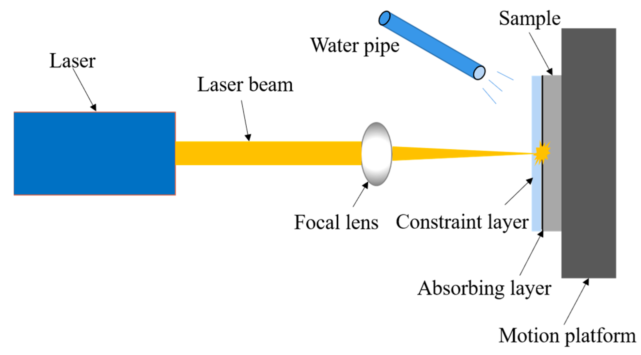
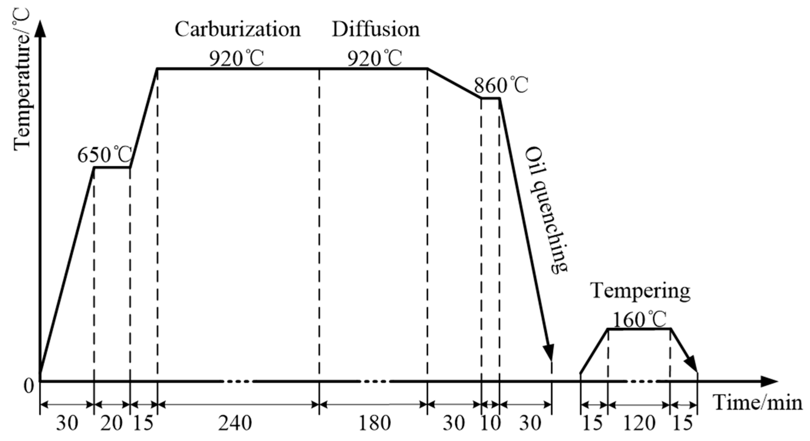
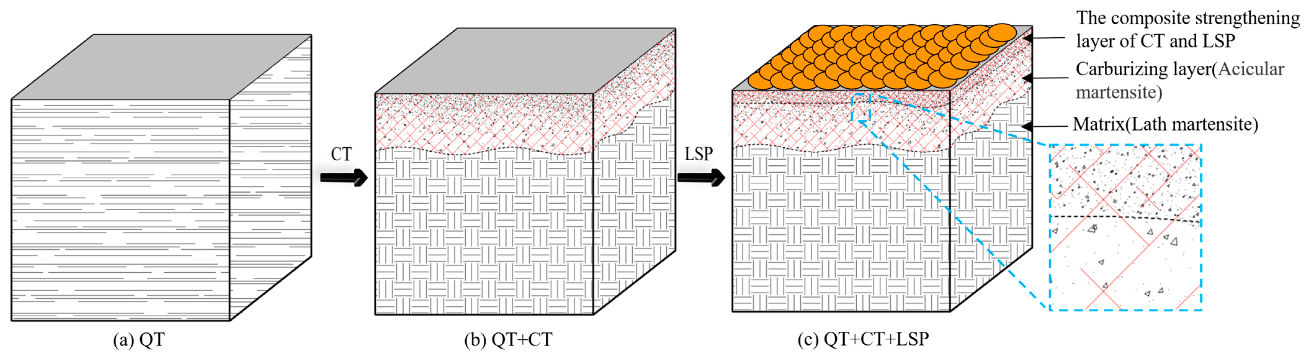
2.2. Sample Preparation
2.3. Testing and Characterization Methods
3. Results
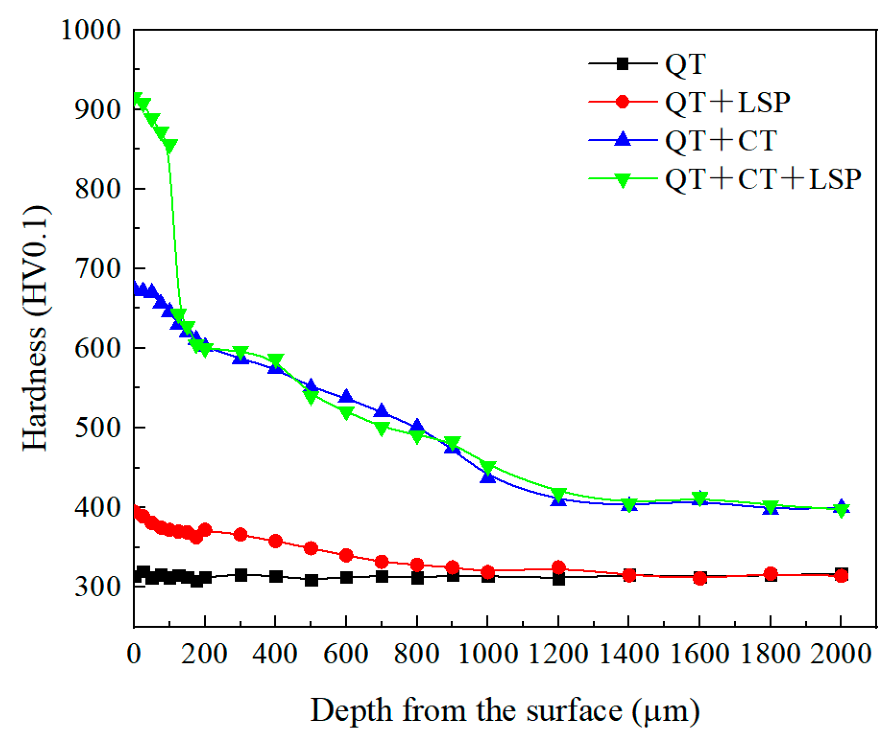
3.1. Hardness
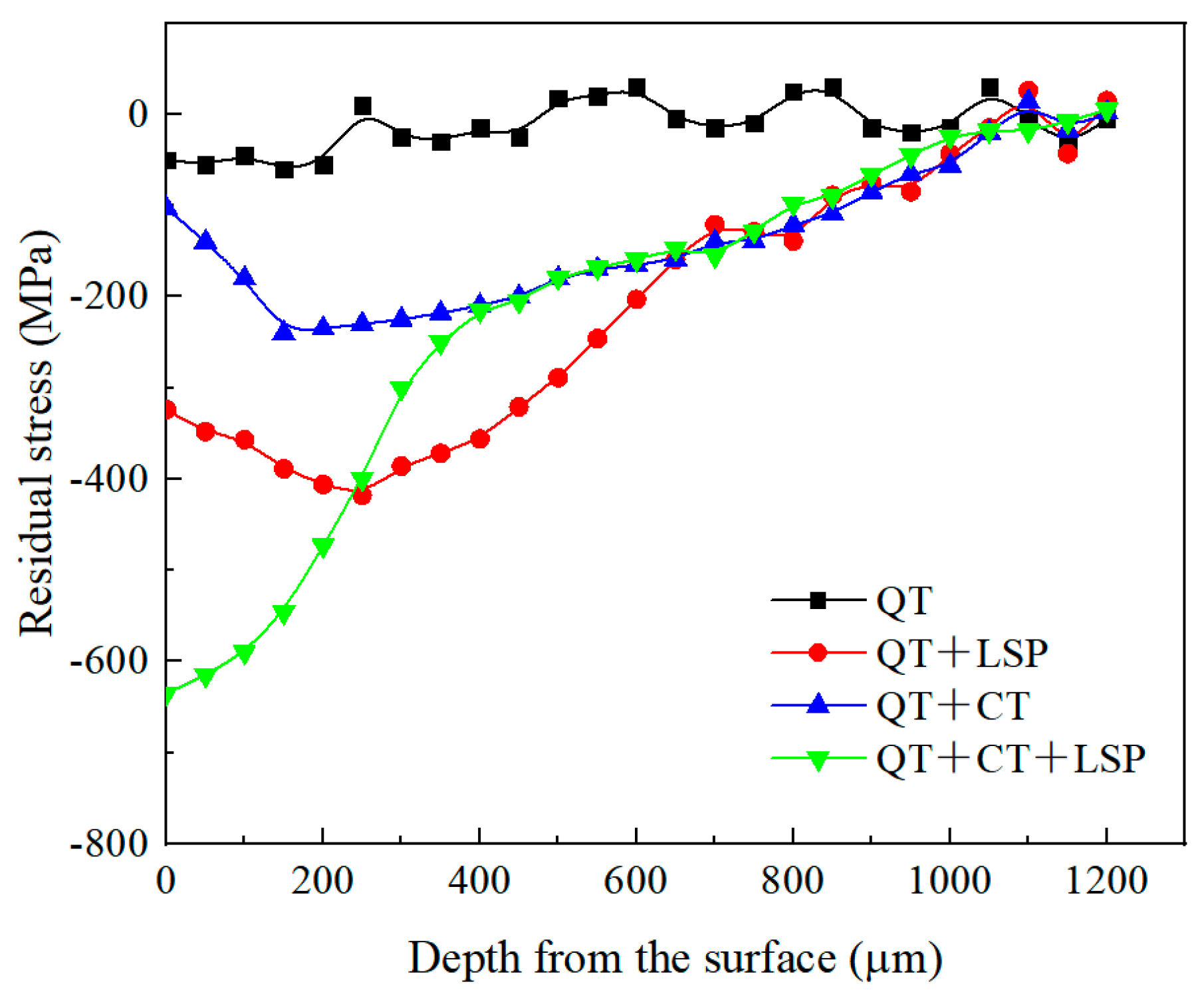
3.2. Residual Stress
3.3. Microstructure
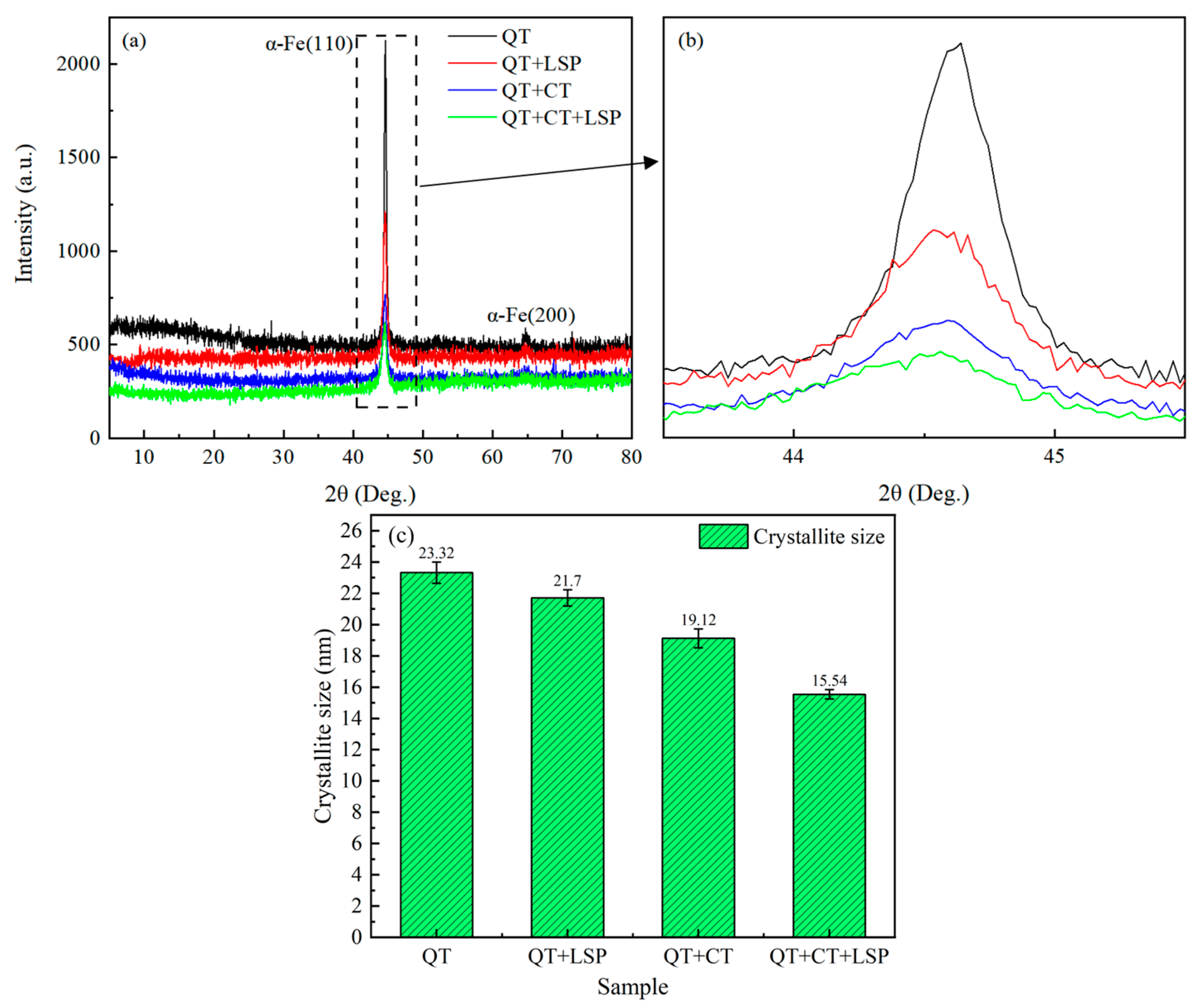
3.4. XRD Analysis
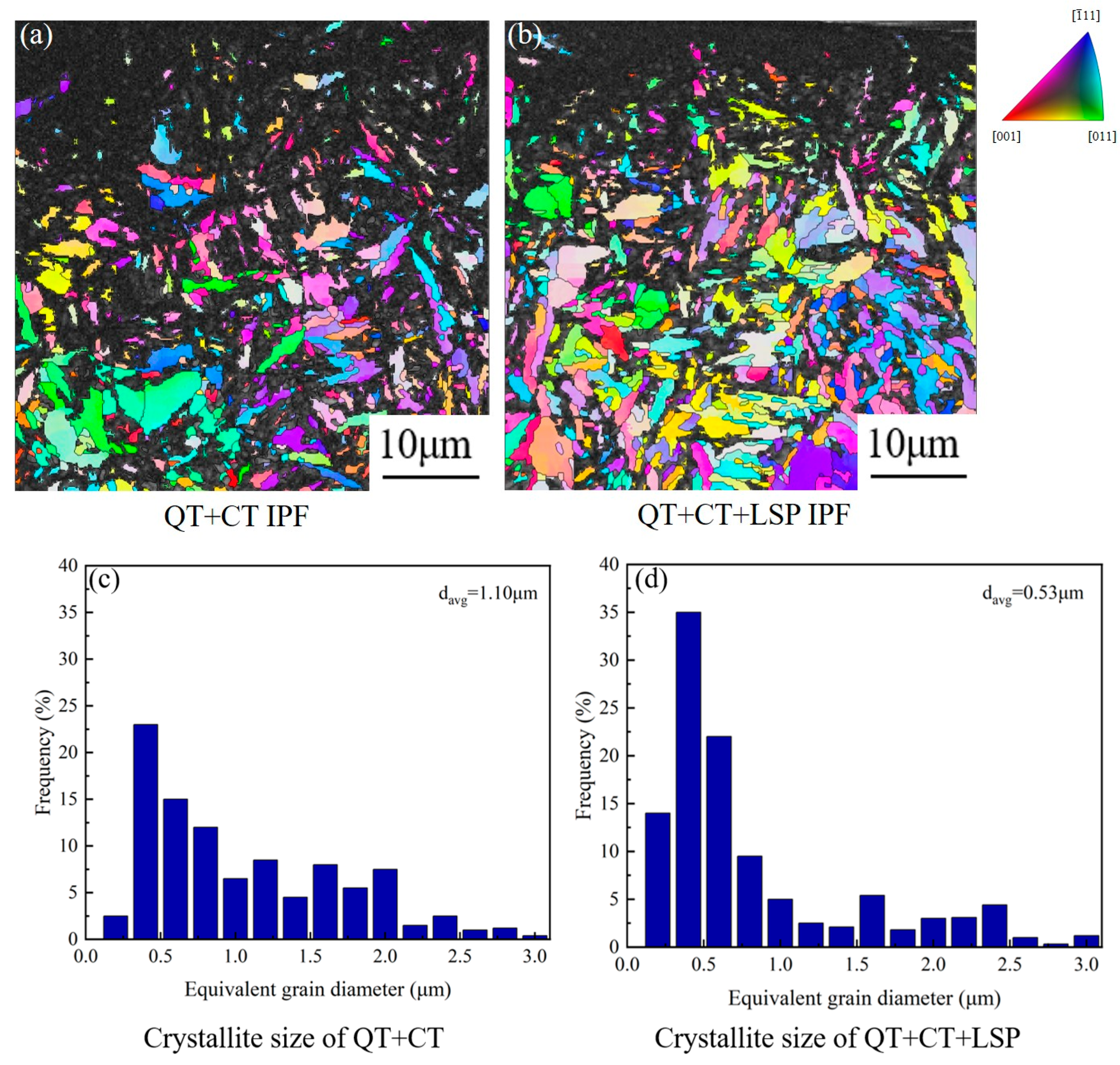
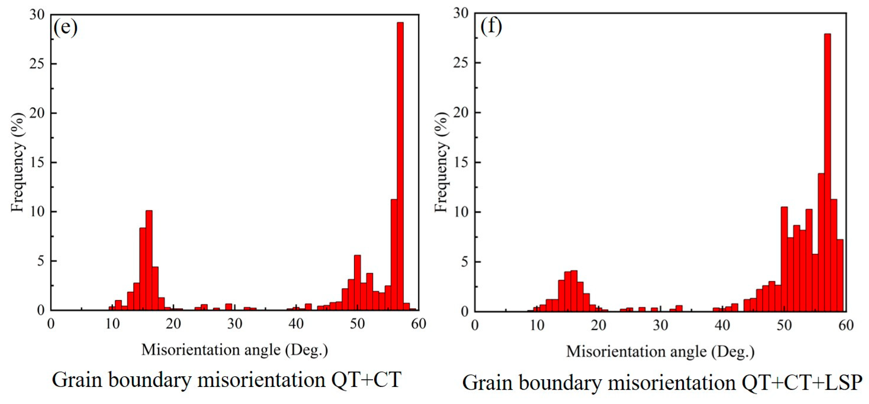
3.5. EBSD Analysis
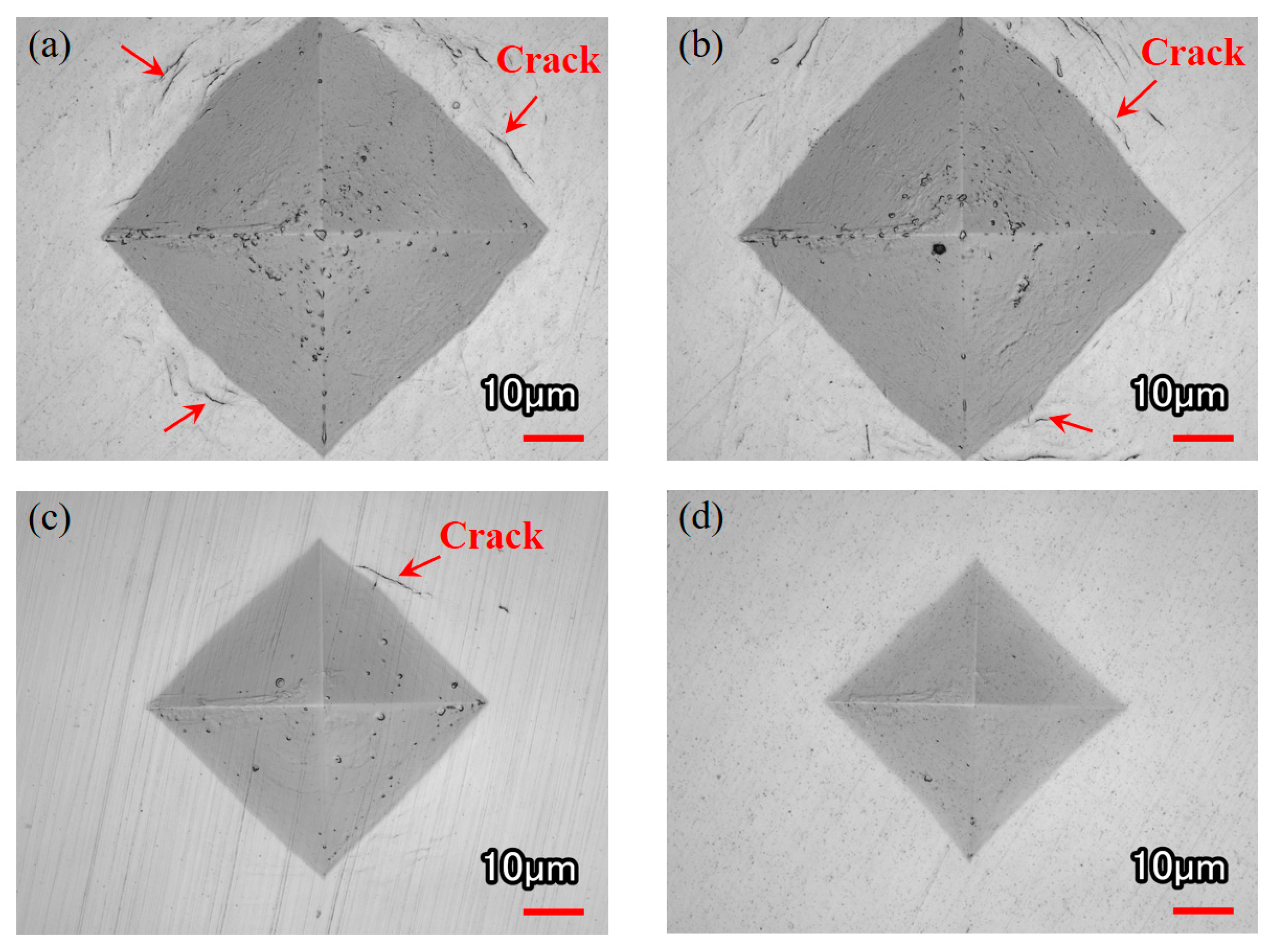
3.6. Surface Toughness Test
3.7. Characterization of Mechanical Properties
4. Discussion
5. Conclusions
Author Contributions
Funding
Data Availability Statement
Conflicts of Interest
References
- Luo, S.; Shen, Z.; Yu, Z.; Wang, W.; Zhu, M. Effect of Ce Addition on Inclusions and Grain Structure in Gear Steel 20CrNiMo. Steel Res. Int. 2020, 92, 2000394. [Google Scholar] [CrossRef]
- Feng, W.; Feng, Z.; Mao, L. Failure analysis of a secondary driving helical gear in transmission of electric vehicle. Eng. Fail. Anal. 2020, 117, 104934. [Google Scholar] [CrossRef]
- Dong, M.; Cui, X.; Zhang, Y.; Jin, G.; Yue, C.; Zhao, X.; Cai, Z.; Xu, B. Vacuum carburization of 12Cr2Ni4A low carbon alloy steel with lanthanum and cerium ion implantation. J. Rare Earths 2017, 35, 1164–1170. [Google Scholar] [CrossRef]
- Wang, J.; Qu, S.; Shao, H.; Hu, X.; Guo, B.; Li, X. Ultra-high fatigue property and fracture mechanism of modified 20CrMoH steel by gas carburizing technology combined with shot peening treatment. Int. J. Fatigue 2022, 165, 107221. [Google Scholar] [CrossRef]
- Chu, Y. The Evolution of Microstructure for Carburizing and Quenching 17CrNiMo6 Steel Forecasting and Experimentation. Coatings 2022, 12, 1102. [Google Scholar] [CrossRef]
- Xu, G.; Luo, J.; Lu, F.; Wang, G.; Liu, H.; Zhao, M. Characterization of fracture toughness for surface-modified layer of 18CrNiMo7-6 alloy steel after carburizing heat treatment by indentation method. Eng. Fract. Mech. 2022, 269, 108508. [Google Scholar] [CrossRef]
- Xiao, N.; Hui, W.; Zhang, Y.; Zhao, X.; Chen, Y.; Dong, H. High cycle fatigue behavior of a low carbon alloy steel: The influence of vacuum carburizing treatment. Eng. Fail. Anal. 2020, 109, 104215. [Google Scholar] [CrossRef]
- Qin, S.; Zhang, C.; Zhang, B.; Ma, H.; Zhao, M. Effect of carburizing process on high cycle fatigue behavior of 18CrNiMo7-6 steel. J. Mater. Res. Technol. 2022, 16, 1136–1149. [Google Scholar] [CrossRef]
- Gu, H.; Yan, P.; Jiao, L.; Chen, S.; Song, Y.; Zou, S.; Wang, X. Effect of laser shock peening on boring hole surface integrity and conformal contact fretting fatigue life of Ti-6Al-4 V alloy. Int. J. Fatigue 2023, 166, 107241. [Google Scholar] [CrossRef]
- Pan, X.; Gu, Z.; Qiu, H.; Feng, A.; Li, J. Study of the Mechanical Properties and Microstructural Response with Laser Shock Peening on 40CrMo Steel. Metals 2022, 12, 1034. [Google Scholar] [CrossRef]
- Li, W.; Chen, H.; Huang, W.; Chen, J.; Zuo, L.; Li, C.; He, J.; Ren, Y.; Zhang, S. Effect of laser shock peening on high cycle fatigue properties of aluminized AISI 321 stainless steel. Int. J. Fatigue 2021, 147, 106180. [Google Scholar] [CrossRef]
- Zhou, L.; Pan, X.; Shi, X.; Du, T.; Wang, L.; Luo, S.; He, W.; Chen, P. Research on surface integrity of Ti-6Al-4V alloy with compound treatment of laser shock peening and shot peening. Vacuum 2022, 196, 110717. [Google Scholar] [CrossRef]
- Ho, H.S.; Li, D.L.; Zhang, E.L.; Niu, P.H. Shot Peening Effects on Subsurface Layer Properties and Fatigue Performance of Case-Hardened 18CrNiMo7-6 Steel. Adv. Mater. Sci. Eng. 2018, 2018, 3795798. [Google Scholar] [CrossRef]
- Song, J.; Luo, S.; Liang, X.; Cao, Z.; Zhao, W.; Pu, C.; He, W. Rolling contact fatigue and damage characteristic of AISI 9310 steel with pre-laser shock peening treatment. Int. J. Fatigue 2022, 155, 106588. [Google Scholar] [CrossRef]
- Dannoshita, H.; Hasegawa, H.; Higuchi, S.; Matsuda, H.; Gong, W.; Kawasaki, T.; Harjo, S.; Umezawa, O. Evolution of dislocation structure determined by neutron diffraction line profile analysis during tensile deformation in quenched and tempered martensitic steels. Mater. Sci. Eng. A 2022, 854, 143795. [Google Scholar] [CrossRef]
- Chen, X.; Sun, J.; Xu, Z.; Chen, J.; Jiang, Q.; Li, Y.; Li, J.; Cheng, J. Optimization of Laser Shock Process Parameters for 40Cr Steel. Coatings 2022, 12, 1872. [Google Scholar] [CrossRef]
- Luo, S.; He, W.; Chen, K.; Nie, X.; Zhou, L.; Li, Y. Regain the fatigue strength of laser additive manufactured Ti alloy via laser shock peening. J. Alloys Compd. 2018, 750, 626–635. [Google Scholar] [CrossRef]
- Luo, X.; Dang, N.; Wang, X. The effect of laser shock peening, shot peening and their combination on the microstructure and fatigue properties of Ti-6Al-4V titanium alloy. Int. J. Fatigue 2021, 153, 106465. [Google Scholar] [CrossRef]
- Cao, J.; Cao, X.; Jiang, B.; Yuan, F.; Yao, D.; Huang, J. Microstructural evolution in the cross section of Ni-based superalloy induced by high power laser shock processing. Opt. Laser Technol. 2021, 141, 107127. [Google Scholar] [CrossRef]
- Minamizawa, K.; Arakawa, J.; Akebono, H.; Nambu, K.; Nakamura, Y.; Hayakawa, M.; Kikuchi, S. Fatigue limit estimation for carburized steels with surface compressive residual stress considering residual stress relaxation. Int. J. Fatigue 2022, 160, 106846. [Google Scholar] [CrossRef]
- Sun, Y.; Liu, W.J.; Zhang, H.W. Simulation of Residual Stress Evolution of 8Cr4Mo4V Steel Induced by Laser Shock and Its Influence on Fatigue Performance. Chin. J. Mater. Res. 2023, 1–12. Available online: http://kns.cnki.net/kcms/detail/21.1328.TG.20231017.1623.002.html (accessed on 2 December 2023).
- Lu, W.; Zhang, C.; Luan, S. Quantifying effect of overload-induced residual stress behind crack tip on fatigue crack growth. Eng. Fract. Mech. 2023, 292, 109593. [Google Scholar] [CrossRef]
- Jiang, Q.; Zhu, L.; Chen, J.; Chen, X.; Weng, J.; Xu, Z.; Zhao, Z. The Effects of Ultrasonic Impact Modification on the Surface Quality of 20CrNiMo Carburized Steel. Coatings 2023, 13, 1594. [Google Scholar] [CrossRef]
- Kanetani, K.; Mikami, T.; Ushioda, K. Effect of Retained Austenite on Sub-surface Initiated Spalling during Rolling Contact Fatigue in Carburized SAE4320 Steel. ISIJ Int. 2020, 60, 1774–1783. [Google Scholar] [CrossRef]
- Roy, S.; Sundararajan, S. The effect of heat treatment routes on the retained austenite and Tribomechanical properties of carburized AISI 8620 steel. Surf. Coat. Technol. 2016, 308, 236–243. [Google Scholar] [CrossRef]
- Yang, K.; Huang, Q.; Zhong, B.; Wang, Q.; Chen, Q.; Chen, Y.; Su, N.; Liu, H. Enhanced extra-long life fatigue resistance of a bimodal titanium alloy by laser shock peening. Int. J. Fatigue 2020, 141, 105868. [Google Scholar] [CrossRef]
- Yang, F.; Liu, P.; Zhou, L.; He, W.; Pan, X.; An, Z. Review on Anti-Fatigue Performance of Gradient Microstructures in Metallic Components by Laser Shock Peening. Metals 2023, 13, 979. [Google Scholar] [CrossRef]
- Warren, B.E. X-ray Diffraction; Courier Corporation: Chelmsford, MA, USA, 1990. [Google Scholar]
- Dhakal, B.; Swaroop, S. Effect of laser shock peening on mechanical and microstructural aspects of 6061-T6 aluminum alloy. J. Mater. Process. Technol. 2020, 282, 116640. [Google Scholar] [CrossRef]
- Karthik, D.; Yazar, K.U.; Bisht, A.; Swaroop, S.; Srivastava, C.; Suwas, S. Gradient plastic strain accommodation and nanotwinning in multi-pass laser shock peened 321 steel. Appl. Surf. Sci. 2019, 487, 426–432. [Google Scholar] [CrossRef]
- Zamharir, M.J.; Aghajani, H.; Tabrizi, A.T. Evaluation of adhesion strength of TiN layer applied on 316L substrate by electrophoretic deposition. J. Aust. Ceram. Soc. 2021, 57, 1219–1230. [Google Scholar] [CrossRef]
- Li, N.; Hong, Y.; Wu, C.L.; Xu, Q. Gaseous Nitrocarburizing and Post-quenching of Low Carbon Steel. Surf. Technol. 2018, 47, 5–16. [Google Scholar] [CrossRef]
- He, Z.; Shen, Y.; Tao, J.; Chen, H.; Zeng, X.; Huang, X.; El-Aty, A.A. Laser shock peening regulating aluminum alloy surface residual stresses for enhancing the mechanical properties: Roles of shock number and energy. Surf. Coat. Technol. 2021, 421, 127481. [Google Scholar] [CrossRef]
- Muthukumaran, G.; Rai, A.K.; Gautam, J.; Babu, P.D.; Ranganathan, K.; Bindra, K.S. A Study on Effect of Multiple Laser Shock Peening on Microstructure, Residual Stress, and Mechanical Strength of 2.5 Ni-Cr-Mo (EN25) Low-Alloy Steel. J. Mater. Eng. Perform. 2022, 32, 4361–4375. [Google Scholar] [CrossRef]
- Shu, S.; Shen, Y.; Cheng, Z.; Xiong, W.; He, Z.; Song, S.; Liu, W. Laser shock peening regulating residual stress for fatigue life extension of 30CrMnSiNi2A high-strength steel. Opt. Laser Technol. 2024, 169, 110094. [Google Scholar] [CrossRef]


| Elemental Composition | C | Si | Mn | Cr | Ni | Mo | Fe |
|---|---|---|---|---|---|---|---|
| Content | 0.21 | 0.29 | 0.75 | 0.55 | 0.5 | 0.2 | BaL. |
| Process | Laser Energy (J) | Pulse Width (ns) | Spot Diameter (mm) | Overlap Ratio |
|---|---|---|---|---|
| LSP | 6 | 20 | 3 | 50% |
Disclaimer/Publisher’s Note: The statements, opinions and data contained in all publications are solely those of the individual author(s) and contributor(s) and not of MDPI and/or the editor(s). MDPI and/or the editor(s) disclaim responsibility for any injury to people or property resulting from any ideas, methods, instructions or products referred to in the content. |
© 2023 by the authors. Licensee MDPI, Basel, Switzerland. This article is an open access article distributed under the terms and conditions of the Creative Commons Attribution (CC BY) license (https://creativecommons.org/licenses/by/4.0/).
Share and Cite
Chen, X.; Sun, J.; Li, K.; Lin, Y.; Xu, Z.; Guo, B.; Chen, J.; Jiang, Q. Effect of Carburizing Composite Laser-Shock Processing on Properties and Microstructure of 20CrNiMo Steel. Metals 2024, 14, 10. https://doi.org/10.3390/met14010010
Chen X, Sun J, Li K, Lin Y, Xu Z, Guo B, Chen J, Jiang Q. Effect of Carburizing Composite Laser-Shock Processing on Properties and Microstructure of 20CrNiMo Steel. Metals. 2024; 14(1):10. https://doi.org/10.3390/met14010010
Chicago/Turabian StyleChen, Xiuyu, Jie Sun, Kelin Li, Yuru Lin, Zhilong Xu, Bicheng Guo, Junying Chen, and Qingshan Jiang. 2024. "Effect of Carburizing Composite Laser-Shock Processing on Properties and Microstructure of 20CrNiMo Steel" Metals 14, no. 1: 10. https://doi.org/10.3390/met14010010