
Purification and Recovery of Hot-Dip Galvanizing Slag via Supergravity-Induced Cake-Mode Filtration


Abstract
1. Introduction
2. Experimental
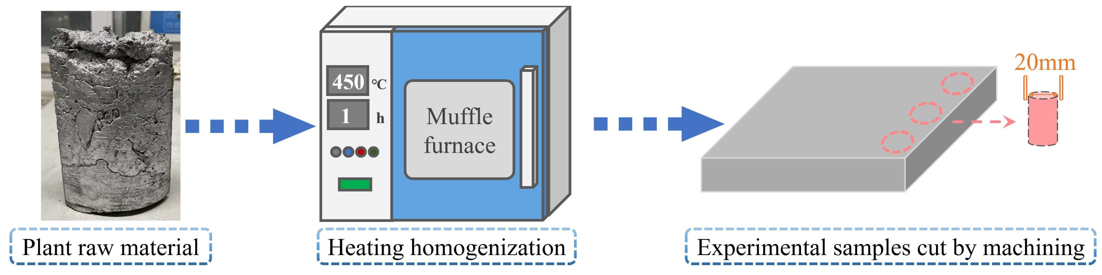
2.1. Raw Material
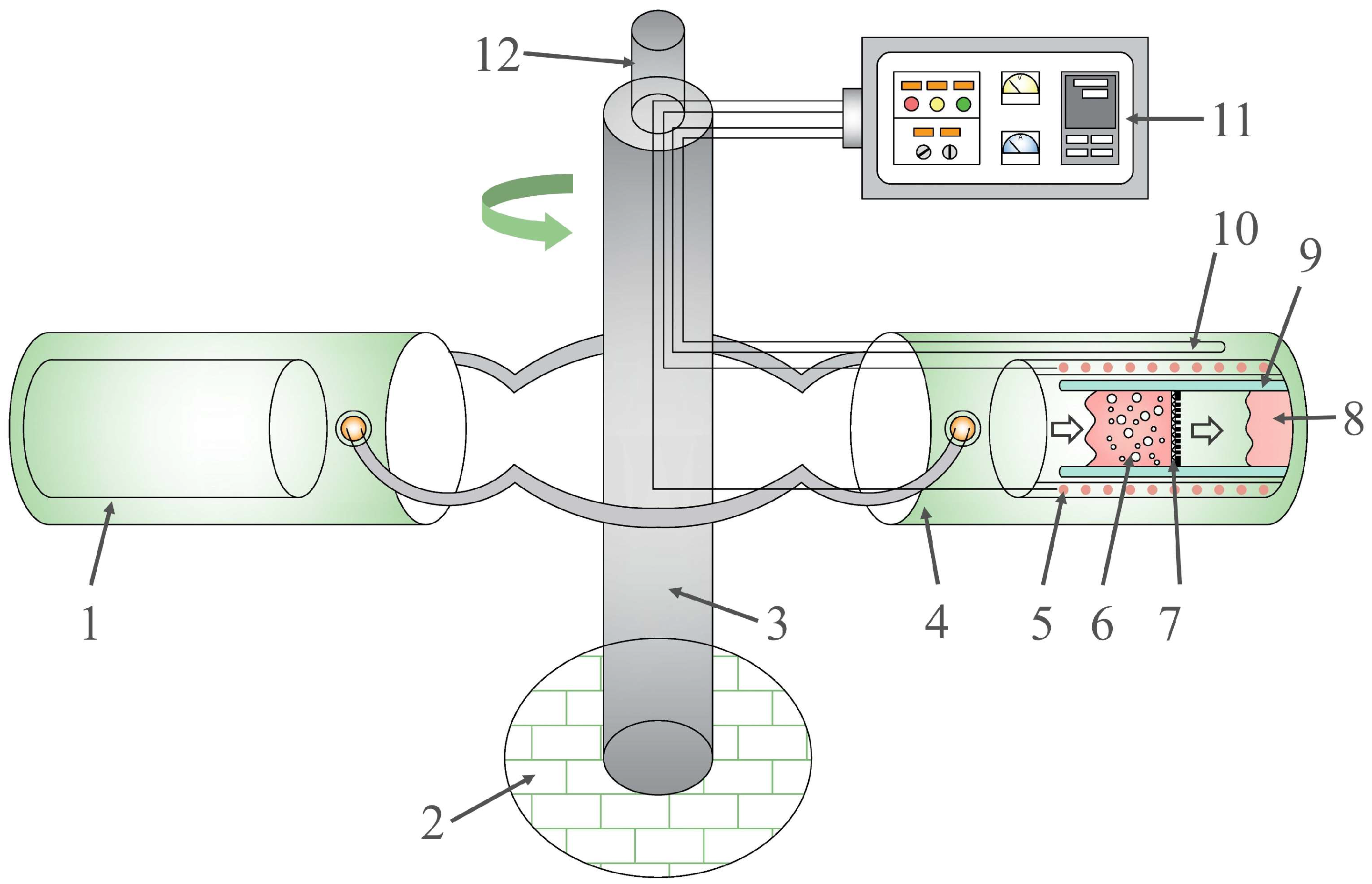
2.2. Apparatus
2.3. Experimental Procedures
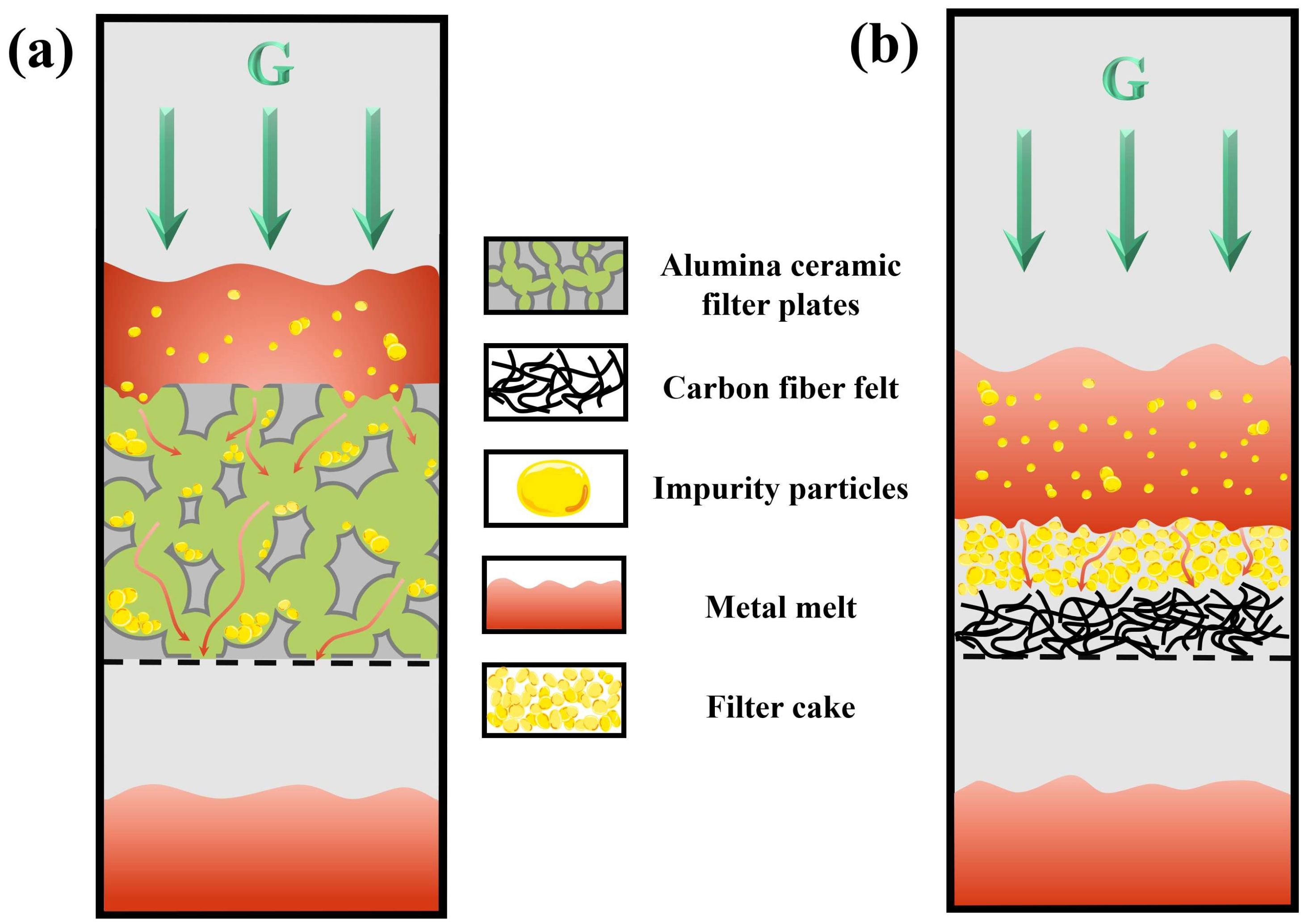
2.4. Selection of Filter Medium
2.5. Characterization
3. Results
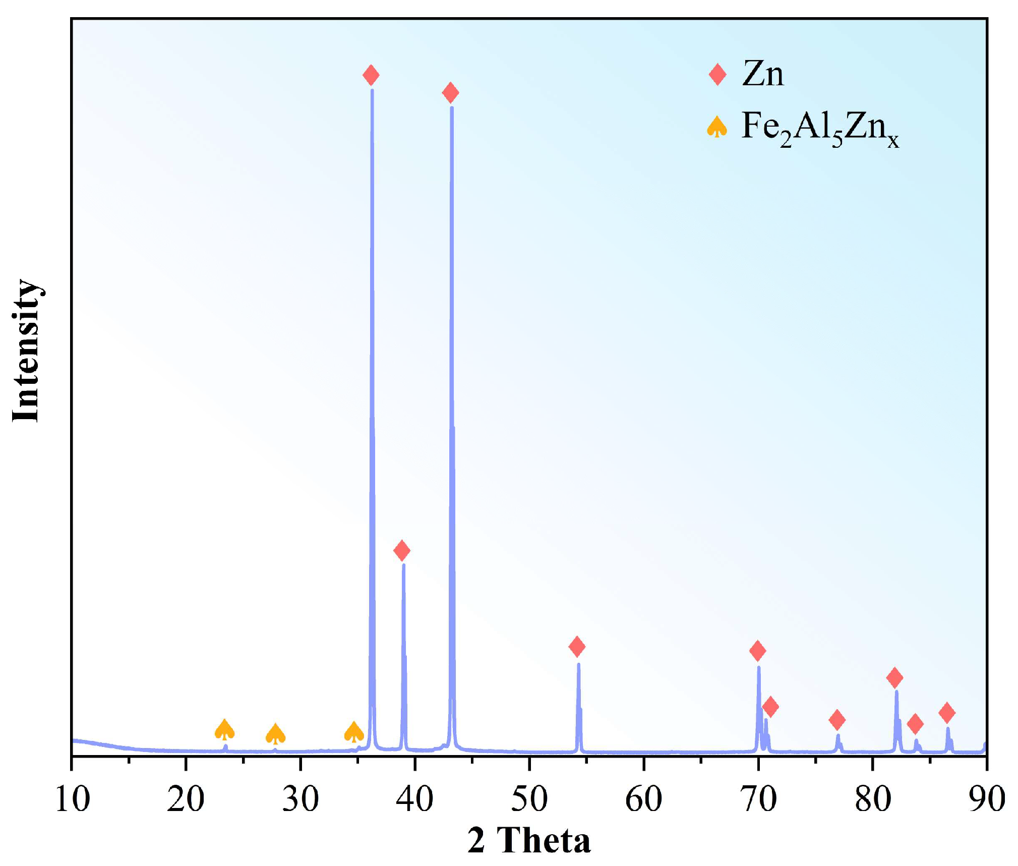
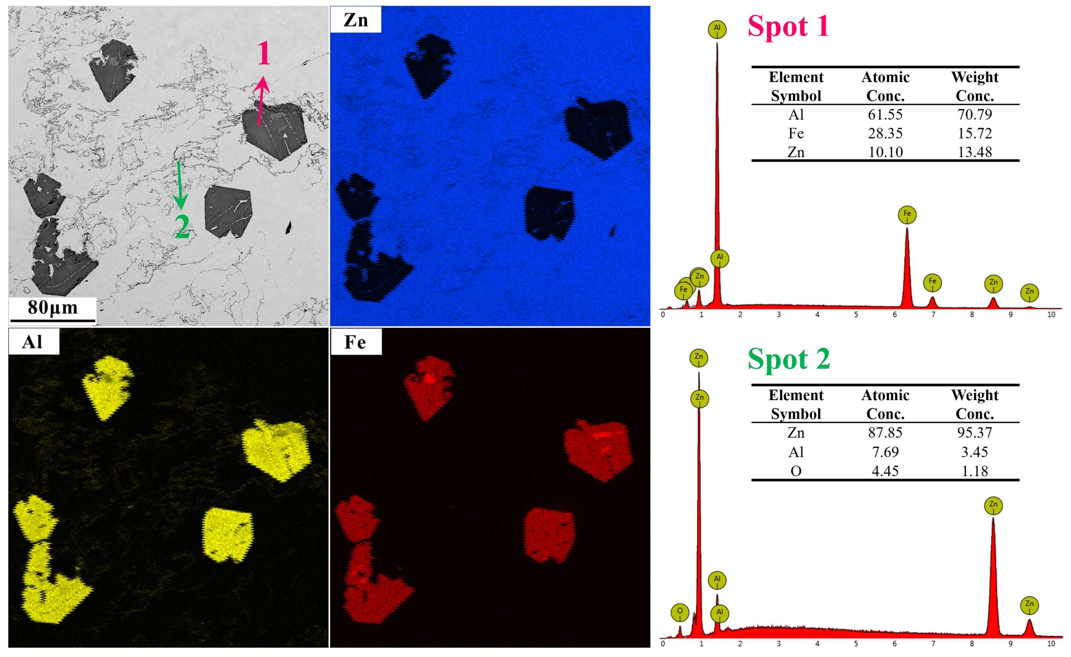
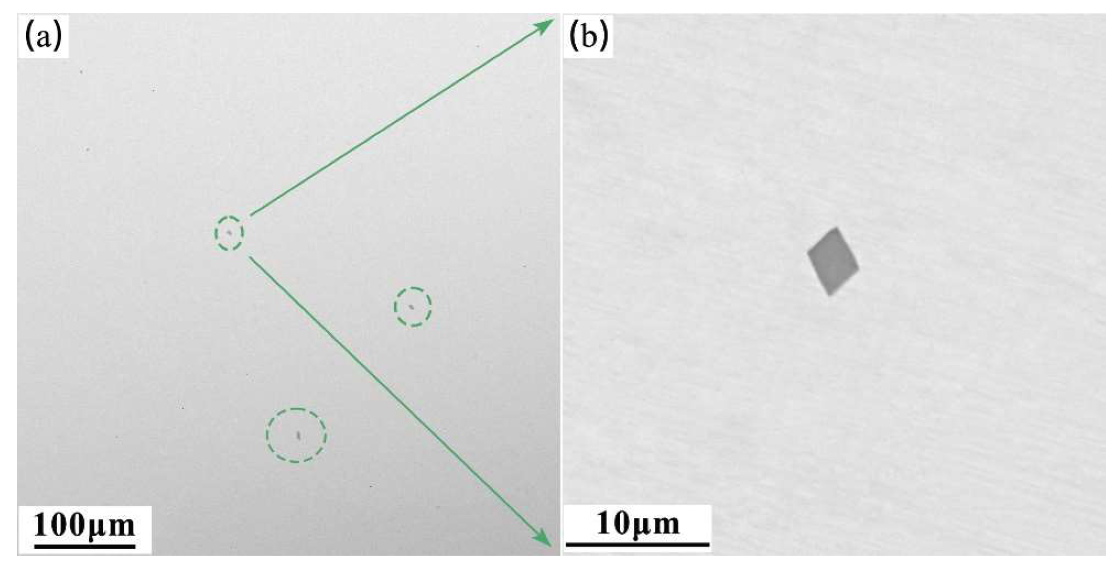
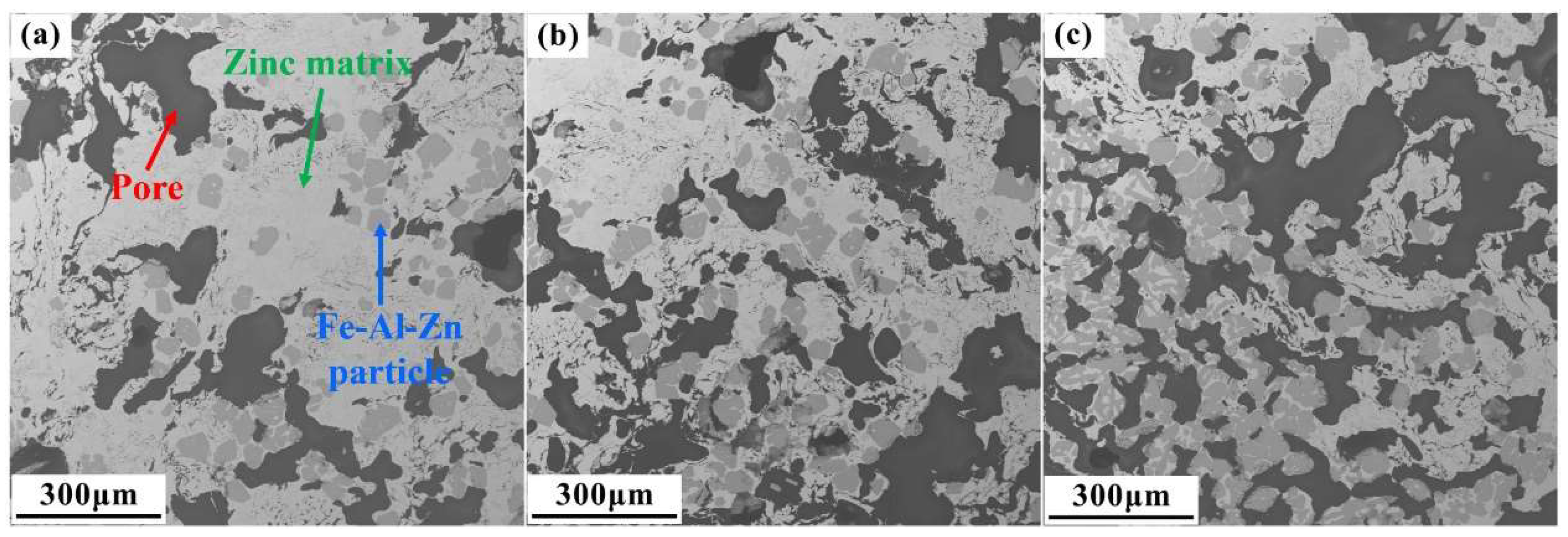
3.1. Characterization of the Raw Material
3.2. Efficiency of Centrifugal Separation
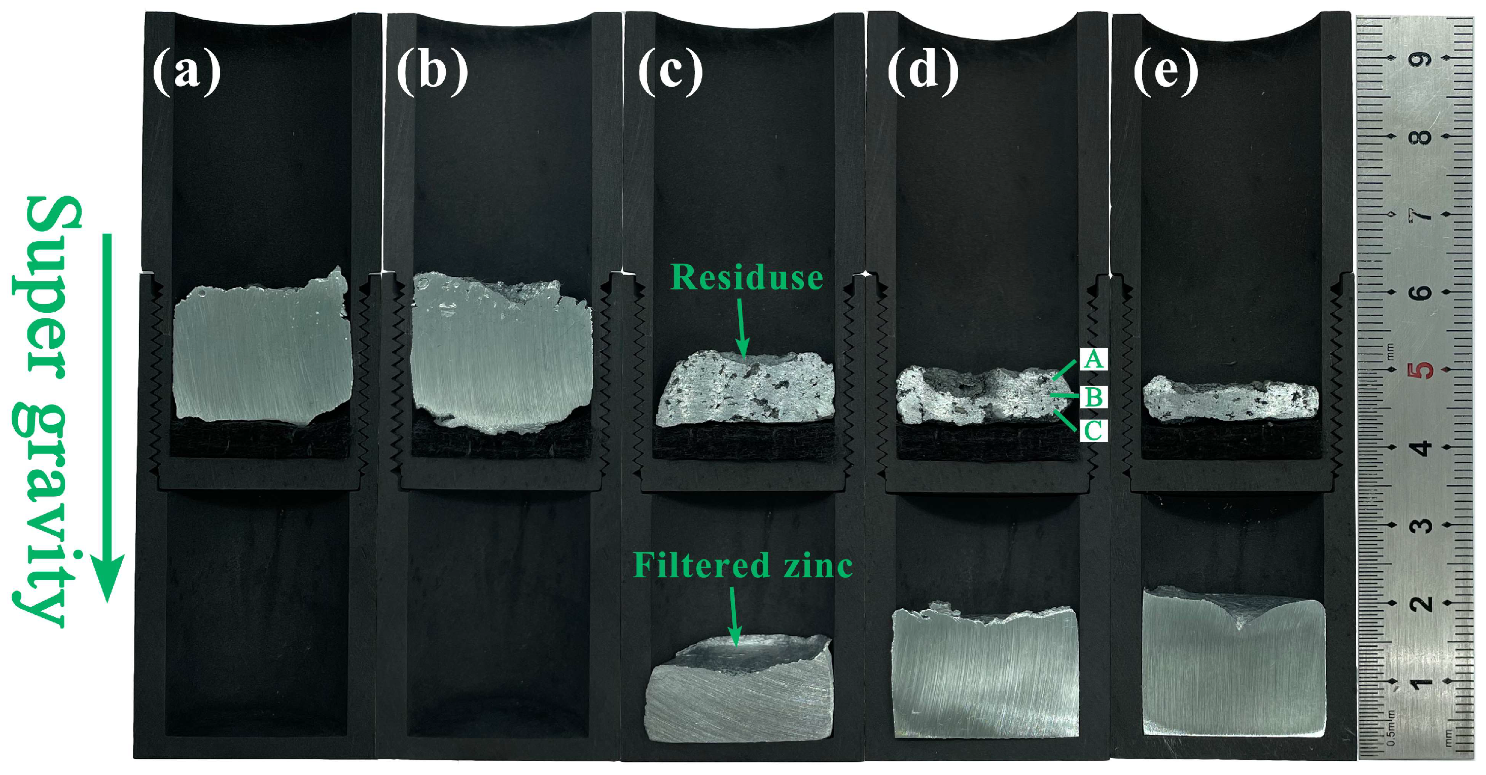
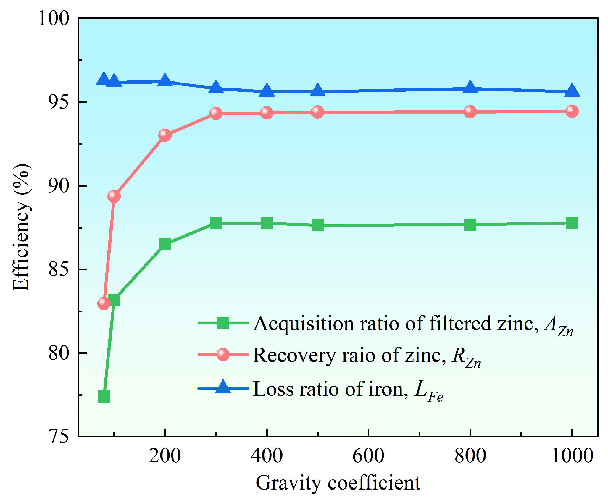
3.2.1. Effect of the Gravity Coefficient
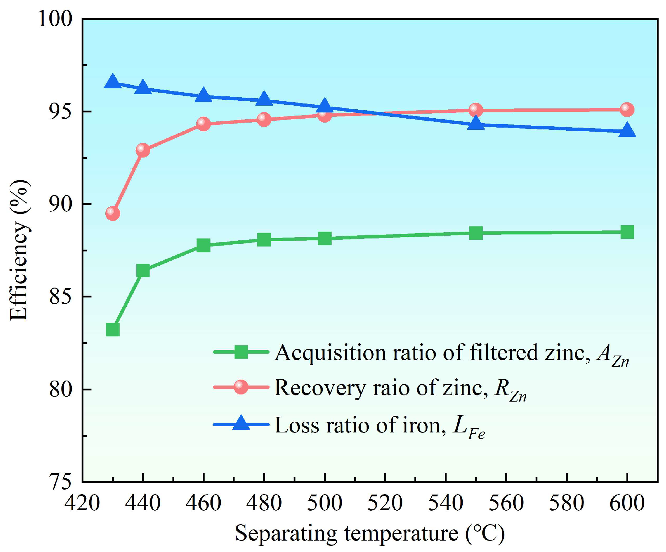
3.2.2. Effect of Separation Temperature
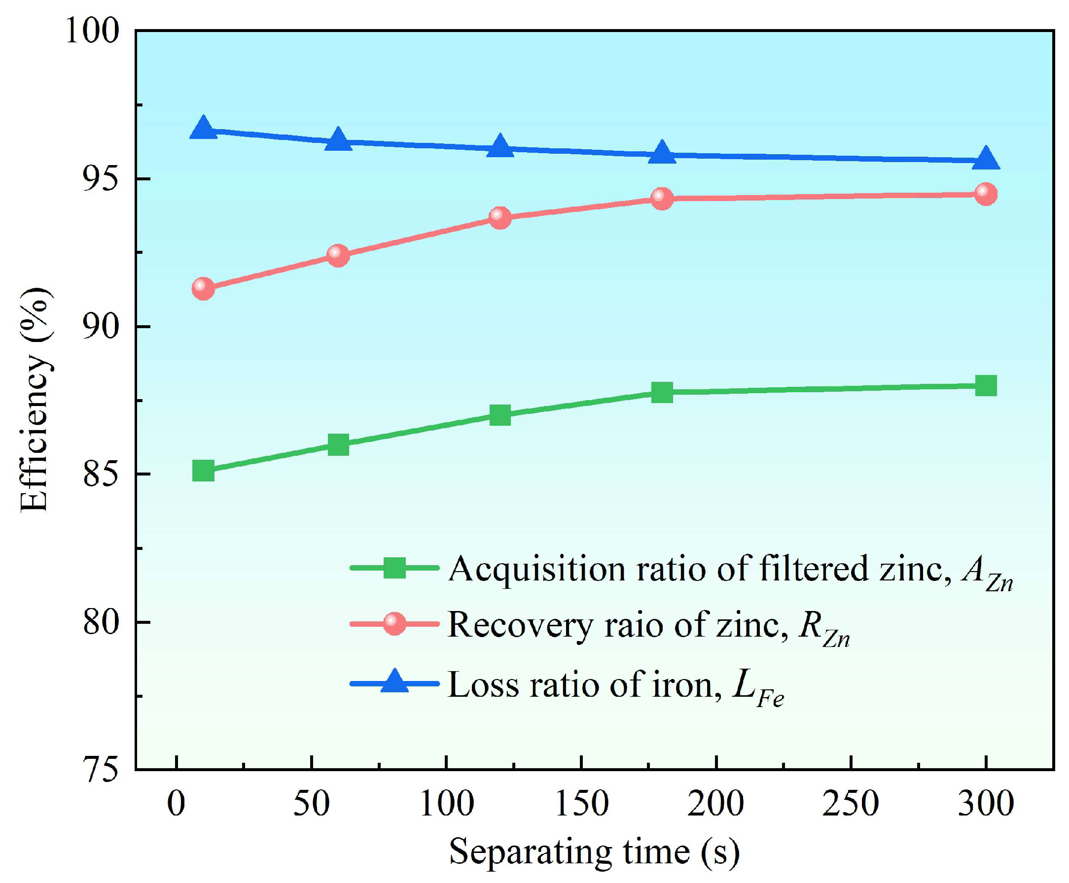
3.2.3. Effect of Separation Time
3.3. Centrifugal Separation on an Engineering Scale
4. Discussion
5. Conclusions
- (1)
- Supergravity has been verified as a very efficient and economical means of separating and recovering hot-dip galvanizing slag. The optimal conditions for laboratory conditions are G = 300, T = 460 °C and t = 120 s, under yielded the filtered zinc containing 0.022 wt% Fe and 1.097 wt% Al and separation efficiencies reached 87% for AZn, 93.67% for RZn and 96.01% for LFe.
- (2)
- With the increase in the gravity coefficient and separation temperature, the acquisition ratio AZn and RZn increased. LFe is minimally affected by the gravity coefficient, but decreases significantly as the separation temperature increases. The separation time has little effect on both the filter zinc yield, and the iron removal rate.
- (3)
- Cake-mode filtration is the most suitable filtration mechanism for hot-dip galvanizing slag with high impurity content. The filtration parameters and the relationship between filtration resistance and centrifugal pressure were analyzed.
- (4)
- Based on the separation conditions obtained from exploratory laboratory experiments, the industrial scale-up equipment was designed and fabricated, and industrial scale-up experiments were performed. It was concluded that the filtered zinc contained 0.027 wt% Fe and 1.844 wt% Al, while the values of RZn and LFe reached 85.97% and 95.47%, respectively. A fully utilized process route was also designed to maximize the benefits of the hot-dip galvanizing slag.
Author Contributions
Funding
Data Availability Statement
Conflicts of Interest
References
- Peng, S.; Xie, S.-K.; Yang, Y.-M.; Xiao, G.-Y.; Lu, J.-T.; Zhang, L.-C. Aluminum and Antimony Segregation on a Batch Hot-Dip Galvanized Zn-0.05Al-0.2Sb Coating. J. Alloys Compd. 2017, 694, 1004–1010. [Google Scholar] [CrossRef]
- Chakraborty, A.; Ghosh, R.; Sudan, M.; Mondal, A. Improvement in Hot Dip Galvanized Coating Microstructure and Properties by Pre-Metallic Deposition on Steel Surface: A Comprehensive Review. Surf. Coat. Technol. 2022, 449, 128972. [Google Scholar] [CrossRef]
- Sinha, S.; Choudhari, R.; Shekhar, S.; Mishra, D.; Sahu, K.K. Recovery of Zinc as Zinc Phosphate and By-Products from Hydrometallurgical Treatment of Hot-Dip Galvanizing (Zn-Al) Dross. Mater. Today Proc. 2021, 46, 1532–1536. [Google Scholar] [CrossRef]
- Vinter, S.; Montanes, M.T.; Bednarik, V.; Hrivnova, P. Stabilization/Solidification of Hot Dip Galvanizing Ash Using Different Binders. J. Hazard. Mater. 2016, 320, 105–113. [Google Scholar] [CrossRef]
- Kania, H.; Mendala, J.; Kozuba, J.; Saternus, M. Development of Bath Chemical Composition for Batch Hot-Dip Galvanizing—A Review. Materials 2020, 13, 4168. [Google Scholar] [CrossRef]
- Sinha, S.; Choudhari, R.; Mishra, D.; Shekhar, S.; Agrawal, A.; Sahu, K.K. Valorisation of Waste Galvanizing Dross: Emphasis on Recovery of Zinc with Zero Effluent Strategy. J. Environ. Manag. 2020, 256, 109985. [Google Scholar] [CrossRef] [PubMed]
- Ding, X.; Feng, H.; Zhao, C. Study on Zinc Slag Defects on Surface of Pure Hot Dip Galvanized Steel Sheet. J. Phys. Conf. Ser. 2022, 2390, 012022. [Google Scholar] [CrossRef]
- Gang, C.; Binbin, D.; Ling, X.; Xiaoyan, C. Research on Recognition Method of Zinc Dross in Hot Dip Galvanizing Pot Based on Image Feature. In Proceedings of the 2021 4th International Conference on Intelligent Autonomous Systems (ICoIAS), Wuhan, China, 14–16 May 2021; pp. 134–138. [Google Scholar]
- Chen, Z.; He, Y.; Zheng, W.; Wang, H.; Zhang, Y.; Li, L. Effect of Hot-Dip Galvanizing Process on Selective Oxidation and Galvanizability of Medium Manganese Steel for Automotive Application. Coatings 2020, 10, 1265. [Google Scholar] [CrossRef]
- Wang, Z.; Gao, J.; Shi, A.; Meng, L.; Guo, Z. Recovery of Zinc from Galvanizing Dross by a Method of Super-Gravity Separation. J. Alloys Compd. 2018, 735, 1997–2006. [Google Scholar] [CrossRef]
- Lobato, N.C.C.; Villegas, E.A.; Mansur, M.B. Management of Solid Wastes from Steelmaking and Galvanizing Processes: A Brief Review. Resour. Conserv. Recycl. 2015, 102, 49–57. [Google Scholar] [CrossRef]
- Bai, L.; Yue, C.F.; Li, D.J. Application Research of Slag-Removing Robot for Zinc Pot on Hot-Dip Galvanizing Line. J. Phys. Conf. Ser. 2019, 1314, 012114. [Google Scholar] [CrossRef]
- Kaya, M.; Hussaini, S.; Kursunoglu, S. Critical Review on Secondary Zinc Resources and Their Recycling Technologies. Hydrometallurgy 2020, 195, 105362. [Google Scholar] [CrossRef]
- Owais, A.; Gepreel, M.A.H.; Ahmed, E. Production of Electrolytic Zinc Powder from Zinc Anode Casing of Spent Dry Cell Batteries. Hydrometallurgy 2015, 157, 60–71. [Google Scholar] [CrossRef]
- Ren, X.; Wei, Q.; Hu, S.; Wei, S. The Recovery of Zinc from Hot Galvanizing Slag in an Anion-Exchange Membrane Electrolysis Reactor. J. Hazard. Mater. 2010, 181, 908–915. [Google Scholar] [CrossRef] [PubMed]
- Ali, S.T.; Srinivas Rao, K.; Laxman, C.; Munirathnam, N.R.; Prakash, T.L. Preparation of High Pure Zinc for Electronic Applications Using Selective Evaporation under Vacuum. Sep. Purif. Technol. 2012, 85, 178–182. [Google Scholar] [CrossRef]
- Gopala, A.; Kipphardt, H.; Matschat, R.; Panne, U. Process Methodology for the Small Scale Production of m6N5 Purity Zinc Using a Resistance Heated Vacuum Distillation System. Mater. Chem. Phys. 2010, 122, 151–155. [Google Scholar] [CrossRef]
- Kamimura, G.; Matsuura, H. Separation of ZnCl2 from Less-Volatile Chlorides by Vacuum Distillation. Metall. Mater. Trans. B 2020, 51, 1395–1405. [Google Scholar] [CrossRef]
- Ma, A.; Zheng, X.; Li, S.; Wang, Y.; Zhu, S. Zinc Recovery from Metallurgical Slag and Dust by Coordination Leaching in NH3–CH3COONH4–H2O System. R. Soc. Open Sci. 2018, 5, 180660. [Google Scholar] [CrossRef]
- Vida, S.; Gilnaz, A.; Fereshteh, R.; Navid, M. A Shrinking Particle—Shrinking Core Model for Leaching of a Zinc Ore Containing Silica. Int. J. Miner. Process. 2009, 93, 79–83. [Google Scholar]
- Rudnik, E. Hydrometallurgical Recovery of Zinc from By-Products and Waste Materials of Hot-Dip Galvanizing Process. In Recycling Technologies for Secondary Zn-Pb Resources; Kaya, M., Ed.; The Minerals, Metals & Materials Series; Springer International Publishing: Cham, Switzerland, 2023; pp. 205–234. ISBN 978-3-031-14685-5. [Google Scholar]
- Mager, K.; Meurer, U.; Garcia-Egocheaga, B.; Goicoechea, N.; Rutten, J.; Saage, W.; Simonetti, F. Recovery of Zinc Oxide from Secondary Raw Materials: New Developments of the Waelz Process. In Recycling of Metals and Engineercd Materials; Stewart, D.L., Daley, J.C., Stephens, R.L., Eds.; John Wiley & Sons, Inc.: Hoboken, NJ, USA, 2013; pp. 329–344. ISBN 978-1-118-78807-3. [Google Scholar]
- Ruetten, D.; Frias, C.; Diaz, G.; Martin, D.; Sanchez, F. Processing EAF Dust through Waelz Kiln and ZINCEXTM Solvent Extraction: The Optimum Solution. In Proceedings of the European Metallurgical Conference, EMC 2011, Barcelona, Spain, 9–12 October 2011; Volume 5, pp. 1673–1688. [Google Scholar]
- Ramshaw, C. The Opportunities for Exploiting Centrifugal Fields. Heat Recovery Syst. CHP 1993, 13, 493–513. [Google Scholar] [CrossRef]
- Sun, N.; Wang, Z.; Guo, L.; Wang, L.; Guo, Z. Efficient Separation of Reinforcements and Matrix Alloy from Aluminum Matrix Composites by Supergravity Technology. J. Alloys Compd. 2020, 843, 155814. [Google Scholar] [CrossRef]
- Meng, L.; Wang, Z.; Zhong, Y.; Guo, L.; Gao, J.; Chen, K.; Cheng, H.; Guo, Z. Supergravity Separation for Recovering Metals from Waste Printed Circuit Boards. Chem. Eng. J. 2017, 326, 540–550. [Google Scholar] [CrossRef]
- Sun, N.; Wang, Z.; Li, Y.; Sun, B.; Guo, Z. A New Technology on Continuous Purification of Galvanized Zinc Liquid through Supergravity-Induced Filtration. Process Saf. Environ. Prot. 2023, 171, 1009–1021. [Google Scholar] [CrossRef]
- Sun, B.; Sun, N.; Wang, L.; Li, Y.; Guo, Z. Efficient Purification of Scrap 1060 Aluminum Alloys Contaminated with Fe and Si by Super-Gravity Separation. Process Saf. Environ. Prot. 2023, 177, 486–495. [Google Scholar] [CrossRef]
- Dybkov, V.I.; Ebrary, I. Growth Kinetics of Chemical Compound Layers; Cambridge International Science Publishing: Cambridge, UK, 1998. [Google Scholar]
- Hogness, T.R. The Surface Tensions and Densities of Liquid Mercury, Cadmium, Zinc, Lead, Tin and Bismuth. J. Am. Chem. Soc. 1921, 43, 1621–1628. [Google Scholar] [CrossRef]
- Fu, Y.; Zhang, J.C.; Wang, Y.Z.; Yu, Y.Z. Resource Preparation of Poly-Al–Zn–Fe (PAZF) Coagulant from Galvanized Aluminum Slag: Characteristics, Simultaneous Removal Efficiency and Mechanism of Nitrogen and Organic Matters. Chem. Eng. J. 2012, 203, 301–308. [Google Scholar]
- Marder, A.R. The Metallurgy of Zinc-Coated Steel. Prog. Mater. Sci. 2000, 45, 191–271. [Google Scholar] [CrossRef]
- Falke, W.L.; Schwaneke, A.E.; Nash, R.W. Surface Tension of Zinc: The Positive Temperature Coefficient. Met. Trans. B 1977, 8, 301–303. [Google Scholar] [CrossRef]
- Etris, S.; Fiorini, Y.; Lieb, K.; Moore, I.; Batik, A.; Kelley, J.; Harris, H. Contact Angle of Zinc on Some Ceramic Materials and Metals. J. Test. Eval. 1974, 2, 40. [Google Scholar] [CrossRef]
- Mortensen, A.; Cornie, J.A. On the Infiltration of Metal Matrix Composites. Met. Trans. A 1987, 18, 1160–1163. [Google Scholar] [CrossRef]


| Zn | Al | Fe |
|---|---|---|
| 91.84 | 7.68 | 0.48 |
| Top | Middle | Bottom |
|---|---|---|
| 46.83 | 42.26 | 14.67 |
| Gravity Coefficient | AZn | RZn | LFe | Chemical Composition of the Filtered Zinc (wt%) | ||
|---|---|---|---|---|---|---|
| Zn | Fe | Al | ||||
| 80 | 77.41 | 82.96 | 96.29 | 98.426 | 0.023 | 1.551 |
| 100 | 83.19 | 89.36 | 96.19 | 98.655 | 0.022 | 1.323 |
| 200 | 86.52 | 93.01 | 96.21 | 98.723 | 0.021 | 1.254 |
| 300 | 87.77 | 94.31 | 95.79 | 98.686 | 0.023 | 1.291 |
| 400 | 87.70 | 94.22 | 95.98 | 98.662 | 0.022 | 1.314 |
| 500 | 87.64 | 94.40 | 95.62 | 98.928 | 0.024 | 1.048 |
| 800 | 87.68 | 94.42 | 95.80 | 98.900 | 0.023 | 1.077 |
| 1000 | 87.78 | 94.45 | 95.61 | 98.819 | 0.024 | 1.157 |
| G = 80 | G = 300 | G = 1000 |
|---|---|---|
| 27.28 | 37.79 | 42.84 |
| Top | Middle | Bottom |
|---|---|---|
| 53.86 | 36.31 | 22.68 |
| Separation Temperature (°C) | AZn | RZn | LFe | Chemical Composition of the Filtered Zinc (wt%) | ||
|---|---|---|---|---|---|---|
| Zn | Fe | Al | ||||
| 430 | 83.22 | 89.49 | 96.53 | 98.755 | 0.020 | 1.225 |
| 440 | 86.42 | 92.90 | 96.22 | 98.723 | 0.021 | 1.256 |
| 460 | 87.77 | 94.31 | 95.79 | 98.686 | 0.023 | 1.291 |
| 480 | 88.08 | 94.56 | 95.60 | 98.602 | 0.024 | 1.374 |
| 500 | 88.15 | 94.79 | 95.23 | 98.763 | 0.026 | 1.211 |
| 550 | 88.44 | 95.06 | 94.29 | 98.718 | 0.031 | 1.251 |
| 600 | 88.49 | 95.09 | 93.92 | 98.690 | 0.033 | 1.277 |
| Position | Raw Material | 600 °C | 550 °C | 460 °C |
|---|---|---|---|---|
| Top | 46.83 | 19.84 | 11.30 | 3.5 |
| Middle | 42.26 | 14.16 | 9.19 | 3.3 |
| Bottom | 14.67 | 13.91 | 7.10 | 3.0 |
| Separation Time (s) | AZn | RZn | LFe | Chemical Composition of the Filtered Zinc (wt%) | |||
|---|---|---|---|---|---|---|---|
| Zn | Fe | Al | |||||
| 10 | 85.12 | 91.27 | 96.63 | 98.475 | 0.019 | 1.506 | |
| 60 | 86.00 | 92.39 | 96.24 | 98.664 | 0.021 | 1.315 | |
| 120 | 87.00 | 93.67 | 96.01 | 98.881 | 0.022 | 1.097 | |
| 180 | 87.77 | 94.31 | 95.79 | 98.686 | 0.023 | 1.291 | |
| 300 | 88.00 | 94.47 | 95.60 | 98.592 | 0.024 | 1.384 | |
| Gravity Coefficients | 30 | 80 | 200 | 300 | 500 | 800 | 1000 |
|---|---|---|---|---|---|---|---|
| The theoretical percentages of the residue (%) | 100 | 39 | 16 | 10 | 6 | 4 | 3 |
| The theoretical percentages of the filtered zinc (%) | 0 | 61 | 84 | 90 | 94 | 96 | 97 |
Disclaimer/Publisher’s Note: The statements, opinions and data contained in all publications are solely those of the individual author(s) and contributor(s) and not of MDPI and/or the editor(s). MDPI and/or the editor(s) disclaim responsibility for any injury to people or property resulting from any ideas, methods, instructions or products referred to in the content. |
© 2024 by the authors. Licensee MDPI, Basel, Switzerland. This article is an open access article distributed under the terms and conditions of the Creative Commons Attribution (CC BY) license (https://creativecommons.org/licenses/by/4.0/).
Share and Cite
Zhang, S.; Wang, Z.; Lan, X.; Shi, L.; Guo, Z. Purification and Recovery of Hot-Dip Galvanizing Slag via Supergravity-Induced Cake-Mode Filtration. Metals 2024, 14, 100. https://doi.org/10.3390/met14010100
Zhang S, Wang Z, Lan X, Shi L, Guo Z. Purification and Recovery of Hot-Dip Galvanizing Slag via Supergravity-Induced Cake-Mode Filtration. Metals. 2024; 14(1):100. https://doi.org/10.3390/met14010100
Chicago/Turabian StyleZhang, Shuai, Zhe Wang, Xi Lan, Lei Shi, and Zhancheng Guo. 2024. "Purification and Recovery of Hot-Dip Galvanizing Slag via Supergravity-Induced Cake-Mode Filtration" Metals 14, no. 1: 100. https://doi.org/10.3390/met14010100
APA StyleZhang, S., Wang, Z., Lan, X., Shi, L., & Guo, Z. (2024). Purification and Recovery of Hot-Dip Galvanizing Slag via Supergravity-Induced Cake-Mode Filtration. Metals, 14(1), 100. https://doi.org/10.3390/met14010100