Article

Deciphering Microstructures and Phases of Gas-Atomised Novel Al-Fe-Si-Cr-Ni Alloys

Department of Applied Science and Technology, Politecnico di Torino, Corso Duca Degli Abruzzi 24, 10129 Turin, Italy
*
Authors to whom correspondence should be addressed.
Metals 2024, 14(1), 17; https://doi.org/10.3390/met14010017
Submission received: 17 November 2023 / Revised: 12 December 2023 / Accepted: 20 December 2023 / Published: 22 December 2023

Abstract

:
Rapid solidification techniques, such as gas atomisation, have been widely implemented in metallic alloys/composites to increase solid solubility, avoid or mitigate segregation phenomena, and favour metastable phase formation to enhance performance. Particularly, gas atomisation can enhance the solid solubility of low diffusion coefficient elements like Fe, Ni, Mn, Zr, and Cr in the α-Al matrix, yielding metastable phases. As a result, Al alloys exhibit excellent strength at high temperatures. In this study, the AISI 304L alloy was employed to introduce Fe, Ni, and Cr elements into the AlSi10Mg alloy through gas atomisation, resulting in the formation of two distinct hypereutectic AlFe-based alloys: AlFe9Si8Cr2Ni and AlFe18Si8Cr5Ni2. Gas-atomised alloy powders were separated into different size fractions by sieving and characterised using X-ray diffraction, differential scanning calorimetry, optical microscopy, and scanning electron microscopy. Microstructural analyses revealed dendritic patterns with distinct phases, highlighting the influence of the alloying element content on the solidification processes. Furthermore, a synergic evaluation of the XRD and EDS analysis results allowed the identification of intermetallic phases and their distribution in the two systems.

1. Introduction

Since the 1900s, Al-Si alloys have stood out among the plethora of aluminium alloys thanks to their exceptional characteristics, including low density, good mechanical and physical properties, excellent castability, weldability, and high corrosion resistance [1]. Consequently, these alloys have found extensive application in the automotive and aerospace sectors, contributing significantly to critical components such as pistons, engine blocks, cylinder heads, and wheels [2]. Despite the undeniable advantages of Al-Si alloys, the growing demand for sustainable practices and the imperative to reduce environmental impact have highlighted a critical challenge in recycling Al-Si alloys: pervasive iron contaminations [3].
The presence of iron in Al-Si alloys increases properties at high temperatures and hardness but decreases corrosion resistance, fluidity, and plastic properties [4]. As previously reported, iron content exceeding 0.5% results in the formation of brittle intermetallic phases such as the Al5FeSi (β) phase, which has an adverse impact on the mechanical properties of the alloy due to its needle-like morphology [5]. For instance, Lan et al. [6] reported that the Al5FeSi (β) phase could be refined to the Al8Fe2Si (α) phase by increasing the cooling rate and Fe/Si ratio in Al-5Fe-xSi (X = 3.5–8 wt.%) alloys. This approach effectively mitigated the deleterious impact of the Al5FeSi (β) phase and improved the alloy’s thermal performance without sacrificing mechanical properties. Notwithstanding this, Al-Fe-Si phases are always discouraged, and finding a method to recycle Al-Si alloys with Fe contamination without decreasing the mechanical properties has become a growing concern. Since a reliable and economical method for removing iron from Al-Si alloys has not been known in metallurgical practice, the literature has turned to the exploration of iron correctors such as Mn, Ni, Co, Cr, Ti, V, and Mo [7].
Based on studies conducted in the literature, among the elements that can be used to correct the detrimental effects of iron in Al-Si alloys are Cr and Ni [7]. In particular, Cr demonstrated improved resistance at room and high temperatures without excessively burdening elongation at the break by precipitating intermetallic Cr phases acting as inoculant phases [8]. In addition, Cr is an inexpensive alloying element with low diffusion coefficients in aluminium that forms a solid solution with the α-Al matrix, exploiting solid-solution strengthening [9]. On the other hand, Ni in aluminium alloys is known to stabilise mechanical properties at elevated temperatures due to the low diffusivity in aluminium [10]. In addition, the presence of Ni in Al-Si alloys enhanced the corrosion resistance, decreasing the pitting rate under a long-term corrosion process [11]. Despite evidence of the beneficial aspects of Cr and Ni as iron correctors in Al-Si compositions, their content in the alloy is less than 1.0 wt.%. [7].
Obtaining these compositions with rapid solidification processes could increase the amount of alloying elements by extending their solid solubility limits in an Al-matrix due to the high cooling rates involved [12]. Among the techniques for producing metal powders that guarantee the highest cooling rates is inert gas atomisation (IGA) [13]. During IGA, a high-speed jet of inert gas is forced through tiny nozzles to disintegrate a molten stream of the alloy. The IGA process has become one of the most promising approaches for the development of metal compositions with a high content of alloying elements. In addition, the appeal of the IGA process could also be explained by its ability to produce a nearly spherical powder with a controlled particle size distribution suitable for the feedstock material of powder-based additive manufacturing (PB-AM) technologies [14].
To the best of the authors’ knowledge, no available studies in the literature analyse the effect of high cooling rates in the IGA process on the amount of Fe, Cr, and Ni as alloying elements in Al-Si base alloys. To fill this literature gap, the present study focused on designing a novel Al-Fe-Si-Cr-Ni composition tailored for rapid solidification. In order to obtain the Al-Fe-Si-Cr-Ni compositions considering the pivotal aspect of sustainability, it was decided to start from ingots of two of the most widespread alloys for AM and conventional processes: AlSi10Mg (for Al and Si elements) and AISI 304L (for Fe, Ni, and Cr elements). In particular, these starting alloys were balanced to achieve Fe contents above and below its solubility limit in the aluminium matrix. Fe solid solubility in Al is 0.05 wt.% at thermodynamic equilibrium but can be increased up to 12.0 wt.% using rapid solidification processes [15]. For this reason, the compositions selected for the present study were AlFe9Si8Cr2Ni and AlFe18Si8Cr5Ni2. The two gas-atomised Al-Fe-Si-Cr-Ni powders were thoroughly investigated from a morphological and microstructural perspective, with attention paid to the role of the alloying element content and particle size.

2. Materials and Methods

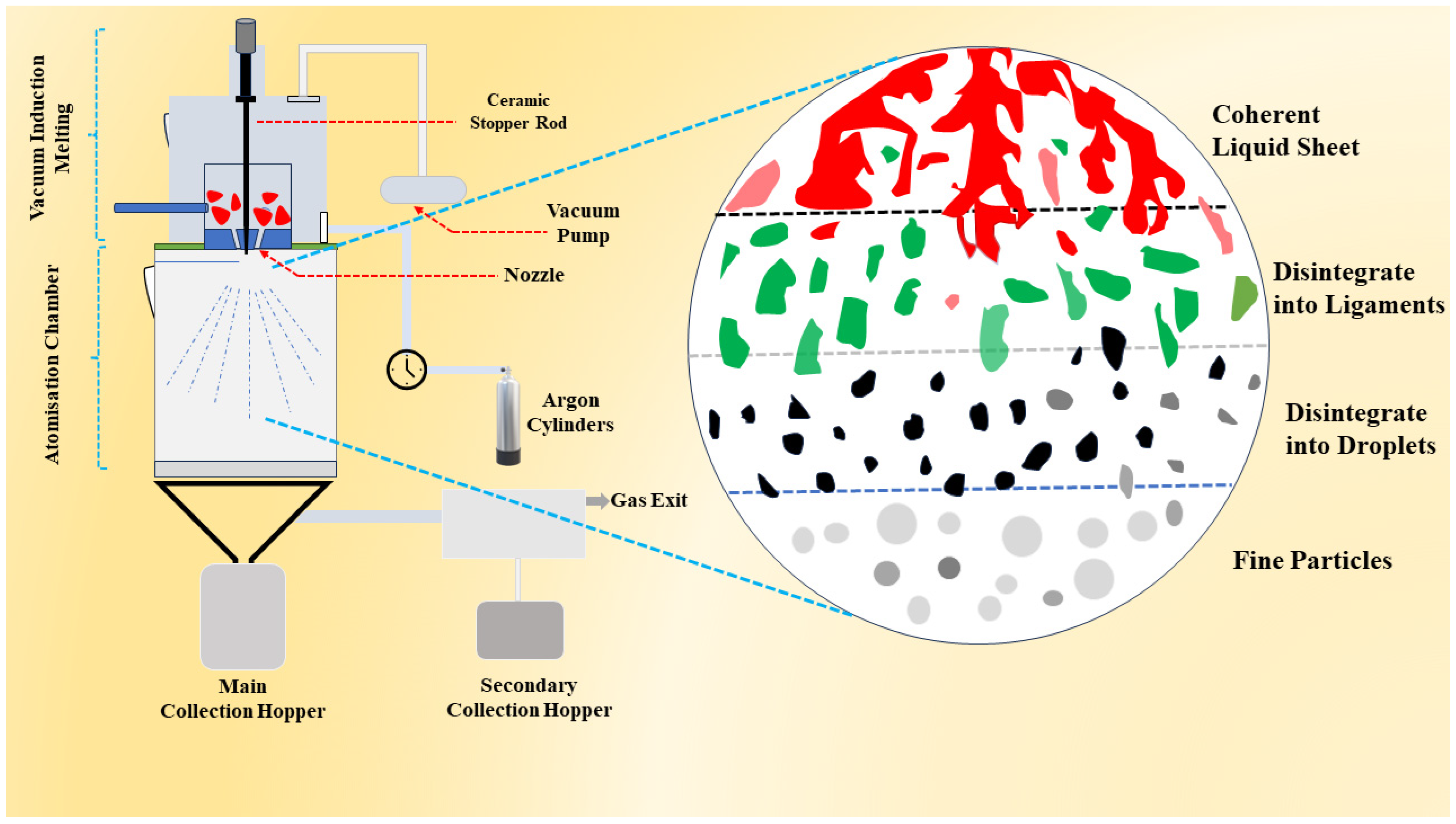
2.1. Powder Production

The powders of the two Al-Fe-Si-Cr-Ni compositions were produced by our research group through a close inert gas atomisation process with PSI HERMIGA 100/10 VI lab scale atomiser equipped with a ceramic nozzle ø 2.5 mm. The AlFe9Si8Cr2Ni and AlFe18Si8Cr5Ni2 compositions were obtained starting from AISI 304L, and AlSi10Mg ingots in a ratio of 1:3 and 1:8, respectively. The chemical compositions of AlSi10Mg and AISI 304L ingots utilised as the initial feedstock for atomisation are reported in Table 1 and Table 2.
The ingots were subjected to vacuum induction melting in an Al2O3 crucible and were maintained at a superheat of 1000 °C for 1 h to ensure thorough and complete melting. In fact, as suggested by the ternary isothermal section of the Al-Si-Fe phase diagram, only the liquid phase is presented at 1000 °C [16]. After the melting process, the flow of molten metal into the atomisation chamber was initiated by opening the valve at the bottom of the crucible. As illustrated in Figure 1, the high-velocity jet of argon gas hits the molten metal as it falls, disintegrating it into numerous microdroplets that give rise to particles of different sizes. During gas atomisation, the disintegrated molten droplet is subjected to surface tension, drag, and buoyancy forces, and the balance of these forces results in an almost spherical morphology of the powder particles. The atomisation of the molten metal stream was carried out at a die pressure of 26 ± 1.25 bar, a gas flow rate of 2.55 ± 0.10 kg/ min, a gas-to-metal ratio of 3.19 ± 0.01, and a top pressure of 0.25 bar. In order to prevent surface oxidation of the particles, an inert high-purity argon atmosphere was used during the whole gas-atomisation process. In addition, due to the high reactivity of the Al-based compositions, a passivation step was carried out after gas atomisation to prevent explosivity issues.

2.2. Powder Characterisations

Before proceeding with the characterisation, the composition of the gas-atomised powders was assessed by performing the energy dispersive spectrometer (EDS) analysis on 10 particles for each system, as reported in Table 3.
The particle size distribution (PSD) of the gas-atomised powders was assessed using the laser scattering technique with the Mastersizer 3000 analyser (Malvern Panalytical, Malvern, UK & Almelo, The Netherlands). To observe the particle morphology, the gas-atomised powders of the two compositions were analysed on stab by the Phenom XL scanning electron microscope (SEM, Phenom, Ambler, PA, USA). To verify the internal defects, the powders were mounted in hot resin and subjected to a dedicated metallographic preparation for a mirror-like finishing. Their cross-sections were observed by a Leica DMI500 optical microscope (OM, Leica Camera AG, Wetzlar, Germany).
The powders of both compositions were sieved following the ASTM B 215 standard using a Retsch AS 200 basic mechanical sieving shaker (Retsch, Haan, Germany), resulting in the following batches: <20 μm, 20–50 μm, and >50 μm. In order to investigate the effect of particle sizes and, thus, of different cooling rates on the morphology and composition of the present phases and the overall microstructure of AlFe9Si8Cr2Ni and AlFe18Si8Cr5Ni2 powders, a detailed microstructural analysis was conducted by using a Phenom XL SEM with a back-scattered electron detector (BSE) detector operating at a voltage of 15 kV. To investigate the different amounts of alloying elements on the microstructural properties of Al-Fe-Si-Cr-Ni systems, the 20–50 μm particle size range was selected. X-ray diffraction (XRD) analyses for phase identification and microchemical analyses by EDS detector for phase morphology and distribution investigation were conducted on the AlFe9Si8Cr2Ni and AlFe18Si8Cr5Ni2 20–50 μm batches. The XRD analyses were performed at 40 kV and 40 mA in a Bragg–Brentano configuration, using CuKα radiation. The XRD data was recorded in the 2θ range of 20 to 90° with a step size of 0.013° and a counting time of 45 s at each step. The phase identification procedure was performed by HighScore software (version 3.0d, Malvern Panalytical, Malvern, UK & Almelo, The Netherlands). EDS point, line, and map analyses coupled with SEM investigation in backscattered mode were employed to verify the presence of the phases identified from the XRD spectra and assess the differences in phase morphology and distribution as the alloying elements increase. The reaction sequences for AlFe9Si8Cr2Ni and AlFe18Si8Cr5Ni2 were determined through differential scanning calorimetry (DSC) analysis using the NETZSCH DSC 214 Polyma instrument (NETZSCH, Bayern, Germany). The DSC tests were conducted on the powder samples, each weighing approximately 75 mg. The heating rate was maintained at 10 °C/min, and the temperature ranged from 20 to 700 °C. At the same time, the cooling rate was maintained at 20 °C/min. The thermal analyses employed an Al2O3 crucible and a protective argon atmosphere.

3. Results

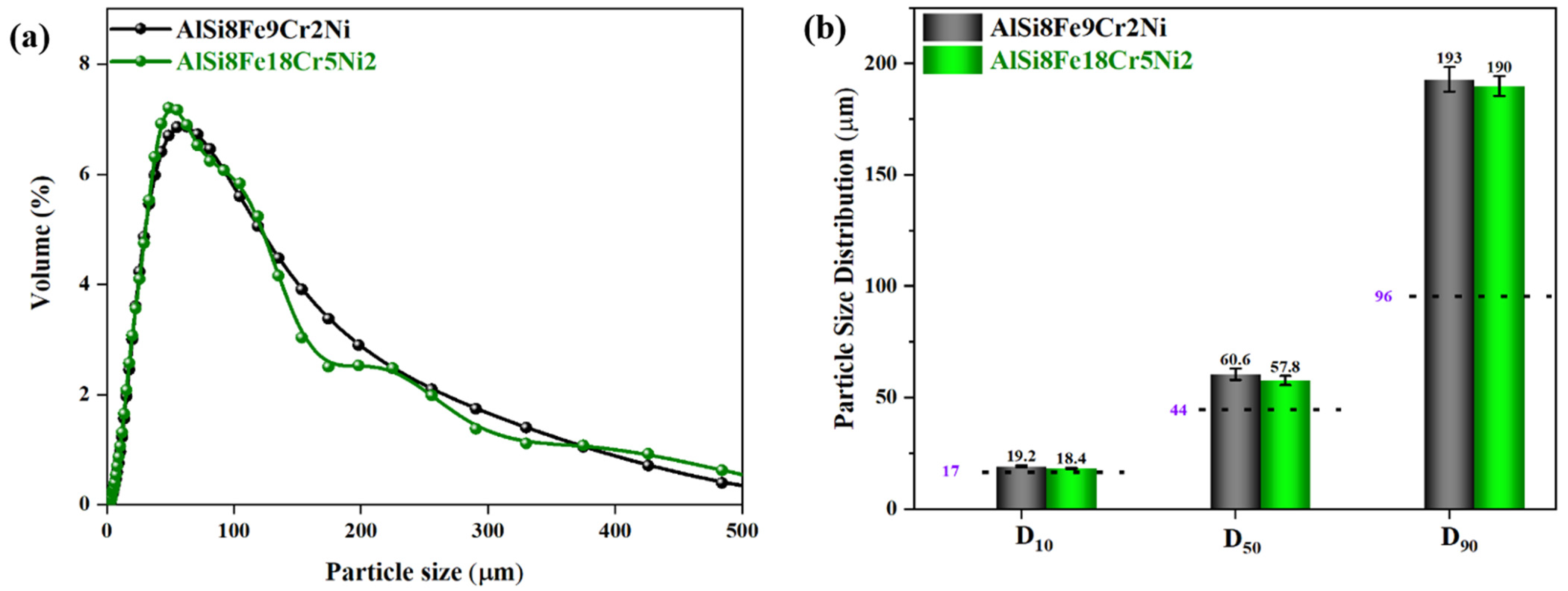
3.1. Particle Size Distribution

The PSDs of unsieved, gas-atomised powders are depicted in Figure 2a.
The particle size distribution curves appear asymmetrical for both compositions, with a sharp peak on the fine fractions and a marked tail towards the coarser fractions. The wide distribution can be attributed to the density and, thus, the viscosity in the liquid state of the two compositions. Indeed, the viscosity of the melt during gas atomisation influences the breakup of the molten metal stream into droplets, playing a crucial role in determining the size distribution of the metal powder particles obtained. Looking closer at the statistical parameters obtained from the cumulative PSDs reported in Figure 2b, it can be seen that the D10, D50, and D90 percentiles for AlFe9Si8Cr2Ni and AlFe18Si8Cr5Ni2 compositions are very similar to each other but appear much higher than the pure AlSi10Mg alloy (the AlSi10Mg references shown in dotted lines in Figure 2b pertain to a parallel study by the authors). In particular, D50 and D90 percentiles are more than 30 and 100%, respectively, higher than pure AlSi10Mg in both Al-Fe-Si-Cr-Ni alloys. This can be justified by the presence of Fe, Cr, and Ni as additional alloying elements that can alter the atomic arrangement and packing, impacting the viscosity. Based on studies conducted on the influence of Fe on the castability and properties of Al-Si alloys [3], it can be established that the addition of Fe as an alloying element in quasi-eutectic Al-Si alloys alters the local structure of the liquid, affecting the ease with which atoms move past each other. This leads to a drop in fluidity and, thus, an increase in melt viscosity. To the best of the authors’ knowledge, the effects of Ni and Cr in Al-Si alloys have not been extensively investigated in the literature. Still, their limited presence in both compositions makes it plausible to assume that the presence of Cr and Ni may not significantly alter the increase in viscosity given by Fe. Higher viscosity leads to larger droplets during gas atomisation that tend to solidify more slowly, resulting in a larger final particle size [17].

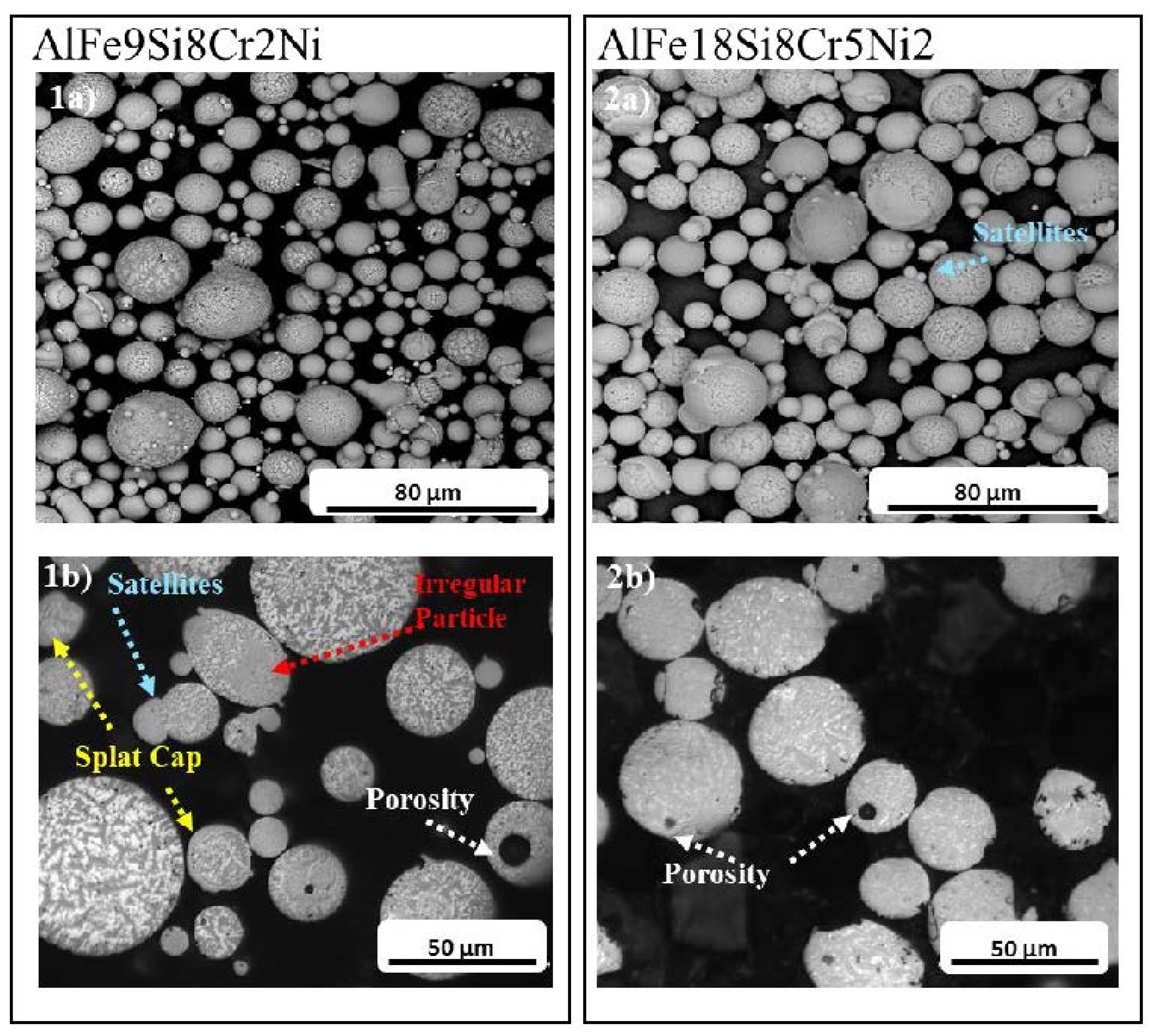
3.2. Morphological Characterisation

During atomisation, the disintegrated molten droplets are subjected to surface tension, drag, and buoyancy forces, and the balance of these forces should result in an almost spherical morphology of the powder particles [18]. However, the use of the gas jet to break up the molten stream, turbulence that may occur close to the nozzle, or unintentional droplet collisions during gas atomisation may lead to powder defects that compromise the packaging, flowability, and spreadability of powder properties [19]. To verify the morphological conditions and the presence of internal defects in the AlFe9Si8Cr2Ni and AlFe18Si8Cr5Ni2 powders, optical analyses were conducted on the intact and cross-sectioned particles by SEM and OM (Figure 3).
As it is possible to observe in the micrographs reported in Figure 3(1a,2a), the majority of gas-atomised particles exhibited a nearly spherical morphology in both Al-Fe-Si-Cr-Ni compositions. However, some particles displayed splat caps and irregular shapes. When a collision between a completely liquid droplet and a fully solidified particle occurs, splat caps like the ones indicated with yellow arrows in Figure 3(1b) could be formed [20]. In addition, unintentional collisions between droplets during solidification could result in shape deformation (indicated with red arrows in Figure 3(1b)) [20]. Such defects have detrimental effects on the powder properties; however, they are rarely present in the analysed powders. As shown in blue in Figure 3(1b,2a), the presence of satellites is also highly limited in both Al-Fe-Si-Cr-Ni compositions. Turbulence in the near-nozzle region that can occur during argon gas outflow at sonic velocity can generate the formation of tiny, already solidified particles, which can adhere to larger particles due to surface tension forces creating “outer satellites” or to molten droplets forming “embedded satellites” [21]. The poor occurrence of this defect in the analysed systems can be explained by the high viscosity of the molten stream due to the conspicuous presence of Fe in both alloys, which allows a slower, more stable gas atomisation process and the limited formation of ultra-fine particles. Additionally, there is no observable indication of open porosity in both compositions. Upon closer inspection of the particle surfaces of AlFe9Si8Cr2Ni and AlFe18Si8Cr5Ni2, a discernible dendritic pattern could be easily observed. Micrographs on the cross-sectioned powders reported in Figure 3(1b,2b) revealed limited levels of internal porosity. This defect is widespread in gas-atomised powders, as argon can become trapped in the molten droplet during chamber blowing [14]. The limited presence of internal porosity indicates the quality and stability of the atomisation process and makes the powders suitable for processing by PB-AM.

3.3. Effect of Cooling Rate on Microstructural Evolution of AlFe9Si8Cr2Ni and AlFe18Si8Cr5Ni2 Powders

The growth morphology of molten droplets during solidification is influenced by factors such as the solid–liquid interface’s curvature, the solid–liquid interface’s velocity, and the temperature gradient at this interface [22]. In order to investigate the effect of cooling rate and thus of particle size on the morphological evolution of the powders, AlFe9Si8Cr2Ni and AlFe18Si8Cr5Ni2 particles sieved below 20 µm, between 20 and 50 µm, and above 50 µm were observed in cross sections by SEM.
Both compositions show the presence of three different phases: one with a higher atomic weight (brighter in the BSE image), one with a lower atomic weight (grey in the BSE image), and one with the lowest atomic weight (darker grey/black in the BSE image). Starting from the analysis of the composition with the lowest content of alloying elements (AlFe9Si8Cr2Ni), it is possible to observe the outgrowth of fine dendrites from the liquid phase, a characteristic feature of rapid solidification [23]. Paying attention to the brighter phase, a significant microstructural variation can be observed as a function of the particle size. In particular, in the finer particles, cellular growth morphology can be observed (Figure 4(1a)), which changes into a dendritic one when the particle size increases (Figure 4(1b,1c)). The cooling rate of a molten droplet is intimately related to the heat extraction rate from the liquid droplet by the atomising gas [24]. Heat extraction from a droplet is the culmination of conductive heat transfer from the core of the droplet to the surface, convective heat transfer by the atomising gas from the droplet’s surface, and heat transfer by radiation from the solidifying droplet. Thus, the heat transfer rate during solidification of molten droplets depends on the droplet size. Rapid heat transfer occurs in fine droplets, whereas heat transfer is comparatively sluggish for coarser droplets. Therefore, the droplet size is directly related to its cooling rate, which, in turn, influences the solidification microstructure [25]. Generally, there is a limited solute redistribution in front of the solid–liquid interface under high cooling rates. As a result, the finest particles are characterised by a globular microstructure that has not had sufficient time to evolve and create the dendritic morphology. This could explain the reason why, with increasing size, the dendritic structure appears progressively more evident. It can also be noted how the darker (black-like) phase seems not to be present in the finer particles and increases in quantity as the size increases. To name these phases, please refer to the EDS analysis results in Section 3.4.2.
Observing the BSE micrographs of AlFe18Si8Cr5Ni2 particles, it is evident that the solidification front, specifically dendritic solidification, remains consistent regardless of the particle size. This lower susceptibility of the morphology to particle size can be traced back to the conspicuous presence of iron in the alloy, which leads to an increase in the viscosity of the molten stream and, thus, to higher stability of the gas atomisation process. However, with increasing particle size, it is possible to note that the discontinuous dendrites become increasingly continuous, and their dimensions increase. In particular, the mean length of primary dendrites exhibited fluctuation, ranging from 4 to 7 μm for particles with diameters below 20 μm, 10 to 15 μm for particles with diameters 20–50 μm, and 15 to 20 μm for particles with diameters above 50 μm. This can be attributed to the lower cooling rate and, thus, the longer solidification time that characterises coarser particles and allows dendrites to grow. Furthermore, some particles exhibit multiple nucleation sites within a single particle (indicated in red in Figure 4(2a)). These nucleation sites are located on the powder’s outer surface, which may be related to the strong thermal convection prevailing in that area.

3.4. Compositional Characterisation

In order to investigate the amount and the distribution of the alloying elements for the two compositions, XRD analyses for phase identification and microchemical analyses by EDS for phase distribution investigation were conducted on AlFe9Si8Cr2Ni and AlFe18Si8Cr5Ni2 powders. Based on the above-described microstructural variations upon different particle sizes of the AlFe9Si8Cr2Ni composition, it was decided to use the median range of 20–50 µm as a representative sample for the compositional analysis of the powders.

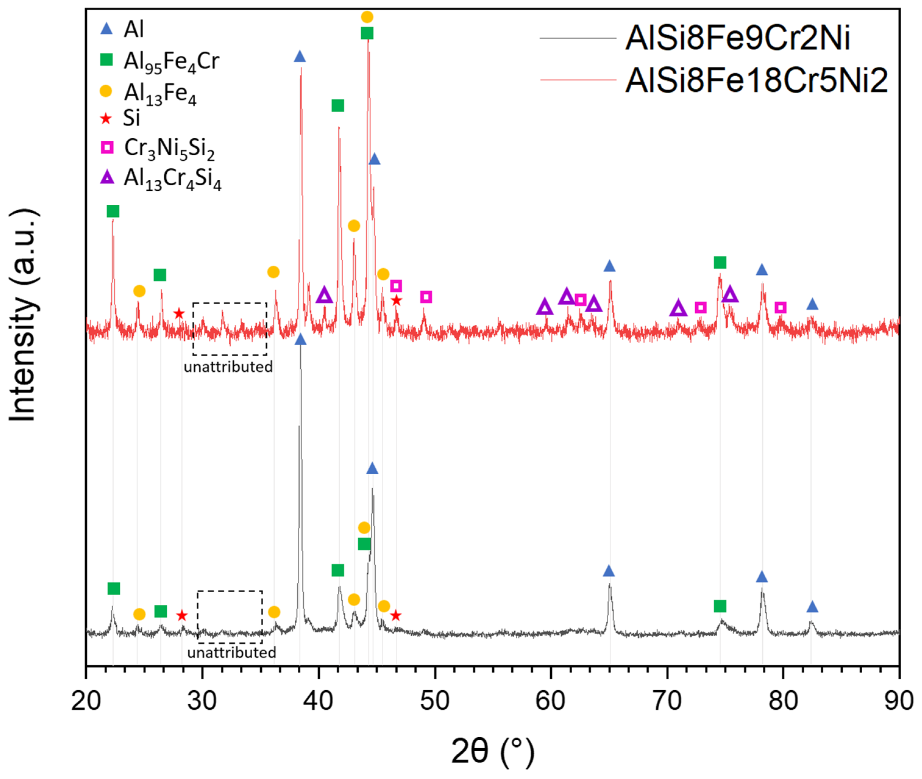
3.4.1. Phase Identification through XRD

XRD analysis was used to determine how different amounts of alloying elements in the AlFe9Si8Cr2Ni and AlFe18Si8Cr5Ni2 systems affect the presence and amount of intermetallic phases. Analysing the XRD spectrum of AlFe9Si8Cr2Ni shown in black in Figure 5, it was possible to identify the most intense peaks related to the fcc-Al constituting the matrix of the system, other peaks mainly attributable to two intermetallic phases, Al95Fe4Cr and Al13Fe4, and two weak peaks associable with the presence of Si diamond cubic. Some smooth peaks can be detected in the 29–35° range, but due to their low intensity, the software was not able to provide a reliable attribution. However, the literature pertaining to Al-Fe-Si alloys reported XRD peaks in the 20–35 range for α-Al8Fe2Si and/or β-Al5FeSi phases [6,26]. In particular, Lan et al. [6] reported that the eutectic α-Al8Fe2Si phase is favoured in Al-Fe-Si compositions as the cooling rate and Fe-Si ratio increase. Based on the rapid cooling rates involved in the gas atomisation process and the high Fe-Si ratio of the AlFe9Si8Cr2Ni system (around 1.25), it is reasonable to assume that the eutectic phase may occur. However, further analyses are required to verify this assumption. According to the XRD spectrum analysis, it can be stated that only Si and Al are present as pure elements. At the same time, Fe reacts in its entirety with Al and other alloying elements, and Cr reacts preferentially with Al and Fe. Peaks related to Ni or Ni-containing phases were not identified. Still, it is not possible to definitively state if the absence can be attributed to the presence of Ni completely in solid solution or if it is related to the low amount of the element in the composition as quantities below 1.0 wt.% are not detectable with XRD analysis.
Moving to the observation of the XRD spectrum of AlFe18Si8Cr5Ni2 displayed in red in Figure 5, it can be noted that the phases detected in the system with a lower amount of alloying elements are still present, but the peak relative intensity is different, and the spectrum overall appears much noisier and with a massive presence of additional peaks. Looking at the phases already identified in the AlFe9Si8Cr2Ni system, it is evident that the presence of Al95Fe4Cr and Al13Fe4 is more conspicuous. In fact, the dominant peak in the AlFe18Si8Cr5Ni2 XRD spectrum is no longer the Al (111) peak (38.37°) but is the one at 44.18° given by the co-presence of the main peak of the Al95Fe4Cr phase and the third most intense peak of the Al13Fe4 phase. Furthermore, it can be seen that Si is no longer present only as a pure element but seems to react with Al, Cr, and Ni, resulting in two other intermetallic phases not identified in the AlFe9Si8Cr2Ni system: Cr3Ni5Si2 and Al13Cr4Si4. The appearance of the peaks relative to the Cr3Ni5Si2 phase is in line with the higher amount of Ni in the composition that makes it detectable by XRD analysis and suggests that Ni reacts preferentially with Cr and Si rather than with the Al matrix or the second most abundant element in the alloy (Fe). In addition, the smooth peaks detected in the 29–35° range of the AlFe9Si8Cr2Ni system appear more intense in the AlFe18Si8Cr5Ni2 spectrum. Still, due to the high signal noise and the co-presence of numerous peaks referable to Al,Fe and Al,Fe,Si-containing phases in that angle range, it was not possible to provide a reliable attribution. A more accurate attribution of unassigned peaks has been postponed until microstructural analyses have been conducted.

3.4.2. Compositional Analysis by EDS

Scanning electron micrographs obtained with the BSE detector revealed, for both compositions, dendritic structures with higher atomic weights and an interdendritic region with a higher atomic weight. Looking closer at AlFe9Si8Cr2Ni particles, the interdendritic region appears to consist of an extended heavier phase (grey) and a brighter, less diffuse phase (black). To name the phases identified in the BSE micrographs, an EDS compositional analysis was conducted.
From the EDS maps reported in Figure 6, it is possible to note that the dendritic structures are clearly enriched in Fe. In addition, the distribution of Fe matches the Cr-enriched area. This result appears to be in line with the Al95Fe4Cr phase found by the XRD analysis. Based on the low amount of Ni, its distribution is not reliably recognised by the EDS maps. Furthermore, Si and Al appeared widely present over the entire analysed surface, and for this reason, it was decided not to report their maps. To investigate the composition of the grey interdendritic areas, a line EDS analysis was performed. The latter recognised an alternation of Si and Al resembling the Al-Si lamellar structure typical of AlSi10Mg. These Al-Si alternations may support the assumption of the presence of Al-Fe-Si phases (also eutectic) made on unassigned peaks identified in the XRD pattern. In addition, their sub-micrometric dimensions could explain the low intensity of the relative XRD peaks.
Observing the EDS maps reported in Figure 7, it is possible to note that in line with the results obtained for the Al-Fe-Si-Cr-Ni with a lower amount of alloying elements, also in AlFe18Si8Cr5Ni2 particles, the dendritic structures are clearly enriched in Fe. However, in this case, Cr does not seem to mirror the distribution of Fe perfectly but appears almost uniformly distributed over the entire area analysed. The more widespread presence of Cr justifies the conspicuous appearance of silicon-containing phases such as Cr3Ni5Si2 and Al13Cr4Si4 identified by the XRD spectrum. Silicon is more present in Fe-poor areas and has few scattered pure (or particularly enriched) submicron particles. This confirms the presence of pure Si found in the XRD spectrum.

3.4.3. Thermal Analysis by DSC

DSC was used to investigate the precipitation or dissolution reactions of AlFe9Si8Cr2Ni and AlFe18Si8Cr5Ni2 powders. The profile of DSC peaks can, in fact, reveal the occurrence of exothermic or endothermic processes. In particular, the exothermic reaction involves the nucleation and growth of precipitates, releasing energy, while the endothermic reaction corresponds to the dissolution or melting of phases, requiring energy input.
Observing the AlFe9Si8Cr2Ni DSC curve reported in Figure 8, it is possible to note two endothermic peaks between 560 and 620 °C (as onset and offset values). The first peak could be attributable to the melting of the Al-Si eutectic observed by EDS analysis. In fact, the peak temperature (580 °C) is very close to the eutectic temperature of the Al-Si phase diagram (577 °C). Analogously, the second peak could be related to the α-Al melting temperature. In the same temperature range, two endothermic peaks were also detected in the DSC curve of AlFe18Si8Cr5Ni2, as shown in Figure 8. However, here, the peaks appear much less intense, especially the peak relating to the Al-Si eutectic phase, which seems so weak that it reverses the trend and makes the second peak emerge as the most intense. The different nature of the AlFe18Si8Cr5Ni2 DSC peaks could be related to what was observed by EDS and XRD analyses. In particular, XRD and EDS analyses performed on the AlFe18Si8Cr5Ni2 powder revealed that Si tends to form several phases with the other alloying elements, reducing the amount of silicon available for Al. The lower amount of available silicon for Al ideally leads to a shift in the Al-Si phase diagram, resulting in a higher α-Al phase, less liquid available to create the eutectic phase, and a higher α-Al melting temperature. This would explain not only the less intense nature of the peaks in the AlFe18Si8Cr5Ni2 system but also the slight shift to higher temperatures observed in the second peak. The spectra revealed other minor endothermic and exothermic peaks at lower temperatures that may be correlated with the dissolution or precipitation of low-melting phases. However, it is reasonable to assume that reactions related to the higher melting phases, such as Al95Fe4Cr, Cr3Ni5Si2, and Al13Cr4Si4, occur at higher temperatures and are therefore excluded from the analysis performed.
DSC analyses performed up to 700 °C did not lead to the complete melting of gas-atomised powders. In fact, the powders appeared only partially sintered after DSC analysis. Based on this experimental evidence, it can be asserted that adding 304L to AlSi10Mg led to a significant increase in melting temperature. The study performed by Marola et al. [27] on the AlSi10Mg alloy processed by rapid solidification revealed a melting temperature of below 600 °C. Future analyses at higher temperatures will be conducted to evaluate the reactions related to the higher melting phases detected by XRD and EDS analyses and to quantify the increase in melting temperature in the two systems.

4. Conclusions

This research looked into two previously unexplored gas-atomised Al-Fe-Si-Cr-Ni compositions. To emphasise the importance of sustainability in the development of novel alloys, two widespread alloys in industrial processes, AlSi10Mg and AISI 304L, were used as starting materials for gas atomisation. The selected compositions, AlFe9Si8Cr2Ni and AlFe18Si8Cr5Ni2, were extensively analysed from compositional and microstructural points of view, focusing on alloying element content and particle size. The results obtained are summarised below:
  • IGAed compositions exhibited asymmetrical PSD curves, with D50 and D90 percentiles higher than AlSi10Mg, attributed to the presence of Fe, Cr, and Ni altering the molten stream viscosity during gas atomisation.
  • AlFe9Si8Cr2Ni and AlFe18Si8Cr5Ni2 particle morphologies were predominantly spherical, with just a limited presence of defects.
  • Al-Fe-Si-Cr-Ni powders observed with the BSE detector showed a dendritic pattern with three distinct phases. In AlFe9Si8Cr2Ni, fine particles displayed cellular growth, transitioning to dendritic morphology as particle size increased. In contrast, the AlFe18Si8Cr5Ni2 composition exhibited more elongated and consistent dendritic solidification regardless of particle size.
  • In XRD analysis, AlFe9Si8Cr2Ni exhibited intense peaks of fcc-Al, with additional peaks mainly attributed to intermetallic phases Al95Fe4Cr and Al13Fe4. In AlFe18Si8Cr5Ni2, the same but more pronounced peaks were detected with the addition of peaks related to the presence of the Cr3Ni5Si2 and Al13Cr4Si4 phases.
  • EDS mapping of AlFe9Si8Cr2Ni particles showed dendritic structures enriched in Fe and Cr, confirming the Al95Fe4Cr phase detected with XRD, and interdendritic regions with Al-Si alternations resembling the lamellar structure of AlSi10Mg. In AlFe18Si8Cr5Ni2, dendritic structures appeared to be enriched in Fe and Cr, Al-Si alternations were not detected, and the more uniform Cr distribution justifies the appearance of Cr-containing phases identified by XRD.
  • DSC analyses confirmed the higher amount of eutectic Al-Si in the AlFe9Si8Cr2Ni system and revealed a melting temperature of the two compositions well above that of AlSi10Mg.

Author Contributions

Conceptualization, P.F. and M.L.; investigation, A.M., B.B., F.G. and E.V.; data curation, A.M., B.B. and M.L.; writing—original draft preparation, A.M.; writing—review and editing, A.M., B.B., F.B., F.G., D.M. and M.L.; supervision, F.B., D.M., M.L. and P.F. All authors have read and agreed to the published version of the manuscript.

Funding

This research received no external funding.

Data Availability Statement

The data presented in this study are available on request from the corresponding author. The data are not publicly available due to privacy.

Conflicts of Interest

The authors declare no conflict of interest.

References

  1. Cáceres, C.H.; Selling, B.I. Casting Defects and the Tensile Properties of an Al-Si-Mg Alloy. Mater. Sci. Eng. A 1996, 220, 109–116. [Google Scholar] [CrossRef]
  2. Javidani, M.; Larouche, D. Application of Cast Al-Si Alloys in Internal Combustion Engine Components. Int. Mater. Rev. 2014, 59, 132–158. [Google Scholar] [CrossRef]
  3. Mbuya, T.O.; Odera, B.O.; Ng’ang’a, S.P. Influence of Iron on Castability and Properties of Aluminium Silicon Alloys: Literature Review. Int. J. Cast Met. Res. 2003, 16, 451–465. [Google Scholar] [CrossRef]
  4. Callegari, B.; Lima, T.N.; Coelho, R.S. The Influence of Alloying Elements on the Microstructure and Properties of Al-Si-Based Casting Alloys: A Review. Metals 2023, 13, 1174. [Google Scholar] [CrossRef]
  5. Seifeddine, S.; Johansson, S.; Svensson, I.L. The Influence of Cooling Rate and Manganese Content on the β-Al5FeSi Phase Formation and Mechanical Properties of Al-Si-Based Alloys. Mater. Sci. Eng. A 2008, 490, 385–390. [Google Scholar] [CrossRef]
  6. Lan, X.; Li, K.; Wang, J.; Yang, M.; Lu, Q.; Du, Y. Developing Al–Fe–Si Alloys with High Thermal Stability through Tuning Fe, Si Contents and Cooling Rates. Intermetallics 2022, 144, 107505. [Google Scholar] [CrossRef]
  7. Petr, J. The Iron Correctors in Al-Si Alloys. Int. J. Eng. 2011, 9, 401–405. [Google Scholar]
  8. Aranda, V.A.; Figueroa, I.A.; González, G.; García-Hinojosa, J.A.; Alfonso, I. Study of the Microstructure and Mechanical Properties of Al-Si-Fe with Additions of Chromium by Suction Casting. J. Alloys Compd. 2021, 853, 157155. [Google Scholar] [CrossRef]
  9. Školáková, A.; Novák, P.; Vojtěch, D.; Kubatík, T.F. Microstructure and Mechanical Properties of Al-Si-Fe-X Alloys. Mater. Des. 2016, 107, 491–502. [Google Scholar] [CrossRef]
  10. Petrík, J. The Application of Ni for Improvement of Al-Si-Fe Alloys. Mater. Eng. 2009, 16, 29–32. [Google Scholar]
  11. Xavier, M.G.C.; Freitas, B.J.M.; Koga, G.Y.; Spinelli, J.E. Effects of Ni and Co on the Corrosion Resistance of Al-Si-Cu-Zn-Fe Alloys in NaCl Solution. Metals 2022, 12, 645. [Google Scholar] [CrossRef]
  12. Lavernia, E.J.; Srivatsan, T.S. The Rapid Solidification Processing of Materials: Science, Principles, Technology, Advances, and Applications. J. Mater. Sci. 2010, 45, 287–325. [Google Scholar] [CrossRef]
  13. Dunkley, J.J. Metal Powder Atomisation Methods for Modern Manufacturing. Johns. Matthey Technol. Rev. 2019, 63, 226–232. [Google Scholar] [CrossRef]
  14. Chen, G.; Zhao, S.Y.; Tan, P.; Wang, J.; Xiang, C.S.; Tang, H.P. A Comparative Study of Ti-6Al-4V Powders for Additive Manufacturing by Gas Atomization, Plasma Rotating Electrode Process and Plasma Atomization. Powder Technol. 2018, 333, 38–46. [Google Scholar] [CrossRef]
  15. Jones, H. On the Prediction of Lattice Parameter vs. Concentration for Solid Solutions Extended by Rapid Quenching from the Melt. Scr. Metall. 1983, 17, 97–100. [Google Scholar] [CrossRef]
  16. Geoffrey, V.; Raynor, V.G.R. Phase Equilibria in Iron Ternary Alloys: A Critical Assessment of the Experimental Literature; Institute of Metals: London, UK; Institute of Metals North American Publications Center: Brookfield, VT, USA, 1988. [Google Scholar]
  17. Ünal, A. Effect of Processing Variables on Particle Size in Gas Atomization of Rapidly Solidified Aluminium Powders. Mater. Sci. Technol. 1987, 3, 1029–1039. [Google Scholar] [CrossRef]
  18. Prasad, A.; Mosbah, S.; Henein, H.; Gandin, C.A. A Solidification Model for Atomization. ISIJ Int. 2009, 49, 992–999. [Google Scholar] [CrossRef]
  19. Zhao, Y.; Cui, Y.; Hasebe, Y.; Bian, H.; Yamanaka, K.; Aoyagi, K.; Hagisawa, T.; Chiba, A. Controlling Factors Determining Flowability of Powders for Additive Manufacturing: A Combined Experimental and Simulation Study. Powder Technol. 2021, 393, 482–493. [Google Scholar] [CrossRef]
  20. Fischmeister, H.F.; Ozerskii, A.D.; Olsson, L. Solidification Structure of Gas-Atomized High-Speed Steel Powders. Powder Metall. 1982, 25, 1–9. [Google Scholar] [CrossRef]
  21. Xiong, L.; Chuang, A.C.; Thomas, J.; Prost, T.; White, E.; Anderson, I.; Singh, D. Defect and Satellite Characteristics of Additive Manufacturing Metal Powders. Adv. Powder Technol. 2022, 33, 103486. [Google Scholar] [CrossRef]
  22. Kumar, G.S.; Sateshwar, M.; Sharma, A.R.; Palit, M.; Sarkar, R.; Ghosal, P.; Rao, G.A. Particle Size Dependent Microstructure Evolution of Inert Gas Atomized Nickel Base Superalloy Powders. J. Alloys Compd. 2022, 909, 164772. [Google Scholar] [CrossRef]
  23. Dai, Y.; Yang, M.; Song, C.; Han, Q.; Zhai, Q. Solidification Structure of C2.08Cr25.43Si1.19Mn0.43Fe70.87 Powders Fabricated by High Pressure Gas Atomization. Mater. Charact. 2010, 61, 116–122. [Google Scholar] [CrossRef]
  24. Fang, P.; Xu, Y.; Li, X.; Chen, Y. Influence of Atomizing Gas and Cooling Rate on Solidification Characterization of Nickel-Based Superalloy Powders. Xiyou Jinshu Cailiao Yu Gongcheng/Rare Met. Mater. Eng. 2018, 47, 423–430. [Google Scholar] [CrossRef]
  25. Bassini, E.; Galech, U.; Soria, T.; Aristizabal, M.; Iturriza, I.; Biamino, S.; Ugues, D. Effect of the Particle Size Distribution on Physical Properties, Composition, and Quality of Gas Atomized Astroloy Powders for HIP Application. J. Alloys Compd. 2022, 890, 161631. [Google Scholar] [CrossRef]
  26. Song, D.; Zhao, Y.; Jia, Y.; Li, R.; Zhou, N.; Zheng, K.; Fu, Y.; Zhang, W. Study of the Evolution Mechanisms of Fe-Rich Phases in Al-Si-Fe Alloys with Mn Modification Using Synchrotron X-ray Imaging. J. Alloys Compd. 2022, 915, 165378. [Google Scholar] [CrossRef]
  27. Marola, S.; Manfredi, D.; Fiore, G.; Poletti, M.G.; Lombardi, M.; Fino, P.; Battezzati, L. A comparison of Selective Laser Melting with bulk rapid solidification of AlSi10Mg alloy. J. Alloys Compd. 2018, 742, 271–279. [Google Scholar] [CrossRef]
Figure 1. Schematic illustration of the Al-Fe-Si-Cr-Ni alloy development by close-coupled IGA.
Metals 14 00017 g001
Figure 2. (a) Particle size distribution of gas-atomised powders. (b) D10, D50, and D90 percentiles of AlFe9Si8Cr2Ni and AlFe18Si8Cr5Ni2 compositions.
Metals 14 00017 g002
Figure 3. (a) SEM micrographs, and (b) optical images of cross-sectioned particles of gas-atomised AlFe9Si8Cr2Ni (1) and AlFe18Si8Cr5Ni2 (2) powders.
Metals 14 00017 g003
Figure 4. SEM micrographs of cross-sectioned particles of gas-atomised AlFe9Si8Cr2Ni (1) and AlFe18Si8Cr5Ni2 (2) powders ((a) <20 μm (b) 20–50 μm (c) >50 μm).
Metals 14 00017 g004
Figure 5. XRD patterns of 20–50 μm sieved AlFe9Si8Cr2Ni and AlFe18Si8Cr5Ni2 powders.
Metals 14 00017 g005
Figure 6. Cross-sectional SEM-EDS maps on cross-sectioned AlFe9Si8Cr2Ni powder with an SEM-EDS line scan in the interdendritic region (grey zone).
Metals 14 00017 g006
Figure 7. Cross-sectional SEM-EDS maps on cross-sectioned AlFe18Si8Cr5Ni2 powder.
Metals 14 00017 g007
Figure 8. DSC signals for AlFe9Si8Cr2Ni and AlFe18Si8Cr5Ni2 powders.
Metals 14 00017 g008
Table 1. Composition of AISI 304L.
ElementsCrNiCMnPSSiNFe
Composition
(wt.%)
18.08.00.021.500.030.030.410.08Bal
Table 2. Composition of AlSi10Mg.
ElementsSiMgFeMnZnAl
Composition
(wt.%)
9.0–11.00.2–0.450.550.450.10Bal
Table 3. Chemical composition of the gas-atomised Al-Fe-Si-Cr-Ni powders.
AlloyFeSiCrNiAl
AlFe9Si8Cr2Ni (wt.%)9.14 ± 0.308.60 ± 0.381.82 ± 0.100.77 ± 0.07Bal
AlFe18Si8Cr5Ni2 (wt.%)18.73 ± 0.457.42 ± 0.205.82 ± 0.282.12 ± 0.02Bal
Disclaimer/Publisher’s Note: The statements, opinions and data contained in all publications are solely those of the individual author(s) and contributor(s) and not of MDPI and/or the editor(s). MDPI and/or the editor(s) disclaim responsibility for any injury to people or property resulting from any ideas, methods, instructions or products referred to in the content.

