Article

Synergic Effects of Nanosecond Laser Ablation and PVD-Coating on Cemented Carbides: Assessment on Surface and Mechanical Integrity

1
Department of Mechanical and Aerospace Engineering, Rutgers University-New Brunswick, Piscataway, NJ 08854, USA
2
CIEFMA—Department of Materials Science and Metallurgical Engineering, EEBE—Campus Diagonal Besòs, Universitat Politècnica de Catalunya, 08019 Barcelona, Spain
3
Institute of Production Engineering, Saarland University, 66123 Saarbrücken, Germany
*
Author to whom correspondence should be addressed.
Metals 2024, 14(1), 34; https://doi.org/10.3390/met14010034
Submission received: 25 November 2023 / Revised: 25 December 2023 / Accepted: 26 December 2023 / Published: 28 December 2023

Abstract

:
Emerging laser precision machining, particularly using pulsed lasers, enlightens the innovation and functionalization of cemented carbides. These backbone materials of the tooling industry are usually considered difficult to machine or shape using conventional mechanical approaches. The coating of cemented carbide tools, deemed to improve their mechanical and thermal properties, is a common supplementary surface treatment prior to their application. This work aims to study the synergic effects of nanosecond laser ablation and coating deposition on the surface, as well as the mechanical integrity of cemented carbides. In this regard, two plain WC–Co grades with different metallic binder content (10%wtCo and 15%wtCo) were first processed by a short-pulsed nanosecond laser. Subsequently, an AlTiN film was physically vapor-deposited on the laser-processed surfaces. The resulting surface integrity was assessed in terms of topographical, morphological, and microstructural changes. Mechanical integrity was evaluated in terms of indentation and sliding contact responses using Vickers hardness and scratch tests, respectively, the latter including frictional, penetrating, and sliding performances under selected surface processing conditions. In general, the nanosecond laser ablation proved to be beneficial for the mechanical integrity of coated cemented carbides in most studied cases, as it increased surface hardness, reduced penetration depth, and hindered damage during sliding. This was the case despite a slight increase in surface roughness, as well as minor morphological and microstructural changes at the coating–substrate interface, discerned.

1. Introduction

Cemented carbides (also referred to as hardmetals) are a group of ceramic–metal composite materials consisting of hard carbides of transition metals (e.g., WC, TiC, TaC, with a grain size usually <5 µm) embedded by a metallic binder (e.g., Co, Ni) [1,2,3,4]. This ceramic–metal nature provides the opportunity to achieve desired combinations of hardness, wear resistance, and toughness through microstructural arrangements of grain size and binder content. In general, as grain size or binder content increases, toughness increases, while hardness and wear resistance decrease.
As a newly developing technique for precision machining, ablation using short/ultra-short pulse lasers is receiving more and more attention, and its application is emerging in various fields, including manufacturing, biology, and medicine, among others [5,6,7,8,9]. It is a process of removing atoms from a solid by irradiating it with a pulsed laser beam. When processing hard materials, especially when shaping tool materials or processing their surfaces, the laser stands out from other non-conventional processing methods because of its precision, speed, and cleanliness attributes [10,11,12,13]. During laser processing, the energy beam is usually focused on the target materials. As the diameter of the laser spot can be as small as several microns, extremely high energy intensity can then be attained at the focus point. Such a tiny ‘cutting point’ effectively ensures excellent precision and efficiency. Benefiting from the extremely short reaction time of the nanosecond laser pulse with the material (<10−6 s) [14,15], the ablation is only slight. Macroscopically, the material is then removed rapidly by a large multitude of laser pulses applied in a very short time. Compared to some common non-abrasive processing methods for hard materials such as electrical discharging machining (e.g., Ref. [16]), the thermal reaction can be effectively reduced by the pulse laser. As a result, possible side effects associated with the thermal reaction, such as melting or material redeposition, can be reduced on the machined surfaces, e.g., Ref. [17].
Meanwhile, the deposition of ceramic thin films is a common surface treatment implemented on hard substrates to improve the mechanical properties of cutting tools, especially hardness and wear resistance [18,19,20,21,22]. Hence, it is of practical interest to investigate the synergic effects of laser ablation and coating deposition with respect to the surface and mechanical integrity. This is indeed the main goal of the investigation presented here. It was conducted on two different cemented carbides, which were first processed by a nanosecond laser at two different energy levels and subsequently coated with a ceramic film. The surface and mechanical integrity were assessed by combining advanced characterization techniques, including focused ion beam milling (FIB) and scanning electron microscopy (SEM) inspection, as well as Vickers hardness and micro-scratch testing. The impact of laser ablation for selected coated processing conditions was evaluated, documented, and critically analyzed.

2. Experimental Aspects

2.1. Materials Studied

Two experimental cemented carbide grades, supplied by Hyperion Materials & Technologies, were studied: A (WC-10%wt Co) and B (WC-15%wt Co). Samples were produced by pressing and liquid phase sintering (sinter-HIP process) following conventional industrial-like processing stages. They did not show any undesirable phases (graphite or eta phase) after being consolidated. The nominal values of the microstructural and mechanical characteristics of the studied materials are listed in Table 1. They both exhibited carbide grains of similar length scale, as inferred from the mean carbide size values measured on SEM micrographs by using the linear intercept method [23]. Hardness was determined using a Vickers diamond pyramidal indenter and applying a load of 294 N. Fracture toughness was determined by testing to failure single-edge pre-cracked notch beam specimens [24].
The working surfaces of the cemented carbide samples had a dimension of 15 mm × 15 mm, and they were polished to a level, Ra, of around 0.03–0.04 µm before the laser ablation. The polishing program included four steps: rough-grinding, fine-grinding, polishing, and fine-polishing. The machine ATM Saphir 520 (ATM Qness GmbH, Mammelzen, Germany) and four different grinding and polishing disks, i.e., Cameo Disk (Lam Plan, Gaillard, France), MD-Allegro (Struers, Willich, Germany), MD-Dac (Struers, Willich, Germany), and MD-Nap (Struers, Willich, Germany), were used. The abrasive sizes of the polishing suspension used were 6 µm, 3 µm, and 1 µm, respectively. The normal force used in each step was 35 N, 30 N, 30 N, and 25 N, respectively, and the working time of each step was 7 min, 5 min, 15 min, and 3 min, respectively.

2.2. Surface Treatment: Laser Ablation and Coating

A Nd: YLF nanosecond laser was implemented to induce ablation on the target cemented carbide surfaces. The source emitted a laser beam with a pulse duration of 5 ns, wavelength of 349 nm, and frequency of 1000 Hz. Due to their different thermal properties, the two constituents of WC–Co cemented carbides may be ablated in different ways. On the one hand, binders can be selectively removed by the laser beam with a fluence of around 2.5 J/cm2. On the other hand, both binder and carbide grains may be simultaneously removed by the laser beam at a fluence level higher than 10 J/cm2 [13,25,26,27]. Accordingly, two different pulse energies, i.e., 10.3 µJ and 58 µJ, were chosen in this study, corresponding to 2.9 J/cm2 and 16.6 J/cm2, respectively.
During ablation, the laser beam scanned the target surface in a line-by-line mode. Multiple scan repetitions, 18 and 5—corresponding to the two laser energy levels, were applied to remove a material volume with a thickness of 10 µm. Subsequently, these surfaces were coated using an industrial physical vapor deposition (PVD) installation (CC800/9 HiPIMS, CemeCon AG, Würselen, Germany). The coating layer is an AlTiN composite with a thickness of 4 µm, and it has a nominal hardness of 37 GPa (HV). It can be used for machining steel and difficult-to-machine materials such as Inconel and titanium, and it can also be used in dry machining due to its high Al content [28,29]. The laser ablation conditions and coating operations, as well as the nomenclature used in the work, are given in Table 2. The surfaces without laser processing were also studied as reference conditions.

2.3. Surface and Mechanical Integrity Assessment: Surface Roughness Measurement, SEM-FIB Inspection, Vickers Hardness, and Scratch Tests

Surface integrity was assessed to evaluate topographical, morphological, and microstructural changes. Two surface roughness parameters (Ra and Rz) were determined using a surface texture instrument, the Mahrsurf XR20 (Mahr GmbH, Göttingen, Germany). Morphological and microstructural changes, including induced damage, were inspected using a Zeiss Neon40 scanning electron microscope (SEM, Carl Zeiss AG, Jena, Germany), combined with focused ion beam (FIB) milling. Meanwhile, mechanical integrity was evaluated in terms of indentation and sliding contact responses, using Vickers hardness and scratch tests, respectively. The former was assessed using a micro indentation testing unit (EMCO TEST DuraScan 20, Emco-Test, Kuchl, Austria), a Vickers diamond tip, and applying two different normal loads, i.e., 0.3 kgf (2.94 N) and 3 kgf (29.4 N). Average values were obtained from three tests conducted on each surface. Scratch tests were conducted using a Rockwell diamond indenter of 200 µm radius (Revetest, CSM Instruments, Needham Heights, MA, USA). The tests were carried out by incremental loading, from 0 N to 100 N, using a constant loading rate of 10 N/min and over a scratch length of 5 mm. The resulting scratch tracks were finally examined using the SEM-FIB to determine critical loads, document wear scenarios, and/or discern morphological changes. Additionally, reference comparative tests over a scratch length of 2 mm, corresponding to a more pronounced increase in load per unit distance, were also conducted in the A (WC-10%wtCo) grade.

3. Results and Discussion

3.1. Surface Integrity Assessment

3.1.1. Topographical Changes: Surface Roughness Analysis

The obtained arithmetic average and mean roughness values, Ra and Rz, are listed in Table 3. The laser beams yielded surface roughness values about one order of magnitude higher than for the reference condition. Considering these values are similar to those commonly achieved on ground cemented carbides (e.g., Ref. [30]), it can be stated that surface roughness induced by laser ablation in cemented carbides is acceptable. Such a roughening effect was slightly more pronounced when both cemented carbides were ablated with high laser energy.

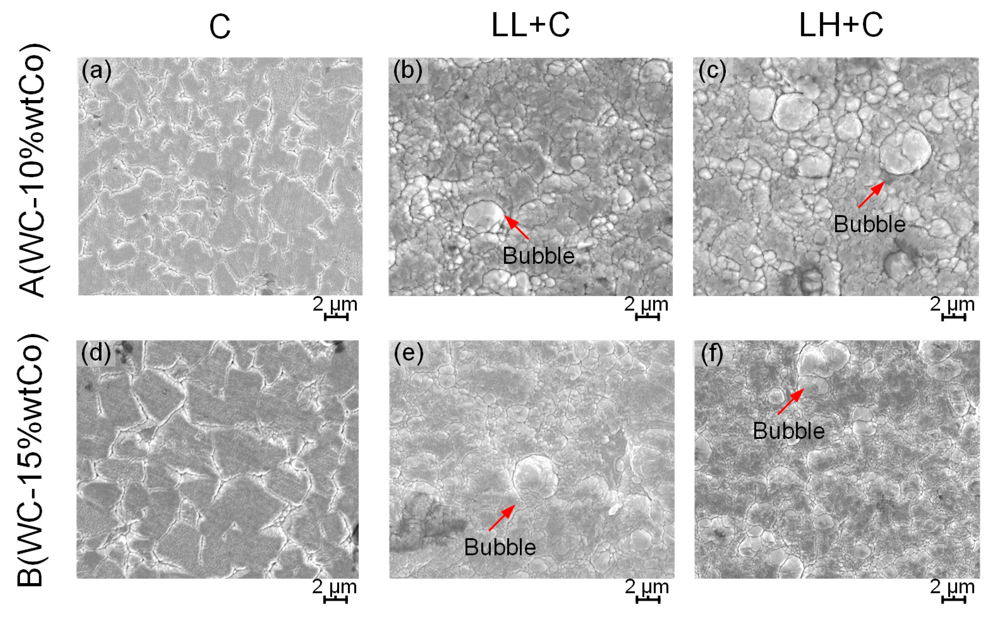
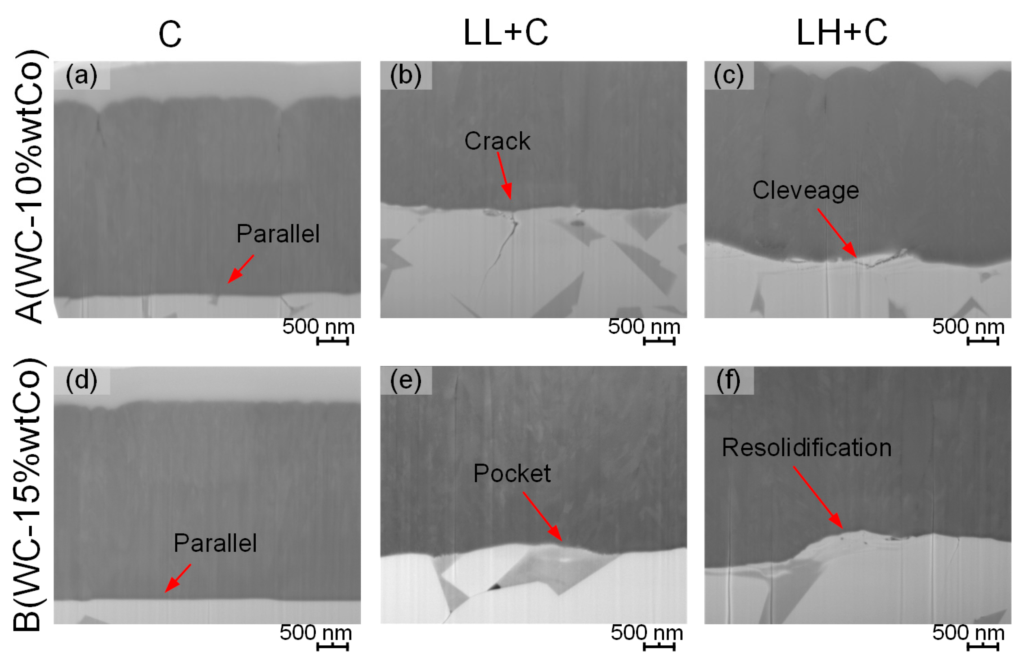
3.1.2. Morphological and Microstructural Changes: SEM-FIB Inspection

Morphological and microstructural changes were characterized using SEM-FIB [31]. In the non-lasered cases (Figure 1a,d), microstructural assemblages of the cemented carbide substrates were discerned, indicating a neat growth of the coating over them. Film morphology on the lasered substrates exhibited bubble-like features of different sizes, as shown in Figure 1b,c,e,f. These features were found on all the laser-ablated surfaces, and they were more pronounced on those surfaces processed with high laser energy. Meanwhile, such features appeared to be less representative in grade B than in grade A, indicating hindered formation with increasing binder content.
Cross-sectional inspection was carried out by means of FIB milling to characterize microstructural and coating–substrate interface features (Figure 2). It is evidenced that the ceramic layers grew with high parallelism on the polished (reference) surfaces (Figure 2a,d). Meanwhile, on the laser-ablated surfaces, the coatings developed on the substrate profile, and thus inherited the corresponding surface topographical features.
Detailed information about microstructural changes induced by laser near the coating–substrate interface is given in Figure 3. Different from the scenario found in the reference conditions (Figure 3a,d), it may be discerned that some damage was induced by laser ablation, including transgranular cracks running both perpendicular and parallel to the interface, as well as resolidification-like heterogeneities (e.g., Figure 3b,c,e,f). However, these changes were mostly localized within the substrate subsurface, at a very shallow depth (less than 1 µm). In this regard, the metallic binder was found to be more susceptible to laser ablation than the carbide grains, and thus excessive ablation of the binder left some pocket-like structures on the surface (Figure 3e). These areas have minuscule depths, and they could be partly responsible for the increased surface roughness obtained in these cases. The affected layers were thicker on the surface processed with high laser energy, promoting more resolidification of molten material (Figure 3e,f).

3.2. Mechanical Integrity Assessment

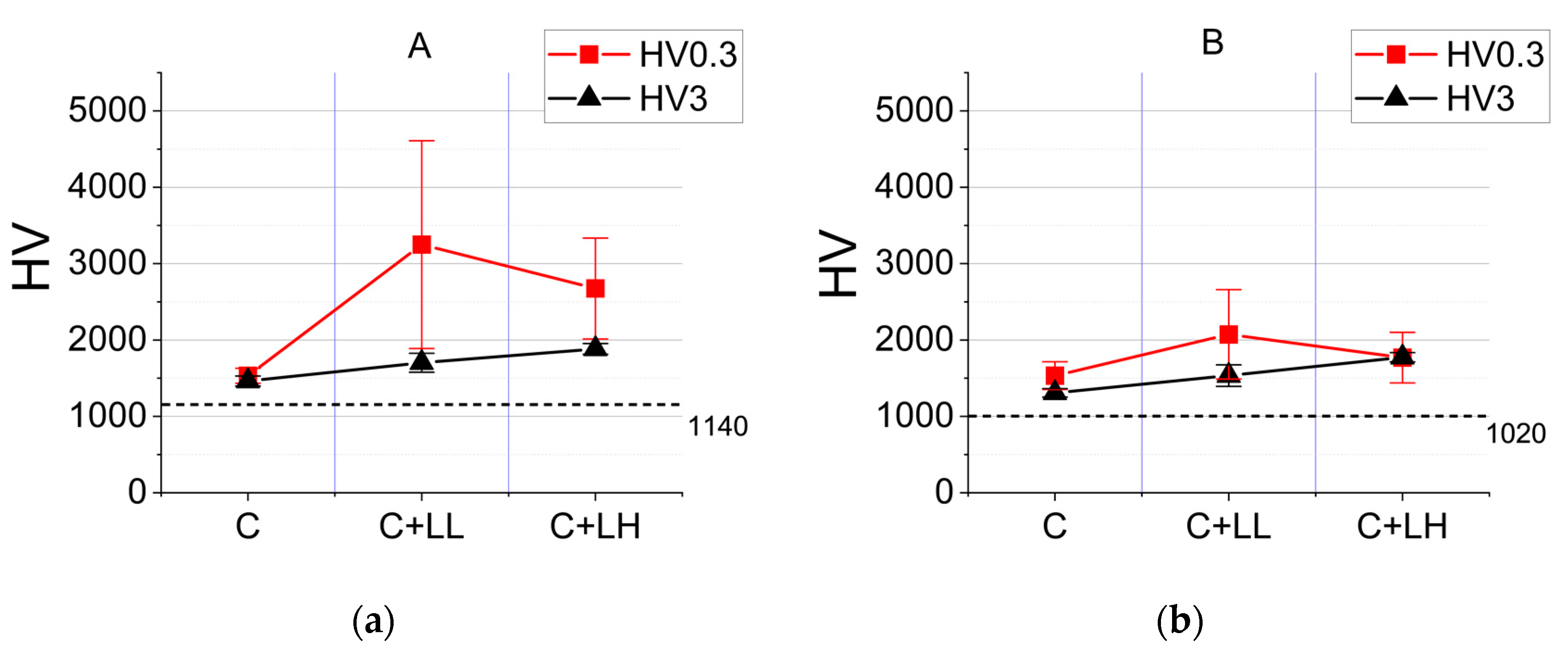
3.2.1. Indentation Contact Response: Vickers Hardness

The results of the Vickers hardness tests are compared in Figure 4. Coating deposition improved surface hardness for both cemented carbide grades, as compared to the bulk ones. Moreover, laser-processed and coated surfaces were hardened more than those exclusively coated. However, measured hardness values for both grades varied, depending on the applied load. In general, and as expected, the measured microhardness (HV0.3) values were greater than the macrohardness (HV3) ones.
Although the microhardness (HV0.3) values were expected to involve the intrinsic and higher load-bearing capability of the deposited coatings, the interface conditions could have an impact on the obtained results. In this regard, it is observed that the discrepancy between HV0.3 and HV3 values was more pronounced on the surfaces processed with low laser energy, as compared to those processed with high energy. This could be taken as an indicator that better surface finishing was achieved by the low-energy laser beam. Under the same surface finishing conditions, the difference in the measured hardness using the two applied loads, HV0.3 and HV3, should be the same on the same cemented carbide grade. On the contrary, the change in the measured hardness differences induced by the applied loads could indicate different surface finishing conditions. A ‘bad’ surface finishing may result in rough and fragile surface conditions weakening the HV0.3 measurement more than the HV3 measurement under the normal load, HV0.3. Based on the idea, the more pronounced discrepancy could indicate a better surface finish using low laser energy. On the one hand, this led to moderate ablation, as it was able to remove the binder exclusively, but not the surrounding carbide grains. Such slightly unbalanced ablation between binder and carbides resulted in a localized agglomeration of ceramic particles on the surface, and accordingly an increase in surface hardness [26,32]. On the other hand, both binder and grains were simultaneously ablated by the high-energy beam; thus, the high-energy beam could induce more pronounced material removal that may have resulted in a more ‘damaged’ interface. A more ‘damaged’ interface turned out to be less effective for carrying the imposed load during indentation. As a result, selective laser ablation of the binder with moderate energy may be pointed out, regarding surface integrity and enhanced hardness in the laser-coating system, as the most suitable option of the ones studied. From this perspective, hardening was found to be enhanced in grade A, as compared to grade B, as a lower binder content was more beneficial for the formation of contiguous carbide agglomerates. The macroscale (HV3) hardness for both grades increased as the laser energy was increased. In these cases, the hardness values obtained were closer to the ones exhibited by the substrates, indicating that the indenter was now able to penetrate the coating layers; thus, the interface condition was less relevant for defining the resistance of the material against permanent deformation. Residual stresses, which can influence mechanical properties, might have been induced by thermal diffusion during laser ablation, and such influence may become more important as the laser energy increases [33]. However, the assessment of residual stress effects was outside the scope of this work.

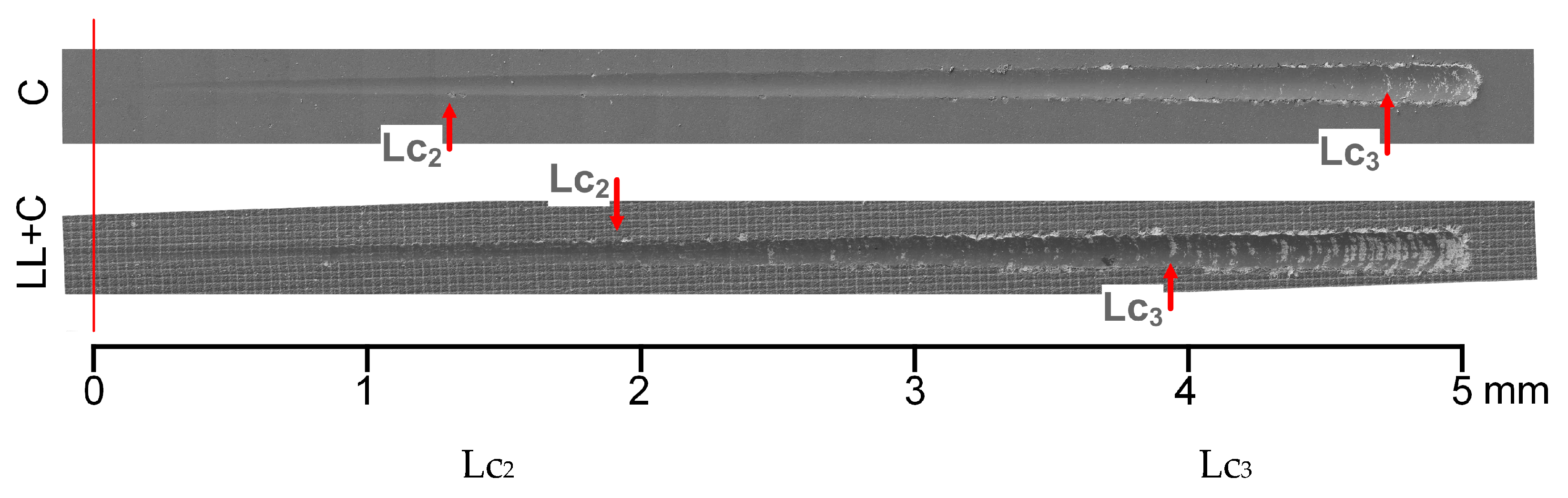
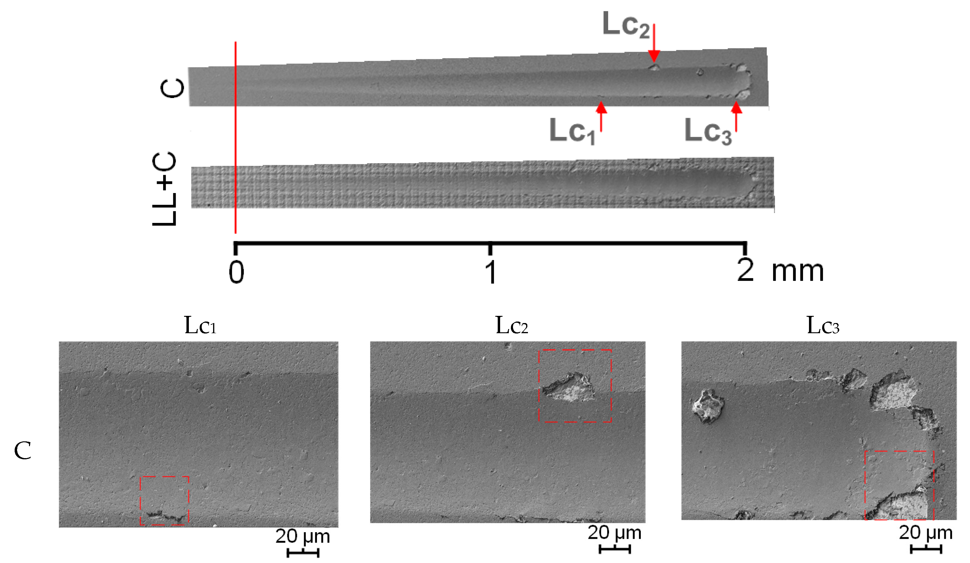
3.2.2. Sliding Contact Response: Scratch Testing

Taking into account the results attained, reported, and analyzed in the previous section, further investigation was limited to surface conditions involving ablation using low-laser energy exclusively. Accordingly, scratch tests were only conducted on surfaces processed by low-energy laser ablation and coating, i.e., LL + C, as well as the corresponding reference conditions, i.e., C (Table 2).

Frictional Performance: Coefficient of Friction

Friction is the force resisting the relative motion of two surfaces sliding against each other. Surface conditions may be effectively compared by evaluating frictional performance: the ratio between the normal force, Fn, and frictional (tangential) force, Ft, is defined as the coefficient of friction [34,35,36]. A low value of the coefficient of friction indicates a smooth sliding between the two contact surfaces. In this study, coefficient of friction (COF) values were obtained within the range of stable sliding, i.e., between 1 mm and 4 mm of the sliding distance. There, all the studied samples exhibited very similar average COF values, ranging from 0.056 to 0.063, and laser ablation did not induce any important impact on the frictional performance of the coatings during the scratch tests. The average COF values obtained during the scratch tests are given in Table 4.

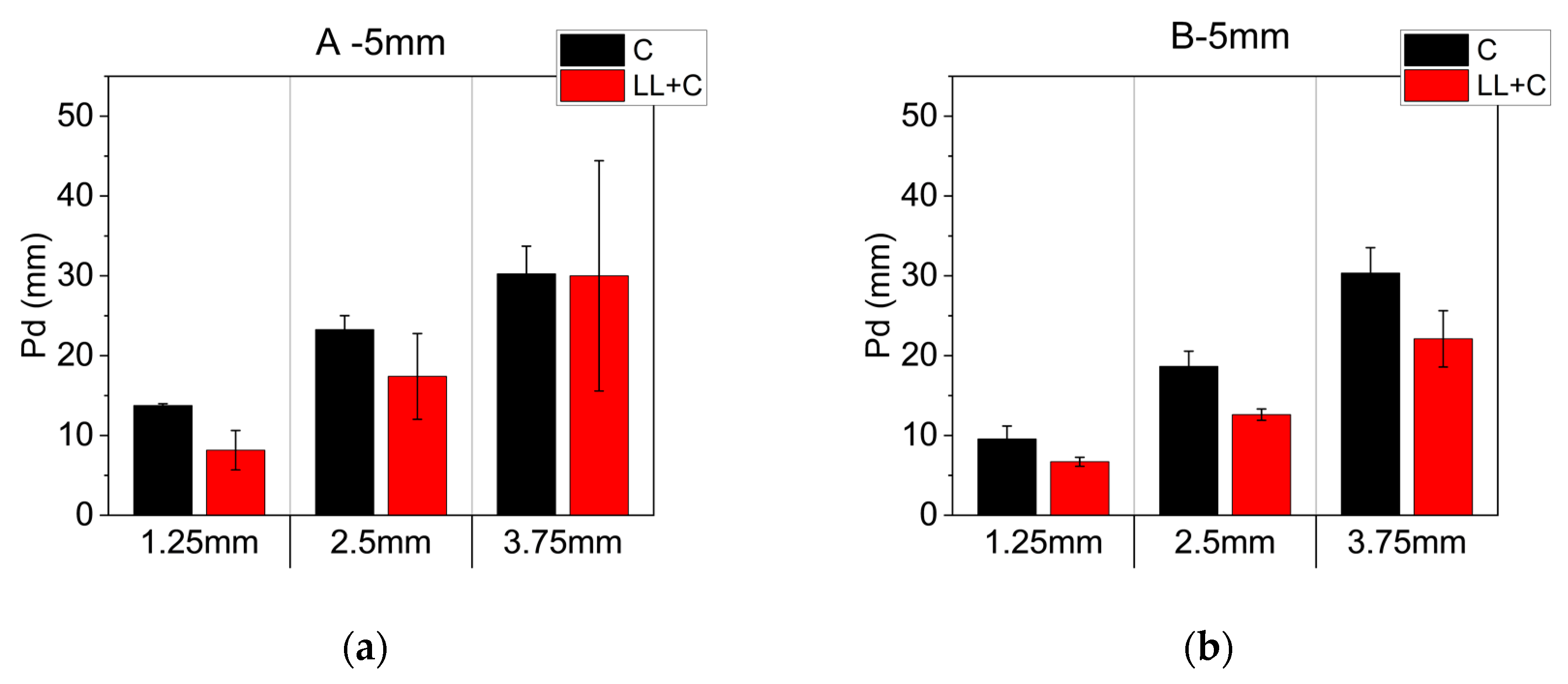
Indentation and Sliding Contact Performance: Penetration Depths (Pd) and Critical Loads (Lc)

Penetration depth was measured at three specific positions within the scratch tracks, corresponding to sliding distances of 1.25 mm, 2.50 mm, and 3.75 mm, and normal load values of 25 N, 50 N, and 75 N, respectively (Figure 5). The average values were calculated from experimental findings gathered in duplicated tests conducted under the same conditions. Independent of the microstructural assemblage of the two studied grades, less penetration occurred on the laser-ablated and coated surfaces, as compared to the reference ones. It allows us to point out that the indentation performance of the coated cemented carbides is effectively reinforced by the laser ablation of the substrate. Nevertheless, it should be highlighted that the penetration difference between the lasered and non-lasered conditions varied on the two grades, an experimental fact that could be affected by the synergistic effect of different factors such as hardness, carbide size, binder content, and binder mean free path, among others.
The sliding contact resistance of the laser-coated cemented carbide grades was assessed by determining, through SEM inspection, the critical loads for the emergence of specific damage events. In this regard, three standardized critical loads are defined in a scratch test, namely, Lc1, Lc2, and Lc3, as follows [37]:
  • First critical load, Lc1: linked to the initiation of forward chevron cracks within the scratch track;
  • Second critical load, Lc2: associated with the first failure event involving local or gross interfacial spallation; and
  • Third critical load, Lc3: defined by the first point where the substrate is visible along the center of the scratch track in a crescent that goes completely through the track, with gross interfacial spallation.
The positions of the critical loads on the scratch tracks (5 mm) were inspected by SEM and are accordingly marked in Figure 6 and Figure 7. Their values are also summarized in Table 5. Several observations may be highlighted. First, none of the conditions studied exhibited any forward chevron cracks within the scratch track; thus, the Lc1 could not be determined in any case. Second, local and gross interfacial spallation, both at the border and within a scratch track, were specific failure events identified for the non-laser-processed surface (C) for both grades, as well as for the laser-ablated one (LL + C) involving grade B. In these cases, the critical loads were higher for the reference A grade condition, as compared to that for the B grade condition. However, the laser-ablated condition (LL + C) for the latter exhibited higher values of Lc2 and Lc3 than the just coated one. Finally, the laser ablated condition (LL + C) involving grade A showed the best sliding contact response, as no damage or failure event was discerned for this condition within the scratch track. In general, these experimental findings allow us to state that laser ablation led to reinforced sliding contact resistance, this being more pronounced for the grade with lower binder content.

Reference Case Study (Large Increase in Load per Unit Distance)

A reference case study was conducted on the lasered and coated grade A (WC-10%wtCo) to document and analyze its indentation and sliding performances with a large increase in load per unit distance, i.e., over a sliding distance of 2 mm. Similar to the analysis done for the scratch test run over a length of 5 mm, penetration depths were measured, and critical loads on the selected scratch tracks (2 mm for this case study) were determined using SEM.
Average penetration depths were obtained at three specific sliding distances on the scratch tracks, i.e., 0.5 mm, 1.0 mm, and 1.5 mm, corresponding to normal loads of 25 N, 50 N, and 75 N, respectively (Figure 8). As for the 5 mm tests, it was found that penetrations were deeper in the scratch tracks for the reference conditions than for the laser-ablated ones. The positions of critical loads on the selected scratch tracks (2 mm) are marked in Figure 9. The positions and values of the critical loads are also summarized in Table 6. The scenarios observed were very similar to those found in previous scratch tests. The laser-ablated grade A did not show any obvious damage on the surface, and thus, no critical loads could be determined. Both scratch tests (5 mm and 2 mm) attest that the indentation and sliding performances of the coatings on grade A were reinforced by laser ablation.

Characteristic Wear Scenarios

Based on the inspection of the scratch tracks, characteristic wear scenarios were studied in the following cases, namely:
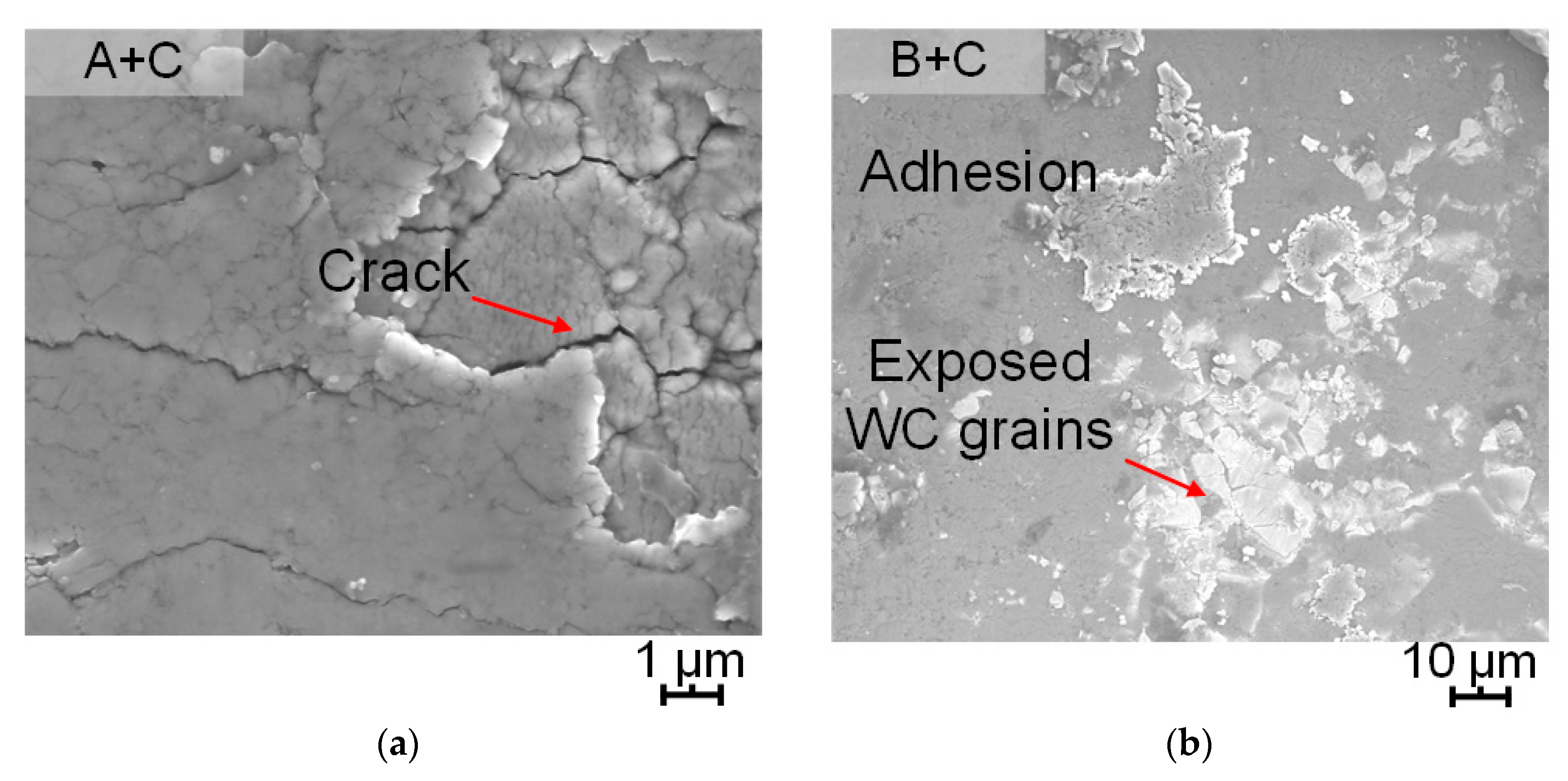
  • Case 0: Wear on the coated grades A (WC-10%wtCo) and B (WC-15%wtCo), without laser processing: A + C and B + C;
  • Case 1: Wear on the coated grades A (WC-10%wtCo), exclusively processed with low laser energy: A + LL + C;
  • Case 2: Wear on the coated grades B (WC-15%wtCo), exclusively processed with low laser energy: B + LL + C;
Case 0: A + C and B + C.
For both coated grades A and B, only minor damage, such as spallation along the track edge and subsequent substrate exposure, was found. The first damage appeared at the positions of 2.0 mm and 1.3 mm on grades A and B, respectively. Meanwhile, the first substrate exposure was discerned at a very late stage, close to the end of the track, i.e., at the positions of 4.9 mm and 4.7 µm in grades A and B, respectively (Figure 6 and Figure 7). The locations where the first substrate exposure was identified, in grades A and B, were examined in detail (Figure 10):
(1)
At the center of the scratch track of the coated grade A, cracking of the coating layer was observed (Figure 10a).
(2)
At a similar position on the coated grade B, exposed WC grains and adhered part of the broken coating layer were evidenced (Figure 10b).
Case 1: A + LL + C
Laser ablation not only delayed damage emergence, but also reduced its frequency on the coated grade A during the scratch tests. The coatings were, in general, able to resist the sliding movement without having any noticeable damage, like spallation or substrate exposure. Tiny changes were found in the scratch tracks due to pressing and sliding of the indenter. For instance, at the track end for the (A + LL + C) sample, the coating material was stacked in front of the indenter (Figure 11a).
Case 2: B + LL + C
Regarding grade B, some mild damage, such as stacking and cleavage of the layers either on the border or in the center of scratch tracks, together with more severe substrate damage, was found. Near the location where the first substrate exposure was discerned in the track (B + LL + C), the coating was completely stripped. Furthermore, the substrate was not only exposed but also damaged. As a result, WC grains were loosened and cracks nucleated (Figure 11b).

3.2.3. Comprehensive Evaluation of the Mechanical Integrity

Based on the results of the aforementioned measurements and characterization, a comprehensive evaluation of the mechanical integrity of the laser-ablated and coated cemented carbides was attempted. It was performed by comparing several key technical indicators, i.e., Vickers hardness (HV0.3, HV3), coefficient of friction (COF), penetration depth (Pd), and critical load (Lc2 and Lc3). Three scales, namely excellent (E), good (G), and moderate (M), were defined, and the results are given in Table 7. Based on the assessment conducted, it is found that:
(1)
Cemented carbide with low binder content, i.e., A (WC-10%wtCo) grade, generally performed better than the one with a high amount of metallic phase, i.e., B (WC-15%wtCo) grade.
(2)
Laser ablation in most cases improved the performance of the coated cemented carbides in terms of their indentation and sliding contact responses.
(3)
Laser ablation is commonly more beneficial to reinforce the mechanical properties of the low binder content grade, i.e., A (WC-10%wtCo), as compared to the other one studied, i.e., B (WC-15%wtCo).

4. Conclusions

In this work, the surface and mechanical integrity of two laser-processed and subsequently coated cemented carbides were evaluated using different characterization methods and approaches. Surface processing conditions varied with two different laser energy levels. From the results attained, the following conclusions may be drawn:
  • Laser ablation affects the surface integrity of cemented carbides, as it induces changes in the roughness, morphology, and microstructure of the substrate. However, these changes were rather minor, although they became slightly more important with increased laser energy.
  • Laser ablation promoted surface hardening on both coated grades, and the relative increase tended to be proportional to the applied laser energy. Although the micro- and macrohardness data followed similar trends, relative differences between their values were discerned, these being more pronounced on the surfaces machined by low laser energy.
  • The investigation just conducted on the grades processed with low laser energy allowed us to conclude laser ablation enhances both indentation and sliding contact responses. It was discerned from the findings of reduced penetration depth and higher critical load values for the emergence of specific damage/failure events, as compared to the behavior determined for the reference surface conditions. Within this context, the improvement in sliding resistance was more pronounced on the grade with lower binder content studied, i.e., A (WC-10%wtCo). Meanwhile, laser ablation had no significant influence on the frictional performance, as all the coated grades exhibited very similar COF values.

Author Contributions

Conceptualization, S.F.; methodology, S.F. and L.L.; investigation, S.F.; resources, L.L. and D.B.; writing—original draft, S.F.; writing—review and editing, L.L., Y.B.G. and D.B. All authors have read and agreed to the published version of the manuscript.

Funding

This research was funded by the Feodor Lynen Research Fellowship of the Alexander von Humboldt Foundation, by the Spanish Ministerio de Ciencia, Innovación y Universidades MICINN—FEDER (Spain) grant number PID2022-137274NB-C32, and by the German Research Foundation grant number INST 256/510-1 FUGG.

Data Availability Statement

The original contributions presented in the study are included in the article, further inquiries can be directed to the corresponding author.

Acknowledgments

The work leading to this publication was supported by the Feodor Lynen Research Fellowship of the Alexander von Humboldt Foundation. It was also partly funded by the Spanish Ministerio de Ciencia, Innovación y Universidades MICINN—FEDER (Spain) through grant number PID2022-137274NB-C32. The authors acknowledge funding for the FIB/SEM instrument by the German Research Foundation (INST 256/510-1 FUGG). The authors thank Hyperion Materials & Technologies for providing the samples and Flubetech S.L. for providing the PVD coating facilities.

Conflicts of Interest

The authors declare no conflict of interest.

References

  1. García, J.; Collado Ciprés, V.; Blomqvist, A.; Kaplan, B. Cemented carbide microstructures: A review. Int. J. Refract. Met. Hard Mater. 2019, 80, 40–68. [Google Scholar] [CrossRef]
  2. Wolfe, T.A.; Jewett, T.J.; Gaur, R.P.S. Powder synthesis. In Comprehensive Hard Materials; Elsevier: Amsterdam, The Netherlands, 2014; pp. 185–212. [Google Scholar] [CrossRef]
  3. Exner, H.E. Physical and chemical nature of cemented carbides. Int. Met. Rev. 1979, 24, 149–170. [Google Scholar] [CrossRef]
  4. Prakash, L. Fundamentals and General Applications of Hardmetals. In Comprehensive Hard Materials; Elsevier: Amsterdam, The Netherlands, 2014; pp. 29–90. [Google Scholar] [CrossRef]
  5. Yang, Q.; Zhang, P.; Lu, Q.; Yan, H.; Shi, H.; Yu, Z.; Sun, T.; Li, R.; Wang, Q.; Wu, Y.; et al. Application and development of blue and green laser in industrial manufacturing: A review. Opt. Laser Technol. 2023, 170, 110202. [Google Scholar] [CrossRef]
  6. Orazi, L.; Romoli, L.; Schmidt, M.; Li, L. Ultrafast laser manufacturing: From physics to industrial applications. CIRP Ann. 2021, 70, 543–566. [Google Scholar] [CrossRef]
  7. Shukla, P.; Waugh, D.G.; Lawrence, J.; Vilar, R. Laser surface structuring of ceramics, metals and polymers for biomedical applications. In Laser Surface Modification of Biomaterials; Elsevier: Amsterdam, The Netherlands, 2016; pp. 281–299. [Google Scholar]
  8. Bäuerle, D. (Ed.) Laser Processing and Chemistry; Springer: Berlin/Heidelberg, Germany, 2011; pp. 279–313. [Google Scholar]
  9. Etsion, I. State of the Art in Laser Surface Texturing. J. Tribol. 2005, 127, 248–253. [Google Scholar] [CrossRef]
  10. Hazzan, K.E.; Pacella, M.; See, T.L. Laser Processing of Hard and Ultra-Hard Materials for Micro-Machining and Surface Engineering Applications. Micromachines 2021, 12, 895. [Google Scholar] [CrossRef]
  11. Breidenstein, B.; Denkena, B.; Bergmann, B.; Krödel, A. Laser material removal on cutting tools from different materials and its effect on wear behavior. Met. Powder Rep. 2018, 73, 26–31. [Google Scholar] [CrossRef]
  12. Fang, S.; Llanes, L.; Bähre, D. Laser surface texturing of a WC-CoNi cemented carbide grade: Surface topography design for honing application. Tribol. Int. 2018, 122, 236–245. [Google Scholar] [CrossRef]
  13. Dumitru, G.; Lüscher, B.; Krack, M.; Bruneau, S.; Hermann, J.; Gerbig, Y. Laser processing of hardmetals: Physical basics and applications. Int. J. Refract. Met. Hard Mater. 2005, 23, 278–286. [Google Scholar] [CrossRef]
  14. Geiger, M.; Roth, S.; Becker, W. Influence of laser-produced microstructures on the tribological behaviour of ceramics. Surf. Coat. Technol. 1998, 100–101, 17–22. [Google Scholar] [CrossRef]
  15. Momma, C.; Chichkov, B.N.; Nolte, S.; von Alvensleben, F.; Tünnermann, A.; Welling, H.; Wellegehausen, B. Short-pulse laser ablation of solid targets. Opt. Commun. 1996, 129, 134–142. [Google Scholar] [CrossRef]
  16. Jahan, M.P.; Rahman, M.; Wong, Y.S. A review on the conventional and micro-electrodischarge machining of tungsten carbide. Int. J. Mach. Tools Manuf. 2011, 51, 837–858. [Google Scholar] [CrossRef]
  17. Bergs, T.; Chrubasik, L.; Petersen, T.; Klink, A.; Klocke, F. Experimental analysis of surface integrity of cemented carbides resulting from contemporary sinking EDM technology. Prod. Eng. 2019, 13, 511–517. [Google Scholar] [CrossRef]
  18. Schalk, N.; Tkadletz, M.; Mitterer, C. Hard coatings for cutting applications: Physical vs. chemical vapor deposition and future challenges for the coatings community. Surf. Coat. Technol. 2022, 429, 127949. [Google Scholar] [CrossRef]
  19. Bobzin, K. High-performance coatings for cutting tools. CIRP J. Manuf. Sci. Technol. 2017, 18, 1–9. [Google Scholar] [CrossRef]
  20. Gao, P.; Guo, Q.; Xing, Y.; Guo, Y. Structural, Mechanical, and Tribological Properties of Hard Coatings. Coatings 2023, 13, 325. [Google Scholar] [CrossRef]
  21. Bouzakis, K.D.; Michailidis, N.; Skordaris, G.; Bouzakis, E.; Biermann, D.; M’Saoubi, R. Cutting with coated tools: Coating technologies, characterization methods and performance optimization. CIRP Ann.—Manuf. Technol. 2012, 61, 703–723. [Google Scholar] [CrossRef]
  22. Byrne, G.; Dornfeld, D.; Denkena, B. Advancing cutting technology. CIRP Ann.—Manuf. Technol. 2003, 52, 483–507. [Google Scholar] [CrossRef]
  23. Fang, S.; Salán, N.; Pauly, C.; Llanes, L.; Mücklich, F. Critical Assessment of Two-Dimensional Methods for the Microstructural Characterization of Cemented Carbides. Metals 2022, 12, 1882. [Google Scholar] [CrossRef]
  24. Tarragó, J.M.; Roa, J.J.; Valle, V.; Marshall, J.M.; Llanes, L. Fracture and fatigue behavior of WC-Co and WC-CoNi cemented carbides. Int. J. Refract. Met. Hard Mater. 2015, 49, 184–191. [Google Scholar] [CrossRef]
  25. Fang, S.; Lima, R.; Sandoval, D.; Bähre, D.; Llanes, L. Ablation Investigation of Cemented Carbides Using Short-Pulse Laser Beams. Procedia CIRP 2018, 68, 172–177. [Google Scholar] [CrossRef]
  26. Li, T.; Lou, Q.; Dong, J.; Wei, Y.; Liu, J. Selective removal of cobalt binder in surface ablation of tungsten carbide hardmetal with pulsed UV laser. Surf. Coat. Technol. 2001, 145, 16–23. [Google Scholar] [CrossRef]
  27. Fang, S.; Hsu, C.J.; Klein, S.; Llanes, L.; Bähre, D.; Mücklich, F. Influence of laser pulse number on the ablation of cemented Tungsten Carbides (WC-CoNi) with different grain size. Lubricants 2018, 6, 11. [Google Scholar] [CrossRef]
  28. Claver, A.; Randulfe, J.J.; Palacio, J.F.; Fernández de Ara, J.; Almandoz, E.; Montalá, F.; Colominas, C.; Cot, V.; García, J.A. Improved adhesion and tribological properties of altin-tisin coatings deposited by dcms and hipims on nitrided tool steels. Coatings 2021, 11, 1175. [Google Scholar] [CrossRef]
  29. Dalibon, E.L.; Prieto, G.; Tuckart, W.R.; Brühl, S.P. Tribological behaviour of a hyperlox coating deposited over nitrided martensitic stainless steel. Surf. Topogr. Metrol. Prop. 2022, 10, 034003. [Google Scholar] [CrossRef]
  30. Yang, J.; Roa, J.J.; Odén, M.; Johansson-Jõesaar, M.P.; Esteve, J.; Llanes, L. Substrate surface finish effects on scratch resistance and failure mechanisms of TiN-coated hardmetals. Surf. Coat. Technol. 2015, 265, 174–184. [Google Scholar] [CrossRef]
  31. Fang, S.; Llanes, L.; Bähre, D. Wear characterization of cemented carbides (WC-CoNi) processed by laser surface texturing under abrasive machining conditions. Lubricants 2017, 5, 20. [Google Scholar] [CrossRef]
  32. Uhlmann, E.; Bergmann, A.; Gridin, W. Investigation on Additive Manufacturing of Tungsten Carbide-cobalt by Selective Laser Melting. Procedia CIRP 2015, 35, 8–15. [Google Scholar] [CrossRef]
  33. Denkena, B.; Breidenstein, B.; Wagner, L.; Wollmann, M.; Mhaede, M. Influence of shot peening and laser ablation on residual stress state and phase composition of cemented carbide cutting inserts. Int. J. Refract. Met. Hard Mater. 2013, 36, 85–89. [Google Scholar] [CrossRef]
  34. Trzepiecinski, T. A study of the coefficient of friction in steel sheets forming. Metals 2019, 9, 988. [Google Scholar] [CrossRef]
  35. Popov, V.L. Contact Mechanics and Friction: Physical Principles and Applications; Springer: Berlin/Heidelberg, Germany, 2010. [Google Scholar] [CrossRef]
  36. Blau, P.J. The significance and use of the friction coefficient. Tribol. Int. 2001, 34, 585–591. [Google Scholar] [CrossRef]
  37. ASTM C 1624-05; Standard Test Method for Adhesion Strength and Mechanical Failure Modes of Ceramic Coatings by Quantitative Single Point Scratch Testing. ASTM International Standards: West Conshohocken, PA, USA, 2005.
Figure 1. SEM micrographs showing surface morphology of the two cemented carbide grades processed by: (a,d) coating deposition only, (b,e) laser ablation with low energy followed by coating, and (c,f) laser ablation with high energy followed by coating.
Metals 14 00034 g001
Figure 2. SEM-FIB micrographs showing coating–substrate interface for the two cemented carbide grades processed by: (a,d) coating deposition only, (b,e) laser ablation with low energy followed by coating, and (c,f) laser ablation with high energy followed by coating.
Metals 14 00034 g002
Figure 3. Details of local microstructural characterization at the marked positions in Figure 2. An explanation of specific features highlighted in (af) is given in the text.
Metals 14 00034 g003
Figure 4. Comparison of the Vickers hardness for the two cemented carbide grades studied, as a function of surface modification condition: (a) A (WC-10%wtCo) and (b) B (WC-15%wtCo), with nominal values indicated by the dotted lines.
Metals 14 00034 g004
Figure 5. Average penetration depths (Pd) at specific positions within the scratch tracks for (a) A (WC-10%wtCo) and (b) B (WC-15%wtCo), processed under different conditions.
Metals 14 00034 g005
Figure 6. SEM images of the 5 mm scratch tracks for grade A (WC-10%wtCo) were processed with two different surface modification conditions, indicating positions associated with the emergence of specific failure events, and thus critical loads. Details of the discerned damage features are shown in high-magnification images. Scratch direction from left to right.
Metals 14 00034 g006
Figure 7. SEM images of scratch tracks for grade B (WC-15%wtCo) were processed with two different surface modification conditions, indicating positions associated with the emergence of specific failure events, and thus critical loads. Details of the discerned damage features are shown in high-magnification images. Scratch direction from left to right.
Metals 14 00034 g007aMetals 14 00034 g007b
Figure 8. Average penetration depths (Pd) at specific positions within the scratch tracks for A (WC-10%wtCo), processed under different conditions.
Metals 14 00034 g008
Figure 9. SEM images of the 2mm scratch tracks for grade A (WC-10%wtCo) were processed with two different surface modification conditions, indicating positions associated with the emergence of specific failure events, and thus critical loads. Details of the discerned damage features are shown in high-magnification images. Scratch direction from left to right.
Metals 14 00034 g009
Figure 10. Damage and failure events were identified: (a) cracking due to the crushing on the coated grade A, and (b) substrate exposure and adhesion on the coated grade B.
Metals 14 00034 g010
Figure 11. Damage and failure events identified: (a) stacking of the coating on grade A, and (b) complete removal of coating and substrate exposure on the laser-ablated and coated grade B.
Metals 14 00034 g011
Table 1. Nominal values of microstructural characteristics and basic mechanical properties of the studied cemented carbide grades (date from [23,24]).
GradeMean Carbide Grain Size (μm)Co (wt%)HV (GPa)KIc (MPa√m)
A2.33 ± 1.381011.4 ± 0.215.8 ± 0.3
B1.70 ± 1.081510.2 ± 0.117.0 ± 0.2
Table 2. Investigated surface processing conditions.
ConditionMachining Operation
CPVD-Coating (reference condition)
LL + CNanosecond Laser ablation with low energy + PVD-Coating
LH + CNanosecond Laser ablation with high energy + PVD-Coating
Table 3. Surface roughness resulting from the different processing conditions for the two cemented carbides under consideration.
SampleA (WC-10%wtCo) B (WC-15%wtCo)
CLL + CLH + CCLL + CLH + C
Ra (µm)0.030.410.680.040.480.56
Rz (µm)0.282.703.850.423.363.83
Table 4. Average values of COF were determined during scratch testing for the two cemented carbides and surface modification conditions studied.
SampleCOFσSampleCOFσ
A (WC-10%wtCo) C0.0570.003B (WC-15%wtCo)C0.0590.003
LL + C0.0560.005LL + C0.0630.005
Table 5. Values of critical loads determined on the selected scratch tracks (5 mm).
SampleLc1 (mm)F (N) at Lc1Lc2 (mm)F (N) at Lc2Lc3 (mm)F (N) at Lc3
AC--2.040.54.999.1
LL + C------
BC--1.325.84.794.5
LL + C--1.938.53.978.6
Table 6. Values of critical loads determined on the selected scratch tracks (2 mm).
SampleLc1 (mm)F (N) at Lc1Lc2 (mm)F (N) at Lc2Lc3 (mm)F (N) at Lc3
AC1.471.81.681.12.098.2
LL + C------
Table 7. Comprehensive evaluation within each coated cemented carbide grade *.
SampleIndenting ResponseSliding Response (5 mm)Results
HV0.3HV3COFPd at 50N (mm)Lc2 (mm)Lc3 (mm)
ACM (1532.0)M (1463.0)E (0.057)M (23.25)G (2.03)G (4.95)1E2G3M
LL + CE (3249.4)E (1702.2)E (0.056)G (17.4)E (-)E (-)5E1G0M
BCM (1533.6)M (1308.0)G (0.059)G (18.65)M (1.29)G (4.73)0E3G3M
LL + CG (2073.6)G (1533.8)M (0.063)E (12.60)G (1.93)M (3.93)1E3G2M
* Explanation of the evaluating indicators: E: excellent, G: good, M: moderate. Vickers hardness (HV0.3, HV3): the higher the value is, the better the performance is. Coefficient of friction (COF): the smaller the value is, the better the performance is. Penetration depth (Pd): evaluation was made according to the measured values at the normal load of 50 N, corresponding to the middle point of the scratch track, 2.5 mm, respectively. The smaller the value is, the better the performance is. Critical load (Lc2 and Lc3): the higher the value is, the better the performance is.
Disclaimer/Publisher’s Note: The statements, opinions and data contained in all publications are solely those of the individual author(s) and contributor(s) and not of MDPI and/or the editor(s). MDPI and/or the editor(s) disclaim responsibility for any injury to people or property resulting from any ideas, methods, instructions or products referred to in the content.

