Abstract
Inclusions are important phases affecting material properties in complicated ways. In this paper, a quantitative study of the addition of HfO2 inclusions to DZ125 nickel-based superalloys was performed. Experimental results showed that the introduction of HfO2 inclusions caused a loss of strength and ductility. The carbide morphology also changed significantly from skeletal-shaped to block-shaped, resulting in a remarkable discrepancy in the fracture behavior under quasi-in-situ tensile testing. The SEM dynamic observations showed that cracks were initiated from the skeletal carbides and almost failed to propagate into the matrix. In contrast, the damage behavior of block-shaped carbides also involved internal cracking but with a tendency to form interconnected microcracks during propagation. A crystal plasticity finite element model (CPFEM) method was further developed to study the stress/strain behavior during the deformation process, considering the crystal orientations and microstructure morphologies from the EBSD data. Those elastoplastic parameters were determined through nanoindentation experiments. Simulation results verified that blocky carbides produced a pronounced strain concentration at the interface of the carbides and matrix, thereby increasing the tendency of crack formation. This paper provides a fundamental understanding of the role of inclusions in material recycling applications.
1. Introduction
DZ125 nickel-based superalloys are a directional solidification alloy containing hafnium (Hf). They have been extensively used in the turbine blades of aircraft engines due to their exceptional performance [1,2]. However, the current utilization rate of superalloy castings is low, and a substantial number of recycled superalloys have been formed. Recycled superalloys introduce non-metallic inclusions (such as oxides or nitrides), and random inclusions can lead to an uneven microstructure in the material, generally resulting in a performance inferior to that of the original superalloy [3,4]. During the recycling of superalloys containing Hf, it is common to introduce HfO2 inclusions [5,6]. These non-metallic inclusions contribute to the reduced mechanical performance of superalloys, influencing the nucleation and propagation of cracks under tension or fatigue loading. A small number of inclusions have proved to be a key problem in the recovery of superalloys [7]. Therefore, understanding the effect of inclusions on the microstructure and mechanical properties of DZ125 nickel-based superalloys is crucial.
Extensive research has been conducted to understand the impact of non-metallic inclusions on the nucleation and propagation of cracks in superalloys. The impact of inclusions on superalloys varies significantly under different conditions. Factors such as temperature, loading method, size, and location all influence the failures induced by inclusions [8,9,10]. Hou et al. [8] studied the fracture mechanism of nickel-based superalloy K4750 under high cycle fatigue and found that the cracks originated from large-size inclusions. Zhang et al. [10] employed high-spatial-resolution digital image correlation (HR-DIC) and high-angular-resolution electron backscatter diffraction (HR-EBSD) techniques to investigate the nucleation and evolution processes of fatigue damage in polycrystalline nickel-based superalloys containing non-metallic inclusions. Jiang et al. [11] used similar observational methods and discovered that the inclusions’ geometric shapes contributed to increased local stress, and the concentration of local strain also promoted the nucleation of cracks.
However, the more severe detriment of inclusions to superalloys lies in their potential for contamination, by impacting the elemental concentration and microstructure of the alloy [12,13]. Although changes in carbide morphology due to inclusions have been observed in superalloys [14,15], very little research has associated these changes with the mechanical properties of superalloys. For carbides in superalloys, some studies have suggested that carbides play a role in reinforcing superalloys [16]. However, some researchers have even regarded carbides as a type of non-metallic inclusion because they can induce micro-void initiation and crack propagation [17,18]. This controversy is because carbides prevent dislocation movement and slip to strengthen superalloys; however, their brittle nature is the key factor causing fractures in superalloys. Carbides’ morphologies [19], types [20], and bonding strengths [21] affect the deformation and fracture behavior of superalloys. Therefore, carbides strongly affect the properties and damage fractures of superalloys.
The differences in material properties between inclusions and the superalloy matrix lead to localized stress/strain concentrations during the deformation process. Experimental methods have faced difficulty in observing stress/strain fields in microstructures, whereas crystal plasticity (CP) simulations can effectively study the distribution of plastic deformation stress/strain fields induced by inclusions [22,23]. Shenoy et al. [24] utilized CPFEM analysis to investigate inclusions’ roles in fatigue crack initiation in superalloys. The shape of inclusions and the orientation of neighboring grains influence the initiation of cracks. Liu et al. [25] identified that inclusions interfere with the plastic deformation of the alloy using CPFEM. This influence was more pronounced when inclusions were located at grain boundaries. However, the above-mentioned studies did not consider the actual morphology of the inclusions. In recent years, crystal plasticity finite element (CPFE) models based on experimentally obtained crystal orientations and morphologies have been widely applied. Jiang et al. [11] established a CPFEM model based on the actual morphology of inclusions, demonstrating that inclusions induce microcracks with the largest maximum shear stress. Zhang et al. [26] found that thermal expansion mismatches between inclusions and the matrix lead to localized strain under thermal loading. They established a CPFEM model that accurately described the distribution of strain fields and achieved good consistency with experimental results.
Based on the above analysis, research on the influence of inclusions on the microstructure and mechanical properties of DZ125 superalloys is insufficient. To investigate the impact of microstructural changes induced by inclusions on superalloy performance, we studied the effect of HfO2 powder inclusions on the microstructure and mechanical properties of DZ125 nickel-based superalloys, by quantitatively adding HfO2 powder inclusions (0–300 ppm) to the preparation process. A quasi-in-situ tensile test was used to observe the effect of carbide morphology changes produced by HfO2 inclusion on deformation behavior. A two-dimensional CPFE model was developed based on EBSD experimental data; it considered actual carbide crystal orientation and morphology. We used a numerical simulation to analyze the difference between the stress and strain fields during deformation.
2. Materials and Methods
2.1. Materials
Table 1 shows the composition of the DZ125 nickel-based superalloy used in this experiment. We quantitatively introduced HfO2 powder inclusions (0–300 ppm) to investigate the influence of HfO2 inclusions on the microstructure and mechanical attributes of DZ125 nickel-based superalloys. The method of adding HfO2 powder in this study was as follows: The original DZ125 superalloy was placed into the crucible and heated to 1520 °C. Then, HfO2 powder inclusions were added to the crucible and thoroughly stirred. The formed DZ125 superalloy was remelted once. Thus, the DZ125 superalloy used in this study is a recovery material. We directionally solidified the DZ125 superalloy with columnar grains aligned along the <001> orientation by a high-rate solidification (HRS) process with a 6 mm/min withdrawal rate. Finally, plate-shaped samples measuring 140 × 50 × 15 mm3 (length × width × height) were fabricated. Figure 1a depicts the DZ125 nickel-based superalloy cast that underwent a standardized heat treatment of 1180 °C/2 h + 1230 °C/3 h with air cooling (AC) + 1100 °C/4 h (AC) + 870 °C/20 h (AC). To ensure that experiments held comparative value and to eliminate microstructural changes arising from differences in solidification rates during the directional solidification process, we extracted the tensile specimens used for data comparison in this study from the lower section of the plate-shaped samples. Figure 1b depicts the schematic of the sampling procedure with the tensile specimens, and the locations for morphology observation are essentially identical.

Table 1.
Chemical composition of the original alloy used in this study (wt. %).
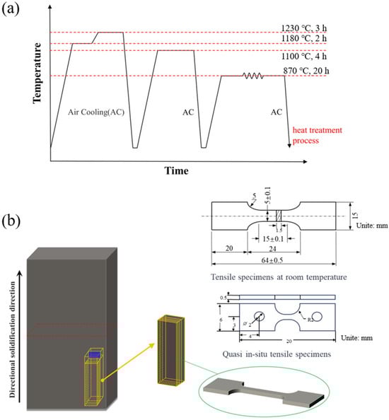
Figure 1.
(a) Process flowchart for the heat treatment of DZ125 nickel-based superalloy and (b) dimensions of the tensile specimens and schematic illustration of the sampling process.
For sample preparation via the standard metallographic procedure, a solution of 5 g CuCl2 + 100 mL HCl + 100 mL C2H5OH was used for etching for 15 s. Microstructures were observed using scanning electron microscopy (SEM, KSM-7610FPlus, JEOL, Tokyo, Japan) equipped with energy-dispersive X-ray spectroscopy (EDS, KSM-7610FPlus, JEOL, Tokyo, Japan) to determine carbides’ chemical compositions. Additionally, electron backscatter diffraction (EBSD, JSM-7001F, JEOL, Tokyo, Japan) was employed to analyze the observed surface orientations following vibratory polishing.
2.2. Conventional Tensile Testing and Quasi-In-Situ Tensile Testing
Conventional tensile tests were conducted to evaluate the mechanical properties of the samples using a universal testing machine. Tensile specimens were prepared according to standard specifications. The direction of room-temperature tensile testing was aligned parallel to the direction of directional solidification. Conventional tensile testing was conducted on a GNT200 universal testing machine, and Figure 1b illustrates the dimensions of the tensile specimens. The tensile rate was set to 0.00025/s until the onset of yield, and 6 mm/min afterward. To further comprehend the influence of carbide morphology alterations induced by HfO2, we conducted quasi-in-situ tensile tests to investigate inclusions’ influence on plastic deformation behavior. Quasi-in-situ tensile tests were conducted using a Zeiss Gemini EM300 scanning electron microscope equipped with a micro-tensile testing system. This setup allowed us to observe the microstructural evolution and damage behavior during the deformation process. All specimens were tested for failure, and fracture surface analysis was performed to determine the point of failure initiation. Nano-hardness tests were performed using an Agilent G200 nano-indenter tester following the GB/T 22458-2008 standard [27]. This comprehensive testing approach facilitated the assessment of DZ125 superalloys’ mechanical properties, microstructural changes, and plastic deformation behaviors under different conditions.
2.3. Crystal-Plasticity-Based Constitutive Model
We used a viscoplastic phenomenological model with a spectral solver within the framework of DAMASK to simulate the distribution of carbide morphologies in relation to fracture behavior and strain/stress fields. The constitutive equations of this model are briefly introduced in references [28,29], as follows: The total deformation gradient is decomposed into an elastic part and plastic part through a multiplicative decomposition as follows:
where represents the elastic deformation induced by lattice rotation and stretching, and denotes the plastic shear deformation caused by dislocation slip. The plastic velocity gradient induced by dislocation slip can be expressed as
where α denotes the slip system; is the shear strain rate of slip system α; and represent the slip direction and normal direction of the slip plane, respectively; and N is the total number of slip systems. can be defined by a simple rate-dependent power-law relation, as
where is the reference shear strain rate, and represent the resolved shear stress and critical resolved shear stress, and m is the strain rate sensitivity index. The evolution of is characterized by the hardening rate, which is given as follows:
The above equation describes the interactive behavior of different slip systems. Here, hαβ is the slip-hardening matrix; it is expressed as follows:
Therefore, the critical resolved shear stress of the α slip system can be derived as
where and are the resolved shear stress and critical resolved shear stress of slip system β, and and a are slip hardening parameters. Here, indicates the interaction parameters of slip systems, it is 1.0 and 1.4 for coplanar and non-coplanar slip systems, respectively.
3. Experimental Results
3.1. Microstructure Changes
For the DZ125 superalloy without HfO2 addition, MC-type carbides primarily exhibited a skeletal morphology, as shown in Figure 2a. Studies have indicated that such skeletal carbides do not adversely affect the superalloy’s performance and may instead reinforce them [30]. With the addition of HfO2 inclusions, the MC carbide morphology transformed, as shown in Figure 2c, and the proportion of blocky carbides gradually increased in certain regions. However, the addition of HfO2 did not significantly alter the γ′/γ phase, as shown in Figure 2b,d. These results are consistent with previous research [31,32]. Therefore, we defined the γ′/γ phase as the matrix [33], and the distribution of the γ′/γ phase was not considered in the subsequent simulation and test.
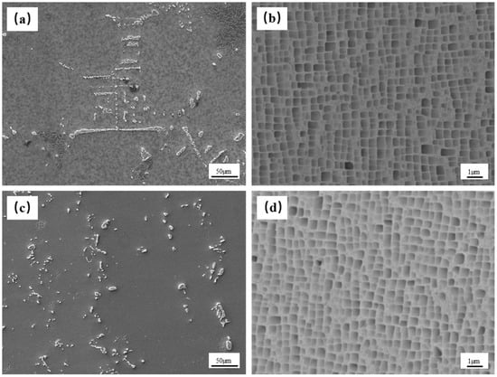
Figure 2.
SEM observation of the morphology of carbides and γ′/γ phase (a,b) without HfO2 inclusions and (c,d) with HfO2 inclusions.
Figure 3a,b shows the morphology and particle size distribution of the HfO2 inclusions powder, respectively. The size of the added HfO2 inclusions powder was mostly around 20 µm. The EDS elemental analysis indicated that HfO2 enrichment was observed at the center of the blocky carbides, as shown in Figure 3c. The nucleating effect of oxides has also been observed in other studies [34]. The EDS results indicated that blocky carbides show significantly higher Hf element content, as illustrated in Figure 3d,e.
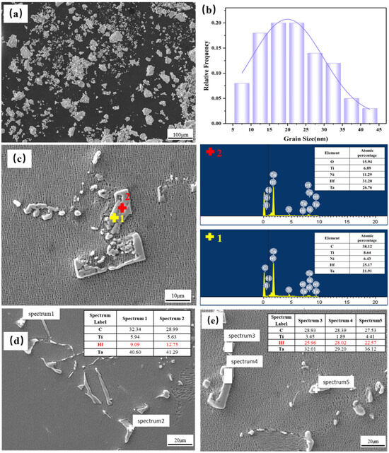
Figure 3.
(a) Morphology of HfO2 power added to the superalloys and (b) the particle size distribution of the added HfO2 powder, (c) presence of HfO2 observed at the center of the carbide. The EDS element analysis of (d) skeletal carbide and the EDS element analysis of (e) block carbide.
The EBSD was employed to examine carbides of different morphologies, providing crystal orientation and phase boundary information. Skeletal carbides primarily exhibited high misorientation of the phase boundary with the matrix, and their distribution was more concentrated. Moreover, the crystal orientations of skeletal-shaped carbides were nearly the same, as shown in Figure 4a,b. However, carbides with a blocky morphology had random crystal orientations. The statistical distribution of the misorientations of the phase boundary was quite dispersed and concentrated at larger angles, as shown in Figure 4c,d. This phenomenon arises from block-like MC particles, which contain a higher Hf content and exhibit greater MC/matrix interface mismatch [35]. Therefore, the phase boundary angles between blocky carbides and the matrix had a random distribution compared to the skeletal carbides.
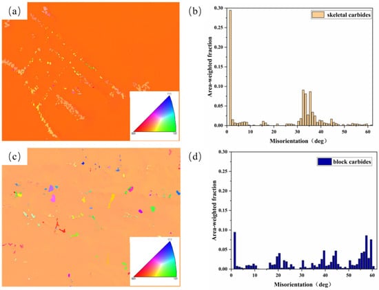
Figure 4.
(a,c) Crystal orientation maps (COM) of skeletal carbides and block carbides and (b,d) corresponding misorientation distributions of phase boundaries between the carbides and the matrix.
3.2. Mechanical Properties
Figure 5a depicts the engineering stress–strain curve. The results show that the tensile strength and elongation of DZ125 superalloy were decreased by adding HfO2 inclusions. The tensile strength did not decrease significantly with the addition of HfO2 inclusions but remained at about 1100 MPa. However, the elongation rate continued to decline at 100 and 200 ppm, increasing to a certain extent at 300 ppm, as shown in Figure 5b. This anomaly made us more interested in adding 300 ppm HfO2 inclusions. Therefore, we analyzed and compared the fractures for HfO2 contents of 0 and 300 ppm.
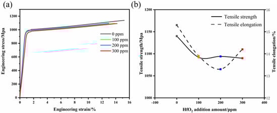
Figure 5.
(a) Engineering stress-strain curve of DZ125 alloy after adding HfO2 inclusion (0–300 ppm) for room-temperature tensile test and (b) tensile strength and elongation changes after tensile test.
Figure 6a,b presents the surface and secondary cracks of the SEM morphology near the fracture after tensile testing. The fracture surface of the specimen without HfO2 inclusions exhibited partial cleavage planes accompanied by numerous dimples observable under high magnification. This finding indicates that the fracture mode includes both brittle and ductile fractures. However, after the addition of 300 ppm HfO2 inclusions, extensive cleavage planes appeared at the fracture surfaces. Additionally, both the sizes and depths of the ductile dimples were smaller than in the DZ125 superalloy without HfO2 inclusions, as shown in Figure 6c,d. In the electron backscatter images depicted in Figure 6e,f, the white regions represent carbides and the gray areas correspond to the matrix phase. At the fracture surfaces of samples without inclusions, relatively intact skeletal carbides were observed. However, after 300 ppm HfO2 inclusions were added, the blocky carbides showed distinct cracking, with fractures tending to interconnect. An obvious cleavage platform can be observed around the broken blocky carbide, and it is inferred that this is the cause of the formation of the cleavage platform [36].

Figure 6.
Tensile fracture morphology for addition amounts of 0 ppm (a,c,e) and 300 ppm (b,d,f): (a,b) the macroscopic morphology, (c,d) the dimple morphology, and (e,f) the carbides at the fracture.
We utilized SEM to observe the morphology of secondary cracks on the fracture surface. As shown in Figure 7a,b, the cracks were mainly observed near the grain boundaries in samples without HfO2. In the samples with 300 ppm HfO2 inclusions, a noticeable increase in the density of secondary cracks was observed. In the sample without HfO2 addition, intact skeletal-shaped carbides were observed near the fracture surface, even in the region close to the fracture surface, as indicated by the white box in Figure 7c. However, in the sample with 300 ppm HfO2, the pulverization of block-shaped carbides was observed near the fracture surface, as indicated by the red box in Figure 7d.
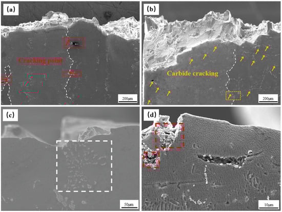
Figure 7.
Morphology of secondary crack section near tensile fracture under HfO2 addition of 0 ppm (a,c) and 300 ppm (b,d): (a,b) the macroscopic morphology and (c,d) the carbides at the fracture (The dotted white lines in (a,b) represent grain boundaries. The dashed box represents the crack at the grain boundary, where the location of the crack is indicated by an arrow, shown in red in (a) and yellow in (b)).
3.3. Influence of Carbide Morphology Distribution Characteristics on Plastic Damage Behavior
To observe carbides’ damage behavior under different morphologies during the tensile process more directly, we conducted quasi-in-situ tensile experiments. The quasi-in-situ tensile specimens of skeletal carbides were obtained from the DZ125 superalloy with an addition of 0 ppm HfO2 inclusions, while blocky carbides were obtained from the addition of 300 ppm HfO2 inclusions. Figure 8 illustrates the microstructure evolution of the skeletal carbide sample during quasi-in-situ tensile deformation. Considering the influence of random factors, we selected several positions to ensure a comprehensive analysis. In skeletal carbide samples, internal cracking of the carbides was the primary cause of secondary crack formation (marked by the yellow circle in Figure 8a,d,g). Microcracks were observed within the carbides during the tensile process and did not propagate into the matrix under increasing tensile strain. This trend indicated that the cracking induced by this carbide morphology was not the primary reason for the alloy’s failure (Figure 8c,f,i).
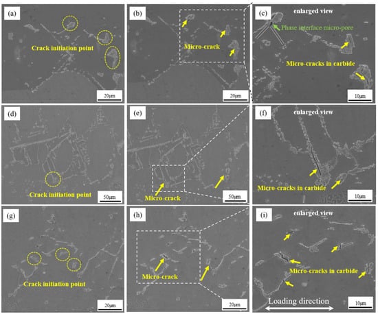
Figure 8.
The SEM maps of different regions of skeletal carbide specimens under tensile strain: (a,d,g) formation of microcracks, (b,e,h) microcrack propagation, and (c,f,i) locally magnified views of microcracks.
Figure 9 presents the initiation of micro-voids, the expansion of cracks, and the secondary crack morphologies after fracturing in the blocky carbide samples. The blocky carbides had more microcracks than the skeleton carbides. This may be due to the formation of blocky carbides on the HfO2 particles, which easily inherit the defects and loose areas in the oxide particles. Thus, the blocky carbides were more likely to break under stress, and they were easily connected to each other, resulting in the expansion of macroscopic cracks (as shown in Figure 9b,e,f), which ultimately reduced strength and ductility. Apart from initiating micro-cracks at the center of the blocky carbides, micro-voids at the interfaces between the carbides and the matrix were also significantly increased (marked by the green arrow in Figure 9c,f,i). The carbide itself and the bonding strength between the carbide and matrix are key factors affecting the tensile fracture behavior of superalloys [21]. This phenomenon showed that the bonding strength between the blocky carbides and the matrix is weaker than for skeletal carbides. Under tensile loading, micro-voids at the interface uniformly expanded towards the matrix and finally extended perpendicular to the direction of tension. Hence, the damage mechanisms in blocky carbides primarily involved internal cracking within the carbides and micro-voids at the carbide/matrix interfaces.
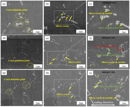
Figure 9.
The SEM maps of different regions of blocky carbide specimens under tensile strain: (a,d,g) formation of microcracks, (b,e,h) microcrack propagation, and (c,f,i) locally magnified views of microcracks.
We also observed the microstructure of two quasi-in-situ tensile specimens after elongation fracturing. As shown in Figure 10a, the crack propagation morphology at the fracture presented a fine sawtooth shape for the skeletal carbide, indicating that the skeletal carbide plays a hindering role. At the fracture of the blocky carbide specimen, all the blocky carbides were broken. The secondary crack density in blocky carbides was higher than in the skeletal carbide. The crack propagation path was more jagged because the matrix was the main carrier of plastic deformation. When the block carbide broke, the shape variable of the surrounding matrix increased. The plastic deformation produced obvious slip lines, and the slip direction was 45°, as observed in Figure 10b. The slip systems crossed each other, preventing the fault from moving, and finally producing the crack source. Crack initiation occurred along the slip line, so a 90° deflection of the crack growth path was observed [37]. This finding also explains the decreased sample strength but slight increase in elongation with the addition of 300 ppm HfO2.
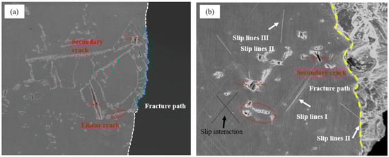
Figure 10.
The appearance of secondary cracks corresponding to the observed area after in-situ tensile fracturing, observed by SEM: (a) skeleton carbide sample and (b) blocky carbide sample (In (a), the white dashed line represents the crack propagation path in the matrix, the blue line represents the path near the skeletal carbide, and the yellow dashed line in (b) represents the crack propagation path in the matrix).
4. Discussion
4.1. The Evolution Behavior of Carbide Morphology
The DZ125 nickel-based superalloy contains various types of carbides, such as MC, M6C, and M23C6. MC-type carbides are predominantly enriched with Hf, Ta, and Ti, while M6C and M23C6 carbides contain higher concentrations of Cr, Mo, and W, mostly located near grain boundaries [38]. Different carbides significantly impact the alloy’s performance. M6C and M23C6 carbides contribute favorably to superalloy performance and are responsible for modifying grain boundaries and pinning dislocations. MC-type carbides undergo degradation at high temperatures, leading to the precipitation of secondary carbides. At lower temperatures, they provide sites for crack initiation [39]. Therefore, this study focused primarily on the role of MC-type carbides in the deformation process. Figure 3a shows that a HfO2 morphology was added to the superalloys in this study, with a size of approximately 20 µm. However, the presence of HfO2 of the same size was not observed in the alloy’s microstructure. Luca et al. [40] prepared superalloys via the addition of nano-sized HfO2 by laser-based powder-bed fusion and discovered that HfO2 undergoes reactions in the molten pool. However, the temperature in the directional solidification process did not reach the melting point of HfO2 in this study. Furthermore, HfO2 itself has a low Gibbs free energy, so it does not react with the precipitated phase in the melt. Therefore, it is inferred that the added HfO2 undergoes decomposition, and only tiny traces of HfO2 were observed at the center of the carbides. Heterogeneous nucleation leads to a change in carbide morphology.
4.2. Influence of Carbide Distribution and Morphology on Micro-Stress/Strain Distribution
Compared to the changes in carbide morphology produced by adding HfO2, blocky carbides were more prone to initiating crack nucleation. However, under normal circumstances, it appears that plastic damage is more likely to occur in the presence of harder precipitates that are more concentrated and larger in size. In this section, we used the EBSD experimental data considering carbides’ actual morphological characteristics and crystal orientations. Simulations were conducted to obtain differences in the stress/strain field distribution under tension for two carbide morphologies.
4.2.1. Determination of Model Parameters
The plastic behavior of most alloy metals can be approximated using power-law equations. The true stress–strain relationship can be expressed as follows:
In the equation, represents the strain during the plastic deformation stage, n signifies the strain-hardening exponent, and corresponds to the yield strength. Figure 11a illustrates the load–displacement curve from nano-indentation experiments conducted on carbides and the matrix interface. Table 2 shows the key parameters derived from the nano-indentation experiment. The matrix’s constitutive parameters (CPs) were derived using the inverse method and a combination of nano-indentation experiments and CPFEM simulations [41]. The material parameters were determined through a two-step process. Firstly, the true stress–strain curve of the alloy matrix was derived from nano-indentation experiments. Considering that the DZ125 superalloys used in this study comprised columnar grains, a single-phase columnar crystal model in Figure 11c was established to simulate the stress–strain curve. This simulated curve was then fitted to the stress–strain curve obtained from nano-indentation experiments to determine the constitutive parameters of the matrix. The crystal structure corresponding to the matrix was FCC; therefore, the simulation accounted for 12 × {111} <110> slip systems, as depicted in Figure 11b, and it demonstrated a favorable match with the computational results.
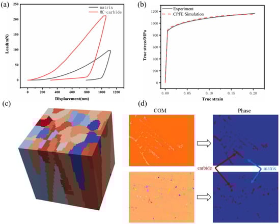
Figure 11.
(a) The load–displacement curve for the nanoindentation experiment on the matrix and carbides, (b) true stress/strain curve for the single-phase columnar crystal model compared to the experiment, (c) single-phase columnar crystal model, and (d) skeletal- and block-shaped carbide distribution models.
Table 2.
Key parameters for reverse-engineering the tensile true stress–strain curve from the nanoindentation curve of the single-phase matrix of the DZ125 nickel-based superalloy.
The Young’s modulus of the MC carbides was measured to be 433 GPa [42]. The reverse method mentioned above does not apply to determining the elastoplastic constitutive parameters of carbides. Therefore, the constitutive parameters for carbides were referenced from previous studies [43], and Table 3 presents the material constitutive parameters. Two 2D models were established, where the morphologies and crystal orientations of carbides are based on EBSD data, as illustrated in Figure 11d.
Table 3.
The material parameters in the phenomenological power-law model for matrix and carbide.
4.2.2. Influence of Morphological Distribution Characteristics on Stress/Strain Fields
Figure 12 presents the simulation results of strain (a1–a6) and stress fields (b1–b6) for distributing two carbide morphologies at tensile strains of 5%, 10%, and 15%. With increasing tensile strain, there were notable differences in the evolution of stress/strain fields for two microstructural features. Due to the disparity in hardness between the matrix and carbide, stress predominantly accumulates at the carbide and monotonically increases (Figure 12(a1–a6)). Compared to the blocky morphology distribution of carbides, skeletal carbides did not induce pronounced strain concentrations. At a strain level of 5%, due to the relatively low level of deformation, neither carbide morphology induced pronounced strain localization (Figure 12(b1,b4)). At a tensile strain of 10%, strain concentration points had already formed near blocky carbides, whereas they were almost absent near skeletal carbides (Figure 12(b2,b5)). This finding indicates that blocky carbides contribute to strain concentration. Upon reaching a strain level of 15%, comparative analysis revealed that the model with a blocky carbide morphology displayed pronounced strain inhomogeneity, primarily concentrated along the interface between the carbide and matrix (Figure 12(c2,c4)). Consequently, the interface strength between the carbide and matrix faced greater challenges during the stretching process. Linear stress concentrations were observed in the skeletal carbide morphology, consistent with the phenomenon of internal cracking observed during the in-situ stretching processes in skeletal carbides (marked by the purple line in Figure 12(c1)).
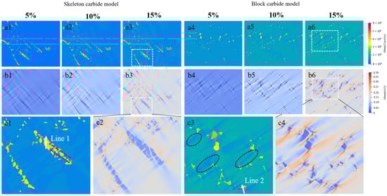
Figure 12.
(a1–a3,b1–b3,c1,c2) Skeletal carbide model and (a4–a6,b4–b6,c3,c4) blocky carbide model stress field and strain field maps at 5%, 10%, and 15% strain.
Comparing the accumulated shear slip distributions, Figure 13 shows that neither of the two carbide morphology distribution models could induce significant cumulative shear slip at a strain level of 5% (Figure 13(a1,a2)). As the strain increased to 10%, comparing the skeletal carbide model (Figure 13(b1,c1)) made it evident that a significant concentration of accumulated shear slip occurs first at the carbide–matrix interface in the block-shaped carbide model (marked by the yellow ellipse selection in Figure 13(b2)). Moreover, the concentration became more pronounced at a strain of 15% (indicated by the yellow arrow in Figure 13(c2)). Upon comparing the stress distribution map in the matrix under the 15% tensile strain condition, a phenomenon known as internal stress relaxation (ISR) was observed in localized regions of the matrix (marked by the black ellipse selection in Figure 12(c3)). The accumulation of dislocations leads to the destruction of obstacles under high-stress concentrations, resulting in significant stress relaxation. However, this phenomenon was not observed in the skeletal carbide model.
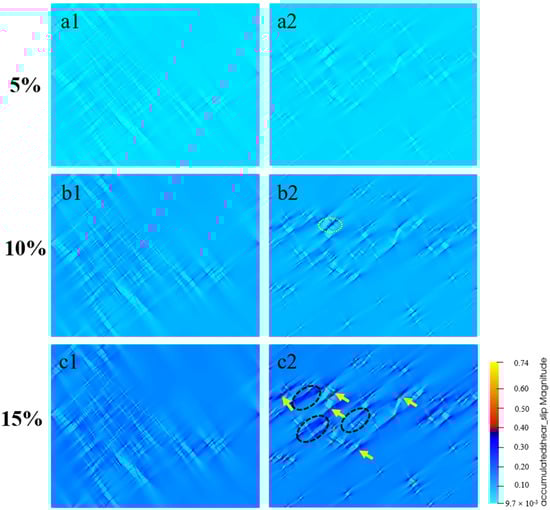
Figure 13.
(a1–c1) Skeletal carbide model and (a2–c2) blocky carbide model accumulated shear-slip distribution maps at 5%, 10%, and 15% strain.
Figure 14a,b depicts the evolution process of average strain and stress under different tensile strains. During the deformation process, the average strain of the blocky carbide morphology remained lower than that of the skeletal morphology. In contrast, there was little difference in the average strain within the matrix at low strains. The differences became obvious with increased tensile strain. Moreover, the blocky carbide model exhibited a higher rate under the increase of tensile strain. In Figure 14a, the average strain difference between the blocky carbides and the matrix was greater than that between skeletal carbides, which showed an increasing trend. This finding suggests that there is a more severe strain incompatibility between the carbides and the matrix in the blocky carbide model. The average stress within the matrix of the blocky carbide model was higher than that in the skeletal carbide model, which is consistent with the pattern observed in average strain, as depicted in Figure 14b. The average stress on the carbides demonstrated consistency under low tensile loads. However, with the increase in tensile strain, the average stress on the skeletal carbides was slightly higher than that in blocky carbides. This finding was attributed to the relatively concentrated distribution of skeletal carbides, which makes them more prone to inducing stress concentration overall.
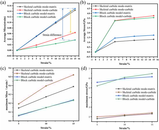
Figure 14.
Evolution of (a) average Mises (strain) and (b) average Mises (stress) with tensile strain. Evolution of (c) maximum strain and (d) maximum stress with tensile strain.
During plastic deformation, plastic damage is generally believed to occur in regions where the stress–strain concentration is more severe. As depicted in Figure 14c,d, the maximum stress/strain within the matrix is similar to that of the average stress/strain. However, the maximum stress/strain at the carbides exhibited a different variation trend. At a strain condition of 5%, the maximum stress/strain at the skeletal carbides surpassed that of the blocky carbides. However, the blocky carbides exhibited a higher rate of increase, ultimately resulting in higher maximum stress/strain values for blocky carbides. The reason behind this variation was that the size of carbides affects early stress–strain distribution. The distribution of skeletal carbides was more concentrated, subject to higher stress and strain concentrations. However, with loading progression, a noticeable accumulation of shear slip appeared near the blocky carbides (Figure 13(b2,c2)). The influence of phase boundaries on slip transfer behavior has been demonstrated as a crucial mechanism in modulating strain distribution [44]. Therefore, blocky carbides induce a greater strain concentration, making them crucial sites for initiating microporosity.
During the stretching process, the mechanical response and damage behavior were controlled by non-uniform strain and stress distributions. The diverse deformation behaviors of carbides with different morphologies indicate that stress concentration was the cause of fracture, while strain concentration was the potential cause of micro-void initiation. The simulation results indicated that the strain concentration in the skeletal carbide model was comparatively lower than in the blocky carbide model, reducing the risk of crack initiation and failure. The maximum strain/stress borne by blocky carbides was higher than in skeletal carbides, increasing the risk of unstable fracture. The observed comminuted fracture of blocky carbides at the fracture surfaces during in-situ tension testing also corroborates this viewpoint.
To qualitatively analyze the strain and stress distribution between the carbides and the matrix, the strain/stress curves passing through the carbides from the matrix were extracted. These findings helped summarize and analyze the influence of different carbide morphologies on strain/stress distribution. The white lines marked in Figure 12(c1,c3) offer a detailed assessment of different carbide morphologies’ influences on plastic deformation. Since carbides constitute the harder phase, the strain in the matrix was notably higher than in the carbides. From the curves, significant variations in strain and stress between the carbide/matrix interfaces are evident. Different carbide morphologies significantly impacted their own strain and stress distributions as well as those of the nearby matrix. Figure 15a shows that the strain rapidly decreases as the data points enter the interior of the carbides. The strain distribution within skeletal carbides was relatively uniform, whereas blocky carbides exhibited a noticeably uneven distribution with larger fluctuations. Moreover, the stress distribution revealed that blocky carbides could induce higher stress concentrations, as shown in Figure 15b. Therefore, during in-situ tensile experiments and fracture analyses, we observed that blocky carbides experienced more severe fractures, leading to the initiation of more micro-cracks.
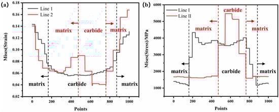
Figure 15.
Distribution characteristics of (a) Mises (strain) and (b) Mises (stress) along lines 1 and line 2.
5. Conclusions
The effect of quantitative addition of HfO2 inclusions on the microstructure and tensile mechanical properties of a DZ125 nickel-based superalloy was studied. The differences in plastic damage behavior under different carbides morphologies were clarified using tensile testing and the CPFEM method; the main conclusions are as follows:
- (1)
- The addition of HfO2 power inclusions produced heterogeneous nucleation sites and was conducive to the formation of blocky-shaped carbides, which resulted in the decrease of tensile strength and ductility.
- (2)
- The micro-voids initiated in skeletal carbides did not extend into the matrix, but the internal cracks and micro-void initiation at phase boundaries in blocky-shaped carbide samples increased the risk of micro-void connection, which was not conducive to ductility.
- (3)
- The skeletal carbide model exhibited a relatively uniform stress/strain distribution. In contrast, the blocky carbide model underwent larger internal stresses under tensile loading, resulting in a more severe and uneven strain distribution.
Author Contributions
Conceptualization, F.L.; methodology, D.W., J.S., C.X. and Y.W.; formal analysis, H.F.; investigation, H.F.; resources, F.L.; data curation, H.F.; writing—original draft preparation, H.F., F.L., D.W., J.S., C.X. and Y.W.; writing—review and editing, F.L. and Q.W. All authors have read and agreed to the published version of the manuscript.
Funding
This work was supported by the National Key Research and Development Plan (Grant No. 2022YFB3705000); the Foundation of Science and Technology on Advanced High Temperature Structural Materials Laboratory, AECC Beijing Institute of Aeronautical Materials, China (Grant No. 6142903220106); and the National Science and Technology Major Project (Grant No. J2019-Vl-0002-0115).
Data Availability Statement
The data presented in this study are available on request from the corresponding author. The data are not publicly available due to they form part of an ongoing study.
Conflicts of Interest
The authors declare no conflict of interest.
References
- An, W.; Utada, S.; Antonov, S.; Lu, S.; He, S.; Lu, F.; Zheng, W.; Li, L.; Cormier, J.; Feng, Q. Microstructural evolution and creep mechanism of a directionally solidified superalloy DZ125 under thermal cycling creep. J. Alloys Compd. 2023, 947, 169533. [Google Scholar] [CrossRef]
- An, W.; Utada, S.; Guo, X.; Antonov, S.; Zheng, W.; Cormier, J.; Feng, Q. Thermal cycling creep properties of a directionally solidified superalloy DZ125. J. Mater. Sci. Technol. 2022, 104, 269–284. [Google Scholar] [CrossRef]
- Gao, J.; Yang, S.; Yang, S.; Li, J.S.; Liu, W.; Zhao, M.J.; Wang, A.R. Evolution of inclusions in vacuum induction melting of superalloys containing 70% return material. J. Iron Steel Res. Int. 2023, 1–10. [Google Scholar] [CrossRef]
- Yang, S.; Yang, S.; Qu, J.; Du, J.H.; Gu, Y.; Zhao, P.; Wang, N. Inclusions in wrought superalloys: A review. J. Iron Steel Res. Int. 2021, 28, 921–937. [Google Scholar] [CrossRef]
- Li, Y.; Tan, Y.; Wang, D.; Li, P.; Chen, Z.; Zhao, J.; Qiang, J. Effect of trace impurity elements on the wettability and interfacial reaction between DZ125 alloy and ceramic shell. Corros. Sci. 2023, 221, 111370. [Google Scholar] [CrossRef]
- Xiao, J.; Xiong, Y.; Wang, L.; Jiang, X.W.; Wang, D.; Li, K.W.; Dong, J.S.; Lou, L.H. Oxidation behavior of high Hf nickel-based superalloy in air at 900, 1000 and 1100 °C. Int. J. Miner. Metall. Mater. 2021, 28, 1957–1965. [Google Scholar] [CrossRef]
- Zheng, L.; Zhang, G.; Gorley, M.J.; Lee, T.L.; Li, Z.; Xiao, C.; Tang, C.C. Effects of vacuum on gas content, oxide inclusions and mechanical properties of Ni-based superalloy using electron beam button and synchrotron diffraction. Mater. Des. 2021, 207, 109861. [Google Scholar] [CrossRef]
- Hou, K.; Ou, M.; Wang, M.; Hao, X.; Ma, Y.; Liu, K. Low cycle fatigue and high cycle fatigue of K4750 Ni-based superalloy at 600 °C: Analysis of fracture behavior and deformation mechanism. Mater. Sci. Eng. A 2021, 820, 141588. [Google Scholar] [CrossRef]
- Stinville, J.C.; Martin, E.; Karadge, M.; Ismonov, S.; Soare, M.; Hanlon, T.; Sundaram, S.; Echlin, M.P.; Callahan, P.G.; Lenthe, W.C.; et al. Competing modes for crack initiation from non-metallic inclusions and intrinsic microstructural features during fatigue in a polycrystalline nickel-based superalloy. Metall. Mater. Trans. A 2018, 49, 3865–3873. [Google Scholar] [CrossRef]
- Zhang, T.; Jiang, J.; Shollock, B.A.; Britton, T.B.; Dunne, F.P. Slip localization and fatigue crack nucleation near a non-metallic inclusion in polycrystalline nickel-based superalloy. Mater. Sci. Eng. A 2015, 641, 328–339. [Google Scholar] [CrossRef]
- Jiang, J.; Yang, J.; Zhang, T.; Zou, J.; Wang, Y.; Dunne, F.P.E.; Britton, T.B. Microstructurally sensitive crack nucleation around inclusions in powder metallurgy nickel-based superalloys. Acta Mater. 2016, 117, 333–344. [Google Scholar] [CrossRef]
- Mitchell, A. Nitrogen in superalloys. High Temp. Mater. Process 2005, 24, 101–110. [Google Scholar] [CrossRef]
- Yang, Y.H.; Yu, J.J.; Sun, X.F.; Jin, T.; Guan, H.R.; Hu, Z.Q. Effect of revert addition on microstructure and mechanical properties of M951 Ni-base superalloy. Mater. Sci. Eng. A 2012, 532, 6–12. [Google Scholar] [CrossRef]
- Yang, S.; Yang, S.; Liu, W.; Li, J.; Gao, J.; Wang, Y. Microstructure, segregation and precipitate evolution in directionally solidified GH4742 superalloy. Int. J. Miner. Metall. Mater. 2023, 30, 939–948. [Google Scholar] [CrossRef]
- Chen, X.C.; Shi, C.B.; Guo, H.J.; Wang, F.; Ren, H.; Feng, D. Investigation of oxide inclusions and primary carbonitrides in Inconel 718 superalloy refined through electroslag remelting process. Metall. Mater. Trans. B 2012, 43, 1596–1607. [Google Scholar] [CrossRef]
- Tang, Y.; Liu, J.; Cheng, H.; Yu, H.; Zhang, Y.; Zhu, J. Effect of hafnium on annealing twin formation in as-hot isostatically pressed nickel-based powder metallurgy superalloy. J. Alloys Compd. 2019, 772, 949–954. [Google Scholar] [CrossRef]
- Yang, X.; Dong, C.; Shi, D.; Zhang, L. Experimental investigation on both low cycle fatigue and fracture behavior of DZ125 base metal and the brazed joint at elevated temperature. Mater. Sci. Eng. A 2011, 528, 7005–7011. [Google Scholar] [CrossRef]
- Karamched, P.S.; Wilkinson, A.J. High resolution electron back-scatter diffraction analysis of thermally and mechanically induced strains near carbide inclusions in a superalloy. Acta Mater. 2011, 59, 263–272. [Google Scholar] [CrossRef]
- Zhang, Q. The Microstructure and Properties of Powder HIP ed Nickel-based Superalloy CM247LC. Doctoral Dissertation, University of Birmingham, Birmingham, UK, 2011. [Google Scholar]
- Song, X.; Wang, Y.; Zhao, X.; Zhang, J.; Li, Y.; Wang, Y.; Chen, Z. Analysis of carbide transformation in MC-M23C6 and its effect on mechanical properties of Ni-based superalloy. J. Alloys Compd. 2022, 911, 164959. [Google Scholar] [CrossRef]
- Rai, R.K.; Sahu, J.K.; Jena, P.S.M.; Das, S.K.; Paulose, N.; Fernando, C.D. High temperature tensile deformation of a directionally solidified nickel base superalloy: Role of micro constituents. Mater. Sci. Eng. A 2017, 705, 189–195. [Google Scholar] [CrossRef]
- Neu, R.W.; Dawkins, J.J.; Zhang, M. Applications of Crystal Plasticity in Contact Mechanics. In Proceedings of the International Joint Tribology Conference, Miami, FL, USA, 20–22 October 2008; Volume 43369, pp. 561–563. [Google Scholar]
- Chen, B.; Jiang, J.; Dunne FP, E. Is stored energy density the primary meso-scale mechanistic driver for fatigue crack nucleation? Int. J. Plast. 2018, 101, 213–229. [Google Scholar] [CrossRef]
- Shenoy, M.M.; Kumar, R.S.; McDowell, D.L. Modeling effects of nonmetallic inclusions on LCF in DS nickel-base superalloys. Int. J. Fatigue 2005, 27, 113–127. [Google Scholar] [CrossRef]
- Liu, P.; Jiang, H.; Dong, J.; Chen, Z. Effect of micron-scale nonmetallic inclusions on fatigue crack nucleation in a nickel-based superalloy. Int. J. Solids Struct. 2023, 279, 112368. [Google Scholar] [CrossRef]
- Zhang, T.; Collins, D.M.; Dunne FP, E.; Shollock, B.A. Crystal plasticity and high-resolution electron backscatter diffraction analysis of full-field polycrystal Ni superalloy strains and rotations under thermal loading. Acta Mater. 2014, 80, 25–38. [Google Scholar] [CrossRef]
- GB/T 22458-2008; General Rules of Instrumented Nanoindentation Test. Standards Press of China: Beijing, China, 2009.
- Roters, F.; Diehl, M.; Shanthraj, P.; Eisenlohr, P.; Reuber, C.; Wong, S.L.; Maiti, T.; Ebrahimi, A.; Hochrainer, T.; Fabritius, H.O.; et al. DAMASK–The Düsseldorf Advanced Material Simulation Kit for modeling multi-physics crystal plasticity, thermal, and damage phenomena from the single crystal up to the component scale. Comput. Mater. Sci. 2019, 158, 420–478. [Google Scholar] [CrossRef]
- Zhang, H.; Dong, X.; Wang, Q.; Zeng, Z. An effective semi-implicit integration scheme for rate dependent crystal plasticity using explicit finite element codes. Comput. Mater. Sci. 2012, 54, 208–218. [Google Scholar] [CrossRef]
- Zhang, J.; Zhang, Z.; Zhao, Z.; Zhong, Q.; Nie, B. Research on the healing behavior of the millimeter-sized cavity defect inside the superalloy by hot isostatic pressing. Mater. Lett. 2019, 235, 57–60. [Google Scholar] [CrossRef]
- Wu, Q.H.; Zhang, J.; Luo, Y.S. Composition and mechanical property of DD6 superalloy revert. In Materials Science Forum; Trans Tech Publications Ltd.: Stafa-Zurich, Switzerland, 2014; Volume 788, pp. 488–492. [Google Scholar]
- Guo, X.L.; Yu, J.B.; Li, X.F.; Hou, Y.; Ren, Z.M. Effect of nitrogen content on the microstructure and mechanical properties of a cast nickel-base superalloy. Ironmak. Steelmak. 2018, 45, 215–223. [Google Scholar] [CrossRef]
- Bandyopadhyay, R.; Sangid, M.D. Crystal plasticity assessment of inclusion-and matrix-driven competing failure modes in a nickel-base superalloy. Acta Mater. 2019, 177, 20–34. [Google Scholar] [CrossRef]
- Wang, J.; Wang, L.; Li, J.; Chen, C.; Yang, S.; Li, X. Effects of aluminum and titanium additions on the formation of nonmetallic inclusions in nickel-based superalloys. J. Alloys Compd. 2022, 906, 164281. [Google Scholar] [CrossRef]
- Chen, Q.Z.; Jones, C.N.; Knowles, D.M. Effect of alloying chemistry on MC carbide morphology in modified RR2072 and RR2086 SX superalloys. Scr. Mater. 2002, 47, 669–675. [Google Scholar] [CrossRef]
- Jiao, Z.; Wu, X.; Yu, H.; Xu, R.; Wu, L. High cycle fatigue behavior of a selective laser melted Ti6Al4V alloy: Anisotropy, defects effect and life prediction. Int. J. Fatigue 2023, 167, 107252. [Google Scholar] [CrossRef]
- Han, Q.N.; Qiu, W.; Shang, Y.B.; Shi, H.J. In-situ SEM observation and crystal plasticity finite el-ement simulation of fretting fatigue crack formation in Ni-base single-crystal superal-loys. Tribol. Int. 2016, 101, 33–42. [Google Scholar] [CrossRef]
- Zhang, J.; Zhao, Z.; Kong, Y.; Zhang, Z.; Zhong, Q. Crack initiation and propagation mechanisms during thermal fatigue in directionally solidified superalloy DZ125. Int. J. Fatigue 2019, 119, 355–366. [Google Scholar] [CrossRef]
- He, L.Z.; Zheng, Q.; Sun, X.F.; Guan, H.R.; Hu, Z.Q.; Tieu, A.K.; Lu, C.; Zhu, H.T. Effect of carbides on the creep properties of a Ni-base superalloy M963. Mater. Sci. Eng. A 2005, 397, 297–304. [Google Scholar] [CrossRef]
- De Luca, A.; Kenel, C.; Dunand, D.C.; Leinenbach, C. Effect of HfO2 dispersoids on the microstructure of a Ni-Cr-Al-Ti superalloy processed by laser-based powder-bed fusion. Addit. Manuf. Lett. 2023, 6, 100139. [Google Scholar] [CrossRef]
- Dao, M.; Chollacoop, N.; Van Vliet, K.J.; Venkatesh, T.A.; Suresh, S.J.A.M. Computational modeling of the forward and reverse problems in instrumented sharp indentation. Acta Mater. 2001, 49, 3899–3918. [Google Scholar] [CrossRef]
- Cedillos-Barraza, O.; Grasso, S.; Al Nasiri, N.; Jayaseelan, D.D.; Reece, M.J.; Lee, W.E. Sintering behaviour, solid solution formation and characterisation of TaC, HfC and TaC–HfC fabricated by spark plasma sintering. J. Eur. Ceram. Soc. 2016, 36, 1539–1548. [Google Scholar] [CrossRef]
- Csanádi, T.; Castle, E.; Reece, M.J.; Dusza, J. Strength enhancement and slip behaviour of high-entropy carbide grains during micro-compression. Sci. Rep. 2019, 9, 10200. [Google Scholar] [CrossRef]
- Ge, H.; Liu, G.; Zheng, S.; Yang, Y.; Liu, K.; Ma, X. Dislocation climbing dominated decomposition and fracture of carbides in a Ni-based superalloy. Acta Mater. 2023, 246, 118669. [Google Scholar] [CrossRef]
Disclaimer/Publisher’s Note: The statements, opinions and data contained in all publications are solely those of the individual author(s) and contributor(s) and not of MDPI and/or the editor(s). MDPI and/or the editor(s) disclaim responsibility for any injury to people or property resulting from any ideas, methods, instructions or products referred to in the content. |
© 2024 by the authors. Licensee MDPI, Basel, Switzerland. This article is an open access article distributed under the terms and conditions of the Creative Commons Attribution (CC BY) license (https://creativecommons.org/licenses/by/4.0/).