Article

The Potential of Cast Stock for the Forging of Aluminum Components within the Automotive Industry

1
SINTEF Manufacturing AS, 2830 Raufoss, Norway
2
Hydro Aluminium Primary Metal, 6600 Sunndalsøra, Norway
3
Raufoss Technology, 2830 Raufoss, Norway
4
SINTEF Industry, 7034 Trondheim, Norway
*
Author to whom correspondence should be addressed.
Metals 2024, 14(1), 90; https://doi.org/10.3390/met14010090
Submission received: 29 November 2023 / Revised: 7 January 2024 / Accepted: 9 January 2024 / Published: 11 January 2024

Abstract

:
In the automotive industry, there is a drive to reduce environmental impact, energy consumption, and costs related to the manufacturing of forged aluminum suspension components. The replacement of extruded stock with cast forging stock is one option that offers substantial potential for such savings. The casting technology, low-pressure casting (LPC), allows for production of high-quality cast forging stock with minimal surface segregation and smaller diameters than those achieved with traditional casting technologies. This study is a proof-of-principle, conducted to directly compare the microstructure and mechanical properties of LPC and extruded material after forging, through both generic and full-scale industrial forging trials. The results show the advantages of the cast material, including higher robustness against surface grain growth after forging and a positive correlation between mechanical properties, both strength and ductility and the introduction of plastic deformation. Overall, the work demonstrates how forged aluminum components produced from LPC forging stock can achieve mechanical properties and performance, on par with extruded forging stock, showcasing industrial relevance through the production of a safety-critical automotive component.

1. Introduction

The high-end OEMs have turned to forged aluminum alloys as their material of choice for chassis components such as suspension arms, steering knuckles, and wheel carriers, with a foreseen increase of about 5% by 2025 in Europe [1]. This is attributed to aluminum alloy’s desirable properties enabling the possibility of achieving high strength, corrosion resistance, and formability, combined with light weight and recyclability. Among manufacturing technologies, forging is an attractive process for producing high-precision components with a minimal need for post-processing operations. The process often involves several pre-shaping operations before the final forging step, which contributes to minimizing the material waste and ensuring optimal surface quality and optimal material flow in the die [2,3]. Forgings are particularly favored for safety-critical parts within the automotive industry due to their high structural reliability [4,5]. Traditionally, extruded aluminum alloys have been used as feedstock material, providing a fibrous microstructure with desirable properties such as strength, ductility, and high-cycle fatigue resistance [4,5]. However, a well-known challenge in forgings of extruded material is the growth of columnar coarse surface grains during post-forging solution heat treatment [6,7,8,9,10]. This poses a risk to fatigue performance and can initiate fracture during use [11,12]. The existing literature highlights the significance of optimizing the thermomechanical process to minimize such surface layer growth [9,13], exploring novel forging processes that introduce solution heat treatment prior to forging, followed by aging and providing a T5 temper in contrast to the traditional T6 temper (solution heat treatment and aging after forging). Zhao et al. [10], Gokchil et al. [13], Hua et al. [14] and Hu et al. [15], all explored the microstructure and mechanical properties achieved through such novel process routes for extruded AA6082 aluminum alloy. Their studies demonstrate that this state-of-the-art forging process route can yield high mechanical properties and a reduced thickness of the coarse surface grain layer. However, extrusion, as a step in the production chain, adds cost and contributes to the overall energy consumption of the manufacturing process. Research aimed to explore the possibilities of eliminating extrusion as part of the production route for forged aluminum components is therefore of high interest within the automotive industry.
By replacing extruded rods with cast rods as forging stock, a new, low-cost, and more efficient production route can be established, offering potential savings of 20% on a material level [6,16]. Despite its potentially large impact on the industry, the exploration of replacing extruded material with cast forging stock remains limited. Bobba et al. [17] conducted lab-scale compression trials on cast AA6061 aluminum alloy, evaluating forging behavior, microstructure, and hardness to determine optimal forging temperature. Birol and Ilgaz [8] and Birol et al. [18] documented the microstructural differences between cast and extruded AA6082 aluminum alloy in an industrially forged suspension component, emphasizing the uniform grain structure and superior surface quality of components forged from cast stock. Chang et al. [19] explored post-processing heat treatment methods, such as infrared heat treatment, to enhance the properties of an industrially forged car cantilever in T6 condition, reporting that cast AA6082 aluminum alloy exhibited slightly lower strength but higher ductility than the extruded material. Hosoda et al. [20] and Nakai and Itoh [21] evaluated the influence of strain rate on the microstructure and achieved properties after hot-forming of cast AA6061 aluminum alloy, showing a relationship between resulting grain structure and achieved properties such as strength and fracture toughness. Notably, data on mechanical properties such as strength and fatigue in forged components from cast stock is only found in some of the existing literature, with minimal overlap between the studies on alloy or experimental setup. There is also a clear need for additional research contributing to exploring the parameters influencing the microstructure and properties of forged components from cast material, as is established for extruded material.
Currently, the availability of cast forging stock in desirable dimensions is limited. This could be related to the high investment cost of a horizontal casting line, giving relatively low production volumes. Furthermore, cast material exhibits a segregation zone at the surface, which has a slightly different chemical composition compared to the core. This zone must be scalped off prior to forging, adding scrap and costs to the product. Addressing these challenges, a promising solution lies with the low-pressure casting (LPC) technology [22], developed and now implemented in production by Hydro Aluminium R&D. This LPC technology enables the production of small diameter cast billets (80 mm or wider) with high surface quality and low surface roughness. Notably, the surface segregation depth in LPC billets is significantly lower compared to those billets produced with traditional casting technologies [16]. Nunes et al. [23] provide a comparative analysis of low- and high-pressure casting technologies, highlighting the reduced tendency of defect formation in low-pressure casting technologies. While LPC material has primarily found application within extrusion, reportedly increasing yield and productivity [24], its potential in aluminum forging remains unexplored despite the improved quality and available dimensions.
The current study sought to explore the potential of LPC material as a viable option for aluminum forging through an industrial proof-of-principle study. The primary objective was to benchmark and directly compare the obtained microstructure and properties of the LPC material to those in a commercially available forged suspension component made from extruded forging stock. The work was performed as a collaboration between Hydro Aluminium Primary Metal, SINTEF and Raufoss Technology. The study is divided into two parts: generic forging trials and full-scale industrial forging trials. The industrial scale trials were performed by Raufoss Technology in their running production line, producing a front lower control arm (FLCA). The FLCA and the thermomechanical process are shown in Figure 1a,b, respectively. The FLCA production line included solution heat treatment prior to forging, providing a T5 condition, which is the current state-of-the-art within forging of extrusions [10,13,14,15]. In this forging process, pre-shaping via cross-wedge rolling (CWR) was an essential step. The effect of pre-forming prior to forging on the LPC material was thus also explored in this study during the generic forging trials. Overall, the work emphasizes the potential of LPC material, exploring both microstructure and mechanical performance including tensile and fatigue performance, which have been minimally reported in the current literature and providing direction for further process optimization and research needs.

2. Materials and Methods

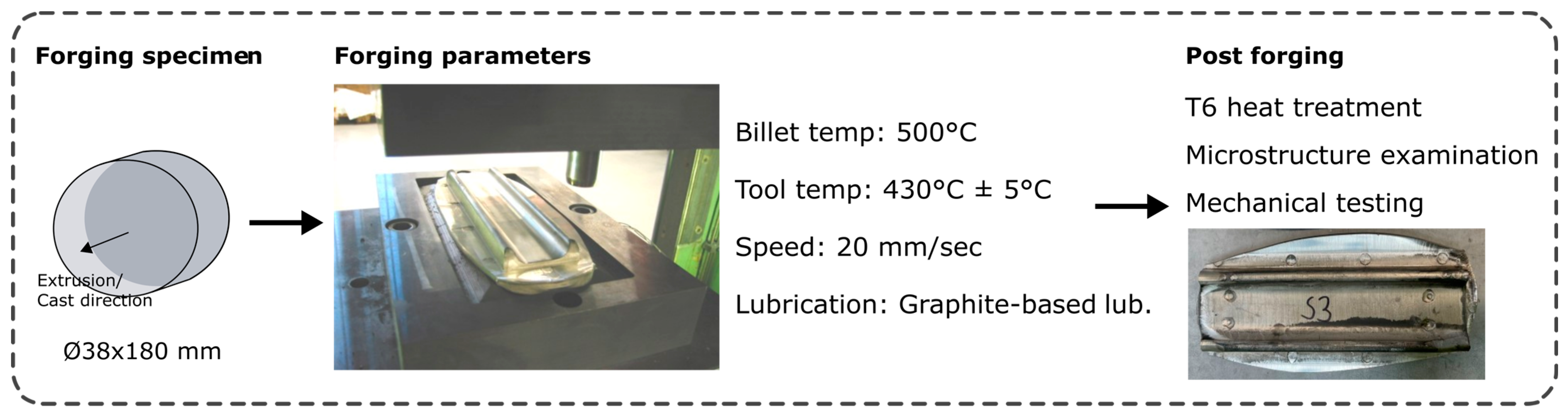
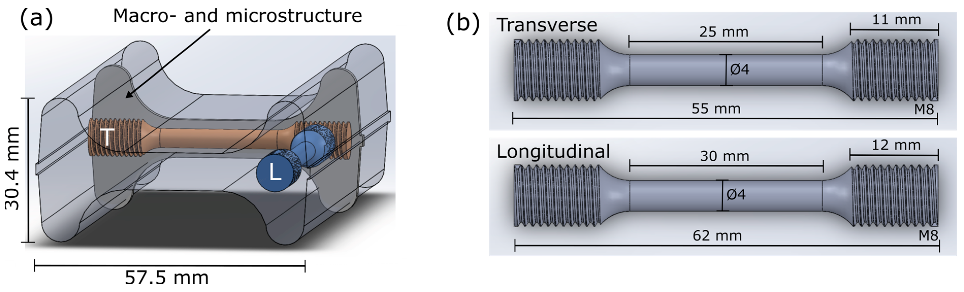
2.1. Generic Forging Trials

The material investigated in this work belongs to the AA6082 alloy group. For the generic forging trials, rods were prepared in three conditions:
  • As extruded: material provided by Raufoss Technology from their standard extruded forging stock.
  • As cast and homogenized: 90 mm LPC material was provided by Hydro Aluminium Primary Metal, produced at the Husnes plant. Homogenization was performed at 550 °C for 2 h, followed by rapid cooling in air.
  • Pre-formed cast: in this case, the homogenized LPC material was pre-formed via CWR by Raufoss Technology. The CWR component was taken out from the production line after CWR and cooled down to room temperature prior to extracting the required specimens for the forging trial.
For each material condition, specimens with the dimensions of 38 × 180 mm were prepared. For the extruded material, the specimen was collected from the center of the rod. For the as cast, two specimens were extracted side-by-side within the diameter of the cast billet. From the CWR component, a segment which had the required diameter of 38 mm (initial diameter reduction close to 53%) was used to extract the required forging specimen.
In total, five of each variant were forged in the generic forging trial. A schematic illustration of the generic forging trial procedure is shown in Figure 2, including images of the forged component. The forging stock was preheated to 500 °C, with a holding time of a minimum of 10 min (45 min total time in the oven). Then, the specimens were forged using a 1000 ton hydraulic press, with a tool temperature of 430 °C ± 5 °C and a forging speed of 20 mm/s. The billet and tool temperature were selected based on production parameters in the explored industrial production trial and common forging parameters utilized for aluminum in the literature and industry [4,7,10,13,16,20,21]. The forging speed was limited by the utilized hydraulic press.
After forging, the components were cooled in water followed by a post-forging heat treatment to T6, including solution heat treatment at 550 °C for 15 min at temperature, followed by water quenching and finally aging at 185 °C for 4 h in a pre-heated furnace. The specimens were stored at room temperature for 24 h after quenching prior to aging.
Tensile test specimens (according to ISO 6892-1 [25]) were extracted from the forged components in two different positions and directions as shown in Figure 3a, the longitudinal (L) and transverse (T) directions. The longitudinal direction was parallel to the initial extrusion and cast direction of the forging specimens. The dimensions of the tensile specimens are shown in Figure 3b. In total, three parallels in each direction were tested. The average results are presented, including the deviation among the obtained three values, indicated by ±.
The macrostructure of the forged components was evaluated via cutting out a cross-section, as indicated in Figure 3a, which was fine ground followed by etching in a caustic soda solution (3 kg NaOH in 45 L water) for 10 min. The microstructure was investigated on smaller sections that were mounted in epoxy followed by grinding and polishing according to standard metallographic procedures for aluminum. To reveal the microstructure and grain size, the polished cross-sections were anodized with Barkers Reagent (5% HBF4 in water, 20 V for 60 s). Images were obtained using stereo and optical microscopy (bright field and polarized light settings were used).

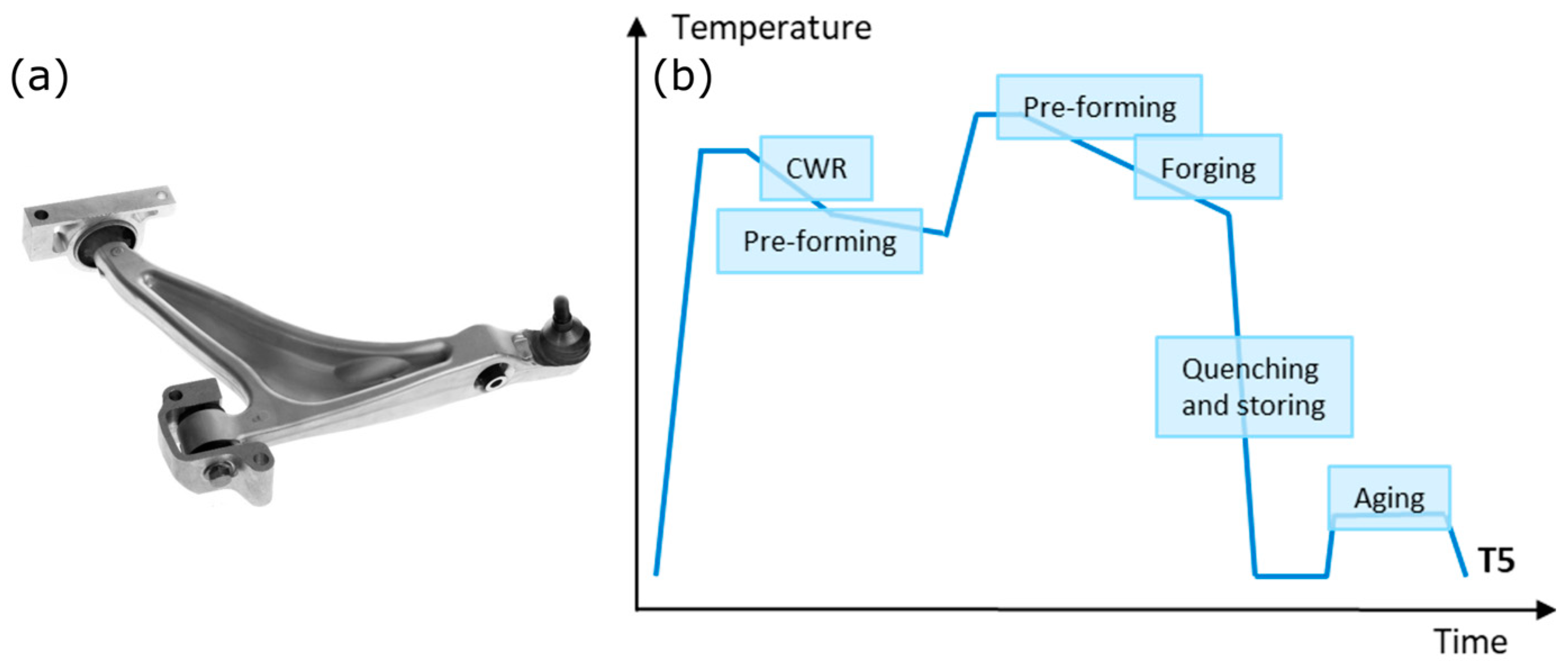
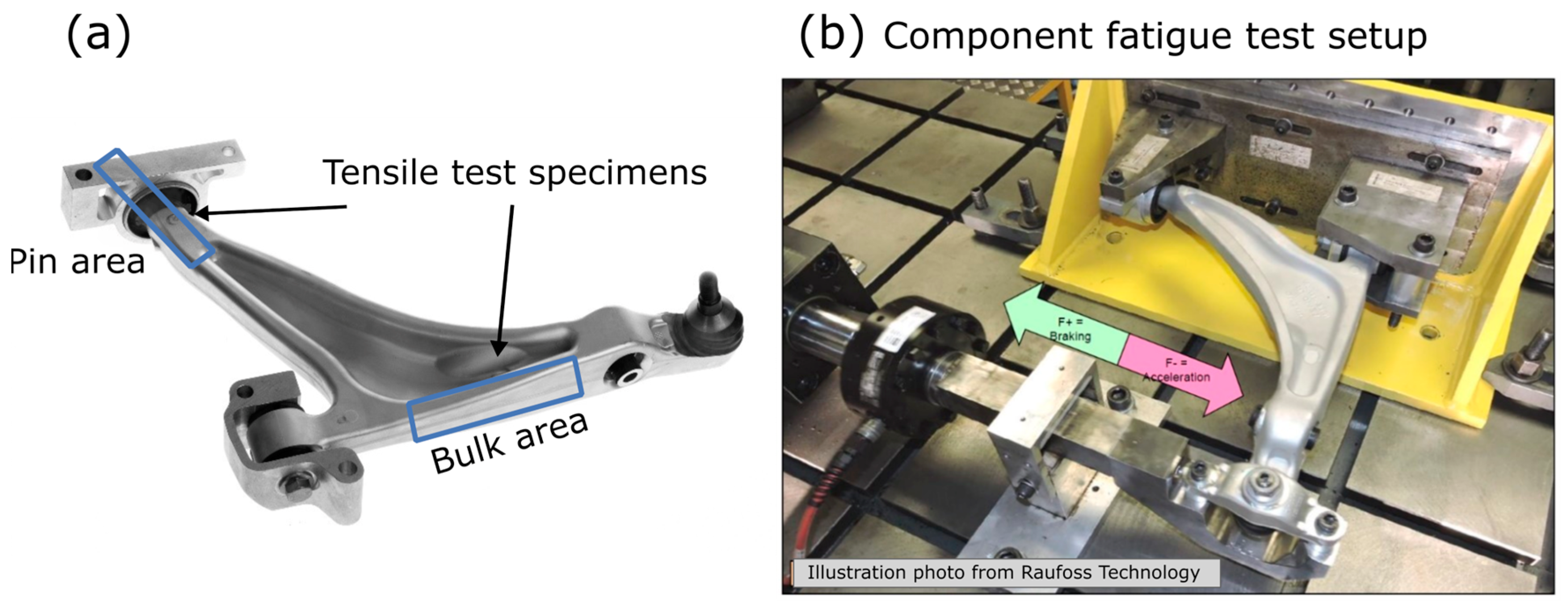
2.2. Full-Scale Production Trials of FLCA

FLCA with integrated ball joints, as depicted in Figure 1a, were forged by Raufoss Technology using the LPC forging stock (cast and homogenized, as introduced in Section 2.1). The production route involved several pre-forming steps before forging, as illustrated in Figure 1b. The process parameters were kept unchanged to directly compare and benchmark the final forged suspension component from the LPC stock with the standard suspension component made from extruded stock in the running production. In total, 25 FLCA were produced with LPC forging stock. Five were evaluated in as-produced T5 condition, aged using their in-house aging process after forging. Additionally, three FLCA underwent a post-forging heat treatment to achieve a T6 condition. The heat treatment included solution heat treatment at 560 °C for 15 min, followed by quenching, storage at room temperature for 24 h, and aging at 185 °C for 4 h in a preheated furnace.
Subsequently, all components were subjected to standard product quality control. The mechanical properties were assessed through tensile testing [25]. The positions of the extracted tensile test specimens are shown in Figure 4a, including specimens from the bulk area (standard position) and the pin area, both in longitudinal direction to the initial cast and extruded direction of the forging stock. The pin area of the FLCA corresponds to the section of the CWR component used as feedstock material in the generic forging trials, which represented the pre-formed cast forging stock. Tensile specimens were only extracted from the pin area for three selected components. Results for the FLCA produced from extruded forging stock were based on five randomly selected production trial test results from 2022. Additional testing of the pin area was conducted for one component. Macro and microstructure were evaluated following the same procedure as for the generic forging trials, as described previously. The grain size was estimated by measuring minimum 100 grains, using the obtained optical microscopy images.
The fully assembled FLCA produced with LPC forging stock, featuring integrated ball-joints and bushings, underwent in-house component fatigue testing using the setup shown in Figure 4b. The fully assembled component underwent single-axis cyclic fatigue, with forces of up to 28 kN until failure. Five FLCA were tested, and the results for three of those components are provided and compared to the currently established average for components produced with extruded forging stock.

3. Results

3.1. Generic Forging Trials

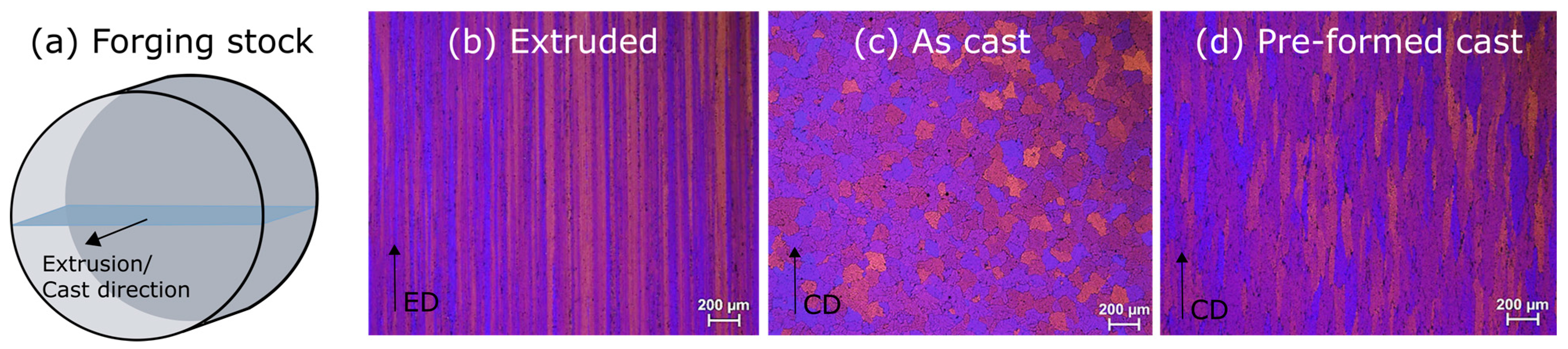
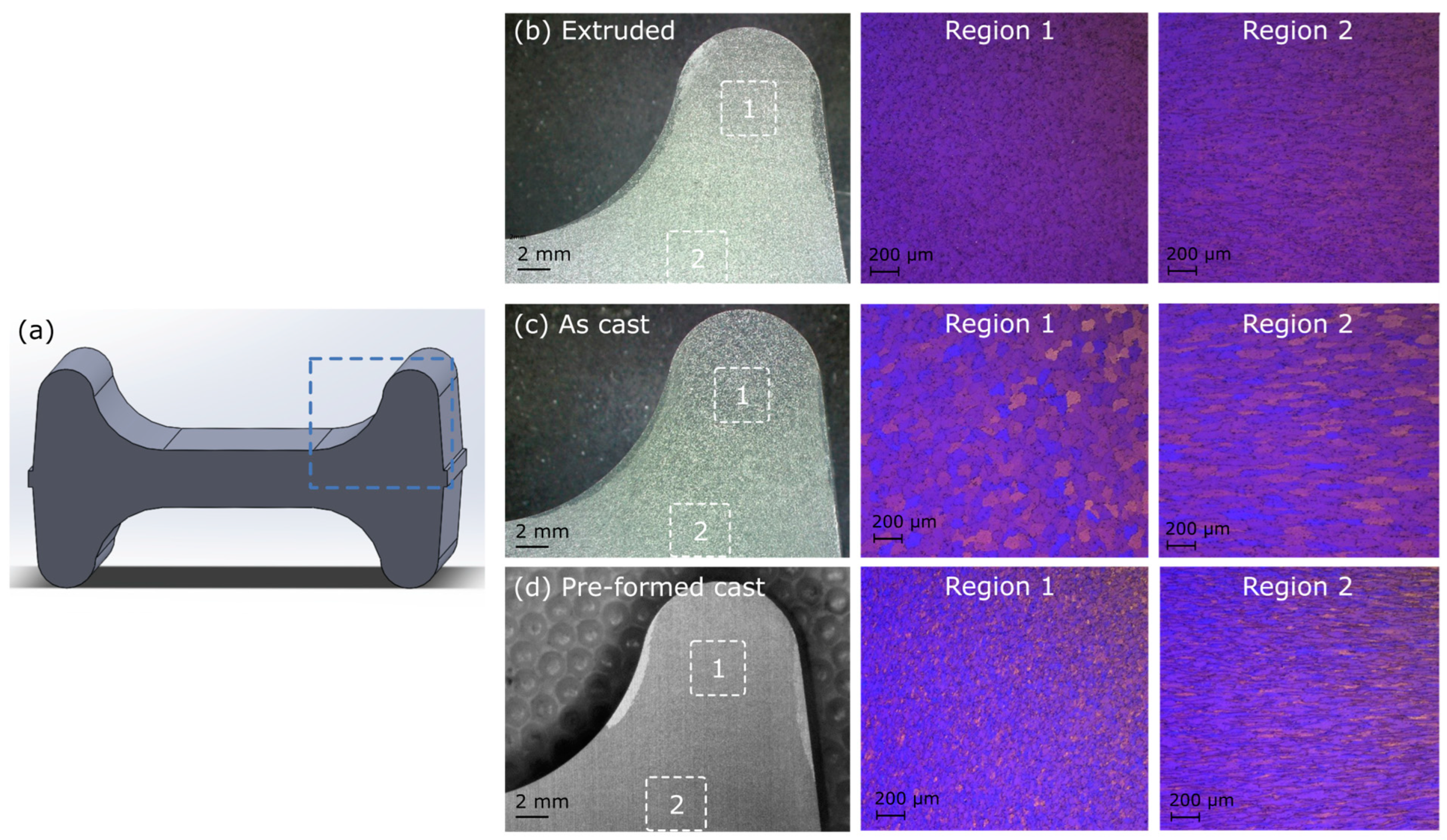
3.1.1. Initial Microstructure of the Forging Stocks

The initial microstructure of the extruded, as-cast and pre-formed cast forging stocks is shown in Figure 5b–d, obtained from the cross-section illustrated in Figure 5a, i.e., the microstructure is viewed parallel to extrusion (ED) and casting direction (CD). Both the extruded and cast forging stock exhibited the expected microstructure, elongated grains with a clear extrusion texture for the extruded and equiaxed grains for the as cast material, with an average grain size of 81 μm. The pre-formed cast microstructure consisted of elongated and slightly deformed grains resulting from the CWR pre-forming process, in which the material was compressed and elongated simultaneously.

3.1.2. Microstructure and Mechanical Properties after Forging

The microstructure was examined after the post-forging T6 heat treatment. The cross-sections of the forged components were viewed, as illustrated in Figure 6a. The macro and microstructure images are shown in Figure 6b–d. In the case of extruded forging stock (Figure 6b), coarse surface grains were observed on both the inside and outside of the component. The thickness of the coarse surface layer averaged between 0.72 and 0.76 mm on the outer edge. For the as cast forging stock (Figure 6c), the coarse surface grain layer was thinner, measuring between 0.28 and 0.34 mm. The pre-formed cast forging stock (Figure 6d) exhibited a surface layer thickness between 0.42 and 0.50 mm.
The cross sections shown in Figure 6 are oriented transversely to the extrusion/casting direction. Consequently, the extruded forging stock exhibited a very fine grain structure, making it difficult to distinguish between each grain. For the cast forging stock, the cast microstructure was observed to be intact in the highlighted region 1, while in region 2 a deformed grained morphology was observed. For the pre-formed cast, the microstructure consisted of fine small grains, smaller than for the cast, but still larger than for the extruded material. Like the microstructure for the cast forging stock, region 2 consisted of deformed grains. Due to the significant deformation and resulting small grain size, the grain size could not be measured with sufficient confidence from the obtained images and utilized characterization technique.
The results from the conducted tensile tests are listed in Table 1, detailing the yield strength (Rp0.2), tensile strength (Rm), elongation at fracture (A), and the percentage reduction of the area at the fracture (Z), from the longitudinal and transverse directions (see Figure 3a). In the longitudinal direction, the extruded material achieved the highest strength, both Rp0.2 and Rm. However, in the transverse direction, the strength difference between the feedstock materials was smaller. The extruded material experienced a reduction in strength of approximately 30 MPa when changing the direction of the tensile specimen, indicating an anisotropy of the mechanical properties. The cast and pre-formed cast materials displayed a slight increase in strength of 10 MPa when changing from the longitudinal to the transverse direction, suggesting more isotropic properties. Nevertheless, the pre-formed cast material had the lowest strength while achieving a higher Z value, surpassing 50% in both directions as compared to the as cast and extruded materials after forging. For the cast material, the Z value was sensitive to the direction of the test specimen, approaching a value close to the pre-formed cast only in the transverse direction.

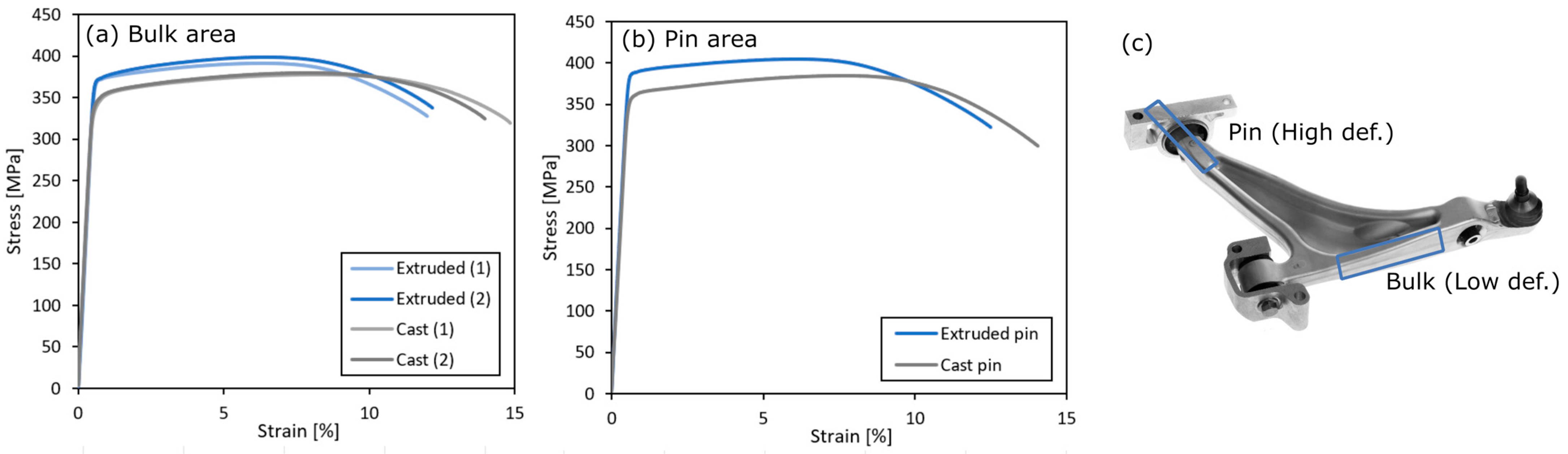
3.2. Full-Scale Production Trials of FLCA

The macro and microstructure of the forged FLCAs from cast and extruded forging stock are compared in Figure 7, showing the two different positions: the bulk and pin area. These two positions represent areas where the material has achieved a different degree of forming, referred to as low in the bulk area and high in the pin area. In position 1, the pin area, coarse surface grains were evident in both the extruded and cast forging stock components. The maximum thickness of the coarse surface grain layer measured 3.3 mm for the extruded stock and only 1.2 mm for the cast stock. In position 2, the bulk, coarse surface grains were observed for the extruded forging stock, while no significant surface grain was observed for the cast forging stock in this region.
A clear difference between the two forging stocks was also found in the microstructure, as highlighted in Figure 7. The grains in the FLCA produced from cast forging stock were coarser compared to the extruded, but with a deformed characteristic. In this specific position, the average grain size was estimated to be between 20 and 30 μm for the extruded FLCA and approximately 35 and 45 μm for the cast FLCA, transverse to the ED and CD.
The results from the mechanical testing of the forged FLCAs are shown in Figure 8a,b in T5 condition and are listed in Table 2. The tensile test specimens were extracted from two positions, shown again in Figure 8c. The T6 mechanical properties were also documented in the standard bulk area for the as cast forging stock.
Overall, the suspension component produced from extruded forging stock achieved higher yield and tensile strength on both positions compared to the suspension component produced from as cast in the T5 condition. The achieved Z value was on the other hand higher for the as cast material in both positions. The Z value for the cast material was also found to increase from around 40% in the low deformation area to above 50% in the pin-area, the area which was known to have achieved the highest accumulated degree of deformation. For the extruded material, no difference was found in the Z value between the two positions. As shown in Table 2, in T6 condition, both a higher yield and tensile strength was achieved in the FLCA produced with cast forging stock compared to the T5 condition. At the same time, the as cast forging stock maintained a high Z value also in the T6 condition, superior to the extruded forging stock.
Fatigue trials using fully assembled FLCAs, i.e., after installation of the integrated ball-joints and bushings, were performed on the components forged with the cast forging stock in T5 condition. The results from these fatigue trials are listed in Table 3 for three of the trials. Overall, the components produced from cast forging stock fulfilled the requirements of lasting 18,040 cycles before failure, given by the automaker for this product. The results also show that the component produced from the cast forging stock performed on par with the average for components produced from extruded forging stock.

4. Discussion

In both the generic forging trial and the LCA, columnar coarse surface grains were observed in the components for the as cast and extruded forging stocks. The cross-sections examined from the two trials show that the cast forging stock exhibited much less growth of this layer compared to the extruded stock. The observed surface grain growth in the extruded material was attributed to the accumulated strain resulting from the extrusion process, providing a driving force for recrystallization during heat treatment. As shown in this study, the cast material displayed a higher surface recrystallization resistance, even after pre-forming and the introduction of a large degree of plastic deformation into the LPC material from the CWR process. In the homogenized cast forging stock, dispersoids had already precipitated in the structure prior to forging. The homogenization temperature and time impact the distribution and density of the dispersoids, directly influencing the hot formability of the alloy [9,26]. When precipitated in the microstructure, the dispersoids were less effective at preventing grain growth when combined with high accumulated strain [9,16]. The higher robustness and resilience against surface grain growth in the forged component produced from cast material has also been demonstrated for other forging processes, thus our results support the existing literature [6,8,19]. The reduction in the columnar coarse surface grain layer was a significant advantage for cast forging stock as it promotes a high surface quality, ensuring a reliable end product [11]. Additionally, the final quality of the forged component will be less susceptible to process instabilities, such as prolonged exposure to high temperatures during forming arising due to factors such as production stops.
In many forging lines, pre-forming techniques such as CWR, compression, bending, or edging are performed to optimize material yield during forging [2]. The microstructural analysis performed in this study revealed a distinct microstructure in the pre-formed cast material, characterized by compressed and elongated grains resulting from the CWR process. These microstructural features resemble those of extruded material. The pre-forming results in a fine-grained structure after forging, with a grain size in between what was observed for cast and extruded stock, based on qualitative analyses. The impact of the pre-forming and the large degree of plastic deformation achieved via CWR prior to forging was evident not only in the microstructure, but also reflected in the mechanical properties. In the generic forging trial, no significant positive influence on strength, Rp0.2 and Rm, was found between the pre-formed cast and cast forging stock. However, a significant increase in the Z value, especially in the longitudinal direction was found. In the forged FLCA from the cast forging stock, a significant increase in strength and Z value was observed between the two investigated areas, the low deformation (bulk) and high deformation (pin) areas (see Table 2). The pin area of the FLCA corresponds to the section of the CWR component used as feedstock material in the generic forging trials, i.e., pre-formed cast forging stock. The presented results show that a high degree of plastic deformation was necessary to obtain a high strength and ductility, represented by the Z value for LPC material. Similar trends have been reported previously in hot-forming trials of the LPC material [27].
In the generic forging trials, the pre-formed material underwent cooling to room temperature after CWR. This was followed by intermediate storage and lastly re-heating before the forging trial. The lack of observed strength increases between the pre-formed and cast forging stock can be attributed to the suboptimal thermomechanical process experienced by the material, differing from the FLCA production line, see Figure 1b. Differences in the obtained strength in the longitudinal direction were also observed in the T6 temper when comparing the generic and the FLCA forging trials for the cast forging stock. These differences highlight the value of conducting trials at both lab and industrial scale, as it contributes to an increased understanding of key factors influencing the obtained properties. For instance, variations in the thermomechanical process and the product design influence the experienced degree of plastic deformation in the tested material, contributing to the observed differences. Industrial-scale trials provide the manufacturer with valuable insight into potential areas for process optimization. For the FLCA, the extruded material achieved a higher strength than the cast in T5 temper. However, the cast forging stock achieved better ductility, represented by the Z value, a crucial feature for the FLCA. Moreover, in T6 condition the cast material achieved properties on par with the extruded material in T5. Thus, the cast material has the potential of achieving a higher strength than what was obtained with the currently established T5 temper processes. Additionally, the full-scale component fatigue trials demonstrate that the FLCA produced from cast forging stock in T5 condition exhibited a high structural integrity and desirable performance, meeting the OEM requirements for the current product. Nevertheless, future work will focus on critically reviewing the thermomechanical process, exploring the effect of adjusting the solution heat treatment temperature, time and/or the aging process.
In 6xxx alloys, there is a strong link between the chemistry of the alloy and the achievable strength level. Therefore, the selection of alloy chemistry should align with the specific requirements of the product. For AA6082 aluminum alloys, the obtainable strength is influenced by factors such as the Mg/Si ratio, the hardening particles β″ (Mg5Si6), and microstructural features including grain size [14,28,29]. In this study, the grain size in the forged FLCA components was measured to support the qualitative observations made from the optical microscopy images (see Figure 7). It confirmed that the extruded material exhibited a finer grain size than the cast material in the evaluated cross-section, transverse to the initial extrusion and casting direction, contributing to a higher strength. However, in complex forged components, assessing the grain size in one cross-section does not provide a sufficient overview of the microstructural morphology and the observed differences in grain size do not solely explain the observed differences in strength between the extruded and cast forging stock. In aluminum alloys, dynamic recovery during hot deformation is known to occur, leading to a dislocation substructure and subgrains with low-angle grain boundaries [30]. Subgrains enhance dislocation density, contributing to increased ductility [31], as observed in the current study for the cast material. The formation of a subgrain structure during the forging of cast AA6061 aluminum alloy was argued to be an important factor in promoting a high strength and especially a high fracture toughness [20,21]. In addition, deformation-induced dislocations also influence the precipitation during aging, strongly influencing the achieved mechanical properties [15]. The presented results emphasize the need for further research on forged components based on cast material. Such extended investigation should include advanced characterization such as scanning (SEM) and transmission electron microscopy (TEM) to explore the subgrain structure and the strengthening particles present in the structure, to enhance the understanding. Simulations of the forging processes would also be of high value to assess the accumulated plastic deformation in different sections of the forged component and relate this to observed differences in strength and microstructure. The value of such work has been shown for other forged automotive components [2,3,32].

5. Conclusions

The current study highlights the potential for replacing extruded stock with LPC forging stock in the production of forged aluminum components. Evaluation of the microstructure and mechanical properties achieved through an industrial proof-of-principle study involved two different forging trials. Key findings include:
  • The microstructural investigations revealed a reduced surface grain growth in the forged components produced from cast material, enhancing product reliability and robustness against pauses in a production line.
  • The mechanical properties of the cast material were found to increase with the increasing degree of plastic deformation, making the LPC material well suited for the forging of complex components where the production process includes pre-forming. The variation between obtained strength in T6 temper in the generic and the full-scale industrial production trials emphasizes the influence of product design, i.e., differences in introduced deformation on the final properties.
  • Directly replacing extruded forging stock with cast in the FLCA production yields comparable mechanical properties: a slightly lower strength, but with higher ductility in T5 temper. In T6 temper the properties of the cast FLCA were in line with the extruded material. Optimizing the thermomechanical process further is required to achieve the desired properties in T5 temper.
  • The high ductility combined with the desirable microstructure promoted a high structural integrity and ensured a high structural integrity, as evident from FLCA fatigue trails.
In conclusion, the study provides a foundation for further exploration into alloy and process parameter optimization for cast forging stock. Additional research focusing on further microstructural analysis combined with simulations of the forging process would contribute valuable insight that can advance the application of LPC in the automotive industry.

Author Contributions

Conceptualization, S.M.A., S.T., M.H.B., U.T., J.L., S.D. and O.J.; methodology, S.M.A., M.H.B., U.T., J.L., S.D. and O.J.; investigation, S.M.A. and O.J.; resources, S.T., M.H.B., U.T. and J.L.; writing—original draft preparation, S.M.A. and O.J.; writing—review and editing, S.M.A., S.T., M.H.B., U.T., S.D. and O.J.; visualization, S.M.A., M.H.B., J.L., S.D. and O.J.; supervision, S.T. and M.H.B.; project administration, S.M.A., S.T., M.H.B. and J.L.; funding acquisition, S.T. All authors have read and agreed to the published version of the manuscript.

Funding

This research was funded by The Research Council of Norway (NRC), contract number 295873.

Data Availability Statement

The data presented in this study are available in article.

Acknowledgments

The research was conducted as part of the NRC-funded BIA-IPN project HyForge (HyForge™—Low Pressure Casting material: a game changer towards high quality and cost- effective forging). The project is owned by Hydro Aluminium AS with the following project partners: Raufoss Technology AS, SINTEF Manufacturing and SINTEF Industry. The authors acknowledge the contribution to this work by the staff at Raufoss Technology AS for the production of the investigated forged front lower control arms.

Conflicts of Interest

Authors Siri Marthe Arbo and Ola Jensrud were employed by the company SINTEF Manufacturing. Authors Stig Tjøtta, Magne H. Boge and Ulf Tundal were employed by the company Hydro Aluminium Primary Metal. Author Jørgen Li was employed by the company Raufoss Technology. Author Stephane Dumoulin was employed by the company SINTEF Industry. SINTEF Manufacturing and SINTEF Industry were research partners in the project and had the role as the principal investigators. All authors declare that the research was conducted in the absence of any commercial or financial relationships that could be construed as a potential conflict of interest. The funders had no role in the design of the study; in the collection, analyses, or interpretation of data; in writing of the manuscript; or in the decision to publish the results.

References

  1. Ducker Worldwide. Aluminium Content in European Passenger Cars. Public Summary. European Aluminium Association. 2019. Available online: https://european-aluminium.eu/wp-content/uploads/2022/10/aluminum-content-in-european-cars_european-aluminium_public-summary_101019-1.pdf (accessed on 13 November 2023).
  2. Fuh, Y.K.; Shih, J.K.; Saputro, I.E.; Chen, C.P.; Huang, C.F.; Ku, H.Y.; Chan, C. Preform design with increased materials utilization and processing map analysis for aluminum hot forging process. J. Manuf. Process 2023, 90, 14–27. [Google Scholar] [CrossRef]
  3. Chen, X.; Shu, X.; Wang, D.; Xu, S.; Xiang, W. Multi-Step Forming Simulation and Quality Control of Aluminum Alloy Automobile Rear Upper Control Arm. Materials 2022, 15, 3610. [Google Scholar] [CrossRef]
  4. Kuhlman, G.W. Forging of Aluminum Alloys. In ASM Handbook Volume 14A: Metalworking: Bulk Forming; ASM International: New York, NY, USA, 2005; pp. 299–312. [Google Scholar] [CrossRef]
  5. Tunc, O.; Kacar, I.; Ozturk, F. Investigation of forging performance for AA6082. Int. J. Adv. Manuf. Technol. 2021, 117, 1645–1661. [Google Scholar] [CrossRef]
  6. Płonka, B.; Kłyszewski, A.; Senderski, J.; Lech-Grega, M. Application of Al alloys, in the form of cast billet, as stock material for the die forging in automotive industry. Arch. Civ. Mech. Eng. 2008, 8, 149–156. [Google Scholar] [CrossRef]
  7. Birol, Y.; Gokcil, E.; Guvenc, M.A.; Akdi, S. Processing of high strength EN AW 6082 forgings without a solution heat treatment. Mater. Sci. Eng. A 2016, 674, 25–32. [Google Scholar] [CrossRef]
  8. Birol, Y.; Ilgaz, O. Effect of cast and extruded stock on grain structure of EN AW 6082 alloy forgings. Mater. Sci. Technol. 2014, 30, 860–866. [Google Scholar] [CrossRef]
  9. Sandvik, J.; Jensrud, O.; Gulbrandsen-Dahl, S.; Hallem, H.; Moe, J.I. Through Process Prevention of Recrystallization in Hot Formed Aluminium Structural Car Components. Mater. Sci. Forum 2010, 638–642, 315–320. [Google Scholar] [CrossRef]
  10. Zhao, N.; Ma, H.; Sun, Q.; Hu, Z.; Yan, Y.; Chen, T.; Hua, L. Microstructural evolutions and mechanical properties of 6082 aluminum alloy part produced by a solution-forging integrated process. J. Mater. Process Technol. 2022, 308, 117715. [Google Scholar] [CrossRef]
  11. Očenášek, V.; Sedláček, P. The effect of surface recrystallized layers on properties of extrusions and forgings from high strength aluminium alloys. In Conference Proceedings—Metal 2011; Tanger, Ltd.: Brno, Czech Republic, 2011. [Google Scholar]
  12. Pedersen, K.; Jensrud, O.; Moe, J.I.; Roven, H.J. Fatigue, fracture and microstructure relationships of an aluminium automobile component. In ECF 8 Fracture Behaviour and Design of Materials and Structures; Gruppo Italiano Frattura: Turin, Italy, 1990. [Google Scholar]
  13. Gokcil, E.; Akdi, S.; Birol, Y. A novel processing route for the manufacture of EN AW 6082 forged components. Mater. Res. Innov. 2015, 19, S10-311–S10-314. [Google Scholar] [CrossRef]
  14. Hua, L.; Yuan, P.; Zhao, N.; Hu, Z.; Ma, H. Microstructure and mechanical properties of 6082 aluminum alloy processed by preaging and hot forging. Trans. Nonferrous Met. Soc. 2022, 32, 790–800. [Google Scholar] [CrossRef]
  15. Hu, Z.; Zheng, J.; Pang, Q.; Sun, Q.; Zhao, N. Influence of strain rates and aging time on microstructure and hardness of integrally compressed 6082 aluminum alloy. J. Mater. Res. Technol. 2023, 27, 826–838. [Google Scholar] [CrossRef]
  16. Tundal, U.; Tveito, K.O.; Berg, S.S.; Moen, L.; Boge, M. Low-Pressure Casting Technology Represents Step Change in Producing High Quality Forging Stock. Light Met. Age 2020, 12, 24–29. [Google Scholar]
  17. Bobba, S.; Roa, M.S.; Raj, P. Experimental Analysis on the Forging Process of Al 6061 and Al 7075 Aluminium Alloys. SunText Rev. Mater. Sci. 2021, 2, 111. [Google Scholar] [CrossRef]
  18. Birol, Y.; Ilgaz, O.; Akdi, S.; Unuvar, E. Comparison of Cast and Extruded Stock for the Forging of AA6082 Alloy Suspension Parts. Adv. Mater. Res. 2014, 939, 299–304. [Google Scholar] [CrossRef]
  19. Chang, Y.L.; Hung, F.Y.; Lui, T.S. Study of microstructure and tensile properties of infrared-heat-treated cast-forged 6082 aluminum alloy. J. Mater. Res. Technol. 2019, 8, 173–179. [Google Scholar] [CrossRef]
  20. Hosoda, N.; Nakai, M.; Eto, T. The Effect of Microstructure on Mechanical Properties of Forged 6061 Aluminum Alloy. In Proceedings of the 9th International Conference on Aluminium Alloys (2004), Brisbane, Australia, 2–5 August 2004. [Google Scholar]
  21. Nakai, M.; Itoh, G. The Effect of Microstructure on Mechanical Properties of Forged 6061 Aluminum Alloy. Mater. Trans. 2014, 55, 114–119. [Google Scholar] [CrossRef]
  22. Hydro. HyForgeTM—High-Quality Forging Material from Hydro. 2023. Available online: https://www.hydro.com/en/aluminium/products/casthouse-products/hyforge/ (accessed on 1 October 2023).
  23. Nunes, H.; Emadinia, O.; Vieira, M.F.; Reis, A. Low- and High-Pressure Casting Aluminum Alloys: A Review. In Recent Advancements in Aluminum Alloys; IntechOpen: London, UK, 2023; Available online: https://www.intechopen.com/online-first/85913 (accessed on 30 December 2023).
  24. Håkonsen, A.; Ledal, R.; Hafsås, E.; Røyset, J. Game Changer for Extrusion Billet Surface Quality. In Proceedings of the Eleventh International Aluminium Extrusion Technology Seminar (ET’16), Chicago, IL, USA, 2–6 May 2016. [Google Scholar]
  25. NS-EN ISO 6892-1:2019; Metallic Materials—Tensile Testing—Part 1: Method of Test at Room Temperature, International Organization for Standardization. ISO: Geneva Switzerland, 2019.
  26. Arnoldt, A.R.; Schiffl, A.; Höppel, H.W.; Österreicher, J.A. Influence of different homogenization heat treatments on the microstructure and hot flow stress of the aluminum alloy AA6082. Mater. Charact. 2022, 9, 112129. [Google Scholar] [CrossRef]
  27. Tundal, U.; Tjøtta, S.; Li, J.; Dumoulin, S.; Arbo, S.M.; Jensrud, O. The potential for Cast Aluminum Forge Stock to Produce High-Performance Automotive Suspension Components. Light Met. Age 2022, 12, 24–28. [Google Scholar]
  28. Gupta, A.K.; Lloyd, D.J.; Court, S.A. Precipitation hardening in Al–Mg–Si alloys with and without excess Si. Mater. Sci. Eng. A 2001, 316, 11–17. [Google Scholar] [CrossRef]
  29. Marioara, C.D.; Andersen, S.J.; Jansen, J.; Zandbergen, H.W. The influence of temperature and storage time at RT on nucleation of the β″ phase in a 6082 Al–Mg–Si alloy. Acta Mater. 2003, 51, 789–796. [Google Scholar] [CrossRef]
  30. Humphreys, F.J.; Hatherly, M. Recrystallization and Related Annealing Phenomena, 2nd ed.; Elsevier: Amsterdam, The Netherlands, 2004. [Google Scholar] [CrossRef]
  31. Wang, Y.; Zhao, Y.; Xu, X.; Pan, D.; Jiang, W.; Chong, X. Simultaneously Enhanced Strength and Ductility of Al–Mg–Si Alloys during Aging Process Induced by Electro-Pulsing Treatment. Materials 2019, 12, 1383. [Google Scholar] [CrossRef] [PubMed]
  32. Lv, J.; Zheng, J.H.; Yardley, V.A.; Shi, Z.; Lin, J. A Review of Microstructural Evolution and Modelling of Aluminium Alloys under Hot Forming Conditions. Metals 2020, 10, 1516. [Google Scholar] [CrossRef]
Figure 1. (a) Image of the fully assembled front lower control arm produced in this study. (b) Thermomechanical process for the production of the front lower control arm at Raufoss Technology.
Metals 14 00090 g001
Figure 2. Illustration of the steps during the generic forging trials.
Metals 14 00090 g002
Figure 3. (a) Illustration of the forged component and position of the tensile specimens in transverse and longitudinal direction, (b) dimensions of the extracted tensile specimens.
Metals 14 00090 g003
Figure 4. (a) Position of the tensile test specimens of the forged front lower control arm. (b) Setup for the in-house fatigue trials of fully assembled front lower control arms.
Metals 14 00090 g004
Figure 5. (a) Illustration of investigated cross-section in forging stock. Initial microstructure of the (b) extruded, (c) as cast and (d) pre-formed cast forging stock. ED: extrusion direction. CD: casting direction.
Metals 14 00090 g005
Figure 6. Macro and microstructure in highlighted region in (a) of the forged components for (b) extruded, (c) as cast and (d) pre-formed forging stock.
Metals 14 00090 g006
Figure 7. Macro and microstructure in selected positions in the forged front lower control arms. (Top): extruded forging stock. (Bottom): cast forging stock. The front lower control arm and the investigated positions are highlighted on the suspension component on the left.
Metals 14 00090 g007
Figure 8. (a) Bulk area with low deformation; (b) pin area with high deformation; (c) image of the front lower control arm and position of the extracted tensile test specimens.
Metals 14 00090 g008
Table 1. Mechanical properties achieved in components forged with generic forging tool after T6 heat treatment. Results show the average ± deviation between the performed parallels.
IdentificationPosition/DirectionRp0.2RmAZ 1
MPaMPa%%
Extruded–T6Longitudinal391.5 ± 0.5406.5 ± 0.510.0 ± 0.342.0 ± 0.0
Cast–T6Longitudinal356.5 ± 0.5376.5 ± 0.59.7 ± 0.128.0 ± 5.0
Pre-formed cast–T6Longitudinal344.8 ± 1.0362.5 ± 0.111.5 ± 0.651.5 ± 1.5
Extruded–T6Transverse363.3 ± 2.6382.0 ± 2.98.9 ± 0.145.0 ± 0.8
Cast–T6Transverse370.3 ± 0.9393.3 ± 1.212.2 ± 0.848.7 ± 0.9
Pre-formed cast–T6Transverse357.5 ± 2.2377.7 ± 2.012.2 ± 0.350.0 ± 2.9
1 Z: percentage of reduction of area at fracture [25] was measured manually after fracture.
Table 2. Mechanical properties achieved in the forged FLCA, for extruded and cast forging stock in T5 condition in standard bulk and pin area, and in T6 condition for the cast forging stock as a reference in the standard bulk area. Results show the average ± deviation between the performed parallels.
IdentificationPositionRp0.2RmAZ 1
MPaMPa%%
Extruded–T5, Reference from current productionBulk area (standard)376.3 ± 4.0399.2 ± 5.512.1 ± 0.936.8 ± 1.2
Pin area 3884051238
Cast–T5Bulk area (standard)345.5 ± 2.5378.1 ± 113.7 ± 0.842.4 ± 3.0
Pin area 369.8 ± 6.5 381.3 ± 6.8 14.1 ± 0.750.3 ± 2.9
Cast–T6Bulk area (standard) 376.0 ± 2.0403.5 ± 1.513.1 ± 1.245.0 ± 2.0
1 Z: percentage of reduction of area at fracture [25] was measured manually after fracture.
Table 3. Results from the full-scale fatigue testing of the fully assembled front lower control arms with integrated ball-joint.
IdentificationNumber of Cycles before Failure
Requirement18,040
Extruded T5–reference average from current production141,466
Cast T5–component (1)162,360
Cast T5–component (2)135,745
Cast T5–component (3)139,794
Disclaimer/Publisher’s Note: The statements, opinions and data contained in all publications are solely those of the individual author(s) and contributor(s) and not of MDPI and/or the editor(s). MDPI and/or the editor(s) disclaim responsibility for any injury to people or property resulting from any ideas, methods, instructions or products referred to in the content.

