
Electrochemical Investigation of Chloride Ion-Induced Breakdown of Passive Film on P110 Casing Steel Surface in Simulated Pore Solution: Behavior and Critical Value Determination

Abstract
:1. Introduction
2. Experimental
2.1. Materials and Environment
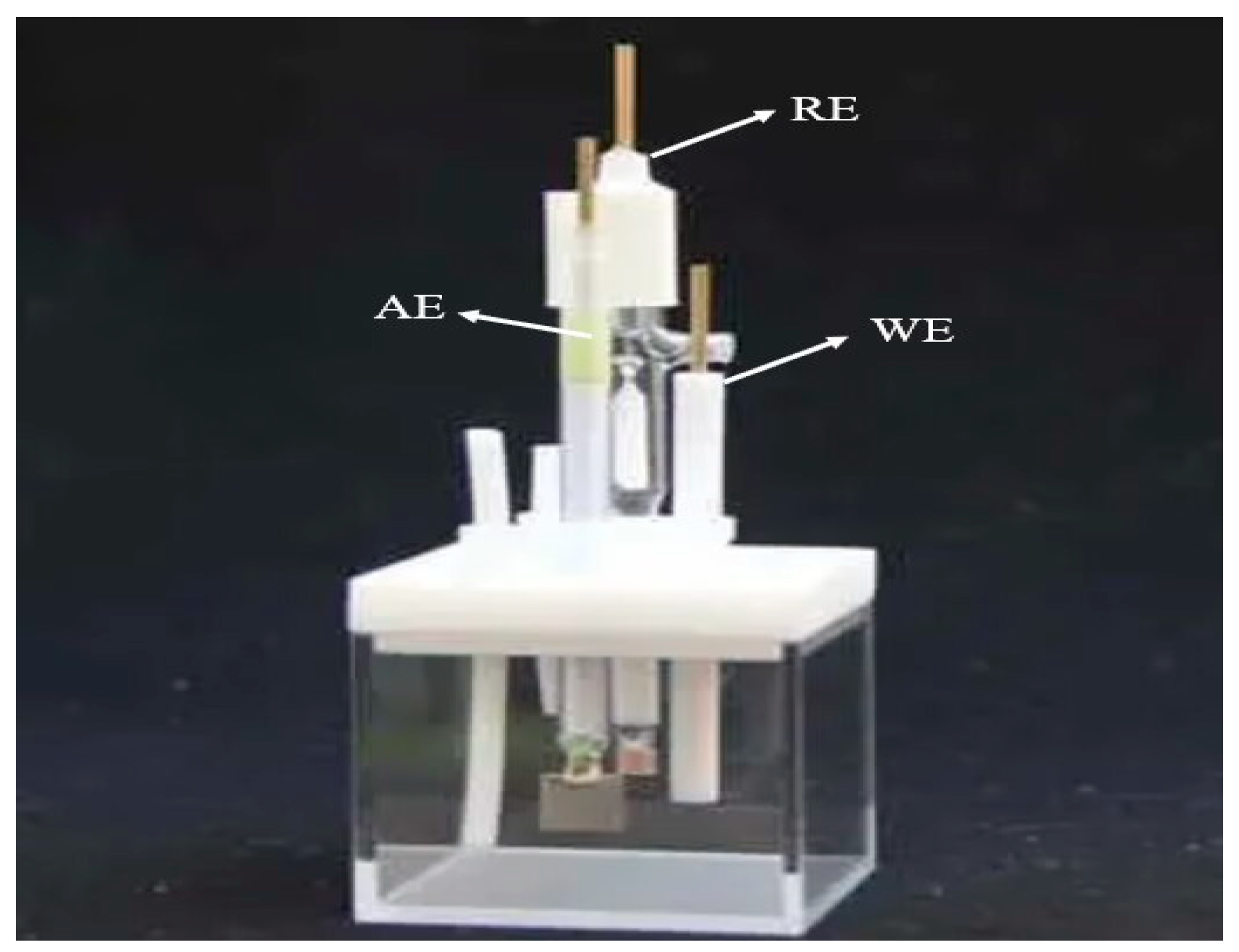
2.2. Electrochemical Measurements
2.3. Material Characterization
3. Results and Discussion
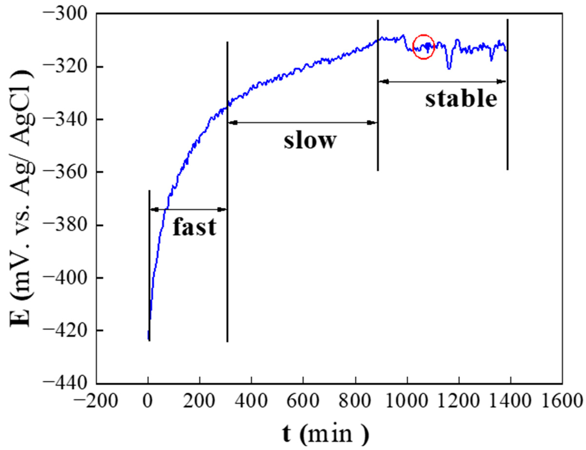
3.1. Determination of Steady-State Passivation Time
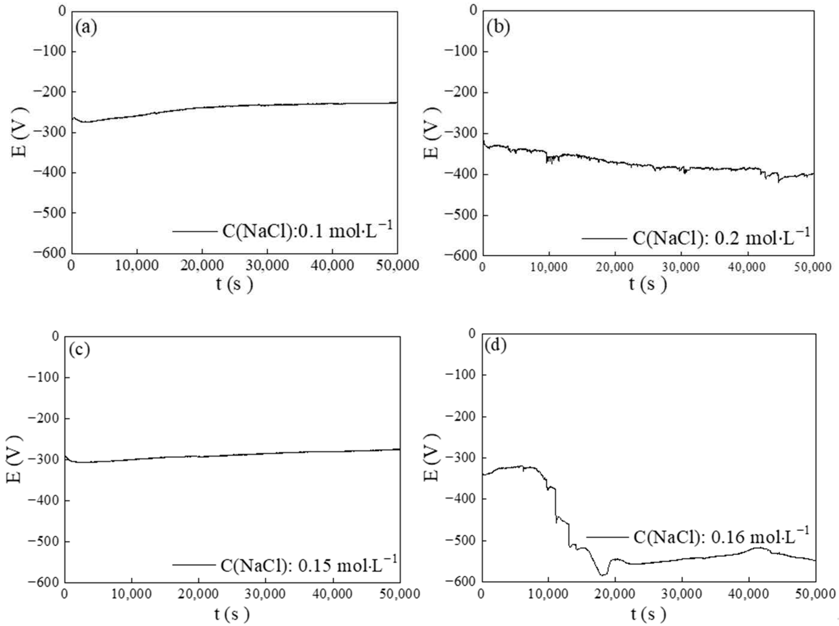
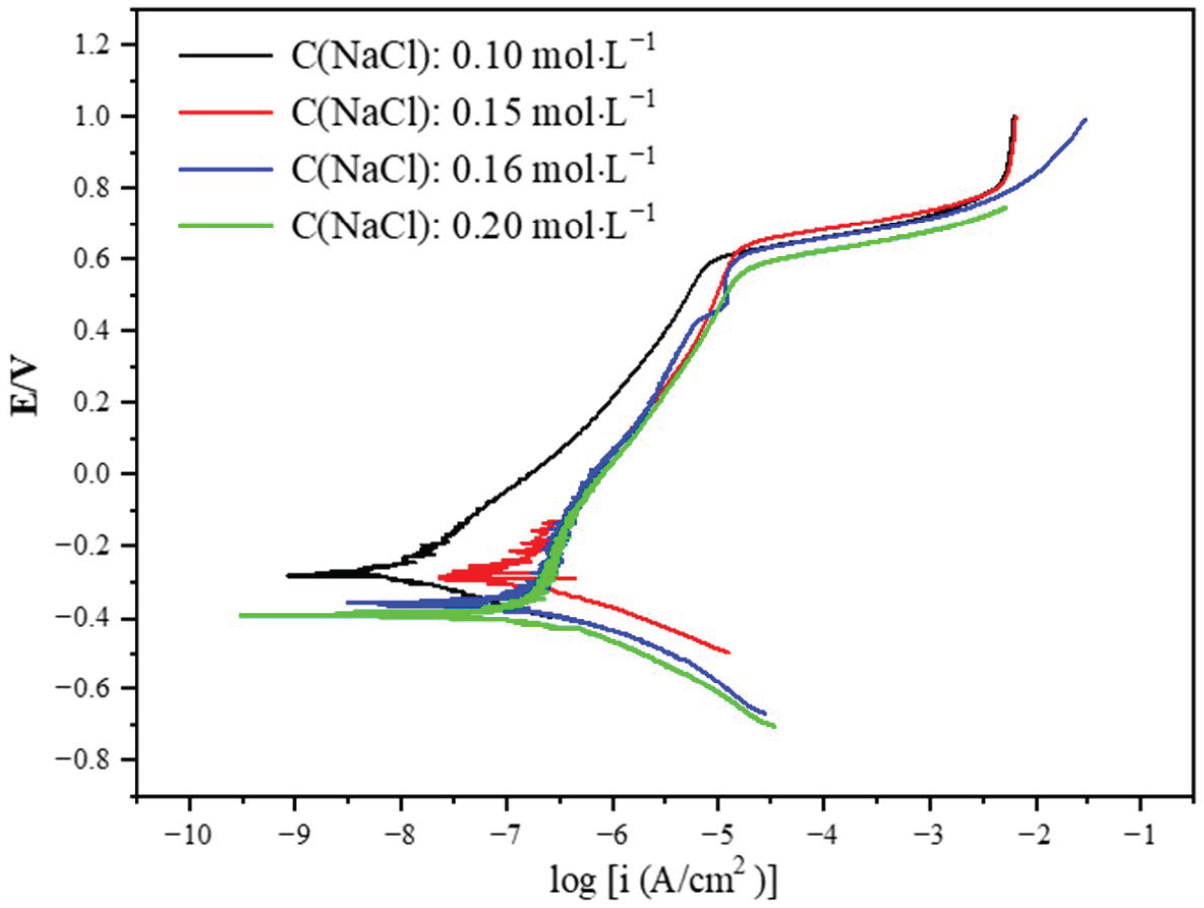
3.2. Electrochemical Behavior of Chloride Ions in Depassivation
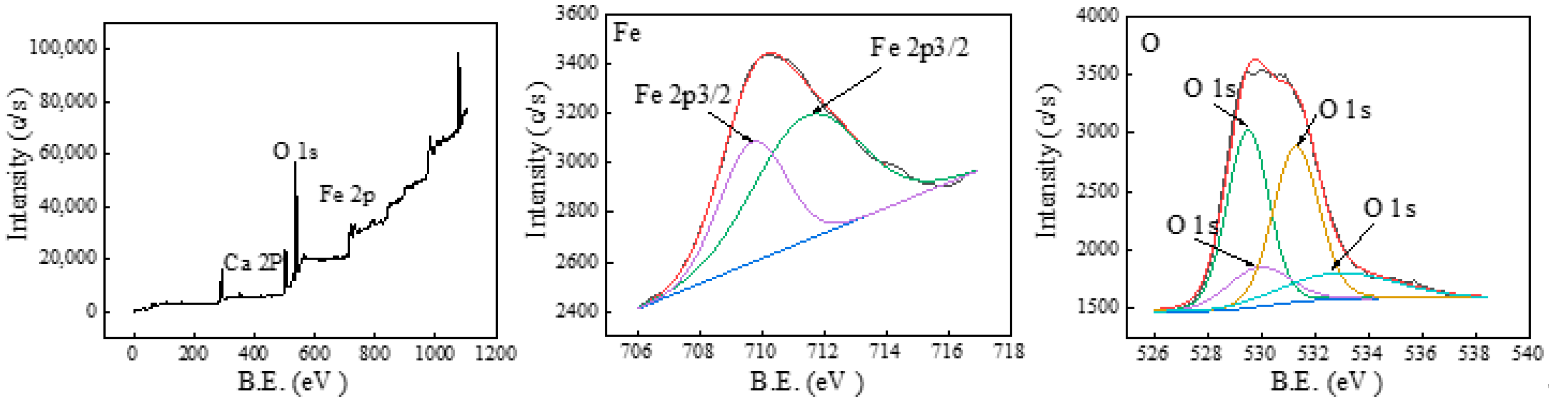
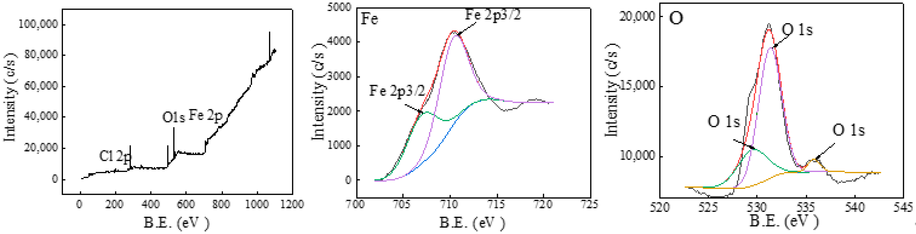
3.3. Analysis of the Film Components
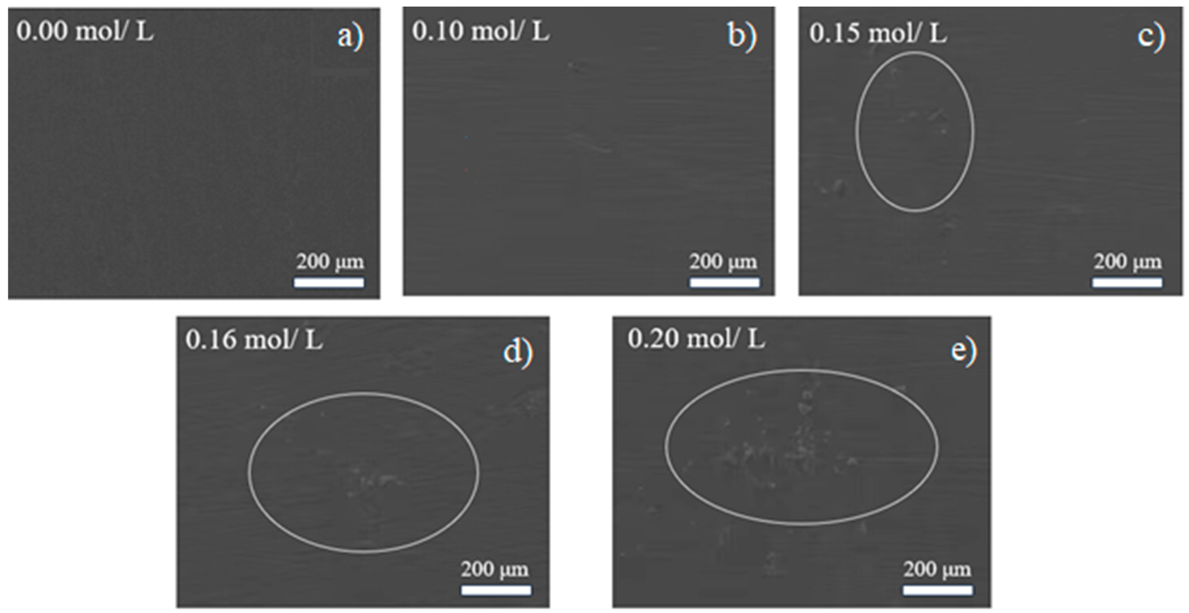
3.4. Surface Morphology of Passive Film
4. Conclusions
- Here, we propose a method to determine the critical concentration of chloride ions for the destruction of the passive film. The critical chloride ion concentration can be determined using a potential–time curve, anode polarization curve, and electrochemical impedance spectroscopy testing.
- The critical concentration of chloride ions for the destruction of the passive film in a simulated pore solution was determined to be 0.16 mol/L at a temperature of 65 °C and a pH value of 12.5.
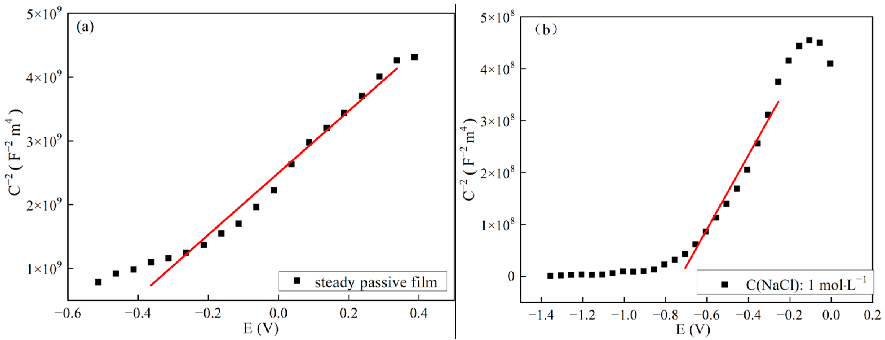
- The passive film subjected to chloride ion damage was the n-type semiconductor, just like the steady-state passive film in equilibrium. The passive film contained more oxygen vacancies and metal ion vacancies. In the passive film, an increase in the concentration of donors or acceptors made the film more susceptible to damage.
- The components of the passive film eroded by chloride ions were M-O-Cl, Fe2O3, and Fe(OH)2. Compared with the steady-state passive film, the characteristic product was M-O-Cl.
- Under the five chloride ion concentrations used in the experiment, only 0.16 mol/L and 0.20 mol/L chloride ion conditions resulted in pitting corrosion on the surface of P110 casing steel, which could correspond to the conclusions obtained from electrochemical experiments.
Author Contributions
Funding
Data Availability Statement
Acknowledgments
Conflicts of Interest
References
- Feng, H.; Dai, J.; Li, H.-B.; Jiang, Z.-H.; Qu, J.-D.; Zhao, Y.; Zhang, S.-C.; Zhang, T. Sn microalloying enhances corrosion resistance of stainless steel by accelerating heterogeneous nucleation of passive film. Corros. Sci. 2022, 201, 110279. [Google Scholar] [CrossRef]
- Yuan, X.; Wang, X.; Cao, Y.; Yang, H. Natural passivation behavior and its influence on chloride-induced corrosion resistance of stainless steel in simulated concrete pore solution. J. Mater. Res. Technol. 2020, 9, 12378–12390. [Google Scholar] [CrossRef]
- Jin, Z.; Xiong, C.; Zhao, T.; Du, Y.; Zhang, X.; Li, N.; Yu, Y.; Wang, P. Passivation and depassivated properties of Cr–Mo alloyed corrosion-resistant steel in simulated concrete pore solution. Cem. Concr. Compos. 2022, 126, 104375. [Google Scholar] [CrossRef]
- Karimi, M.S.; Yeganeh, M.; Zaree, S.A.; Eskandari, M. Corrosion behavior of 316L stainless steel manufactured by laser powder bed fusion (L-PBF) in an alkaline solution. Opt. Laser Technol. 2021, 138, 106918. [Google Scholar] [CrossRef]
- Long, H.; Chen, L.; Dong, B.; Sun, Y.; Yan, Y.; Chen, C. The electronic properties and surface chemistry of passive film on reinforcement: Effect of composition of simulated concrete pore solution. Constr. Build. Mater. 2022, 360, 129567. [Google Scholar] [CrossRef]
- Xu, L.; Wu, P.; Zhu, X.; Zhao, G.; Ren, X.; Wei, Q.; Xie, L. Structural characteristics and chloride intrusion mechanism of passive film. Corros. Sci. 2022, 207, 110563. [Google Scholar] [CrossRef]
- Ye, C.; Hu, R.; Dong, S.; Zhang, X.; Hou, R.; Du, R.; Lin, C.; Pan, J. EIS analysis on chloride-induced corrosion behavior of reinforcement steel in simulated carbonated concrete pore solutions. J. Electroanal. Chem. 2013, 688, 275–281. [Google Scholar] [CrossRef]
- Nahali, H.; Dhouibi, L.; Idrissi, H. Effect of phosphate based inhibitor on the threshold chloride to initiate steel corrosion in saturated hydroxide solution. Constr. Build. Mater. 2014, 50, 87–94. [Google Scholar] [CrossRef]
- Tran, D.T.; Lee, H.-S.; Singh, J.K. Chloride threshold determination of hybrid inhibitor immersed in simulated concrete pore solution. Constr. Build. Mater. 2023, 384, 131446. [Google Scholar] [CrossRef]
- Vu, T.H.; Dang, L.C.; Kang, G.; Sirivivatnanon, V. Chloride induced corrosion of steel reinforcement in alkali activated slag concretes: A critical review. Case Stud. Constr. Mater. 2022, 16, e01112. [Google Scholar] [CrossRef]
- Mangat, P.; Ojedokun, O.O.; Lambert, P. Chloride-initiated corrosion in alkali activated reinforced concrete. Cem. Concr. Compos. 2021, 115, 103823. [Google Scholar] [CrossRef]
- Hay, R.; Ostertag, C.P. Acidification at rebar-concrete interface induced by accelerated corrosion test in aggressive chloride environment. Cem. Concr. Compos. 2020, 110, 103573. [Google Scholar] [CrossRef]
- Wang, X.-P.; Shao, M.; Ye, C.-Q.; Dong, S.-G.; Du, R.-G.; Lin, C.-J. Study on effect of chloride ions on corrosion behavior of reinforcing steel in simulated polluted concrete pore solutions by scanning micro-reference electrode technique. J. Electroanal. Chem. 2021, 895, 115454. [Google Scholar] [CrossRef]
- Khaled, M.M.; Yilbas, B.S. Corrosion properties of HVOF-coated steel in simulated concrete pore electrolyte and concentrated chloride environments. Surf. Coat. Technol. 2007, 202, 433–438. [Google Scholar] [CrossRef]
- Ghods, P.; Isgor, O.B.; Bensebaa, F.; Kingston, D. Angle-resolved XPS study of carbon steel passivity and chloride-induced depassivation in simulated concrete pore solution. Corros. Sci. 2012, 58, 159–167. [Google Scholar] [CrossRef]
- Hussain, R.R.; Alhozaimy, A.M.; Al-Negheimish, A. Role of scoria natural pozzolan in the passive film development for steel rebars in chloride-contaminated concrete environment. Constr. Build. Mater. 2022, 357, 129335. [Google Scholar] [CrossRef]
- Peng, Y.; Liu, L.; Wang, S.; Lin, Y.; Sun, Y.; Xia, R. Effect of simulated pore solution on passivation characteristic of P110 steel. J. Pet. Sci. Eng. 2018, 167, 949–956. [Google Scholar] [CrossRef]
- Choi, D.; Was, G.S. Development of a Pit Growth Resistance Parameter for the Study of Pit Growth in Alloy 600. Natl. Assoc. Corros. Eng. 1992, 48, 292–305. [Google Scholar] [CrossRef]
- Tang, Y.; Miao, Y.; Zuo, Y.; Zhang, G.; Wang, C. Corrosion behavior of steel in simulated concrete pore solutions treated with calcium silicate hydrates. Constr. Build. Mater. 2012, 30, 252–256. [Google Scholar] [CrossRef]
- Zhu, Y.; Macdonald, D.D.; Yang, J.; Qiu, J.; Engelhardt, G.R. Corrosion of rebar in concrete. Part II: Literature survey and statistical analysis of existing data on chloride threshold. Corros. Sci. 2021, 185, 109439. [Google Scholar] [CrossRef]
- Saremi, M.; Mahallati, E. A study on chloride-induced depassivation of mild steel in simulated concrete pore solution. Cem. Concr. Res. 2002, 32, 1915–1921. [Google Scholar] [CrossRef]
- Toor, I. Applications of Photoelectrochemical Spectroscopy (PES) and Mott-Schottky Techniques in Corrosion Research. In Recent Developments in Analytical Techniques for Corrosion Research; Springer: Berlin/Heidelberg, Germany, 2022; pp. 11–21. [Google Scholar] [CrossRef]
- Jiang, R.; Wang, Y.; Wen, X.; Chen, C.; Zhao, J. Effect of time on the characteristics of passive film formed on stainless steel. Appl. Surf. Sci. 2017, 412, 214–222. [Google Scholar] [CrossRef]
- Wu, H.; Wang, Y.; Zhong, Q.; Sheng, M.; Du, H.; Li, Z. The semi-conductor property and corrosion resistance of passive film on electroplated Ni and Cu–Ni alloys. J. Electroanal. Chem. 2011, 663, 59–66. [Google Scholar] [CrossRef]
- Büchler, M.; Schmuki, P.; Böhni, H. A light reflectance technique for thickness measurements of passive films. Electrochim. Acta 1998, 43, 635–637. [Google Scholar] [CrossRef]
- Veleva, L.; Alpuche-Aviles, M.A.; Graves-Brook, M.K.; Wipf, D.O. Comparative cyclic voltammetry and surface analysis of passive films grown on stainless steel 316 in concrete pore model solutions. J. Electroanal. Chem. 2002, 537, 85–93. [Google Scholar] [CrossRef]
- Nascimento, C.B.; Donatus, U.; Ríos, C.T.; Antunes, R.A. Electronic properties of the passive films formed on CoCrFeNi and CoCrFeNiAl high entropy alloys in sodium chloride solution. J. Mater. Res. Technol. 2020, 9, 13879–13892. [Google Scholar] [CrossRef]
- Yue, Y.; Liu, C.; Jiang, M. Evolution of Passive Film on 304 Stainless Steel During Nitric Acid Passivation. Steel Res. Int. 2022, 93, 2200026. [Google Scholar] [CrossRef]
- Zhou, S.; Yan, Q.; Tang, C.; Mao, F.; Pu, J.; Macdonald, D.D. Effect of the chloride on passivity breakdown of Al-Zn-Mg alloy. Corros. Sci. 2020, 163, 108254. [Google Scholar] [CrossRef]
- Gluth, G. Chemical resistance of hybrid cements against aggressive saline solutions. In Proceedings of the Joint 6th International Workshop on Mechanisms and Modelling of Waste/Cement Interactions & EURAD—WP CORI Workshop, Prague, Czech Republic, 20–24 November 2023. [Google Scholar]
- Wang, Y.; Xiao, W.; Ma, K.; Dai, C.; Wang, D.; Wang, J. Revealing anti-corrosion behavior of Mg alloy concrete formwork coated with release agents in Cl−-containing Portland cement paste. Constr. Build. Mater. 2023, 406, 133413. [Google Scholar] [CrossRef]
- Ghanbari, E.; Saatchi, A.; Lei, X.; Macdonald, D.D. Studies on Pitting Corrosion of Al-Cu-Li Alloys Part II: Breakdown Potential and Pit Initiation. Materials 2019, 12, 1786. [Google Scholar] [CrossRef]
- Xu, P.; Jiang, L.; Guo, M.Z.; Zha, J.; Chen, L.; Chen, C.; Xu, N. Influence of sulfate salt type on passive film of steel in simulated concrete pore solution. Constr. Build. Mater. 2019, 223, 352–359. [Google Scholar] [CrossRef]
- Cui, Y.-W.; Chen, L.-Y.; Chu, Y.-H.; Zhang, L.; Li, R.; Lu, S.; Wang, L.; Zhang, L.-C. Metastable pitting corrosion behavior and characteristics of passive film of laser powder bed fusion produced Ti–6Al–4V in NaCl solutions with different concentrations. Corros. Sci. 2023, 215, 111017. [Google Scholar] [CrossRef]


| C | Si | Mn | P | S | Cr | Mo | Ni | V | Ti | Cu | Fe |
|---|---|---|---|---|---|---|---|---|---|---|---|
| 0.25 | 0.20 | 1.40 | <0.009 | <0.003 | 0.15 | 0.01 | 0.012 | 0.012 | 0.030 | <0.01 | Bal. |
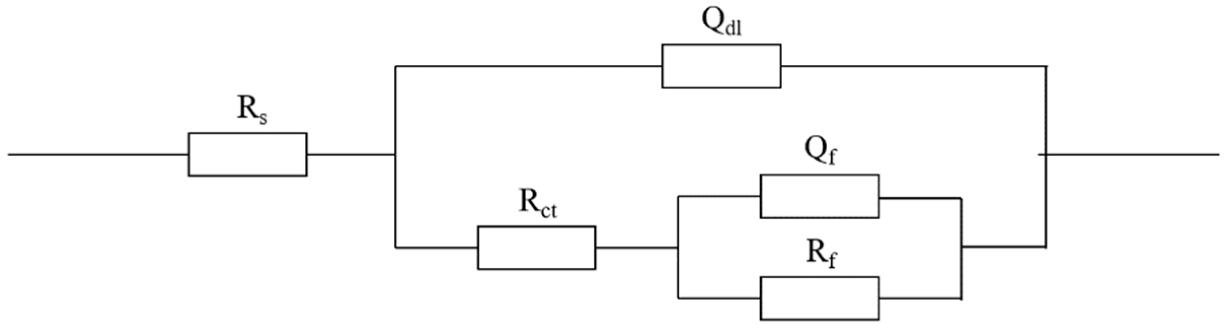
| Concentration (mol·L−1) | Rs (Ω) | Rct (Ω) | Rf (Ω) | χ |
|---|---|---|---|---|
| 0.00 | 8.860 ± 0.08 | 7.334 × 10³ ± 0.22 | 5.429 × 10⁶ ± 0.09 | 0.029 ± 0.02 |
| 0.10 | 6.400 ± 0.12 | 2.426 × 10⁴ ± 0.19 | 2.302 × 10⁶ ± 0.12 | 0.023 ± 0.03 |
| 0.15 | 10.050 ± 0.23 | 3.933 × 10² ± 0.13 | 4.960 × 10⁴ ± 0.17 | 0.005 ± 0.01 |
| 0.16 | 6.150 ± 0.08 | 3.601 × 10³ ± 0.25 | 1.364 × 10³ ± 0.21 | 0.019 ± 0.03 |
| 0.20 | 4.850 ± 0.21 | 7.967 × 10² ± 0.31 | 1.834 × 10³ ± 0.23 | 0.002 ± 0.05 |
| Concentration (mol·L−1) | Icorr (A·cm−2) | Ecorr (V) |
|---|---|---|
| 0.10 | 7.9433 × 10⁻⁹ | −0.2800 |
| 0.15 | 1.0000 × 10⁻⁷ | −0.2500 |
| 0.16 | 1.6596 × 10⁻⁷ | −0.3450 |
| 0.20 | 1.7579 × 10⁻⁷ | −0.3563 |
| Solution | State | ND (cm−3) | Efb (V) | Type |
|---|---|---|---|---|
| Simulated pore solution | passivated | 2.9051 × 10²¹ | 0.4860 | n |
| Simulated pore solution with 1 mol/L chloride ions | depassivated | 1.9796 × 10²² | 0.7287 | n |
Disclaimer/Publisher’s Note: The statements, opinions and data contained in all publications are solely those of the individual author(s) and contributor(s) and not of MDPI and/or the editor(s). MDPI and/or the editor(s) disclaim responsibility for any injury to people or property resulting from any ideas, methods, instructions or products referred to in the content. |
© 2024 by the authors. Licensee MDPI, Basel, Switzerland. This article is an open access article distributed under the terms and conditions of the Creative Commons Attribution (CC BY) license (https://creativecommons.org/licenses/by/4.0/).
Share and Cite
Peng, Y.; Lin, Y.; Xia, R.; Dai, Z.; Zhang, W.; Liu, W. Electrochemical Investigation of Chloride Ion-Induced Breakdown of Passive Film on P110 Casing Steel Surface in Simulated Pore Solution: Behavior and Critical Value Determination. Metals 2024, 14, 93. https://doi.org/10.3390/met14010093
Peng Y, Lin Y, Xia R, Dai Z, Zhang W, Liu W. Electrochemical Investigation of Chloride Ion-Induced Breakdown of Passive Film on P110 Casing Steel Surface in Simulated Pore Solution: Behavior and Critical Value Determination. Metals. 2024; 14(1):93. https://doi.org/10.3390/met14010093
Chicago/Turabian StylePeng, Ye, Yuanhua Lin, Ruochen Xia, Zhixiang Dai, Wenyan Zhang, and Wanying Liu. 2024. "Electrochemical Investigation of Chloride Ion-Induced Breakdown of Passive Film on P110 Casing Steel Surface in Simulated Pore Solution: Behavior and Critical Value Determination" Metals 14, no. 1: 93. https://doi.org/10.3390/met14010093