Article

Effect of Heating Rate on Hydride Reorientation Behavior of Zirconium Alloy Tubes under Non-Stress Loading

1
State Key Laboratory of Solidfication Processing, Northwestern Polytechnical University, Xi’an 710072, China
2
Western Energy Materials Technology Co., Ltd., Xi’an 710299, China
*
Author to whom correspondence should be addressed.
Metals 2024, 14(10), 1126; https://doi.org/10.3390/met14101126
Submission received: 16 August 2024 / Revised: 27 September 2024 / Accepted: 30 September 2024 / Published: 3 October 2024

Abstract

:
Zirconium alloys are widely used in nuclear water reactors as cladding materials. The cladding materials will absorb hydrogen from high temperature water during the operation of nuclear reactor. In cladding tubes, it has been common sense that circumferential hydrides form without stress, while radial hydrides can form when the hydrides are reoriented under stress loading. In this study, we found that a high heating rate can result in hydride reorientation behavior even without stress. At elevated heating rates, the zirconium alloy clad tube developed a non-uniform strain gradient along the direction of heat conduction. Hydrogen atoms migrate preferentially to areas of elevated stress and precipitate as hydrides that are perpendicular to the direction of tensile stress, resulting in the formation of radial hydrides that appear as “sun spots” macroscopically. Additionally, the high heating rate disrupts the {0001}α∥{111}δ, <11–20>α∥<110>δ orientation relationship between the hydride and the substrate, which potentially facilitates crack propagation.

1. Introduction

Zirconium alloys are widely used in nuclear fuel cladding tubes in nuclear reactors because of their low thermal neutron absorption cross-section, excellent mechanical properties and corrosion resistance at high temperature [1,2]. The in-service fuel cladding inevitably undergoes reactions with the coolant, water radiolysis and other hydrogen sources. The hydrogen generated by these reactions can be readily absorbed by the zirconium alloy at high temperatures within the reactor. When the absorbed hydrogen exceeds its solid solubility limit in the zirconium alloy, it will precipitate as a zirconium hydride phase, also known as hydride [3,4,5]. The brittle hydrides significantly affect the mechanical properties and corrosion resistance of zirconium cladding tubes [6,7,8].
The α-Zr to hydride phase transformation involves a large local volume expansion. Carpenter et al. proposed that the precipitation of γ-hydride and δ-hydride in a zirconium matrix leads to a cell volume expansion of approximately 12.3% and 17.2%, respectively, while ε-hydride exhibits an even greater local volume expansion [9,10]. Taking the most common δ-hydride as an example, the lattice parameter mismatch between δ-hydride and surrounding α-Zr is anisotropic [10,11,12]. For basal δ-hydride with a (0001)α∥(111)δ, <11–20>α∥<110>δ orientation relationship, the expansion strain on the basal plane along the [0001]α c-axis is +7.25%, along [11–20]α is +4.76% and along [1–100]α is +4.58%. For prismatic δ-hydride with an OR of (0001) α∥{111}δ, <11–20>α∥<110>δ and <10–10>α∥<110>δ, the misfit strains are −7.10% along [0001]α and +20.70% along [10–10]α [11,13,14]. In comparison to basal hydrides with minimized strain accommodation energy, the larger strain caused by the precipitation of prismatic δ-hydrides can directly result in cleavage, cracking along the {10–10} prismatic plane, which is intrinsically the weakest Zr plane [15]. Macroscopically, the morphology of hydrides is either circumferential or radial. Tubes containing radial hydrides are more susceptible to crack propagation compared to those with circumferential hydrides [5,6,8,10,16,17,18,19,20,21].
During the annealing of a hydrogen-containing zirconium alloy cladding tube, hydrides are generally distributed along the circumference of the tube, forming circumferential hydrides in a non-stressed state. When a certain circumferential tensile stress is applied during annealing, hydrogen in solid solution within the zirconium alloy tube tends to precipitate as radial hydrides perpendicular to the tensile stress direction. Kearns et al. [22] proposed that grain size, degree of cold working, and the original texture of the zirconium alloy can influence the extent of hydride stress reorientation. The refined grain of the zirconium alloy facilitates the preferential alignment of hydride precipitation habit planes, thereby predisposing the tube to stress-induced hydride reorientation. In tubes with a predominantly radial basal texture, the hydrides tend to form a circumferential distribution, thereby reducing the propensity for hydride reorientation in response to applied stress. With an elevation in the tangential basal texture fraction, the probability of hydride reorientation under stress is enhanced. Alam et al. [23] observed that with the increase of hydrogen content, the degree of hydride stress reorientation in zirconium alloys first increased and then decreased. However, Kim et al. [24] suggested that the stress threshold for hydride stress reorientation in Zr-4 alloys gradually increases with decreasing heating temperature. Currently, through the addition of alloying elements, control of grain size, optimization of preparation process, precise heat treatment and management of residual stress in zirconium, it is essentially feasible to influence the precipitation of hydrides in a favorable direction. Those approaches reduce the risk of hydrogen embrittlement and mitigate cladding tube damage. However, further investigation into hydride reorientation behavior caused by temperature fluctuations resulting from power adjustments is necessary under reactor operating conditions.
In the present work, zirconium alloy tubes were subjected to hydrogenation through heat treatment, and the reorientation behavior of hydride was investigated by varying the heating rate, holding temperature and cooling rate. The distribution of the hydrides was observed using optical microscopy (OM) and scanning electron microscopy (SEM). The orientation relationship between hydride and matrix, as well as the ratio of hydrides within and between grains, were analyzed in detail using EBSD. Based on the obtained results, the precipitation of hydrides and stress-induced reorientation are interpreted in relation to the effect of the heating rate on stress distribution.

2. Materials and Methods

2.1. Sample Preparation

A Zr–Sn–Nb alloy was used in the experiment, and its chemical composition is shown in Table 1. The main preparation process was as follows: zirconium sponge with an intermediate alloy was pressed into electric grade, followed by 3 rounds of vacuum consumable arc melting, forging, β phase homogenization treatment and quenching. This was followed by hot extrusion, 5 passes of cold rolling and annealing after each pass, resulting in a finished tube of Φ = 9.5 mm × 0.57 mm (outside diameter of 9.5 mm and wall thickness of 0.57 mm) [25]. The tubes used in this experiment have not been straightened, therefore there is no presence of straightening stress.

2.2. Hydrogenation Experiment

A tube with dimensions of Φ = 9.5 mm × 0.57 mm × 30 mm was charged with hydrogen by a gaseous hydriding procedure using a high pressure hydrogen gas furnace [26] (developed by Shenzhen Wisdom Automation Equipment Company, Shenzhen, China). The chamber with the experimental tubes was filled with a gas mixture consisting of 2% hydrogen and 98% argon at room temperature. The pressure inside the chamber was elevated to 0.75 MPa. Subsequently, a variety of heat treatments were conducted to obtain different hydrogen concentrations and oriented hydrides. It should be noted that the temperature control thermocouple was positioned at the center of the furnace, and the temperature measurement thermocouple was affixed to the surface of the sample to improve the accuracy of the temperature measurement. The specific heat treatment processes are detailed in Table 2.

2.3. Microstructure Characterizations

The hydrogen concentrations of the specimens were measured by a hydrogen analyzer (LECO H836, LECO Corporation, St. Joseph, MI, USA) using an inert gas fusion method, and the measurement error of the hydrogen analysis was about 0.0200% ± 0.0015%. The hydride morphology and distribution were observed by optical microscopy (OM, Zeiss Axio Imager, Carl Zeiss AG, Jena, Germany) and scanning electron microscopy (SEM, TESCAN MIRA4, Brno, Czech Republic, operated at 20 kV). The hydride orientation factor ( F n 45 ) statistics are governed by the ASTM-B811-13 [27], which involves the computation of the ratio of hydrides that exhibit radial angles of less than or equal to 45° and lengths greater than 1.5 mm in relation to the overall hydride population. To obtain a dependable average measurement, a systematic approach was employed where three random metallographic images of hydrides from each sample were chosen for detailed statistical evaluation. The hydride microstructure and crystallographic orientation were characterized by electron backscatter diffraction (EBSD, TESCAN AMBER, Brno, Czech Republic). EBSD scans were conducted with a voltage of 20 kV and a probe current of 2.7 nA using a step size of 0.1 µm. The hydrogen concentration was measured by cutting a ring with length of 1.5 mm from the sample after hydrogenation. For microstructural analysis, the samples were all rings with a length of no more than 10 mm, and the cross section (TD–RD plane) was the observation plane. For OM observation, the samples were polished and etched in a solution of 10% HF, 10% H2O2 and 80% HNO3. Samples for SEM and EBSD were prepared by the standard metallographic polishing followed by electrolytic polishing in a solution containing 5% perchloric acid and 95% ethanol. The electrolyte temperature was maintained at 10 °C, and the voltage set to 25 V.

3. Results

3.1. Influencing Factors of Hydride Orientation Change

Figure 1 shows the hydride morphologies of nine groups of samples under different heating rates, hold temperatures and cooling rates. Figure 2 and Table 3 depict the changes in hydrogen content (WH) and hydride orientation factor ( F n 45 ) under different heat treatment conditions. Comparing No. 1 to No. 3 in Figure 1a–c, it is evident that varying the temperature between 400 °C and 600 °C does not affect the orientation of the precipitated hydrides. The hydrides precipitate in a circumferential direction, and F n 45 remains at 0.07. However, the total amount of hydride increased slightly; W H increased from 0.019% to 0.023%. Comparing samples No. 1, No. 4, No. 5 and No. 6 (Figure 1a,d–f), the heating rate significantly influenced the orientation of precipitated hydrides within the range of 5 °C/min to 20 °C/min. As the heating rate increased, the number of radial hydrides also increased, leading to a significant rise in the F n 45 , which escalated from 0.07 to 0.48. Furthermore, there is a substantial increase in the total amount of hydride, W H increased from 0.019% to 0.046%. The radial hydrides in sample No. 5 are interconnected to form large-sized radial hydrides, whereas the hydrides near the outer wall in sample No. 6 exhibit a distribution resembling a “sun spot”. When contrasting samples No. 7, No. 8 and No. 9 (Figure 1g–i), it becomes clear that cooling rates between 5 °C/min and 20 °C/min have a significant impact on the size of the precipitated hydrides. With an increase in cooling rate, the size of the hydrides significantly reduces, leading to reduced hydride connectivity and a uniform dispersion throughout the zirconium matrix. The orientation factor of hydrides increases from 0.07 to 0.16, while the overall hydride content decreases. In conclusion, the primary factor influencing the orientation of the precipitated hydrides is the heating rate. Therefore, the subsequent focus will primarily be on studying the microstructural differences between sample No. 0, No. 1 and No. 6.

3.2. Effect of Heating Rate on Microstructure of Zirconium Alloy Matrix

The orientation of the hydrides in the zirconium alloy is primarily influenced by grain size and texture. In the absence of stress, the macroscopic orientation of the hydride is largely determined by the crystallographic texture of the zirconium matrix. Figure 3 illustrates the IPF map of samples No. 0, No. 1 and No. 6. The finished tube sample (sample No. 0) exhibits a distinct < 1 ¯ 2 1 ¯ 0 > texture. Following heat treatment at varying heating rates, there is no significant alteration in the zirconium matrix texture and grain size. The impact of zirconium matrix texture and grain size on hydride orientation has been ruled out.

3.3. Effect of Heating Rate on Microstructure of Hydride

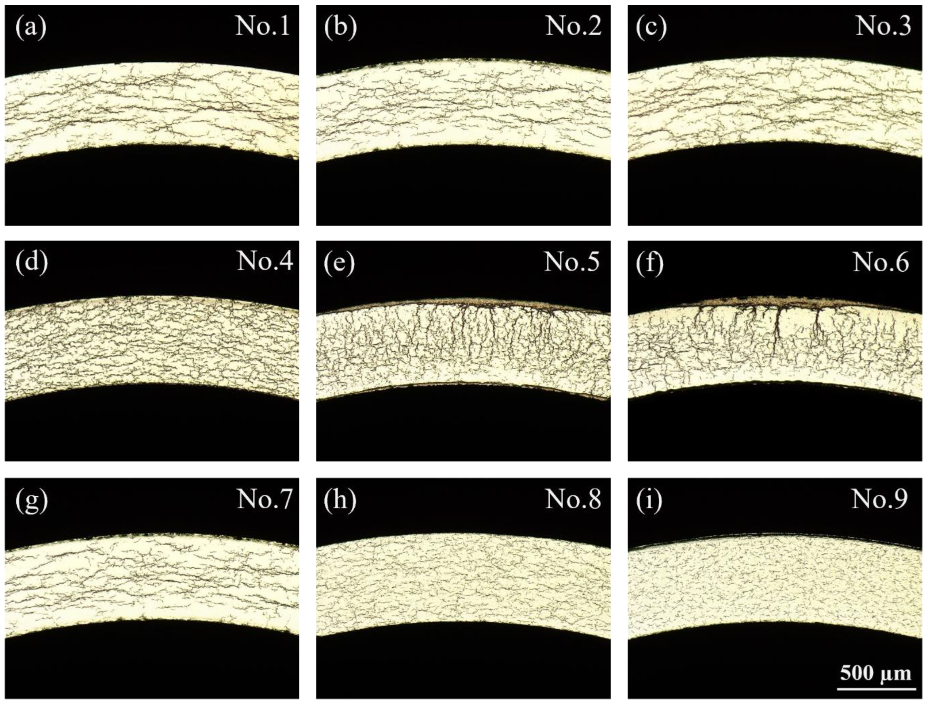
3.3.1. Effect of Heating Rate on Hydride Distribution

Due to the slow cooling rate of 2 °C/min, hydride precipitation in zirconium alloys commonly forms in the δ phase (FCC) [28]. Figure 4 shows the distribution of hydride precipitation in a zirconium matrix after heat treatment at different heating rates. It is particularly evident that the heating rate has a considerable influence on the amount of hydride formation, with sample No. 6 (high heating rate) exhibiting a much higher number of hydrides compared to sample No. 1 (low heating rate). In sample No. 1, hydrides were present as individual clusters (Figure 5(a1)) and were distributed circumferentially. The majority of the hydrides were intra-granular, with a small proportion located at the grain boundaries. The hydrides within adjacent grains connected with each other, forming chain-like trans-granular hydrides. In sample No. 6, hydrides were found to be distributed in “sun spots” along the radial direction of the tube, with a tendency to exist in multiple clusters near the outer wall. The arrangement of hydrides exhibited two forms: one is the stacking of several parallel hydride plates, all oriented in the same direction within clusters; and the other is the stacking of parallel hydride plates with a zirconium matrix visible between them, showing a slightly different orientation to the hydride cluster (Figure 5(c1)). Hydrides and hydride clusters were primarily located within the grains, with some of them also present at grain boundaries, and the outermost hydride of the clusters was inevitably in contact with the grain boundaries. In the vicinity of the tube inner wall, the number of hydrides decreased, and they existed in the form of individual clusters (Figure 5(b1)). Radial hydrides interconnected with circumferential hydrides to form a net-like structure, and the hydrides were distributed both within the grains and at the grain boundaries. The distribution of hydrides within and at grain boundaries is statistically presented in Table 4 (expressed as an area ratio). As the heating rate increased, the proportion of hydrides within the grains significantly decreased, indicating a tendency to precipitate preferentially at the grain boundaries. It should be noted that due to the clustered presence of hydrides on the outer side of the No. 6 sample’s tube wall, where the size of the hydride clusters was similar to the grain size, it was impossible to distinguish their exact location; therefore, they were not included in the statistics.

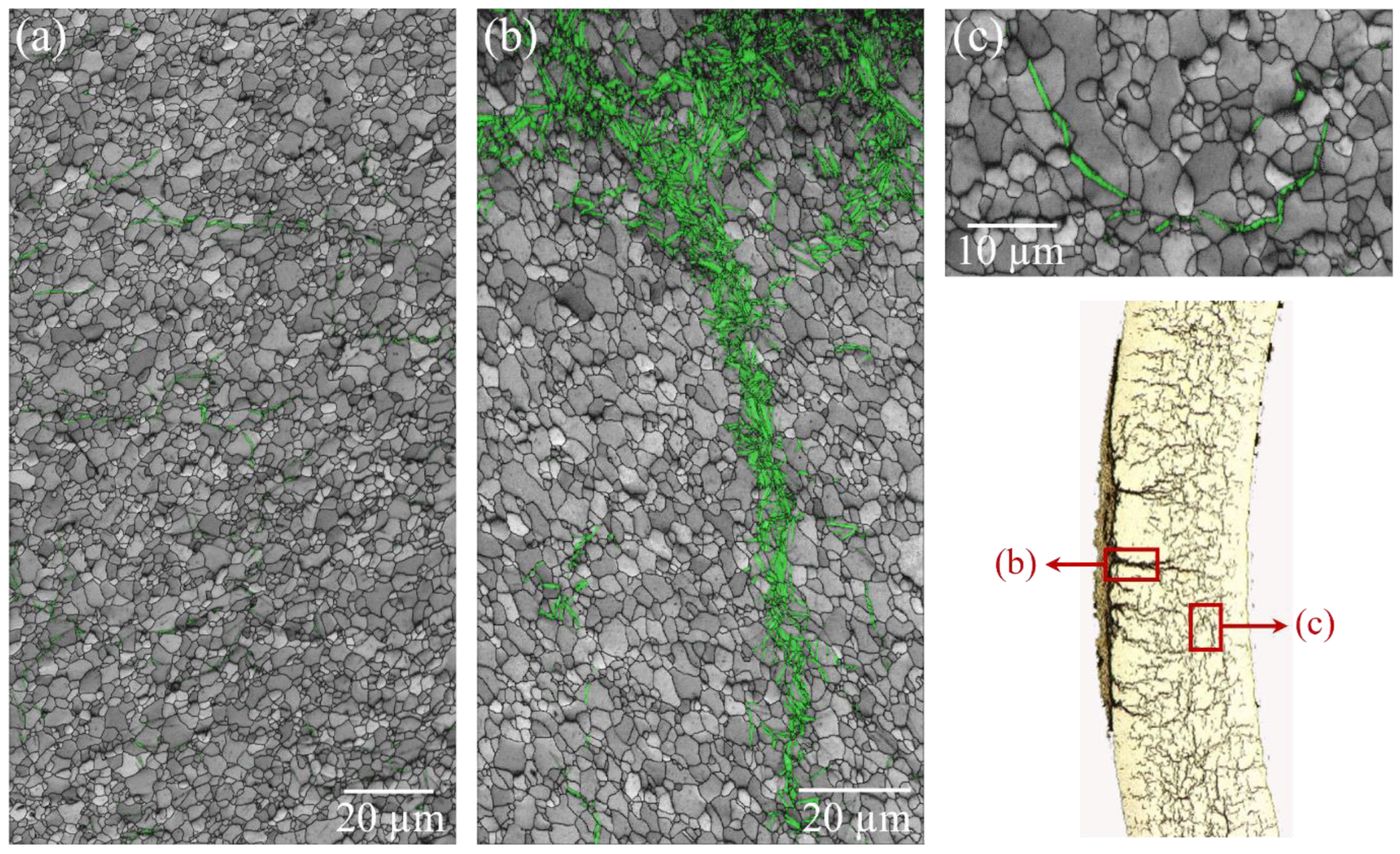
3.3.2. Effect of Heating Rate on Hydride Orientation

The predominant orientation relationship between the hydrides and the zirconium matrix was {0001}α∥{111}δ, <11–20>α∥<110>δ, which is consistent with literature reports [29,30]. Figure 6 illustrates the distribution of the orientation relationship between the zirconium matrix and hydrides, which aligns with {0001}α∥{111}δ, <11–20>α∥<110>δ after heat treatment at different heating rates. With the increase of the heating rate (No. 1 < No. 6-Inside < No. 6-Outside), the proportion of phase boundary between the hydrides and the zirconium matrix, in accordance with orientation relationship, decreased from 81.4% to 72.2%. The heating rate significantly influences the orientation relationship between the hydrides and the zirconium matrix. On the other hand, this may be attributed to the increased proportion of inter-granular hydrides with higher heating rates. Inter-granular hydrides only maintain an orientation relationship with adjacent single side grains [31]. On the other hand, at high heating rates, the hydrides nucleate and grow rapidly, leading to a change in their orientation relationship with the matrix. Therefore, the orientation relationship between the hydrides and the zirconium matrix at high heating rates was characterized in detail. As shown in Figure 7, the interface between the hydrides and the zirconium matrix, which did not correspond to. the {0001}α∥{111}δ, <11–20>α∥<110>δ orientation relationship, was mostly distributed at the grain boundaries. Figure 7b presents a representative single-cluster hydride that does not conform to the aforementioned orientation relationship with the substrate. It can be seen from Figure 7e that H2 was located at the grain boundary of Zr2 and Zr3 grains, with H2 nucleating into Zr3 grain at this boundary. Consequently, there was no obvious orientation relationship between the left side of H2 and the matrix. However, the right side of H2 did not align with the {0001}α∥{111}δ, <11–20>α∥<110>δ orientation relationship, which was due to the overall inconsistency in the orientation of the H2. As seen in Figure 7(b1), a clear gradient change in color can be observed within the H2 strip, indicating that H2 rotated around the c-axis from top to bottom. The orientation relationship between H2 and the matrix is consistent with {0001}α∥{111}δ, but the difference in direction between <11–20>α and <110>δ is around 14°.

4. Discussion

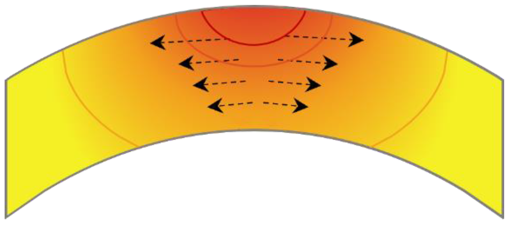
4.1. Effect of Heating Rate on Internal Stress Distribution of Zirconium Alloy Tube

In the scenario of an open-ended zirconium alloy tube, the absence of a pressure gradient across the wall precludes internal–external pressure-induced stresses. However, owing to the distinctive heating method, heat was transferred from the outer wall of the tube to the inner wall, creating a temperature gradient from outside to inside. When the heating rate was slow, there was sufficient time for heat conduction within the tube, resulting in a minimal temperature difference between the inside and outside, and relatively low thermal stress with a more uniform internal stress distribution in the tube. With the increase of the heating rate, the stress gradient over the thickness will become steeper. At a high heating rate, direct heating of the outer side of the tube leads to significant thermal expansion, while delayed heat conduction causes less expansion in the inner layer. This discrepancy leads to a non-uniform stress distribution over the wall thickness. The outer surface of the tube, exposed to elevated temperatures, undergoes substantial thermal expansion. In contrast, the inner surface remains at a relatively lower temperature, exhibiting restricted expansion. This disparity in thermal expansion generates internal constraints on the outer surface. Under these conditions, the outer wall is subject to a triaxial stress state. Specifically, the outer wall experiences radial compressive stresses due to the constraining influence of the less expanded inner wall. Simultaneously, circumferential tensile stresses arise from thermal expansion, while axial stresses are considered negligible. Given that radial stresses are typically minimal, the primary focus is on the development of circumferential tensile stresses, which display a gradient that decreases radially inward from the exterior to the interior of the tube, as illustrated in Figure 8.

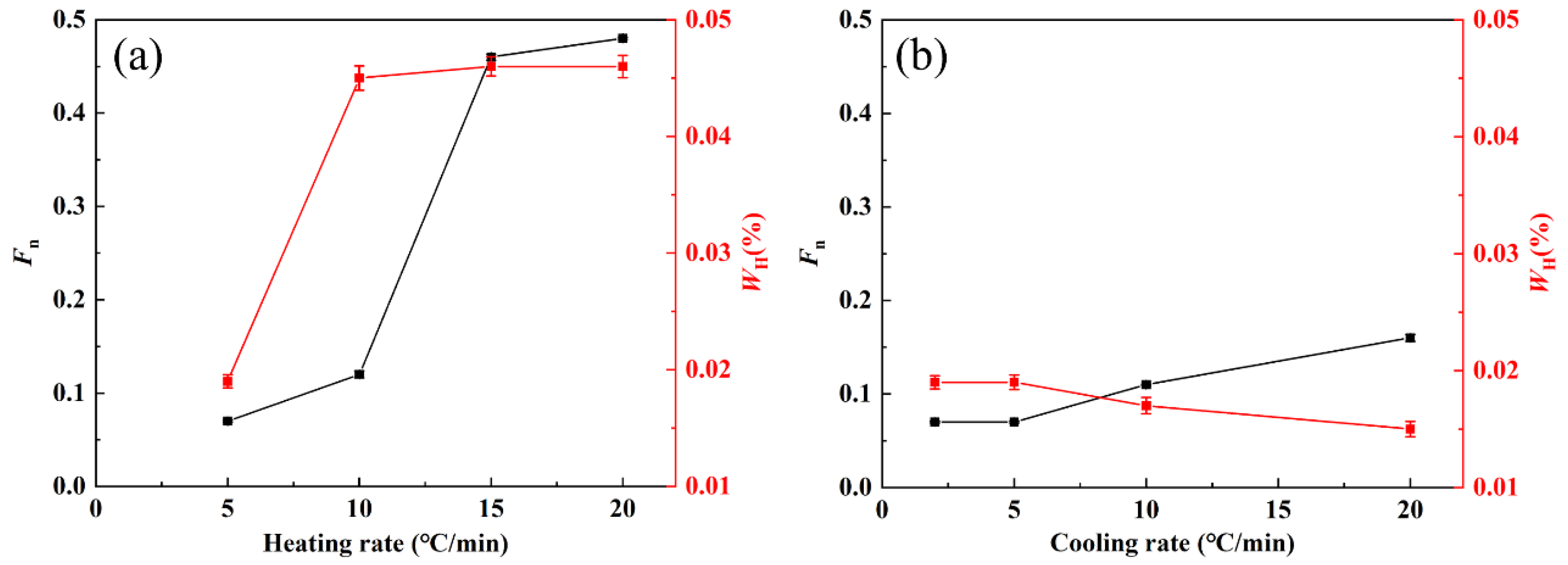
4.2. Effect of Heating Rate on Hydrogen Content

The solubility of hydrogen in zirconium alloys is relatively low, with only a few ppm at room temperature. At 400 °C, the solubility of hydrogen in zirconium is 0.024% [32]. However, in the heat treatment process of the hydrogenation experiment, the heating rate will affect the hydrogen content. As the heating rate increases, the stress gradient along the wall thickness of the tube intensifies. This leads to a rise in steady-state hydrogen diffusion flux and an increase in hydrogen content within the zirconium alloy tube, as shown in Figure 2a [33]. Furthermore, in the presence of high stress gradients, dissolved hydrogen demonstrates the capability to diffuse towards areas of elevated tensile stress [34]. The discrepancy in hydrogen content between the outer and inner walls of cladding tubes at different heating rates (Table 5) serves as evidence supporting this assertion. In the No. 6 sample heated at a rate of 20 °C/min, the hydride content is significantly higher on the outer surface of the cladding tube compared to the inner surface.
When the hydrogen content is low, hydrides exist as individual clusters with a large distance between them (Figure 5a). As the hydrogen content increases, the nucleation position of the hydrides shifts, leading to a decrease in the size of hydride plates and their tendency to aggregate (Figure 5b). A further increase in hydrogen content results in larger hydride plates and increased aggregation (Figure 5c), forming coarse hydride clusters. It is worth nothing that local hydrogen concentration is anticipated to govern the brittleness and failure of cladding hydrides, rather than the average hydrogen concentration [35].

4.3. Effect of Stress Distribution on Hydride Reorientation

In this experiment, the hydrogen content in the zirconium alloy increases as the heating rate rises, from 0.019% to 0.046%. This increase significantly exceeds the solid solubility of hydrogen in the zirconium alloy. According to the hydride precipitation and dissolution as a function of temperature (Figure 9) [36], it is evident that for sample No. 1 with a hydrogen content of 0.019%, hydrogen will be fully dissolved into the matrix during heating and holding processes and subsequently precipitated as a hydride during cooling. However, for samples No. 4, No. 5 and No. 6 with a much higher hydrogen content than TSSP, around 0.033% of hydrogen atoms are dissolved into the matrix during heating and holding processes; the remaining hydrogen exists in hydrides and precipitates again during subsequent cooling processes. Only the dissolved hydrides undergo reorientation upon precipitation [5]. Therefore, radial hydrides in samples 4, 5 and 6 predominantly originate from supersaturated-hydrogen-formed hydrides during heating processes. The hydrides demonstrate a stress orientation effect and tend to redistribute in a direction perpendicular to the tensile stress. As the tube forms a stress distribution during the heating process, as shown in Figure 8, radial hydride formation occurs from outer to inner regions, and the proportion of radial hydrides exhibits a decreasing trend. The observed reduction in the radial hydride ratio near the inner surface of the tube may be attributed to the low hydrogen content and the minimal circumferential stress, which is insufficient to trigger hydride reorientation behavior. As the heating rate escalates, the thermal gradient within the tube wall intensifies, leading to an elevation in the tensile stresses generated by the thermal expansion. Consequently, an increase in the heating rate is accompanied by a rise the fraction of radial hydrides and an enhancement of the hydride orientation parameter for the tube (Figure 2a).
At high heating rates, the hydride in the tube exhibited a macroscopic radial distribution, and the proportion of radial distribution also increased for the single hydride plate. This was accompanied by the disruption of the {0001}α∥{111}δ, <11–20>α∥<110>δ orientation relationship between the hydride and the substrate. The breakdown of crystallographic orientation relationship between the hydride and the matrix is a significant precursor to hydrogen-induced cracking and damage evolution. On the one hand, the fracture of the orientation relationship is attributed to an increase in the proportion of inter-granular hydrides, with inter-granular hydrides exerting a greater influence on the zirconium alloy plasticity than intra-granular ones. On the other hand, due to the rapid nucleation and growth of hydrides, their orientation relationship with the matrix becomes less distinct. The compatibility of hydrides with matrix orientation is poor, leading to stress concentration at the interfaces and facilitating crack initiation and propagation.

5. Conclusions

In this study, the effect of heat treatment on the hydride reorientation behavior under non-stress loading was investigated. The following conclusions can be drawn:
(1)
With an increase in heating rate, the size and proportion of radial hydrides within the zirconium alloy envelope increase, leading to the formation of macroscopic hydrides resembling “sun spots”. Conversely, as the cooling rate increases, uniformly dispersed hydrides are formed.
(2)
The high heating rate induces the cladding tube to form an uneven stress gradient along the heat transfer direction, resulting in hydrogen diffusion to the high-stress region and precipitation perpendicular to the tensile stress direction.
(3)
The hydride and substrate exhibit the orientation relationship {0001}α∥{111}δ, <11–20>α∥<110>δ. As the heating rate increases, the orientation relationship is disrupted, making it easier for cracks to form.

Author Contributions

Investigation, B.H., M.C. and X.L.; Formal analysis, B.H.; Data curation, B.H., M.C. and X.L.; Validation, B.H., X.L. and Y.L.; writing-original draft preparation, B.H. and M.C.; methodology, M.C.; supervision, B.C., Y.L., J.Z. and R.T.; writing-review and editing, B.C. and J.L.; Resources, Y.L., J.Z. and R.T.; conceptualization, J.Z. and R.T.; Funding acquisition, J.L. All authors have read and agreed to the published version of the manuscript.

Funding

This research was funded by the China National Natural Science Foundation (U2067217).

Data Availability Statement

The data presented in this study are available on request from the corresponding author due to privacy.

Conflicts of Interest

Authors Boning Hui, Xinyi Li, Yuli Li, Jun Zhou, and Rongtao Tang are employed by the company Western Energy Materials Technology Co., Ltd. The remaining authors declare that the research was conducted in the absence of any commercial or financial relationships that could be construed as a potential conflict of interest.

References

  1. Kautz, E.; Gwalani, B.; Yu, Z.; Varga, T.; Geelhood, K.; Devaraj, A.; Senor, D. Investigating Zirconium Alloy Corrosion with Advanced Experimental Techniques: A Review. J. Nucl. Mater. 2023, 585, 154586. [Google Scholar] [CrossRef]
  2. Than, Y.R.; Grimes, R.W.; Bell, B.D.C.; Wenman, M.R. Understanding the Role of Fe, Cr and Ni in Zircaloy-2 with Special Focus on the Role of Ni on Hydrogen Pickup. J. Nucl. Mater. 2020, 530, 151956. [Google Scholar] [CrossRef]
  3. Kearns, J.J. Terminal solubility and partitioning of hydrogen in the alpha phase of zirconium, Zircaloy-2 and Zircaloy-4. J. Nucl. Mater. 1967, 22, 292–303. [Google Scholar] [CrossRef]
  4. Simpson, C.J.; Ells, C.E. Delayed hydrogen embrittlement in Zr-2.5 wt % Nb. J. Nucl. Mater. 1974, 52, 289–295. [Google Scholar] [CrossRef]
  5. Chu, H.C.; Wu, S.K.; Kuo, R.C. Hydride reorientation in Zircaloy-4 cladding. J. Nucl. Mater. 2008, 373, 319–327. [Google Scholar] [CrossRef]
  6. Simon, P.A.; Frank, C.; Chen, L.; Tonks, M.R.; Motta, A.T. Quantifying the effect of hydride microstructure on zirconium alloys embrittlement using image analysis. J. Nucl. Mater. 2021, 547, 152817. [Google Scholar] [CrossRef]
  7. Puls, M.P.; Shi, S.; Rabier, J. Experimental studies of mechanical properties of solid zirconium hydrides. J. Nucl. Mater. 2005, 336, 73–80. [Google Scholar] [CrossRef]
  8. Gopalan, A.; Bind, A.K.; Sunil, S.; Murty, T.N.; Sharma, R.K.; Samanta, A.; Soren, A.; Singh, R.N. Effect of radial hydride on room temperature fracture toughness of Zr-2.5Nb pressure tube material. J. Nucl. Mater. 2021, 544, 152681. [Google Scholar] [CrossRef]
  9. Carpenter, G.J.C. The precipitation of γ-zirconium hydride in zirconium. Acta Metall. 1978, 26, 1225–1235. [Google Scholar] [CrossRef]
  10. Carpenter, G.J.C. The dilatational misfit of zirconium hydrides precipitated in zirconium. J. Nucl. Mater. 1973, 48, 264–266. [Google Scholar] [CrossRef]
  11. Jia, Y.-J.; Han, W.-Z. Effect of external stress on hydride reorientation in zirconium. Acta Mater. 2022, 235, 118100. [Google Scholar] [CrossRef]
  12. Simon, P.A.; Aagesen, L.K.; Jokisaari, A.M.; Chen, L.; Daymond, M.R.; Motta, A.T.; Tonks, M.R. Investigation of δ zirconium hydride morphology in a single crystal using quantitative phase field simulations supported by experiments. J. Nucl. Mater. 2021, 557, 153303. [Google Scholar] [CrossRef]
  13. Lin, X.-H.; Beyerlein, I.J.; Han, W.-Z. Annealing cracking in Zr and a Zr-alloy with low hydrogen concentration. J. Mater. Sci. Technol. 2024, 182, 165–175. [Google Scholar] [CrossRef]
  14. Long, F.; Kerr, D.; Domizzi, G.; Wang, Q.; Daymond, M.R. Microstructure characterization of a hydride blister in Zircaloy-4 by EBSD and TEM. Acta Mater. 2017, 129, 450–461. [Google Scholar] [CrossRef]
  15. Liu, S.-M.; Li, S.-H.; Han, W.-Z. Effect of ordered helium bubbles on deformation and fracture behavior of α-Zr. J. Mater. Sci. Technol. 2019, 35, 1466–1472. [Google Scholar] [CrossRef]
  16. Hong, X.Y.; Ma, F.Q.; Zhang, J.Y.; Du, D.H.; Tian, H.; Xu, Q.; Zhou, J.; Gong, W.J. Effect of hydride orientation on tensile properties and crack formation in zirconium alloy cladding tubes. J. Nucl. Mater. 2024, 596, 155120. [Google Scholar] [CrossRef]
  17. Auzoux, Q.; Bouffioux, P.; Machiels, A.; Yagnik, S.; Bourdiliau, B.; Mallet, C.; Mozzani, N.; Colas, K. Hydride reorientation and its impact on mechanical properties of high burn-up and unirradiated cold-worked stress-relieved Zircaloy-4 and ZirloTM fuel cladding. J. Nucl. Mater. 2022, 568, 153893. [Google Scholar] [CrossRef]
  18. Plyasov, A.A.; Novikov, V.V.; Devyatko, Y.N. A Review of Hydride Reorientation in Zirconium Alloys for Water-Cooled Reactors. Phys. At. Nucl. 2020, 83, 1407–1424. [Google Scholar] [CrossRef]
  19. Woo, D.; Lee, Y. Understanding the mechanical integrity of Zircaloy cladding with various radial and circumferential hydride morphologies via image analysis. J. Nucl. Mater. 2023, 584, 154560. [Google Scholar] [CrossRef]
  20. Bang, S.; Kim, H.; Noh, J.; Keum, K.; Lee, Y. Temperature-dependent axial mechanical properties of Zircaloy-4 with various hydrogen amounts and hydride orientations. Nucl. Eng. Technol. 2022, 54, 1579–1587. [Google Scholar] [CrossRef]
  21. Kim, D.; Woo, D.; Lee, Y. Radial hydride fraction with various rod internal pressures and hydrogen contents for Zr-Nb alloy cladding tube. J. Nucl. Mater. 2022, 572, 154036. [Google Scholar] [CrossRef]
  22. Kearns, J.J.; Woods, C.R. Effect of texture, grain size, and cold work on the precipitation of oriented hydrides in Zircaloy tubing and plate. J. Nucl. Mater. 1966, 20, 241–261. [Google Scholar] [CrossRef]
  23. Alam, A.; Hellwig, C. Cladding Tube Deformation Test for Stress Reorientation of Hydrides. In Zirconium in the Nuclear Industry: 15th International Symposium; ASTM International: West Conshohocken, PA, USA, 2009; 136p. [Google Scholar]
  24. Kim, J.-S.; Kim, Y.-J.; Kook, D.-H.; Kim, Y.-S. A study on hydride reorientation of Zircaloy-4 cladding tube under stress. J. Nucl. Mater. 2015, 456, 246–252. [Google Scholar] [CrossRef]
  25. Chu, L.H.; Yuan, G.H.; Yao, M.Y.; Gao, B.; Xv, S.T.; Zhou, B.X. Effect of Impurity Elements (C, Si) on Microstructure and Corrosion Resistance of Zircaloy-4 Sheet. Rare Met. Mater. Eng. 2020, 49, 3338–3346. [Google Scholar]
  26. Hui, B.N.; Liang, W.; Zhou, J.; Liu, H.M.; Wen, H.M.; Li, F.; Shang, X.D.; Wei, Q.; Liu, J.; Yang, Y.H. The Invention Relates to a High Pressure Gas Permeating Device and Method for Nuclear Zirconium Alloy Material. CN202210587863.8, 26 May 2022. [Google Scholar]
  27. ASTM B811-13(2022)e1; B10 Committee, Wrought Zirconium Alloy Seamless Tubes for Nuclear Reactor Fuel Cladding. ASTM International: West Conshohocken, PA, USA, 2022. [CrossRef]
  28. Bradbrook, J.S.; Lorimer, G.W.; Ridley, N. The precipitation of zirconium hydride in zirconium and zircaloy-2. J. Nucl. Mater. 1972, 42, 142–160. [Google Scholar] [CrossRef]
  29. Maric, M.; Thomas, R.; Davis, A.; Lunt, D.; Donoghue, J.; Gholinia, A.; De Graef, M.; Ungar, T.; Barberis, P.; Bourlier, F.; et al. Identification, classification and characterisation of hydrides in Zr alloys. Scr. Mater. 2024, 238, 115768. [Google Scholar] [CrossRef]
  30. Li, J.; Wang, Z.; Wu, H.; Chen, G. Microstructural and crystallographic analysis of hydride reorientation in a zirconium alloy cladding tube. J. Nucl. Mater. 2020, 537, 152232. [Google Scholar] [CrossRef]
  31. Qin, W.; Kumar, N.A.P.K.; Szpunar, J.A.; Kozinski, J. Intergranular δ-hydride nucleation and orientation in zirconium alloys. Acta Mater. 2011, 59, 7010–7021. [Google Scholar] [CrossRef]
  32. UNE, K.; Ishimoto, S. Terminal Solid Solubility of Hydrogen in Unalloyed Zirconium by Differential Scanning Calorimetry. J. Nucl. Sci. Technol. 2004, 41, 949–952. [Google Scholar] [CrossRef]
  33. Ells, C.E.; Simpson, C.J. Hydrogen in Metals; ASM: Metals Park, OH, USA, 1974. [Google Scholar]
  34. Plus, M.P. The Effect of Hydrogen and Hydrides on the Integrity of Zirconium Alloy Components: Delayed Hydride Cracking; Springer: London, UK, 2012. [Google Scholar]
  35. Nantes, K.R.B.; Jin, M.; Motta, A.T. Modeling hydrogen localization in Zircaloy cladding subjected to temperature gradients. J. Nucl. Mater. 2024, 589, 154853. [Google Scholar] [CrossRef]
  36. Motta, A.T.; Capolungo, L.; Chen, L.-Q.; Cinbiz, M.N.; Daymond, M.R.; Koss, D.A.; Lacroix, E.; Pastore, G.; Simon, P.-C.A.; Tonks, M.R.; et al. Hydrogen in zirconium alloys: A review. J. Nucl. Mater. 2019, 518, 440–460. [Google Scholar] [CrossRef]
Figure 1. Hydride morphologies under different heat treatment conditions. (a) No.1; (b) No.2; (c) No.3; (d) No.4; (e) No.5; (f) No.6; (g) No.7; (h) No.8; (i) No.9.
Metals 14 01126 g001
Figure 2. Hydride orientation factor and hydrogen content under different heat treatments: (a) heating rate and (b) cooling rate.(The black line represents Fn and the red line represents WH).
Metals 14 01126 g002
Figure 3. IPF map (ac) and grain size (a1c1) of zirconium alloy matrix after heat treatment at different heating rates: (a) sample No. 0; (b) sample No. 1; and (c) sample No. 6.
Metals 14 01126 g003
Figure 4. Distribution of hydrides in zirconium matrix after heat treatment at different heating rates: (a) sample No. 1; (b) outside the tube wall of sample No. 6; and (c) inside the tube wall of sample No. 6.
Metals 14 01126 g004
Figure 5. Morphology of hydrides in zirconium matrix after heat treatment at different heating rates: (a,a1) sample No. 1; (b,b1) inside the tube wall of sample No. 6; and (c,c1) outside the tube wall of sample No. 6.
Metals 14 01126 g005
Figure 6. Distribution of {0001}α∥{111}δ, <11–20>α∥<110>δ orientation relationship between zirconium matrix and hydrides after heat treatment at different heating rates: (a) outside the tube wall of sample No. 6; (b) sample No. 1; (c) inside the tube wall of sample No. 6; (d) the pole figure projections of hydrides and its matrix; and (e) the proportion statistics of {0001}α∥{111}δ, <11–20>α∥<110>δ orientation relationship.
Metals 14 01126 g006
Figure 7. The orientation relationship between zirconium matrix and hydrides of sample No. 6: (a) distribution of grain boundaries, phase boundaries and the interface of hydrides and matrix consistent with {0001}α∥{111}δ, <11–20>α∥<110>δ orientation relationship; (b) the white frame in (a); (b1) the corresponding IPF map; (c) the PF map of H2 and Zr3; (d) the cell diagram at different positions of H2; and (e) the cell diagram of Zr matrix in (b).
Metals 14 01126 g007
Figure 8. Schematic diagram of internal temperature and stress distribution of zirconium alloy tube at high heating rate.(Color serves as an indicator of temperature; the darker the color, the higher the temperature. The arrow represents both the direction and magnitude of stress. A longer arrow signifies a greater level of stress.)
Metals 14 01126 g008
Figure 9. TSSD (blue line) and TSSP (red line) in zirconium alloys.
Metals 14 01126 g009
Table 1. Chemical composition of Zr–Sn–Nb alloy specimens (wt.%).
ZrSnNbFeO
Matrix1.0%1.0%0.3%0.11%
Table 2. Heat treatment parameter of hydrogenation experiment.
SampleHeating Rate (°C/min)Holding Temperature (°C)Hold Time (h)Cooling Rate (°C/min)
No. 1540022
No. 2550022
No. 3560022
No. 41040022
No. 51540022
No. 62040022
No. 7540025
No. 85400210
No. 95400220
Table 3. Hydride orientation factor ( F n 45 ) and hydrogen content (WH) under different heat treatments.
SampleHeating Rate (°C/min)Cooling Rate (°C/min) F n 45 WH (%)
No. 1520.071 ± 0.00100.0190 ± 0.0006
No. 41020.122 ± 0.00360.0451 ± 0.0010
No. 51520.461 ± 0.00320.0460 ± 0.0008
No. 62020.482 ± 0.00100.0464 ± 0.0010
No. 7550.070 ± 0.00120.0190 ± 0.0006
No. 85100.112 ± 0.00060.0170 ± 0.0007
No. 95200.159 ± 0.00360.0149 ± 0.0007
Table 4. Positions of hydrides in zirconium matrix after heat treatment at different heating rates.
SampleIntra-Granular ProportionInter-Granular Proportion
No. 167.19%32.80%
No. 6-Inside47.33%52.67%
Table 5. Area ratio of inner and outer hydride of zirconium alloy tube at different heating rates.
Sample
Region
No. 1No. 4No. 6
Outside9.38%14.05%23.04%
Inside10.58%12.25%10.77%
Disclaimer/Publisher’s Note: The statements, opinions and data contained in all publications are solely those of the individual author(s) and contributor(s) and not of MDPI and/or the editor(s). MDPI and/or the editor(s) disclaim responsibility for any injury to people or property resulting from any ideas, methods, instructions or products referred to in the content.

