Abstract
The interconnecting solder is a key control factor for the reliability of electronic power packaging because it highly affects the junction temperature of insulated-gate bipolar transistor (IGBT) modules and is prone to plasticity, creep, and other failure behaviors under temperature-change environments. In this paper, the interconnecting performance and fatigue life of five different kinds of solders such as SAC305, sintered silver, Au80Sn20, sintered copper, and pure In under direct current (DC), power cycle, and electro-thermal coupling complex environments were studied based on electro-thermal multi-physical field coupling finite element simulation method, respectively. Results show that the sintered silver owns the most outstanding thermal reliability and the DC operating junction temperature of the IGBT module after utilizing sintered silver solder is only 90.2 °C, which is nearly 15 °C lower than that of the IGBT module utilizing SAC305 solder. Furthermore, in the power cycle reliability test, the fatigue life of Au80Sn20 solder reaches a maximum of 3.26 × 10⁷ cycles while the life of indium presents only 5.85 × 10³ cycles, a difference of nearly four orders of magnitude. Finally, under the complex environment of electro-thermal coupling, the fatigue life of Au80Sn20 solder is also the largest at 1.9 × 10⁶ cycles, while the smallest life of solder becomes SAC305 solder at 4.44 × 10² cycles. The results of this paper can provide a theoretical basis for solder selection and life prediction of the IGBT module, which is of great significance in improving the reliability of power electronic packaging.
1. Introduction
As one of the most important power semiconductor devices, IGBT has been widely used in many fields such as smart grid, household appliances, electric vehicles, and so on. Its reliability is highly related to the reliability of the whole electronic system.
The causes of IGBT damage usually include thermal fatigue, mechanical fatigue, corrosion, and other factors, among which thermal fatigue is the most common. A research institution of the United States Air Force has conducted probability statistics on the failure causes of electronic equipment, and the results show that the failure caused by temperature is the main reason for the failure of electronic equipment, nearly 40% [1]. The failure mechanism is usually due to the difference in the coefficient of thermal expansion between the solder and substrate. In the environment of temperature change, the solder itself is stimulated to produce thermal stress and plastic, creep, and elastic strain behavior. The accumulation of plastic deformation and creep damage over a long period of time leads to holes or cracks in the solder, resulting in solder failure [2].
Based on the mechanical stress, strain, and creep parameters of solder, various empirical models are proposed to predict the fatigue life of power devices. Among them, Coffin–Manson [3,4], Engelmaier [5], Solomon [6], and other models are commonly used to evaluate the reliability of thermal cycling of electronic devices. In addition, various constitutive equations, ranging from viscoplastic models to pure time-varying creep models, have been proposed to simulate solder behavior. There have been extensive studies in the literature to evaluate the thermal fatigue life of solder in electronic devices subjected to temperature cycling.
The finite element method is a convenient choice for studying and improving various application designs. The FEM-based simulation can significantly save time and cost in IGBT device development. The fatigue life test usually takes time; therefore, researchers often use the finite element method to predict the fatigue life of equipment and can usually obtain satisfactory prediction results [7].
With the densification of electronic power devices and the increase in power and operating temperature, it has become more and more important to study the reliability of solder joints under high temperatures, currents, and mechanical stresses. SAC305 solder has been widely used in IGBT modules due to its low cost and high melting point compared to other tin-based solders. Yang K et al. used finite element simulation and the J-integral method to evaluate the power cycling for fatigue crack extension [8]. Sintered silver has found more applications in wide-band semiconductor devices due to its good thermal conductivity and high melting point [9]. Currently, Au80Sn20 solder is mainly used in semiconductor lasers and LEDs. G. Zhang et al. used an accelerated power cycling method to predict the thermal fatigue life of bonding materials for encapsulated HB LED chips. The results show that Au80Sn20 eutectic has a longer thermal fatigue life than silver paste at the same thermal fatigue stress temperature difference [10]. Low-temperature copper sintering joining technology has been increasingly emphasized in high-power electronic device packaging due to its low material cost, good electrical conductivity, good thermal conductivity, low-temperature joining process, and high use of temperature [11]. Indium solder not only has the basic advantages of soft solder but also has high reliability of solder joints and excellent wettability. In this paper, the finite element of the 3D model of the IGBT half-bridge module was established, and the junction temperature and stress of IGBT with five different solders were compared under DC operation. Then, combined with the Anand mechanical constitutive model and the Coffin Manson fatigue life model, the solder layer life and failure position were calculated, respectively, under the complex power cycle and electro-thermal coupling environment, and, finally, the life of these five kinds of solders was comparatively analyzed.
2. Modelling Parameters and Methods
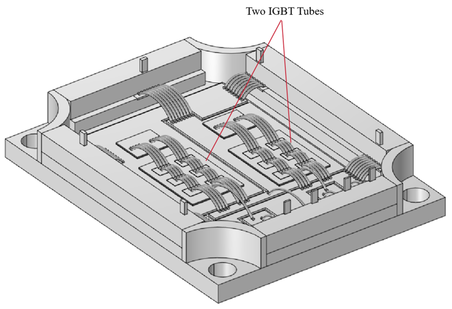
We modeled the IGBT module with Solidworks (SOLIDWORKS 2021, Waltham, MA, USA) and imported it into Comsol Multiphysics (COMSOL Multiphysics 6.0, Stockholm, Sweden). The three-dimensional finite element model is shown in Figure 1. Table 1 lists the detailed geometric parameters of the model. The module is composed of two diodes and two IGBTs. The geometric structure from bottom to top is, successively, copper substrate, lower solder layer, DBC copper clad plate (copper is OFE copper), upper solder layer, and silicon substrate, and the pins and bonding wires are made of aluminum.

Figure 1.
Three-dimensional finite element model of the IGBT half-bridge module.

Table 1.
Geometric parameters of IGBT module.
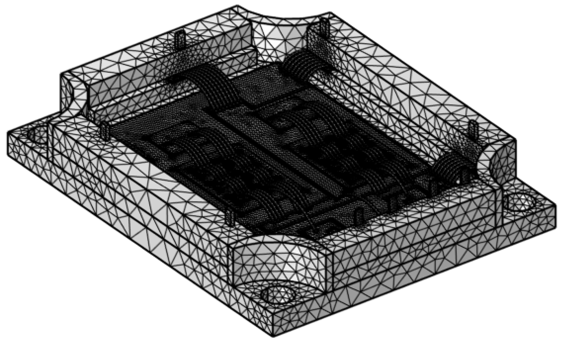
In the meshing process of the model, we adopt the free tetrahedral meshing element to ensure the precise representation of the geometric structure. The total number of components is 259,054, of which the minimum mesh cell size is 0.5 mm, as shown in Figure 2. The degree of mesh refinement usually has a positive correlation with the accuracy of the simulation results; however, over-refinement of the mesh may lead to the waste of resources and significantly increase the calculation time. Therefore, on the basis of fully considering the calculation time cost, the mesh is properly refined to balance the relationship between calculation efficiency and simulation accuracy. This modeling and meshing approach provides a solid foundation for subsequent thermal performance analysis, ensuring that we can obtain high-quality simulation results to evaluate the thermal management performance and reliability performance of the module under different operating conditions.
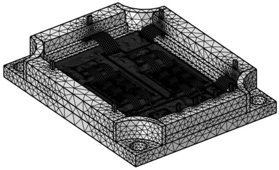
Figure 2.
IGBT module mesh unit.
2.1. DC Reliability Modelling
Due to the different thermal conductivity of the five types of solder, this section adopts the finite element analysis method of coupling electric, thermal, and multi-physics fields to simulate the junction temperature of IGBT modules under different solder materials. Current field: Apply a current density of 3 A/mm2 to the collector pin of the upper IGBT and ground the emitter pin of the lower IGBT. Thermal field: As this model does not add a heat sink at the bottom of the substrate, a convective heat transfer coefficient of 20,000 W/m2·K is set on the bottom of the substrate, and a convective heat transfer coefficient of 125 W/m2·K is set around the substrate and plastic casing. Force field: Set fixed constraints on the bottom surface of the substrate. In addition, multiple physical field coupling conditions such as electromagnetic heat and thermal expansion were considered. The material parameters used for the geometric structure of the finite element model in this article are shown in Table 2 and Table 3 [12,13,14,15,16,17].
Table 2.
Material properties of various materials.
Table 3.
Young’s modulus of sintered silver.
2.2. Power Cycling Reliability Modelling
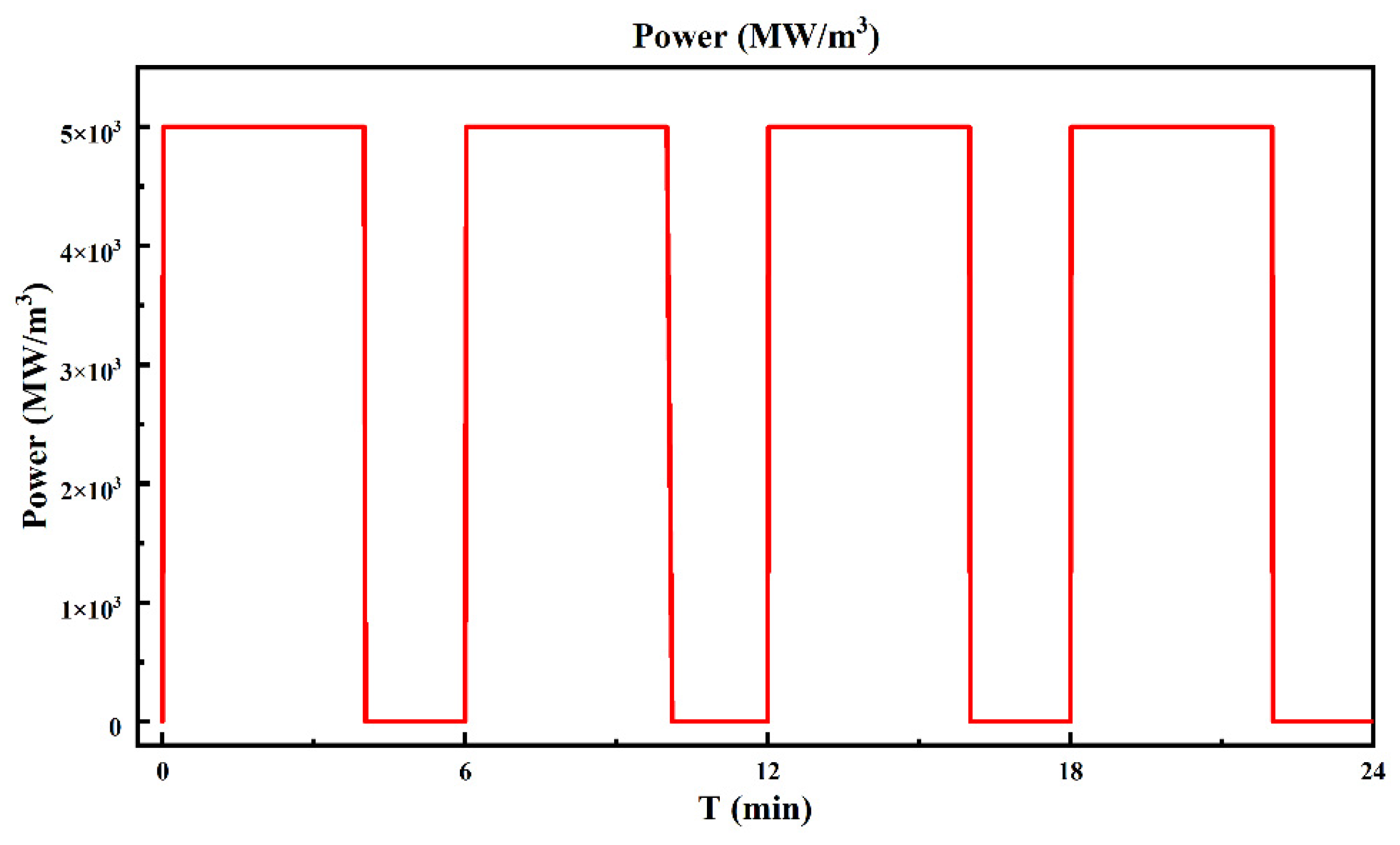
The junction temperature of IGBT modules is undoubtedly an important criterion for reliability. From the previous section, we can compare the thermal reliability of five types of solder materials. In addition, based on this, power cycling tests are conducted on IGBT modules to simulate the fatigue life of the solder layer in the module. The power load is shown in Figure 3, with a peak power of 5 GW/m3 and a duty cycle of approximately 66.7%. One cycle lasts for 6 min, for a total of four cycles.
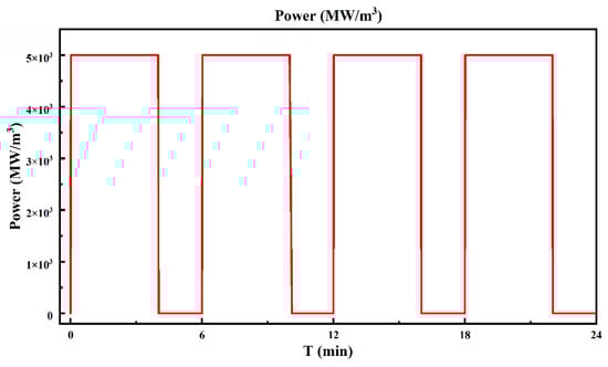
Figure 3.
Power cycle load for 4 cycles.
In this study, it is assumed that all materials except for solder exhibit various elastic behaviors. Use the Anand viscoplastic constitutive model to simulate the viscoplastic changes of solder, which considers the inelastic strain during deformation and the creep behavior over time. The flow equation of the Anand model that relates to the inelastic strain rate is as follows [18]:
where is the pre-exponential factor, is the activation energy, is the strain rate sensitivity, is the temperature, is the stress multiplier, is the universal gas constant, is the deformation resistance, and is the equivalent von Mises stress. Additionally, the evolution equation for the internal variable is given by [18]:
where is the time derivative of deformation resistance, is associated with dynamic hardening and recovery, and its initial value is which is deformation hardening–softening constant, is the strain rate sensitivity exponent of hardening, is saturation coefficient, and and n are material constants. Composed of nine parameters, Table 4 lists the Anand model parameters required for five types of solder materials. Due to the proximity between the upper solder layer and the IGBT chip, the temperature is basically the same, and the upper solder layer is more prone to failure. Therefore, this article focuses on the reliability of the upper solder layer.
Table 4.
Anand model parameters for five different solders.
Based on the generalized fatigue damage law of metal materials, the Coffin–Manson model based on plastic deformation is used to predict the service life of solder joints. Suitable for low-cycle fatigue analysis caused by temperature loads. The basic formula is as follows [19]:
where is the plastic strain range; is fatigue toughness coefficient; C is fatigue toughness index; is the number of failure cycles. Table 5 lists the parameters required for the five solder C-M models. The model parameters for the five solders are shown in Table 5 [13,14,15,16,17].
Table 5.
Coffin–Manson model parameters for five different solders.
2.3. Electro-Thermal Coupling Complex Reliability Modelling
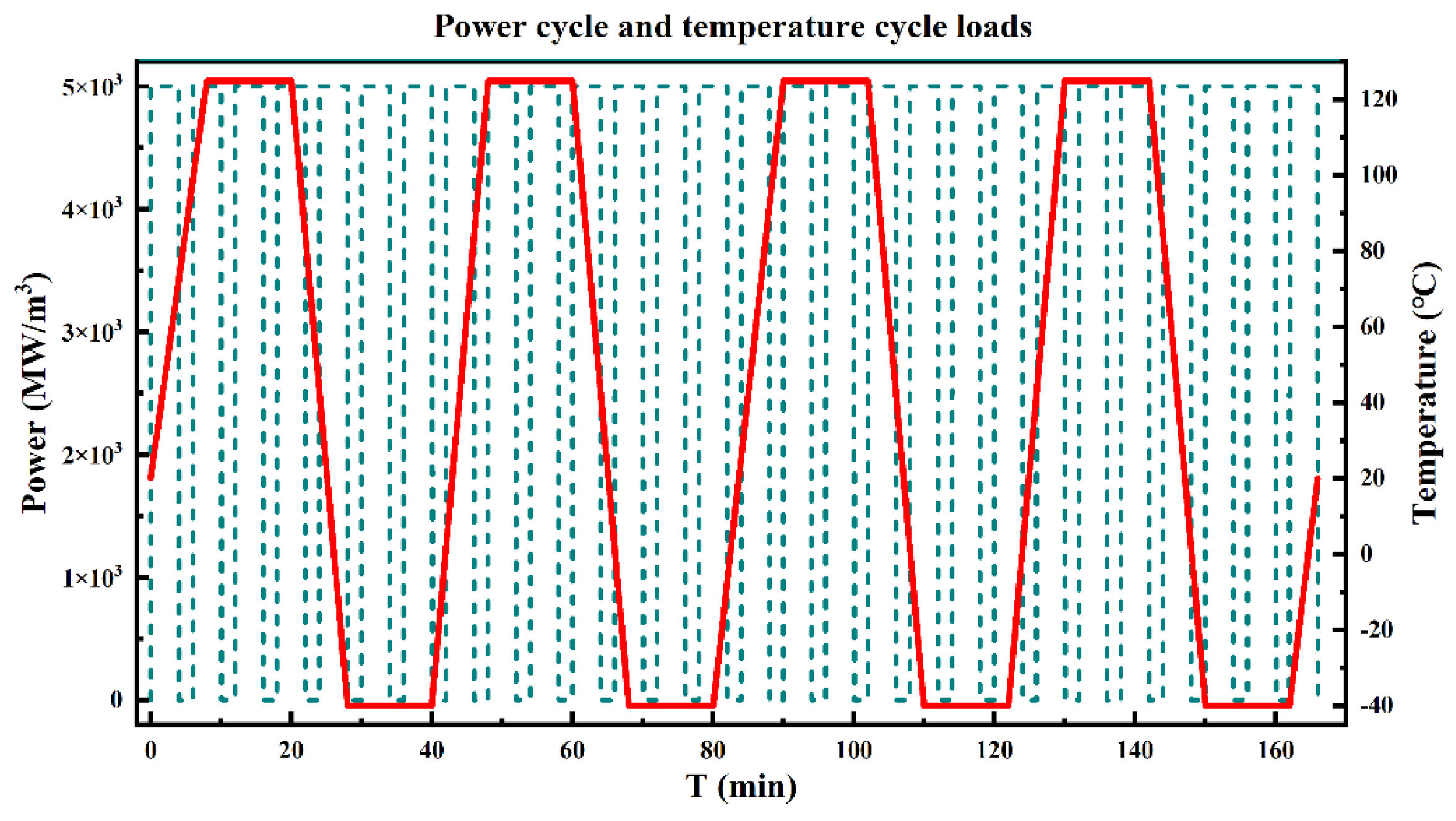
Power cycle (PC) and temperature cycle (TC) have been widely used as the most common testing methods for IGBT module reliability. The former applies pulse current to the IGBT to cause temperature changes in the bonding wire solder joints (referred to as bonding points) and chip solder layers; the latter uses an environmental testing chamber to heat and cool the IGBT as a whole, causing temperature changes in the entire module [20,21,22,23,24,25,26,27]. Although many studies have used the above two methods for reliability testing, there are few studies that combine the two testing methods. In the previous section of this article, a simulation was conducted on the power cycling test of IGBT modules. Based on this, the temperature field of environmental changes was introduced to simulate the lifespan of IGBT in complex environments with thermal electric coupling. Except for the temperature load, other boundary conditions are set the same as in Section 2.2, and Figure 4 shows the load applied in this section. Simulate the IGBT module to turn on and off under environmental changes, with an initial ambient temperature of 20 °C, a rise and fall rate of 15 °C/min, and a holding time of 10 min. There are a total of four cycles.
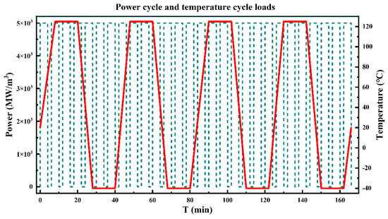
Figure 4.
Power cycle and temperature cycle loads.
3. Results and Discussion
3.1. DC Reliability Analysis
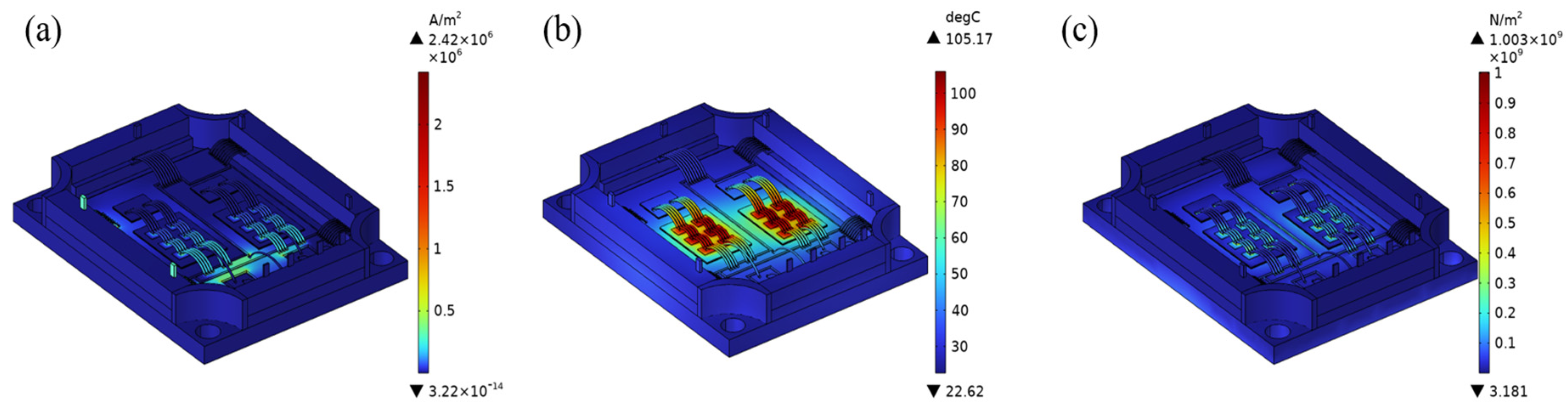
IGBT modules generate a large amount of Joule heat during DC operation, which in turn generates thermal stresses and leads to reliability problems in the solder. In this section, the current density distribution, temperature distribution, and stress distribution of the IGBT module are simulated using SAC305 solder as an example, as shown in Figure 5.

Figure 5.
IGBT module: (a) current density distribution, (b) temperature distribution, (c) stress distribution.
From Figure 5a, it can be seen that the bonding wire near the IGBT module has a higher current density, which will inevitably lead to an increase in the junction temperature due to Joule heat, which is also confirmed in Figure 5b, where the junction temperature of the IGBT module is significantly elevated to 105 °C, which also, in turn, generates a huge amount of thermal stress, and, in Figure 5c, it can be seen that the bonding wire creates a problem of stress concentration in the bonding to the IGBT module which may result in the bonding wire falls off, in addition to the solder layer is affected by the temperature will also have reliability problems. Therefore, it is necessary to choose a solder with better thermal conductivity to reduce the junction temperature and improve reliability.
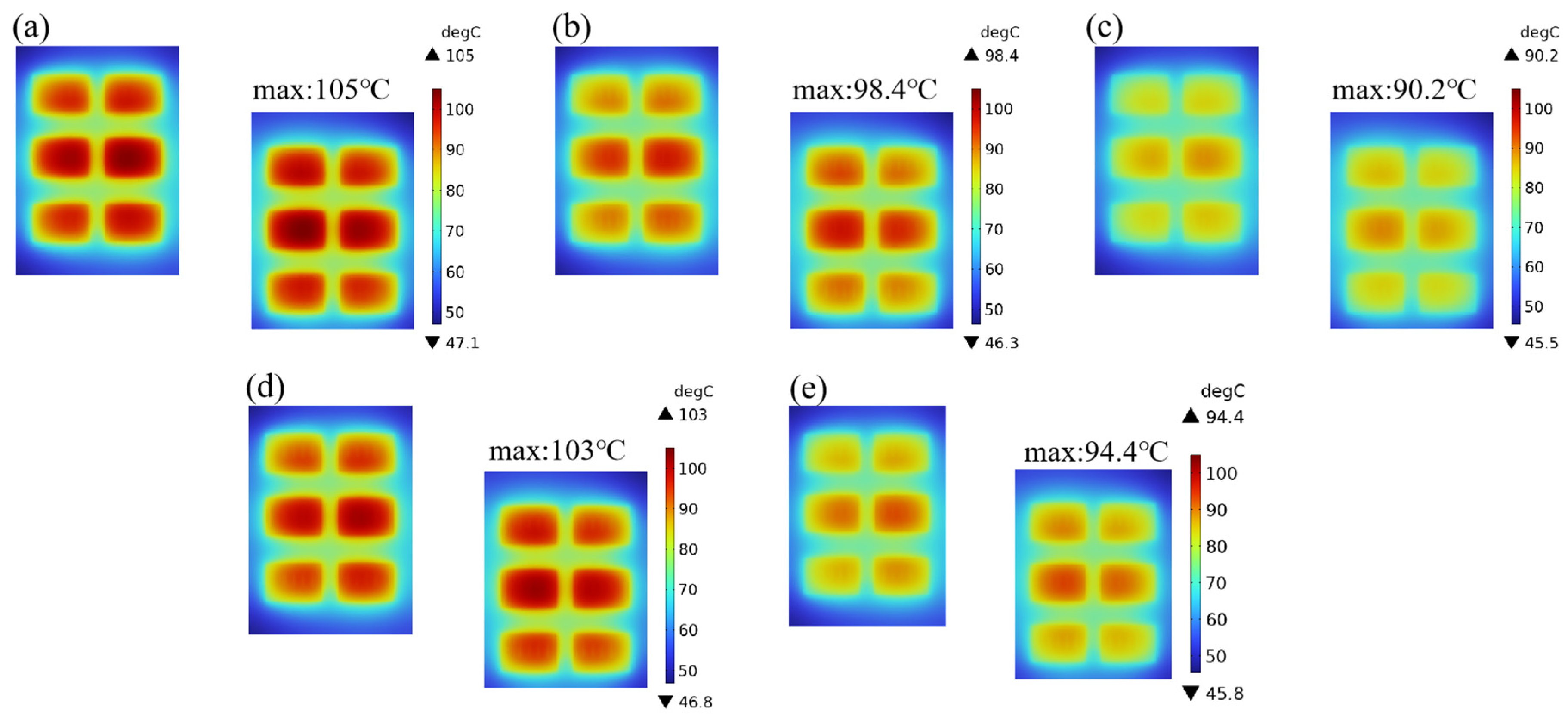
Figure 6 demonstrates the junction temperature distribution of the IGBT chip under different solder materials. It is obvious from the figure that the steady state junction temperature of the IGBT chip is the lowest when using solder-sintered silver, reaching 90.2 °C, which reflects the significant advantage of silver-sintered material in terms of thermal conductivity performance. The high thermal conductivity of silver greatly improves the heat conduction efficiency, thereby effectively reducing the operating temperature of the chip and enhancing its thermal management capability. The thermal conductivity of sintered copper is second only to that of sintered silver; therefore, its steady-state junction temperature is not much different from the results of silver sintering, showing good thermal performance. However, the relatively poor thermal conductivity of SAC305 solder and Au80Sn20 solder results in the steady-state junction temperatures of the IGBT chip being as high as 105 °C and 103 °C, respectively, which suggests that they are less thermally reliable in high-temperature environments, making the devices susceptible to the risk of thermal stress-induced failures. In addition, the thermal conductivity of indium solder is in between the above five solder materials, and although its steady-state junction temperature of 98.4 °C is slightly lower than that of some of the solders, it is still relatively high and exhibits weak thermal reliability. This series of data clearly indicates that when selecting solder materials, their thermal conductivity has a significant impact on the junction temperature as well as the overall thermal reliability of the IGBT module, thus providing an important theoretical basis for future material selection and design optimization.
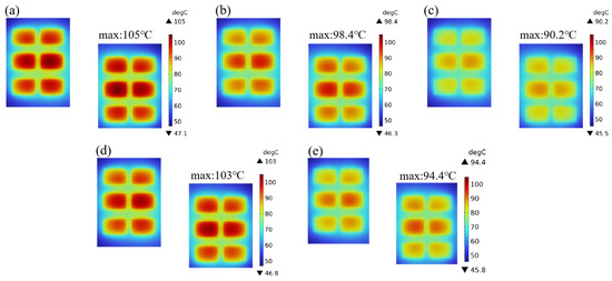
Figure 6.
Junction temperature distribution of two IGBT chips (as Figure 1) under five different solders: (a) SAC305, (b) In, (c) sintered silver, (d) Au80Sn20, (e) sintered copper.
3.2. Power Cycling Reliability Analysis
The power cycle test is an important reliability test, one of its main purposes is to assess module life and establish a module life model. The root cause of power module failure is the mismatch of thermal expansion coefficient [28,29]. Due to the high time cost required for similar aging tests in practice, finite element simulation is a good choice. Studies have shown that interface cracks between chips and solder layers first appear at the edge of the solder layer and then propagate to the center of the solder layer [30].
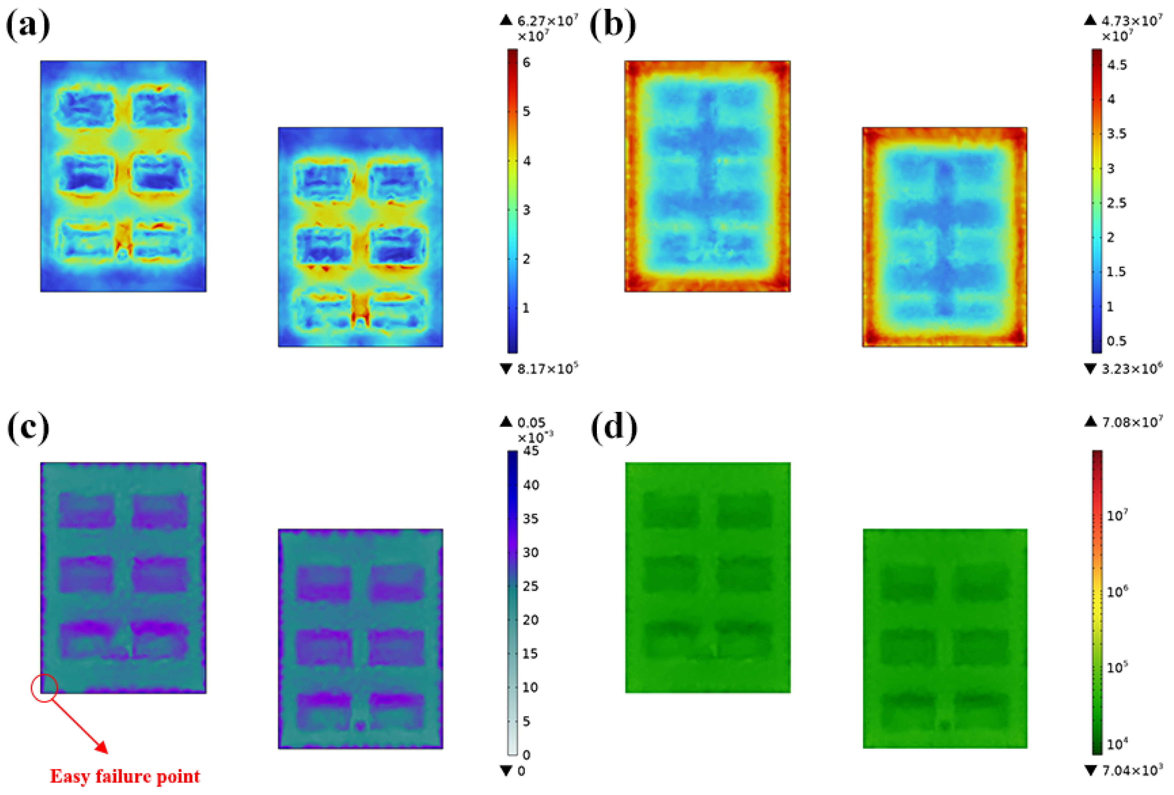
This section also takes SAC305 as an example for analysis. From Figure 7a,b, it can be seen that when the IGBT is turned on, stress is concentrated at the bonding wire and chip bonding position. When the IGBT is turned off, stress is concentrated at the edge of the solder layer. Due to the gradual accumulation of the viscoplastic strain with power cycling, the last minute was selected to observe the distribution of viscoplastic strain in the solder. From Figure 7c, it can be seen that the viscoplastic strain is highest at the edge of the solder and the connection between the bonding wire and the chip, making it most prone to delamination cracking. Figure 7d shows the lifespan distribution of the solder, which corresponds to the location of the maximum viscoplastic strain. It can be seen from the figure that the lifespan of the solder edge and the connection between the bonding wire and the chip is the smallest and most prone to failure.
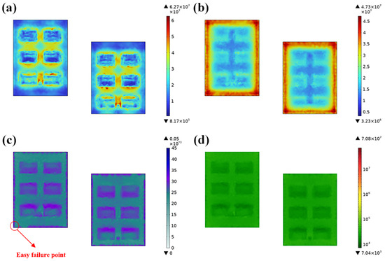
Figure 7.
Stress distribution of upper solder layer: (a) open State at 20 min, (b) closed state at 24 min, (c) last minute viscoplastic strain distribution, (d) distribution of failure cycles.
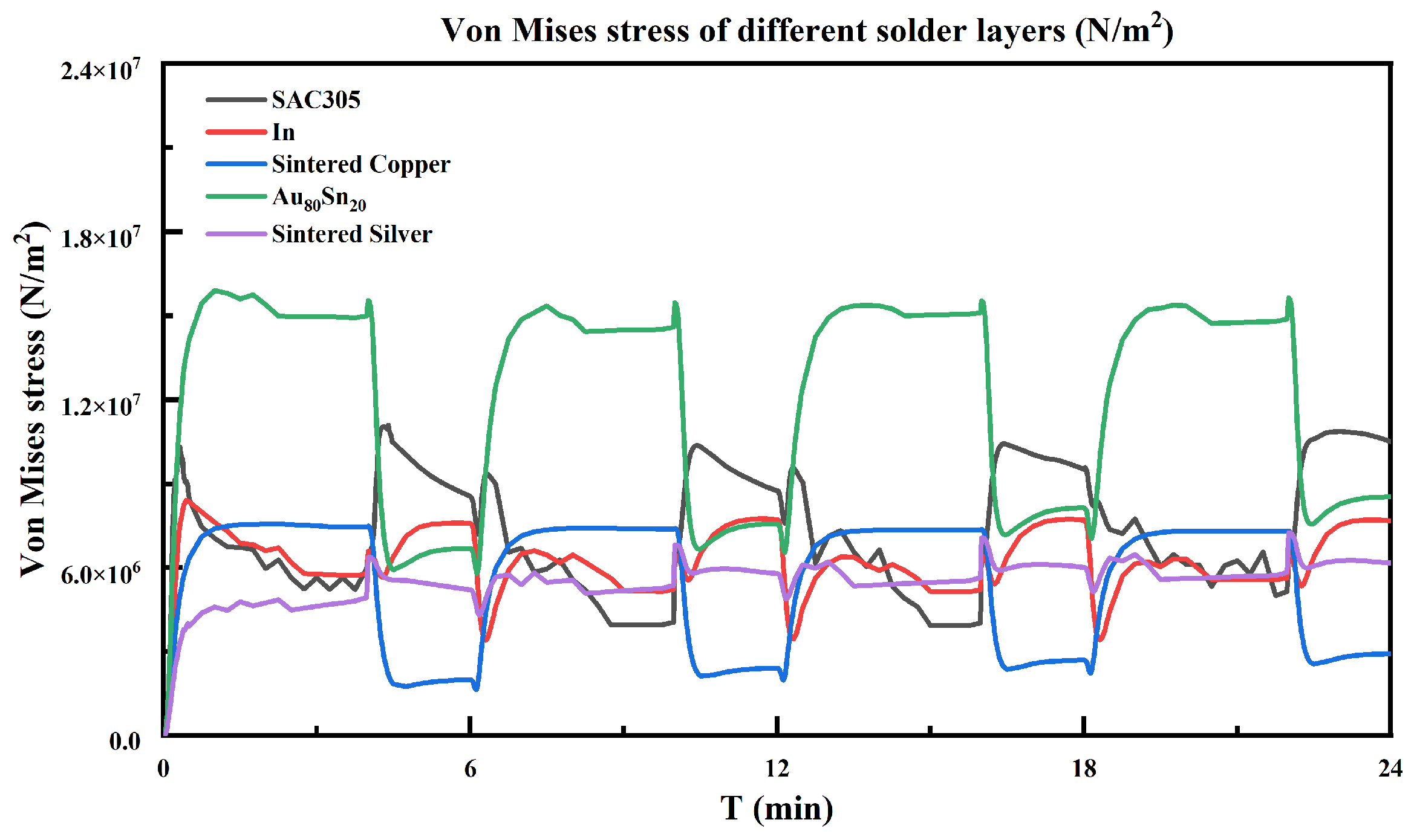
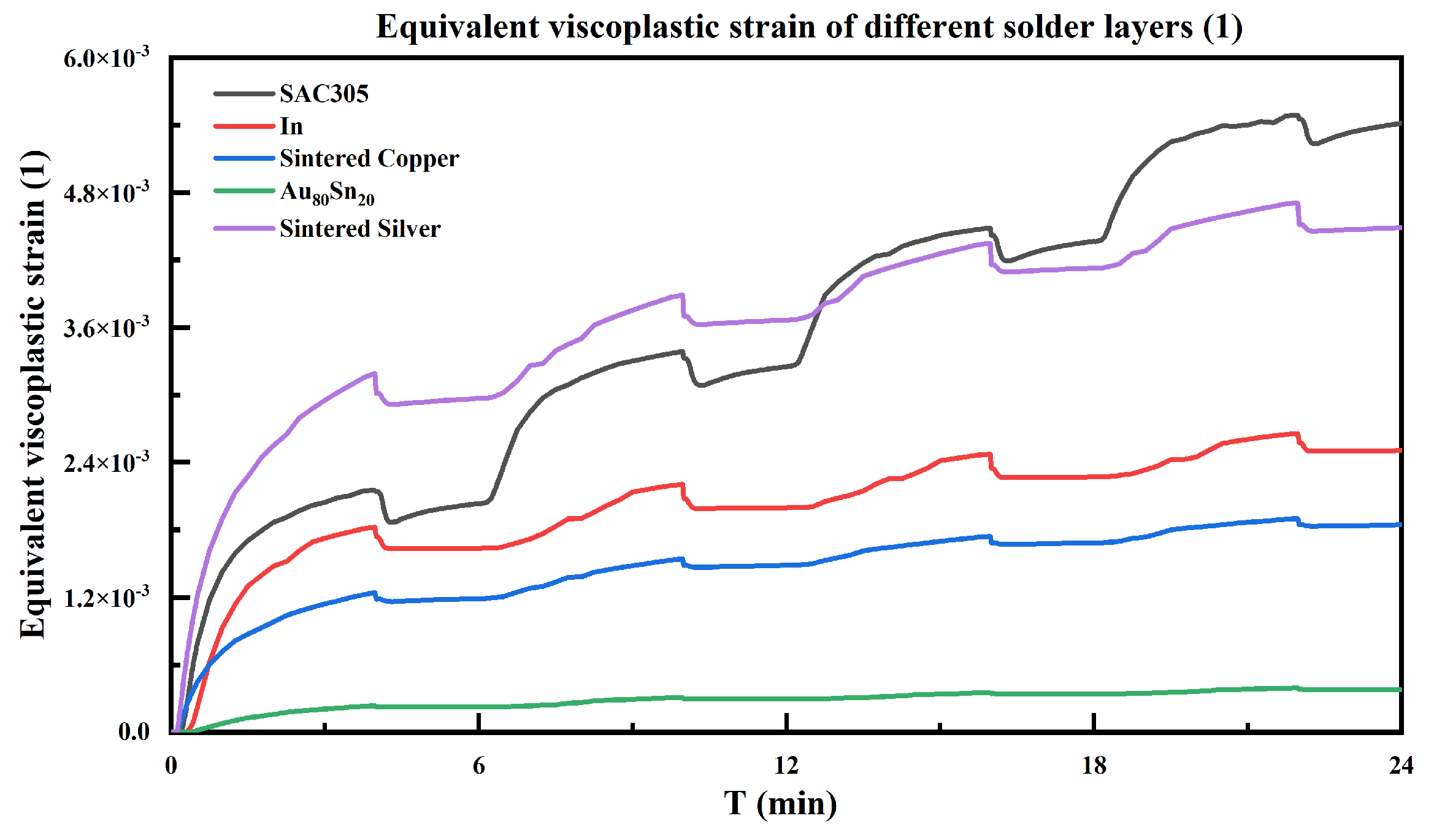
Then, this article selected positions with relatively large equivalent viscoplastic strains (Figure 7c) to compare the changes in stress–strain over time for five types of solder materials. Figure 8 shows that the stress peak of Au80Sn20 is the highest, and the stress peak of sintered silver is the lowest. The stress fluctuations of various solder materials over time correspond to the power cycle curve, showing four cycles, and the fluctuation of each cycle is similar. This situation can also be seen in Figure 9, where the viscoplastic strain also shows a trend of four cycles. However, the viscoplastic strain gradually accumulates and increases, which cannot be recovered. In addition, it can be seen that the five types of solder materials with varying degrees of viscoplastic strain are SAC305, sintered silver, indium, sintered copper, and gold tin alloy. Based on this, it can be preliminarily judged that gold tin alloy has the best reliability, while SAC305 solder material has the worst reliability.
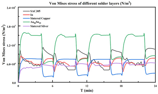
Figure 8.
Stress variation at the same failure point of different solders under power cycle load.
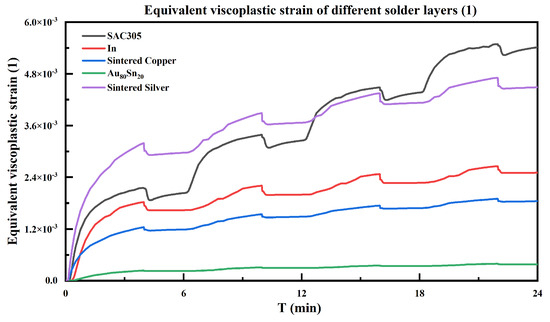
Figure 9.
Equivalent viscoplastic strain change of different solders at the same failure point under power cycle load.
3.3. Electro-Thermal Coupling Complex Reliability Analysis
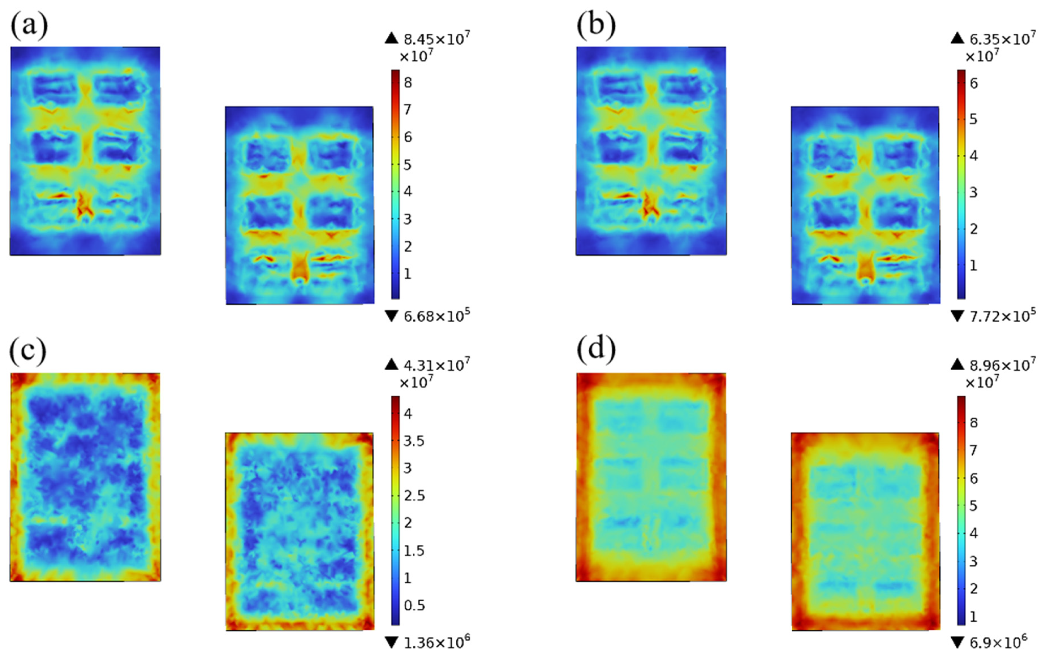
Electrothermal coupling complex reliability requires that the test power be turned on or off under specified high and low-temperature conditions. Therefore, the power curve and ambient temperature greatly affect the reliability of the IGBT module. Taking SAC305 solder as an example, Figure 9 presents the stress distribution of the solder layer in four different states. By comparing Figure 10a,b we can conclude that the stress concentration location of IGBT turn-on and turn-off is basically the same in the high-temperature environment, and the difference is only the size of the stress value. This can indicate that the ambient temperature has a greater impact on the reliability of the IGBT module than the power. The comparison of Figure 10c,d also leads to the consistent conclusion that at, low temperatures, the maximum stress is always concentrated at the edge of the solder layer, regardless of whether the IGBT module is turned on or off.

Figure 10.
Stress distribution in the solder layer at four states: (a) highest ambient temperature at 8 min, IGBT on, (b) highest ambient temperature at 11 min, IGBT off, (c) lowest ambient temperature at 31 min, IGBT on, (d) lowest ambient temperature at 29 min, IGBT off.
In addition, the viscoplastic strains were calculated based on the Anand viscoplastic model as shown in Figure 11. In comparison with Figure 7c, it can be concluded that the viscoplastic strain distribution is nearly the same in the electro-thermal coupling complex case and under power cycling; however, the viscoplastic strain values are very different. This indicates that, on top of the power cycling, the alternating changes in the external environment further accelerate the lifetime of the solder layer of the IGBT module.
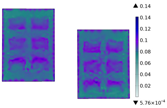
Figure 11.
Equivalent viscoplastic strain of solder layer SAC305.
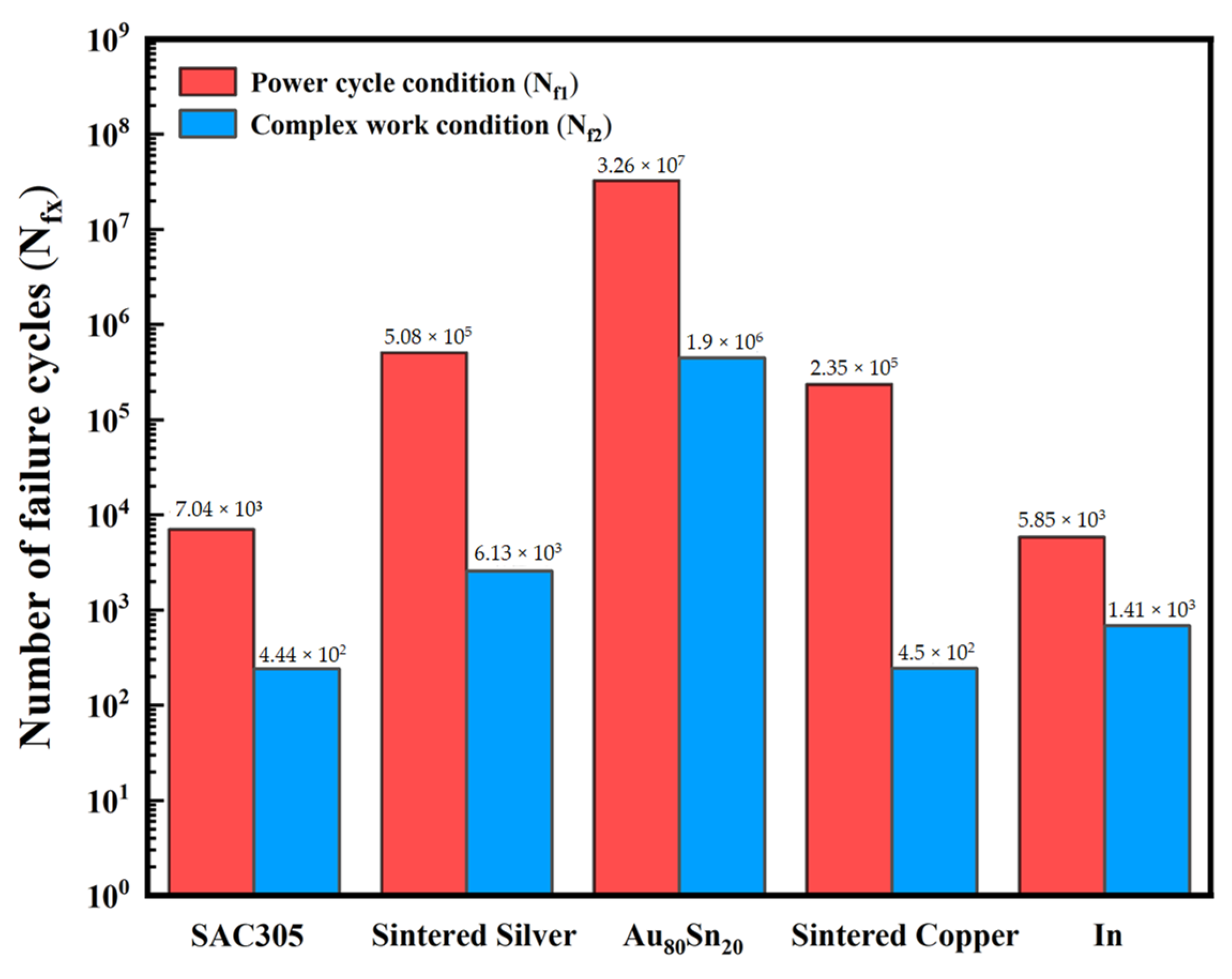
Finally, based on the C-M model, the minimum lifespan of each solder layer was calculated according to the viscoplastic strain. Figure 12 compares the lifespan under two reliability testing conditions. It can be seen that regardless of the power cycle reliability testing or the complex working state, the lifespan of the Au80Sn20 solder is the highest, reaching 3.26 × 10⁷ cycles and 1.9 × 10⁶ cycles, respectively, indicating the best reliability. The lifespan of sintered silver is second, and its reliability is relatively good. SAC305 and indium have the worst reliability, with only 7.04 × 10³ and 5.85 × 10³ cycles, respectively, in power cycle testing. They have fewer failure cycles in complex working environments, which is four orders of magnitude worse than Au80Sn20. Peng Bo et al. [31] calculated and compared the reliability and life of three different types of interconnect interface materials (In, Au80Sn20 and nano silver solder paste) of high-power semiconductor lasers under thermal shock conditions of −55 °C~125 °C. The results show that the typical soft solder In has the highest strain energy density accumulation and the lowest life under the thermal shock condition. Hard solders represent the Au80Sn20 with the highest reliability and longest life. In addition, the new interconnect interface material nano-silver solder paste shows good thermal shock deformation resistance and long effective life, which has high application potential value. This is highly consistent with the conclusion of this paper.

Figure 12.
Fatigue life of the five solders under two test conditions.
4. Conclusions
This article conducts finite element simulation on the DC operation of an IGBT half-bridge module and preliminarily compares the junction temperature of IGBT under five different solder conditions. Using the Anand constitutive model and Coffin–Manson lifetime model, the lifetimes of five types of solder materials under two different reliability tests were calculated, and the following three conclusions were drawn:
- The thermal reliability of the silver sintered material is particularly impressive, as the application of the solder material significantly reduces the DC operating junction temperature of the IGBT module to only 90.2 °C. This temperature represents a significant advantage of almost 15 °C compared to the IGBT module using SAC305 solder. This advantage not only improves the module’s thermal management efficiency but also significantly increases its long-term stability and reliability. Lower junction temperatures help to extend the life of the device and reduce the risk of potential failure due to overheating, thus improving the reliability performance of IGBT modules in real-world applications.
- In the studies conducted for power cycle reliability testing, significant differences in the fatigue life of different solder materials were observed. Specifically, the Au80Sn20 alloy solder showed superior fatigue performance with a fatigue life of up to 3.26 × 10⁷ cycles. This value not only reflects the stability and durability of the material under long-term cyclic loading, but also indicates its potential for application in high-temperature, high-stress environments. In contrast, the fatigue life of indium solder is shorter at 5.85 × 10³ cycles, a difference of almost four orders of magnitude, highlighting the significant impact of metallic solder on fatigue behavior.
- In the complex electro-thermal coupling environment, the Au80Sn20 solder also shows the best fatigue life of 1.9 × 10⁶ cycles, indicating its good adaptability and reliability under extreme working conditions. On the contrary, SAC305 solder shows a fatigue life of only 4.44 × 10² cycles in this environment, demonstrating its disadvantage under high thermal loads. This finding emphasizes that when designing IGBT modules, the selection of solder materials needs to fully consider their thermal performance and reliability in different operating environments to ensure the long-term stable operation of the products.
In summary, the results of this study not only reveal the significant differences in thermal management and reliability of IGBT modules with different welding materials but also provide important theoretical support and practical reference for further optimizing the design and application of IGBT modules. Future research can be centered on the improvement of welding materials and their impact on the performance of IGBT modules for more in-depth exploration in order to promote the continuous development and application of electronic power devices.
Author Contributions
Conceptualization, M.G. and H.M.; methodology, M.G.; software, M.G.; validation, M.G., H.M., and X.T.; formal analysis, M.G.; investigation, W.T.; resources, M.G.; data curation, M.G.; writing—original draft preparation, M.G.; writing—review and editing, M.G.; visualization, M.G.; supervision, H.M.; project administration, H.L.; funding acquisition, H.L. All authors have read and agreed to the published version of the manuscript.
Funding
This work was supported by the National Natural Science Foundation of China (Grant No. 52101035).
Data Availability Statement
The data presented in this study are available on request from the corresponding author.
Conflicts of Interest
The authors declare no conflicts of interest.
References
- Yang, Y.J. Research on Dynamic Simulation and Adaptive Design of Space Computer. Ph.D. Thesis, Xidian University, Xi’an, China, 2009. [Google Scholar]
- Zhang, K.; Liu, Y.; Kwok, H.-S.; Liu, Z. Investigation of electrical properties and reliability of GaN-based micro-LEDs. Nanomaterials 2020, 10, 689. [Google Scholar] [CrossRef] [PubMed]
- Coffin, L.F., Jr. A study of the effects of cyclic thermal stresses on a ductile metal. Trans. Am. Soc. Mech. Eng. 1954, 76, 931–949. [Google Scholar] [CrossRef]
- Manson, S.S. Behavior of Materials under Conditions of Thermal Stress; National Advisory Committee for Aeronautics: Washington, DC, USA, 1953; Volume 2933.
- Engelmaier, W. Fatigue life of leadless chip carrier solder joints during power cycling. IEEE Trans. Compon. Hybrids Manuf. Technol. 1983, 6, 232–237. [Google Scholar] [CrossRef]
- Solomon, H.D. The influence of hold time and fatigue cycle wave shape on the-low cycle fatigue of 60/40 solder. In Proceedings of the 38th Electronics Components Conference, Los Angeles, CA, USA, 9–11 May 1988; Proceedings. pp. 7–12. [Google Scholar]
- Yang, H. Influencing factors of fatigue life of nano-silver paste in chip interconnection. J. Electron. Mater. 2021, 50, 224–232. [Google Scholar] [CrossRef]
- Yang, K.; Zhou, L.; Wu, F.; Zhang, Y.; Han, Y.; Zhang, Z.; Wan, Y.; Huang, X.; Huang, D. Evaluation of Fatigue Crack Growth in Solder Layer of IGBT Module under Power Cycle by Using J-integral Method. In Proceedings of the 2021 22nd International Conference on Electronic Packaging Technology (ICEPT), Xiamen, China, 14–17 September 2021; pp. 1–6. [Google Scholar]
- Wakamoto, K.; Namazu, T. Mechanical Characterization of Sintered Silver Materials for Power Device Packaging: A Review. Energies 2024, 17, 4105. [Google Scholar] [CrossRef]
- Zhang, G.; Feng, S.; Zhou, Z.; Liu, J.; Li, J.; Zhu, H. Thermal fatigue characteristics of die attach materials for packaged high-brightness LEDs. IEEE Trans. Compon. Packag. Manuf. Technol. 2012, 2, 1346–1350. [Google Scholar] [CrossRef]
- Wang, Y.; Xu, D.; Yan, H.; Li, C.-F.; Chen, C.; Li, W. Low-temperature Copper Sinter-joining Technology for Power Electronics Packaging: A Review. J. Mater. Process. Technol. 2024, 332, 118526. [Google Scholar] [CrossRef]
- Ni, Y.; Chen, D.Y.; Cai, M.; Yang, D.G. Thermal mechanical analysis and fatigue life prediction of nano silver sintered layer encapsulated in SiC chip. Electron. Compon. Mater. 2024, 43, 238–245. [Google Scholar]
- Chen, W.; Yan, X.; Ibrahim, M.S.; Meda, A.H.; Fan, X.; Zhang, G.; Fan, J. Thermal-mechanical-electrical Co-design of Fan-Out Panel-Level SiC MOSFET Packaging with a Multi-objective Optimization Algorithm. In Proceedings of the 2023 IEEE 73rd Electronic Components and Technology Conference (ECTC), Orlando, FL, USA, 30 May–2 June 2023; pp. 2007–2011. [Google Scholar]
- Huang, X.; Wang, Y.; Zhu, Q.; Du, Z.; Zhou, L.; Liu, H. Thermal creep and fatigue failure of the sintered silver solder in a SiC-IGBT module under power cycling. Eng. Fail. Anal. 2023, 154, 107625. [Google Scholar] [CrossRef]
- Zhang, G.S. Study on Mechanical Properties of 80Au/20Sn Filler Metal Alloy. Ph.D. Thesis, Tianjin University, Tianjin, China, 2010. [Google Scholar]
- Long, H.Y. Electrothermally-Force-Multiple Physical Field Modeling and Failure Analysis of IGBT Devices Packaged by Nano Silver Sintering and Pressing. M.S. Thesis, Chongqing University, Chongqing, China, 2020. [Google Scholar]
- Wu, R.; McCluskey, F.P. Reliability of indium solder for cold temperature packaging. In Proceedings of the ASME InterPACK Conference, Vancouver, BC, Canada, 8–12 July 2007; pp. 553–556. [Google Scholar]
- Calabretta, M.; Sitta, A.; Oliveri, S.M.; Sequenzia, G. Power semiconductor devices and packages: Solder mechanical characterization and lifetime prediction. IEEE Access 2021, 9, 22859–22867. [Google Scholar] [CrossRef]
- Long, X.; Liu, Y.; Jia, F.; Wu, Y.; Fu, Y.; Zhou, C. Thermal fatigue life of Sn–3.0 Ag–0.5 Cu solder joint under temperature cycling coupled with electric current. J. Mater. Sci. Mater. Electron. 2019, 30, 7654–7664. [Google Scholar] [CrossRef]
- Smet, V.; Forest, F.; Huselstein, J.-J.; Richardeau, F.; Khatir, Z.; Lefebvre, S.; Berkani, M. Ageing and failure modes of IGBT modules in high-temperature power cycling. IEEE Trans. Ind. Electron. 2011, 58, 4931–4941. [Google Scholar] [CrossRef]
- Tang, Y.; Wang, B.; Chen, M.; Liu, B.L. Reliability and online evaluation of IGBTs at high temperatures. Trans. China Electrotech. Soc. 2014, 29, 17–23. [Google Scholar]
- Deng, E.P.; Chen, J.; Zhao, Y.S.; Zhao, Z.B.; Huang, Y.Z. Development of 90kW/3000A high voltage and high power IGBT device power cycle test equipment. Semicond. Technol. 2019, 44, 223–231. [Google Scholar]
- Li, Y.P.; Zhou, L.W.; Sun, P.J. Summary of accelerated aging methods for IGBT power modules. J. Power Supplies 2016, 14, 122–135. [Google Scholar]
- Hensler, A.; Lutz, J.; Thoben, M.; Zachariae, J. Power cycling tests at high temperatures with IGBT power modules for hybrid electrical vehicle applications. In Proceedings of the 3rd Electronics System Integration Technology Conference ESTC, Berlin, Germany, 13–16 September 2010; pp. 1–6. [Google Scholar]
- Huang, H.; Mawby, P.A. A lifetime estimation technique for voltage source inverters. IEEE Trans. Power Electron. 2012, 28, 4113–4119. [Google Scholar] [CrossRef]
- Smet, V.; Forest, F.; Huselstein, J.-J.; Rashed, A.; Richardeau, F. Evaluation of Vce Monitoring as a Real-Time Method to Estimate Aging of Bond Wire-IGBT Modules Stressed by Power Cycling. IEEE Trans. Ind. Electron. 2012, 60, 2760–2770. [Google Scholar] [CrossRef]
- Guo, Y.Q.; Gao, T.; Xu, Y.J.; Liang, L.H.; Liu, Y. Life prediction of power module lead bond interface temperature cycle. J. Mech. Electr. Eng. 2018, 35, 73–78. [Google Scholar]
- Ji, B.; Song, X.; Cao, W.; Pickert, V.; Hu, Y.; Mackersie, J.W.; Pierce, G. In situ diagnostics and prognostics of solder fatigue in IGBT modules for electric vehicle drives. IEEE Trans. Power Electron. 2014, 30, 1535–1543. [Google Scholar]
- Ciappa, M. Selected failure mechanisms of modern power modules. Microelectron. Reliab. 2002, 42, 653–667. [Google Scholar] [CrossRef]
- Huang, Y.; Luo, Y.; Xiao, F.; Liu, B. Failure mechanism of die-attach solder joints in IGBT modules under pulse high-current power cycling. IEEE J. Emerg. Sel. Top. Power Electron. 2018, 7, 99–107. [Google Scholar] [CrossRef]
- Peng, B.; Zhang, P.; Chen, T.Q.; Zhao, R.C.; Wu, Z.H.; Liu, H. Reliability study of interconnect interface for high-power semiconductor lasers. Infrared Laser Eng. 2018, 47, 109–116. [Google Scholar]

Disclaimer/Publisher’s Note: The statements, opinions and data contained in all publications are solely those of the individual author(s) and contributor(s) and not of MDPI and/or the editor(s). MDPI and/or the editor(s) disclaim responsibility for any injury to people or property resulting from any ideas, methods, instructions or products referred to in the content. |
© 2024 by the authors. Licensee MDPI, Basel, Switzerland. This article is an open access article distributed under the terms and conditions of the Creative Commons Attribution (CC BY) license (https://creativecommons.org/licenses/by/4.0/).