Article

Microstructure and Properties of Gradient Ti(C,N)-Based Cermets by Powder Extrusion Additive Manufacturing

1
College of Materials and Advanced Manufacturing, Hunan University of Technology, Zhuzhou 412007, China
2
Jiangsu Co-Innovation Center of Efficient Processing and Utilization of Forest Resources, International Innovation Center for Forest Chemicals and Materials, College of Materials Science and Engineering, Nanjing Forestry University, Nanjing 210037, China
*
Authors to whom correspondence should be addressed.
Metals 2024, 14(10), 1161; https://doi.org/10.3390/met14101161
Submission received: 30 August 2024 / Revised: 6 October 2024 / Accepted: 10 October 2024 / Published: 11 October 2024

Abstract

:
Ti(C,N)-based cermets are crucial for high-speed cutting tools and other high-temperature applications, yet there remains a considerable gap in their preparation controllability, fracture strength, and toughness compared to cemented carbide. Despite numerous studies having focused on modifying the hardness and toughness of Ti(C,N)-based cermets by varying process parameters and chemical compositions, this research has used gradient Ti(C,N)-based cermets produced by powder extrusion additive manufacturing (PEM) technology, which is rare. This study developed the gradient structure layer by layer using PEM. The microstructure of the printed and sintered parts was studied, and the hardness, fracture toughness, and bending strength of the gradient material were analyzed. The gradient material demonstrates superior mechanical properties compared to traditional Ti(C,N)-based cermets, with a hardness of 1760 23 + 39 HV20, a fracture toughness of 8.5 0.4 + 0.3 MPa·m1/2, and a bending strength of 2047 43 + 22 MPa. The research will assist researchers in assessing the potential application of PEM and broaden the application fields of gradient Ti(C,N)-based cermets.

1. Introduction

High-speed cutting technology serves as the foundation and core for efficient machining in the fields of aerospace, transportation, and others [1,2,3]. The conditions of high-speed cutting are severe, and domestic high-speed precision cutting of difficult-to-process materials still greatly relies on imported tools. Ti(C,N)-based cermets have significant potential in extremely severe service environments due to their excellent red hardness, wear resistance, and chemical stability [4,5,6,7,8].
Currently, homogeneous or coated structures are generally used for Ti(C,N)-based cutting tools [9]. The homogeneous structure presents an inherent contradiction between hardness and toughness, while the coated structure carries the risk of coating spalling and substrate deformation failure, severely limiting its service life and widespread application [10,11]. In recent years, researchers have improved the mechanical properties of Ti(C,N)-based cermets to some extent by adjusting composition [12,13,14,15], optimizing the volume content [16,17,18], implementing new technologies [19,20,21,22], etc. However, these methods struggle to balance hardness with strength and toughness.
Gradient materials exhibit unique mechanical response behaviors under external loads, characterized by thermal relaxation and dispersion, which can regulate internal stress distribution and achieve material toughening. This provides a novel approach for the development of new tool structures. Zhao et al. [23] conducted nitriding treatment during the cooling process post-sintering to form a 200 μm metal-poor phase gradient functional area on the surface of Ti(C,N)-based cermets. This method avoids traditional coating spalling issues but does not address the brittleness of Ti(C,N)-based cermets. Ji et al. [24] prepared a three-layer gradient Ti(C,N)-based cermet tool based on the redistribution of the metal phase driven by elemental diffusion. Zheng et al. [23] designed and synthesized a macrogradient structure which originated from the denitrification-induced W solubility change in Ti(C,N). However, these methods are highly sensitive to process variations and difficult to control.
Ti(C,N)-based cermets are primarily produced using traditional powder metallurgy techniques, such as isostatic pressing or molding [25,26,27]. These methods are constrained by mold shape and size, and it is challenging to process and form in one step. Additionally, post-machining of Ti(C,N)-based cermets is extremely difficult due to their high hardness and brittleness [28,29]. Additive manufacturing (AM) technology has developed over the past few decades, and this process has realized the synchronization of research, design, and manufacturing [30]. AM technology has been applied to the aerospace, medical, automotive, and engineering industries due to its many advantages, such as the complexity of the parts it can create, short fabrication time, and repeatability. Powder extrusion additive manufacturing (PEM) is an indirect printing technology that relies on its extensive design freedom and cost-effectiveness over traditional AM technologies such as selective laser melting based on high-energy beams [31,32]. PEM takes place at low temperatures and printing does not involve melting of metal and ceramic powders, allowing for precise control of the gradient layer’s thickness, composition, and uniformity. It overcomes the limitations of traditional powder metallurgy regarding product shape, size, and gradient distribution, and the gradient structure enables a rational material stress distribution.
Yi et al. [33] introduced a high-flow filling approach based on the effective control of viscosity during deposition and confirmed potential applications of PEM in cutting tools. Aramian et al. [34] reviewed additive manufacturing of cermets and indicated that the deposition behavior mainly depended on the rheological properties of the feedstocks and printing parameters. Naveen Kumar et al. [35] reviewed extrusion-based 3D printing and showed that there has been little research on the preparation of gradient Ti(C,N)-based cermets by 3D printing. This study presents the process parameters of gradient Ti(C,N)-based cermets, compares and analyzes their microstructure, and investigates properties such as density, hardness, bending strength, and failure behavior.

2. Experimental Procedure

2.1. Materials and Process

The printing mixtures are composed of a blend of metal ceramic powder and 8 wt.% thermoplastic polymers. The gradient Ti(C,N)-based cermets in this study consist of three layers of composition distribution from the outside to the inside. The nominal composition distribution is shown in Table 1. The polymers primarily consist of 35 wt.% PW and 65 wt.% water-soluble PEG.
Three types of homogeneous powder mixtures added with PW were prepared by ball milling for 24 h at the rotation speed of 200 r/min, and the ball-to-material ratio was 6:1. Subsequently, PEG was added into the mixtures and mixed on a mixer at 135 °C with a rate of 30 r/min for one hour. The mixed feedstocks were then crushed into particles with a size around 3 mm. During the PEM process, firstly, a 3D CAD model was built, then the feedstocks were heated and extruded by a screw, and the gradient Ti(C,N)-based green part was built layer by layer. After extrusion printing, the binder was removed through a process known as debinding, which includes solvent debinding and thermal debinding. Different debinding temperatures (50 °C, 60 °C) and debinding times (50 h, 72 h, and 90 h) were adopted in solvent debinding. Consequently, the brown parts were sintered to form dense gradient Ti(C,N)-based cermets. The simplified process flowchart of the PEM process can be seen in Figure 1, with detailed processing parameters discussed later.

2.2. Characterizations

The surface and fracture morphology were examined using a scanning electron microscope (Clara, Tescan, Czech Republic). Specimen density was determined by the Archimedes method. The hardness and fracture toughness of polished specimens were measured using the Vickers indentation technique with a load of 20 kg. The Vickers hardness was calculated by the following equation:
HV = 1.8544 P d 2
where HV is Vickers hardness [MPa], P is the load [196 N], and d is the average diagonal length of indentation [mm]. Fracture toughness was estimated according to the following equation:
K IC   = 0.203   ×   ( 2 c d ) 3 2   ·   ( d 2 ) 1 2 · HV
where KIC is fracture toughness [MPa.m1/2], and c is average diagonal crack length [mm].
Bending strength testing was conducted using an Instron3369-type mechanical testing machine with a span of 20 mm at a loading speed of 0.5 mm/min based on GB/T 6569-2006 [36]. The standard bending bars with dimensions of 5.25 × 6.5 × 20 mm were tested. All specimens for performance testing were obtained under the same process parameters, and the results were calculated based on three measurements.

3. Results and Discussion

3.1. Characterization of the Printed Parts

Considering the polymer in the feedstocks, it is assumed that the contraction is uniform and all directions would be shrunk by 16%. Consequently, rectangular green parts with dimensions of 5.25 × 6.5 × 20 mm (1#) and 6.1 × 7.6 × 23.2 mm (2#) were fabricated using a powder extrusion 3D printer. Different feedstocks were deposited at designated positions through various nozzles at 165 °C, building the complex gradient structure layer by layer with a layer height of 200 μm and a printing direction of 45°. After deposition, the deposited layer rapidly cooled from the melting temperature to solidify, and when new feedstocks were deposited on the previously solidified layer, a non-uniform temperature gradient was produced. This caused shrinkage of the green part and resulted in residual stress, and this stress led to deformation of the printed part. Consequently, the printed specimens were cured at 80 °C for 2 h in a drying cabinet, likely functioning as an annealing treatment to slowly release internal stress and enhance green strength.
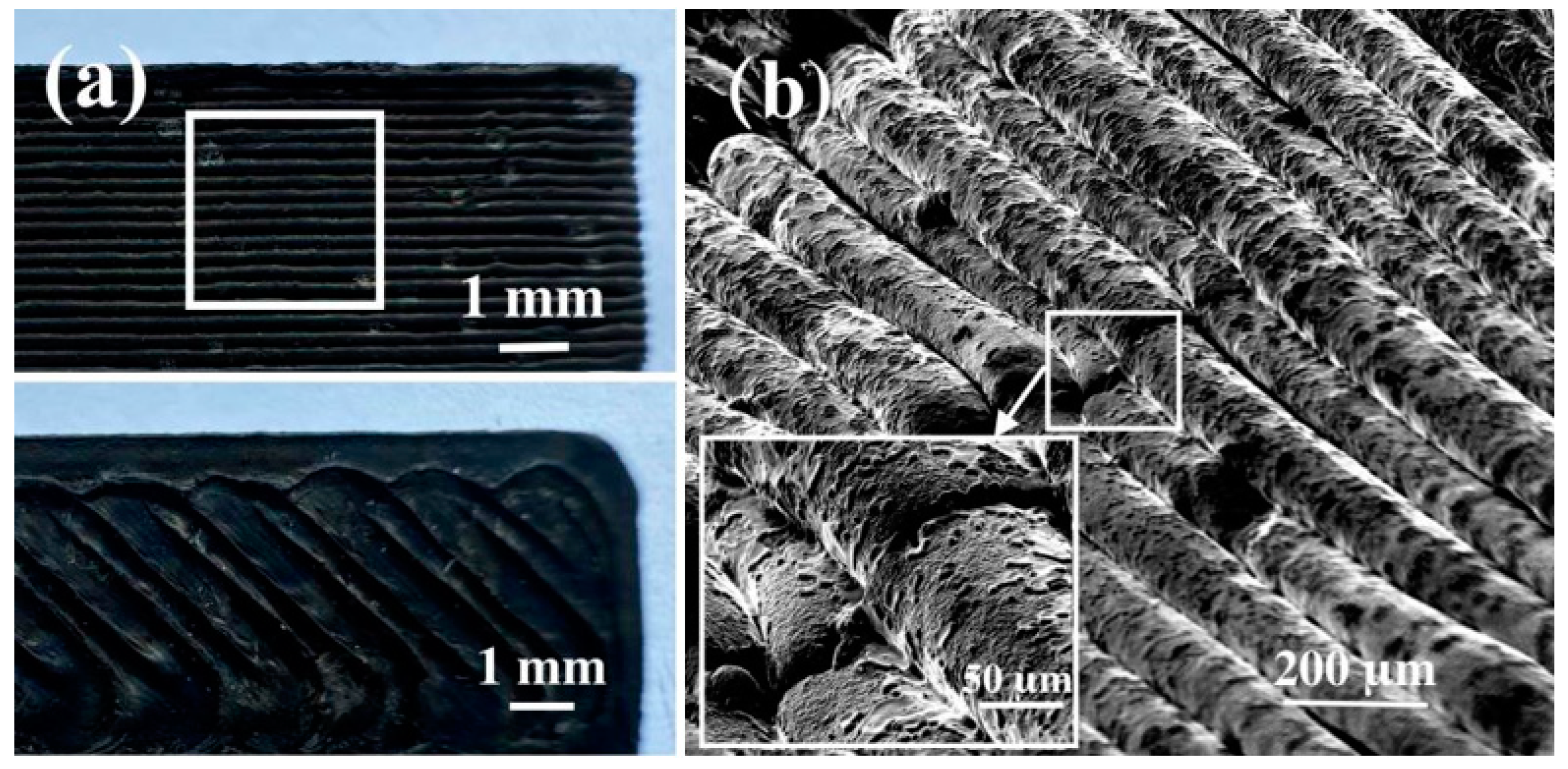
SEM is effective to investigate the surfaces of materials [37,38,39,40,41].The morphology of the printed specimens is shown in Figure 2. It can be concluded that defect-free green parts can be printed under the current printing parameters. The steps and gaps due to layer-by-layer deposition cause surface roughness, but they only exist in the surface layers and do not affect the adhesion between internal layers. The gradient orientation is parallel to the building direction, and the printed parts achieve high green density through proper interlayer bonding without long chains of voids caused by improper process parameters. The enlarged SEM image of the marked zone in Figure 2a is shown in Figure 2b, where the screw-based system increases extrusion force and dimensional stability. Due to the suitable pressure required for extrusion and the appropriate rheology of the feedstocks, each layer is straight, uniform, and continuous. The gap between layers is filled with dissolved polymer, resulting in a smoother surface and increased bond strength to previously printed layers. As a result, extrusion and print voids are not visible in the microstructure.

3.2. Effect of Solvent Debinding Parameters on the Printed Parts

To determine the optimal debinding process, the effects of different specimen sizes, debinding temperatures, and debinding times on the debinding rate were studied. Two types of specimens with dimensions of 5.25 × 6.5 × 20 mm (1#) and 6.1 × 7.6 × 23.2 mm (2#) were used, with distilled water as the solvent, immersed at 50 and 60 °C for 50, 72, and 90 h, respectively. The results are shown in Figure 3. It can be seen that specimen size significantly affects the speed of polymer removal. In addition, the debinding temperature and time must be carefully controlled.
Since solvent debinding is driven from the outside to the inside of the green part, some dissolved polymer components need to diffuse from the open channel to the specimen surface and are removed in the distilled water. An increase in specimen size increases the diffusion path, reducing the solvent debinding rate. Additionally, the water-soluble polymer system reduces the use of hazardous solvents during debinding, making it safer and more cost-effective for practical applications.
It also can be observed that more water-soluble polymer is removed when the period of debinding time is extended. In the early stage of debinding, the solvent and the water-soluble polymer are in direct contact, so the debinding rate is higher. After the binder is dissolved, it needs to diffuse to the surface of the printed part. With the extension of debinding time, the concentration difference between the inside and outside of the part gradually decreases. A dynamic equilibrium between polymer and solvent is attained, resulting in a significant decrease in the debinding rate.
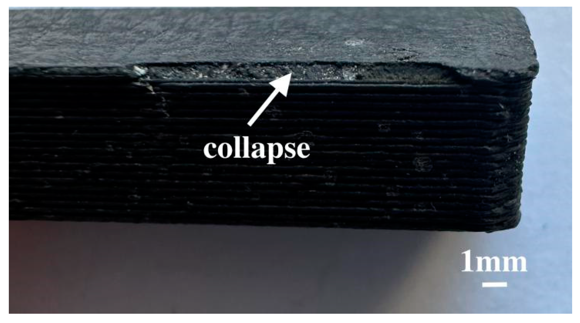
As the immersion temperature increases from 50 °C to 60 °C, the residual polymer content decreases significantly due to faster diffusion. However, when it is held at 60 °C for 90 h, the long debinding time at a high temperature softens the residual polymer, and the forces generated during polymer removal, such as capillary forces during polymer dissolution in the solvent, exceed the bonding force between powder particles. This causes the green part to lose its shape and collapse; its surface morphology is shown in Figure 4. Moreover, when the temperature is too low, the diffusion rate of the water-soluble components decreases, and the swelling effect of the solvent in the residual polymer cannot be compensated for by the removal of water-soluble components, significantly reducing debinding efficiency.
A longer debinding time produces a higher removal rate. However, as the concentration of the water-soluble agent in the distilled water increases, the concentration difference between the water-soluble components and the distilled water decreases, reducing the dissolution and diffusion rate of the water-soluble components and deteriorating the debinding rate. Therefore, the solvent debinding process is most effective in constant-temperature distilled water at 60 °C for 50 h, with up to 63 wt.% and 53 wt.% of the polymer successfully eliminated. It was found that the polymer could be quickly dissolved without causing flaws in the green part.

3.3. Microstructure and Properties of Gradient Ti(C,N)-Based Cermet

Solvent debinding only removes water-soluble components, so the remaining polymer must be completely removed before sintering otherwise the carbon content will decompose due to the remaining polymer at the sintering temperature, forming free carbon, which can result in poor properties in Ti(C,N)-based cermets. Since the PW decomposed violently between 250 °C and 450 °C, the cured parts were thermally debinded at 360 °C and 420 °C for 150 min each, followed by sintering at 1430 °C and 1500 °C for 1.5 h, respectively. The brown parts were sintered to achieve a high sintered density up to 97.13% of the theoretical full density at the temperature of 1500 °C. It is evident that the high shrinkage is mainly attributed to polymer removal and part densification. Figure 5 details the dimensional changes in various directions; it shows that the layer direction significantly affects linear shrinkage. The highest linear shrinkage up to 15.7% occurs along the layer direction, which can be attributed to the directionality of the screw pressure and the nozzle in extrusion. The polymer chains orientate, causing denser packing in the x-axis and y-axis direction. The bonding strength of the interlayer also affects the anisotropic shrinkage. In addition, due to the melting of the metal binder phase, the hard-phase particles are more significantly rearranged in the z-axis direction under the action of self-weight during the sintering process.
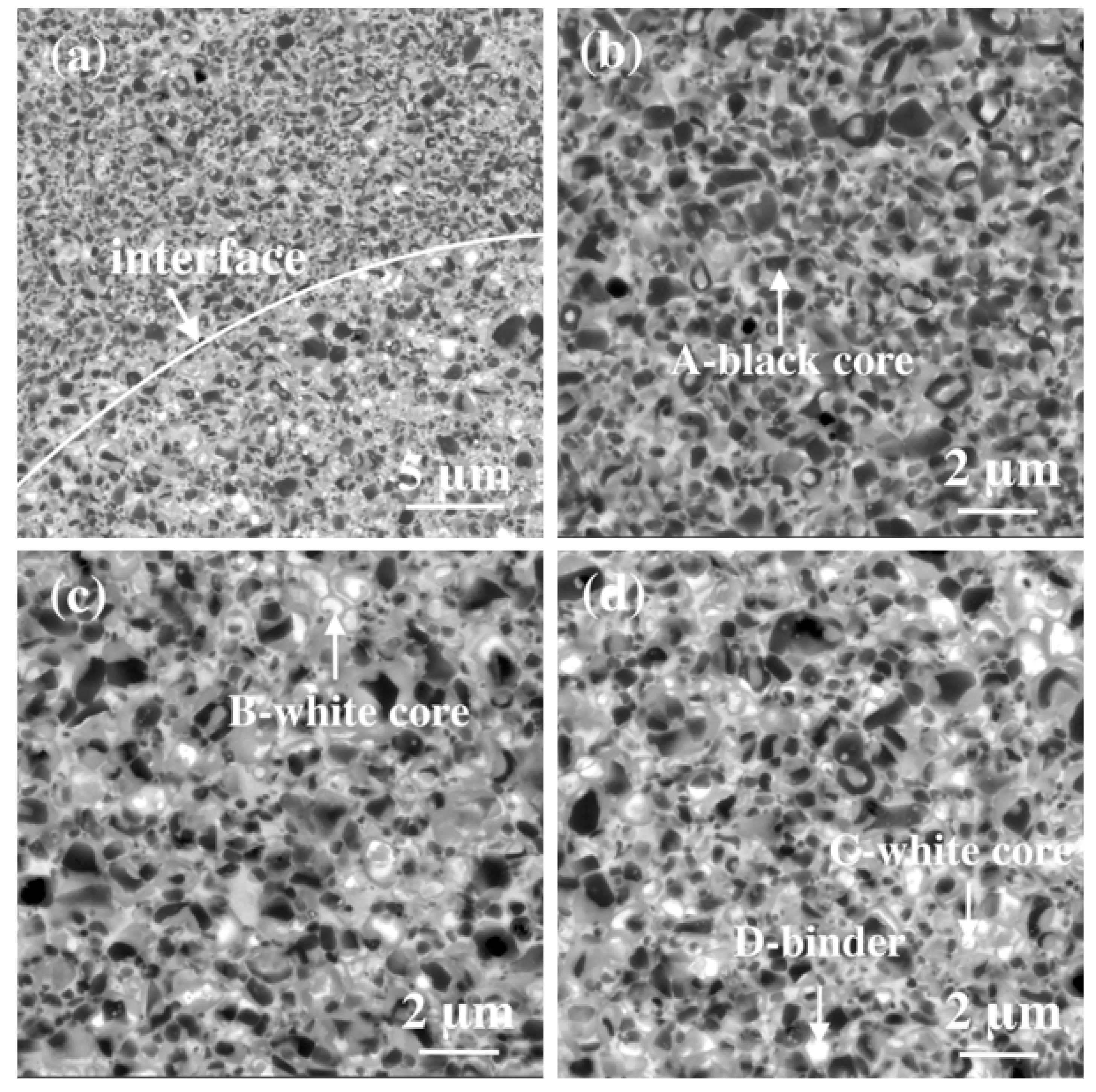
The microstructures of the sintered Ti(C,N)-based cermet obtained at different parameters are shown in Figure 6 and Figure 7, respectively. The solubility of carbides in the binder phase depends not only on the nature of heavy metal elements; temperature is also an important factor. It can be seen from Figure 6a that there is an obvious interface between the gradient layers, and incomplete diffusion migration to produce a non-uniform microstructure in the cermet. The different content of binder phase leads to significant changes in the microstructure. The undissolved original particle in layer 1 (Figure 6b) shows obvious sharp corners. The average particle size of the hard particle is 2 μm, and it is is surrounded by the metal binder phase and does not have a rim phase. The tendency of carbide dissolution increases as the content of the binder phase increases to 28% (Figure 6c), and particles without core–rim structures are predominant. The sharp corners of the hard particles are rounded, many spherical particles appear, and the particles are obviously refined. In layer 3 (Figure 6d), two main types of structures can be identified. One type has a core–rim structure in which the black core occupies most of the particles and is surrounded by a thin rim phase. In the other type, the size of the rim is larger than the core. The formation of a rim phase inhibits the coarsening of the ceramic phase, causing the particles to become even finer. However, due to the low sintering temperature, the diffusion is very slow, resulting in an insufficient distance of atomic migration, and the limited expansion of the particle contact areas leads to the formation of obvious pores in the cermet.
In the early stage of sintering, densification behavior mainly depends on particle rearrangement accompanied by plastic deformation of the metal binder phase. When the metal liquid phase is formed, the carbide phase promotes densification and the formation of a core–rim structure. The entire cross-section morphology in Figure 7a exhibits a uniformly distributed core–rim structure formed by the dissolution and precipitation of secondary carbides. It is clearly visible that the coherent and continuous interface of the gradient layer lacks common layered structural material defects such as delamination or interface cracks. It can be concluded that a higher temperature led to less porosity remaining in the sintered part.
Since the binder phase contributes more to fracture toughness than the ceramic phase, the microstructure of each layer from the outside to the inside (Figure 7b–d) shows an increasing content of Co and Ni binder phase in the gradient material, which can improve the fracture toughness of the material. Additionally, the higher ceramic phase content of layer 1 ensures the high surface hardness of the gradient material. A distinct difference can be recognized in terms of composition, with a black core–gray rim and a white core–gray rim. EDS is an analytical technique used for the elemental analysis or chemical characterization of a sample [42,43,44]. Figure 8 shows the EDS spectra of the marked areas, and the compositions are shown in Table 2. It can be concluded that the black core is the undissolved Ti(C,N) hard particle. With the increase in the content of the binder phase, the dissolution of W and Mo in the core phase is promoted, and the white core is Ti-substituted by the diffusion of some heavy W and Mo. The binder phase, rich in Co and Ni, also appears white. The gray rim surrounding the core phase is the (Ti,Mo,W) (C,N) solid solution formed by the reaction between the secondary carbides and the Ti(C,N) core. Both the gray rim and the white core are solid solutions composed of the same elements, while the white core has a higher content of W and Mo. Hence, mismatch caused by lattice constant difference is reduced in the white core–gray rim structure.
Due to the large differences in physical properties such as plastic flow behavior, elastic modulus, and thermal expansion coefficient between the ceramic phase and the Co and Ni metallic binder, there is significant residual stress at the interface. The continuous rim network shows the completely interfacial wet adhesion between the ceramic phase and the metallic binder, allowing the cermet to adapt to long-range stress in the intermediate layer and promoting lattice matching. Moreover, the rim can isolate the ceramic phase and inhibit the dissolution–precipitation mechanism, thereby refining the grain and improving the bending strength and fracture toughness of Ti(C,N)-based cermets.
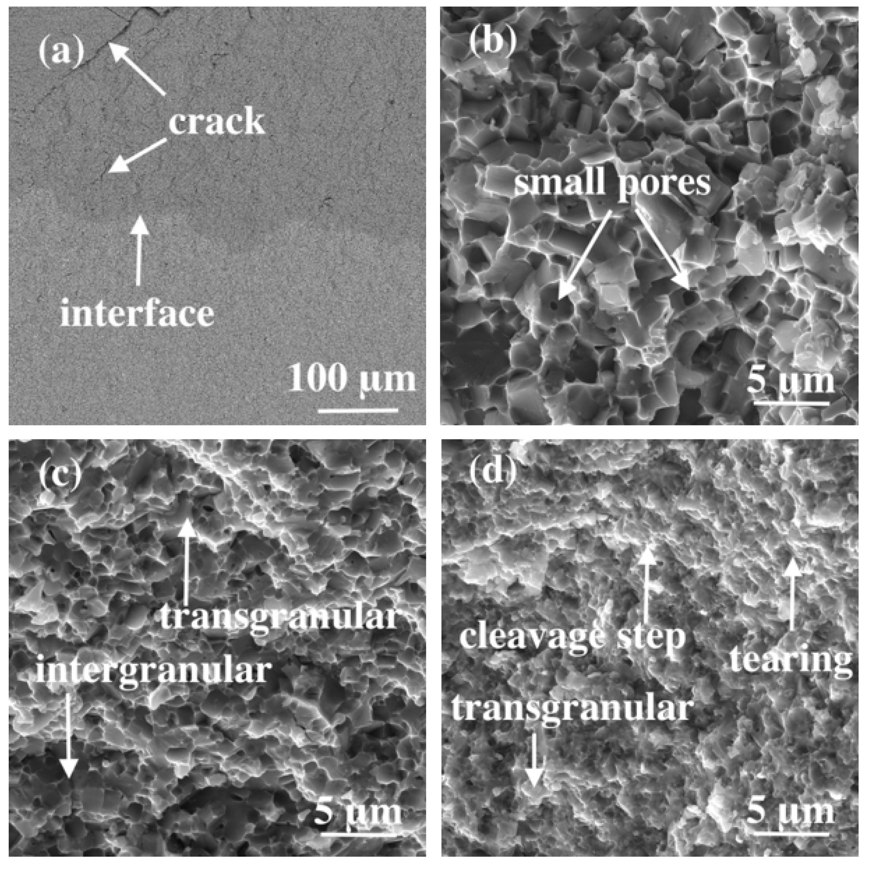
Figure 8 shows the fracture surface morphology of the specimens (2#) after the bending strength test. When the surface crack propagates inward from the area with a high ceramic phase content (layer 1), the gradient layer with a high binder phase that has good plastic deformation ability can absorb more crack propagation energy and close the crack. It is evident from Figure 9a, due to the high toughness of the metal binder as well as strong bonding of the gradient interlayer, that the crack deflects and bifurcates along the grain at the gradient interface, prolonging the crack propagation path. The crack deflects at a large angle and terminates at the gradient interface, suggesting an enhanced fracture toughness of the Ti(C,N)-based cermet.
A obvious difference can be recognized between the three binder compositions in terms of fracture behaviors. Some small pores which might be segregated as the initial crack source can be found in Figure 9b, which shows an obvious grain pull-out mechanism in the microstructure. With the increase in metal binder content, more liquid can effectively fill up the pores during the sintering process to reduce the size and number of residual pores, so almost no pores are observed in layer 2 and layer 3 (Figure 9c,d). The fracture of layer 2 exhibits typical brittle fracture behavior and is almost without plastic deformation, following intergranular and transgranular fracture modes. Intergranular fracture mainly occurs along the grains at the binder–ceramic interface. When the grain strength is lower than the grain boundary strength, the hard-phase grains undergo transgranular fracture. The transgranular fracture shows there is good bond strength between the Ti(C,N) core and the (Ti,Mo,W) (C,N) solid solution, exhibiting a smooth surface. The cleavage crack that increases the deviation from the crack direction or returns closer to the crack direction propagated by jumping crosses several parallel planes, and the cleavage planes intersect with each other to form cleavage steps on the surface. The direction of the cleavage steps is consistent with the direction of crack propagation. The proportion of binder tearing is enhanced as the binder content increases, and the tearing of the metal binder phase, which is a process of plastic deformation, can be accepted as a ductile fracture.
The overall deformation behavior of the gradient Ti(C,N)-based cermet is altered by the interface effect between the gradient layers. The morphology of Vickers hardness indentation for three gradient Ti(C,N)-based cermets sintered at 1500 °C for 1.5 h is shown in Figure 10. The average hardness of these three specimens is 1760 23 + 39 HV20, the average fracture toughness is 8.5 0.4 + 0.3 MPa·m1/2, and the average bending strength is 2047 43 + 22 MPa. Due to the change in gradient parameters, the stress wave propagates at different speeds, resulting in time difference in stress concentrations at the crack tip. The change in stress wave propagation rate also affects crack propagation and initiation paths. As a result, various new energy consumption modes, such as crack propagation and rearrangement and interface debonding, are formed in the gradient Ti(C,N)-based cermet, releasing internal thermal stress and mechanical stress, modifying stress distribution, and reducing the critical position of the stress peak, so that a balance of strength, toughness, and hardness of the cermet can be achieved.
The gradient Ti(C,N)-based cermet can be successfully prepared using PEM technology. This highlights a future research direction related to PEM based on current experimental results. Subsequent research should focus on the following: (1) Combined with transient thermal analysis and the thermomechanical coupling mechanism, the stress field of materials under different gradient characteristics should be analyzed to further optimize the gradient structure. (2) Mathematical analysis and performance prediction simulation should be integrated into the printing process to develop a more competitive printing process for improved part performance. (3) The synergistic regulation mechanism of core–rim structures and gradient structures should be clarified, as well as the relationship between gradient microstructure characteristics and the continuous change in material properties. (4) The mechanism of the synergistic effect of microstructure elements and gradient characteristics in material failure in high-speed cutting service environments should be elucidated. With the continuous promotion and application of AM, PEM technology and gradient Ti(C,N)-based cermet will receive increasing attention in the near future.

4. Conclusions

This research proposes a controllable preparation technology with the PEM process and a toughening control theory for gradient Ti(C,N)-based cermets. The microstructure and properties of gradient Ti(C,N)-based cermets were studied, and the general conclusions can be summarized as follows:
(1)
The complex gradient structure was built using PEM at 165 °C with a layer height of 200 μm and a printing direction of 45°. The water-soluble polymer component can be effectively dissolved, and specimen size, debinding temperature, and time significantly influence the debinding rate. The density of sintered parts is 97.13% of the theoretical full density obtained at 1500 °C for 1.5 h, with the highest shrinkage (15.7%) occurring along the layer direction.
(2)
A black core–gray rim structure transforms into a white core–gray rim structure as the Co and Ni binder phase content increases in the gradient cermets. The crack propagation and initiation path changes at the gradient interface, as the gradient layer with more binder phase has good plastic deformation ability and can absorb more crack propagation energy to close the crack. The fracture exhibits three fracture behaviors, which are tearing of the binder and intergranular and transgranular fracture.
(3)
The resulting gradient Ti(C,N)-based cermets demonstrate excellent comprehensive mechanical properties with a hardness of 1760 23 + 39 HV20, a fracture toughness of 8.5 0.4 + 0.3 MPa·m1/2, and a bending strength of 2047 43 + 22 MPa.
With further research on the optimization of composition and gradient structure and the integration of mathematical analysis or performance prediction simulation into the PEM process, the materials’ mechanical properties have the potential for further improvement, so their application for products such as cutting tools, molds, and aerospace wear-resistant parts could be expanded.

Author Contributions

Conceptualization, L.L. and S.J.; methodology, L.L., T.C. and Q.Q.; validation, Y.P.; formal analysis, L.L.; investigation, L.L. and T.C.; data curation, Q.Q. and Y.P.; writing—original draft preparation, L.L.; writing—review and editing, S.J.; supervision, L.L. and S.J.; project administration, S.J.; funding acquisition, L.L. All authors have read and agreed to the published version of the manuscript.

Funding

This research was funded by the Excellent Youth Project of Hunan Province Education Department under grant No. 21B0539, the National Natural Science Foundation of China under grant No. 52304381 and No. 52471010, the Joint Fund of Hunan Province Science and Technology Department under grant No. 2024JJ7169, and Natural Science Foundation of Hunan Province of China under grant No. 2023JJ50182.

Data Availability Statement

The original contributions presented in the study are included in the article, further inquiries can be directed to the corresponding authors.

Acknowledgments

Feng Li from Zhuzhou New Cermets Material Limited Company is acknowledged for his help in validation and formal analysis.

Conflicts of Interest

The authors declare no conflicts of interest.

Abbreviations

Powder extrusion additive manufacturing (PEM); additive manufacturing (AM); scanning electron microscope (SEM); Vicker’s hardness (HV); fracture toughness (KIC); paraffin wax (PW); polyethylene glycol (PEG); specimens with dimensions of 5.25 × 6.5 × 20 mm (1#); specimens with dimensions of 6.1 × 7.6 × 23.2 mm (2#).

References

  1. Wagri, N.K.; Jain, N.K.; Petare, A.; Das, S.R.; Tharwan, M.Y.; Alansari, A.; Alqahtani, B.; Fattouh, M.; Elsheikh, A. Investigation on the Performance of Coated Carbide Tool during Dry Turning of AISI 4340 Alloy Steel. Materials 2023, 16, 668. [Google Scholar] [CrossRef] [PubMed]
  2. Mohapatra, S.; Sarangi, H.; Kumar Mohanty, U. Optimization of process parameters for centrifugal cast single point cutting tools using Grey-Taguchi technique. Mater. Today Proc. 2023, 74, 750–755. [Google Scholar] [CrossRef]
  3. Necpal, M.; Vozár, M. Assessment of cutting tool wear using a numerical FEM simulation model. J. Phys. Conf. Ser. 2024, 1, 2712. [Google Scholar] [CrossRef]
  4. Maurya, H.S.; Juhani, K.; Viljus, M.; Sergejev, F.; Kübarsepp, J. Microstructural evolution and mechanical properties of Ti(C,N)–FeCrMo-based green cermets. Ceram. Int. 2024, 50, 8695–8705. [Google Scholar] [CrossRef]
  5. Li, Y.; Long, H.; Ye, J.; Wang, L. Synergistic enhancement for room and high temperature properties of Ti(C, N)-based cermets by Re and (Cr, La)2(C, N) assistance. J. Phys. Chem. Solids 2024, 192, 112105. [Google Scholar] [CrossRef]
  6. Fang, Y.; Chen, N.; Du, G.; Zhang, M.; Zhao, X.; Cheng, H.; Wu, J. High-temperature oxidation resistance, mechanical and wear resistance properties of Ti(C,N)-based cermets with Al0.3CoCrFeNi high-entropy alloy as a metal binder. J. Alloys Compd. 2020, 815, 152486. [Google Scholar] [CrossRef]
  7. Lin, N.; Zheng, Z.; Zhao, L.; Ma, C.; Wang, Z.; He, Y. Influences of ultrafine Ti(C,N) additions on microstructure and properties of micron Ti(C,N)-based cermets. Mater. Chem. Phys. 2019, 230, 197–206. [Google Scholar] [CrossRef]
  8. Kang, X.; Lin, N.; He, Y.; Zhang, Q.; Zhang, M.; Yan, Y.; Liu, Y. Improvement of microstructure, mechanical properties and cutting performance of Ti(C,N)-based cermets by ultrafine La2O3 additions. Ceram. Int. 2021, 47, 19934–19944. [Google Scholar] [CrossRef]
  9. Ma, M.; Diao, Y.; Wang, K.; Zhou, X.; Li, G.; Wang, Q. Nanocrystalline microstructure enhanced mechanical properties and cutting performance of WC-10Co-Ti(C, N) gradient cemented carbides. Mater. Charact. 2024, 209, 113708. [Google Scholar] [CrossRef]
  10. Kainz, C.; Schalk, N.; Saringer, C.; Czettl, C. In-situ investigation of the oxidation behavior of powdered TiN, Ti(C,N) and TiC coatings grown by chemical vapor deposition. Surf. Coat. Technol. 2021, 406, 126633. [Google Scholar] [CrossRef]
  11. Ji, W.; Zou, B.; Zhang, S.; Xing, H.; Yun, H.; Wang, Y. Design and fabrication of gradient cermet composite cutting tool, and its cutting performance. J. Alloys Compd. 2018, 732, 25–31. [Google Scholar] [CrossRef]
  12. Wang, B.; Liu, H.; Zhu, H.; Huang, C.; Zhao, B.; Liu, Y. Effect of Ni on mechanical behavior of Al2O3/(W,Ti)C ceramic tool materials at ambient and elevated temperatures. Mater. Res. Express 2019, 6, 045028. [Google Scholar] [CrossRef]
  13. Gou, Q.; Xiong, J.; Guo, Z.; Liu, J.; Yang, L.; Li, X. Influence of NbC additions on microstructure and wear resistance of Ti(C,N)-based cermets bonded by CoCrFeNi high-entropy alloy. Int. J. Refract. Met. Hard Mater. 2021, 94, 105375. [Google Scholar] [CrossRef]
  14. de la Obra, A.G.; Sayagués, M.J.; Chicardi, E.; Gotor, F.J. Development of Ti(C,N)-based cermets with (Co,Fe,Ni)-based high entropy alloys as binder phase. J. Alloys Compd. 2020, 814, 152218. [Google Scholar] [CrossRef]
  15. Lv, J.; Du, Y.; Lou, M.; Xu, K.; Chang, K. Enhancing mechanical properties of Ti(C, N)-based cermets via preparation with (Ti, W)(C, N) multi-component powder. Int. J. Refract. Met. Hard Mater. 2022, 108, 105931. [Google Scholar] [CrossRef]
  16. Xu, Q.; Ai, X.; Zhao, J.; Gong, F.; Pang, J.; Wang, Y. Effects of metal binder on the microstructure and mechanical properties of Ti(C,N)-based cermets. J. Alloys Compd. 2015, 644, 663–672. [Google Scholar] [CrossRef]
  17. Deng, Y.; Jiang, X.Q.; Zhang, Y.H.; Chen, H.; Tu, M.J.; Deng, L.; Zou, J.P. The effect of Co particle structures on the mechanical properties and microstructure of TiCN-based cermets. Mater. Sci. Eng. A 2016, 675, 164–170. [Google Scholar] [CrossRef]
  18. Wan, W.; Wang, J.; Liang, M.; Fan, K.; Wang, Z.; Li, Y. Fracture behaviors of Ti(C, N)-based cermets with different contents of metal binder. Ceram. Int. 2022, 48, 32399–32408. [Google Scholar] [CrossRef]
  19. Dios, M.; Kraleva, I.; González, Z.; Alvaredo, P.; Ferrari, B.; Gordo, E.; Bermejo, R. Mechanical characterization of Ti(C,N)-based cermets fabricated through different colloidal processing routes. J. Alloys Compd. 2018, 732, 806–817. [Google Scholar] [CrossRef]
  20. Xu, Q.; Ai, X.; Zhao, J.; Qin, W.; Wang, Y.; Gong, F. Corrigendum to “Comparison of Ti(C,N)-based cermets processed by hot-pressing sintering and conventional pressureless sintering” [Journal of Alloys and Compounds 619 (2015) 538–543]. J. Alloys Compd. 2017, 710, 880. [Google Scholar] [CrossRef]
  21. Chu, S.; Liu, G.; Xiong, H.; Li, Z.; Zhou, K. High-quality Ti(C,N)-based cermets via solid-state nitrogen-pressure sintering: Influence of the sintering atmosphere. Int. J. Refract. Met. Hard Mater. 2020, 92, 105291. [Google Scholar] [CrossRef]
  22. Xiong, Z.; Ye, J.; Liu, Y.; Yang, X.; Cao, Q. Study on the phase evolution, microstructure and densification behavior of (Ti,M)(C,N)-based cermets. Mater. Chem. Phys. 2020, 240, 122249. [Google Scholar] [CrossRef]
  23. Zhao, Y.; Zheng, Y.; Li, Y.; Zhou, W.; Zhang, G.; Zhang, J.; Xiong, W. Microstructure and performance of graded Ti(C, N)-based cermets modified by nitriding treatment during different sintering stages. Int. J. Refract. Met. Hard Mater. 2017, 62, 1–8. [Google Scholar] [CrossRef]
  24. Ji, W.; Zou, B.; Liu, Y.; Huang, C.; Guo, P. Frictional behavior and wear resistance performance of gradient cermet composite tool materials sliding against hard materials. Ceram. Int. 2017, 43, 7816–7826. [Google Scholar] [CrossRef]
  25. Wang, T.; Zhao, X.; Fang, Y.; Zhang, M. The production of in situ (Mo,Ti)(C,N)-based cermets without a core/rim structure by reaction hot pressing: Formation mechanism and mechanical properties. Ceram. Int. 2022, 48, 37275–37286. [Google Scholar] [CrossRef]
  26. Chen, M.; Xiong, H.; Zhang, L.; Kang, X.; Li, Z.; Zhou, K. Complex-shaped TiC/Ti(C,N)-based cermet prepared via rheological press molding using highly-filled granular feedstock. Int. J. Refract. Met. Hard Mater. 2023, 115, 106281. [Google Scholar] [CrossRef]
  27. Yun, H.; Zou, B.; Wang, J. Effects of sintering temperature and nano Ti(C,N) on the microstructure and mechanical properties of Ti(C,N) cermets cutting tool materials with low Ni-Co. Mater. Sci. Eng. A 2017, 705, 98–104. [Google Scholar] [CrossRef]
  28. Wang, X.; Wang, Q.; Dong, Z.; Zhou, X.; Wang, X.; Zhang, B.; Meng, C. Microstructure and Mechanical Properties of Multicomponent Metal Ti(C,N)-Based Cermets. Metals 2020, 10, 927. [Google Scholar] [CrossRef]
  29. Aramian, A.; Sadeghian, Z.; Narimani, M.; Razavi, N.; Berto, F. A review on the microstructure and properties of TiC and Ti(C,N) based cermets. Int. J. Refract. Met. Hard Mater. 2023, 115, 106320. [Google Scholar] [CrossRef]
  30. Ziaee, M.; Crane, N.B. Binder jetting: A review of process, materials, and methods. Addit. Manuf. 2019, 28, 781–801. [Google Scholar] [CrossRef]
  31. Lengauer, W.; Duretek, I.; Fürst, M.; Schwarz, V.; Gonzalez-Gutierrez, J.; Schuschnigg, S.; Kukla, C.; Kitzmantel, M.; Neubauer, E.; Lieberwirth, C.; et al. Fabrication and properties of extrusion-based 3D-printed hardmetal and cermet components. Int. J. Refract. Met. Hard Mater. 2019, 82, 141–149. [Google Scholar] [CrossRef]
  32. Lotfizarei, Z.; Mostafapour, A.; Barari, A.; Jalili, A.; Patterson, A.E. Overview of debinding methods for parts manufactured using powder material extrusion. Addit. Manuf. 2023, 61, 103335. [Google Scholar] [CrossRef]
  33. Yi, Z.; Shen, T.; Xiong, H.; Kang, X.; Zhang, L.; Zhou, K. Strong and densified 3D metal-ceramic composite with strengthened layer structure by material extrusion additive manufacturing. Addit. Manuf. 2024, 84, 104136. [Google Scholar] [CrossRef]
  34. Aramian, A.; Razavi, N.; Sadeghian, Z.; Berto, F. A review of additive manufacturing of cermets. Addit. Manuf. 2020, 33, 101130. [Google Scholar] [CrossRef]
  35. Bankapalli, N.K.; Gupta, V.; Saxena, P.; Bajpai, A.; Lahoda, C.; Polte, J. Filament fabrication and subsequent additive manufacturing, debinding, and sintering for extrusion-based metal additive manufacturing and their applications: A review. Compos. Part B Eng. 2023, 264, 110915. [Google Scholar] [CrossRef]
  36. GB/T 6569-2006; Fine Ceramics (Advanced Ceramics, Advanced Technical Ceramics)—Test Method for Flexural Strength of Monolithic Ceramics at Room Temperature. Standards Press of China: Beijing, China, 2006. Available online: https://www.renrendoc.com/paper/240373733.html?aggId=e9WGHZszKySN_ZumDVj8aFE (accessed on 19 January 2024).
  37. Li, M.; Bai, L.; Jiang, S.; Sillanpää, M.; Huang, Y.; Liu, Y. Electrocatalytic transformation of oxygen to hydroxyl radicals via three-electron pathway using nitrogen-doped carbon nanotube-encapsulated nickel nanocatalysts for effective organic decontamination. J. Hazard. Mater. 2023, 452, 131352. [Google Scholar] [CrossRef]
  38. Zaini, M.S.M.; Arshad, M.; Syed-Hassan, S.S.A. Adsorption Isotherm and Kinetic Study of Methane on Palm Kernel Shell-Derived Activated Carbon. J. Bioresour. Bioprod. 2023, 8, 66–77. [Google Scholar] [CrossRef]
  39. Jiang, S.; Xie, M.; Jin, L.; Ren, Y.; Zheng, W.; Ji, S.; Liu, Y. New insights into electrocatalytic singlet oxygen generation for effective and selective water decontamination. Chin. Chem. Lett. 2024; in press. 110293. [Google Scholar] [CrossRef]
  40. Shahraki, H.S.; Bushra, R.; Shakeel, N.; Ahmad, A.; Ahmad, M.; Ritzoulis, C. Papaya peel waste carbon dots/reduced graphene oxide nanocomposite: From photocatalytic decomposition of methylene blue to antimicrobial activity. J. Bioresour. Bioprod. 2023, 8, 162–175. [Google Scholar] [CrossRef]
  41. Yan, S.; Chu, S.; Xu, H.; Zhu, H.; Chen, H.; Gao, W.; Zhang, S. Study on adsorption performance of biochar with different particle size on phenol and bio-oil. J. For. Eng. 2023, 8, 95–101. [Google Scholar] [CrossRef]
  42. Wang, H.; Huang, Q.; Peng, F.; Hao, X. Preparation and performance of oil-water separation membrane based on copy paper. J. For. Eng. 2023, 8, 96–103. [Google Scholar]
  43. Jiang, S.; Liu, H.; Zhang, W.; Lu, Y. Bioanode boosts efficacy of chlorobenzenes-powered microbial fuel cell: Performance, kinetics, and mechanism. Bioresour. Technol. 2024, 405, 130936. [Google Scholar] [CrossRef] [PubMed]
  44. Cao, J.; He, W.; Zhou, P.; Wei, B.; Wang, R.; Liang, S.; Ji, Q. Preparation of wood aerogel membrane and adsorption performance on Cu2+ in waste water. J. For. Eng. 2023, 8, 113–120. [Google Scholar] [CrossRef]
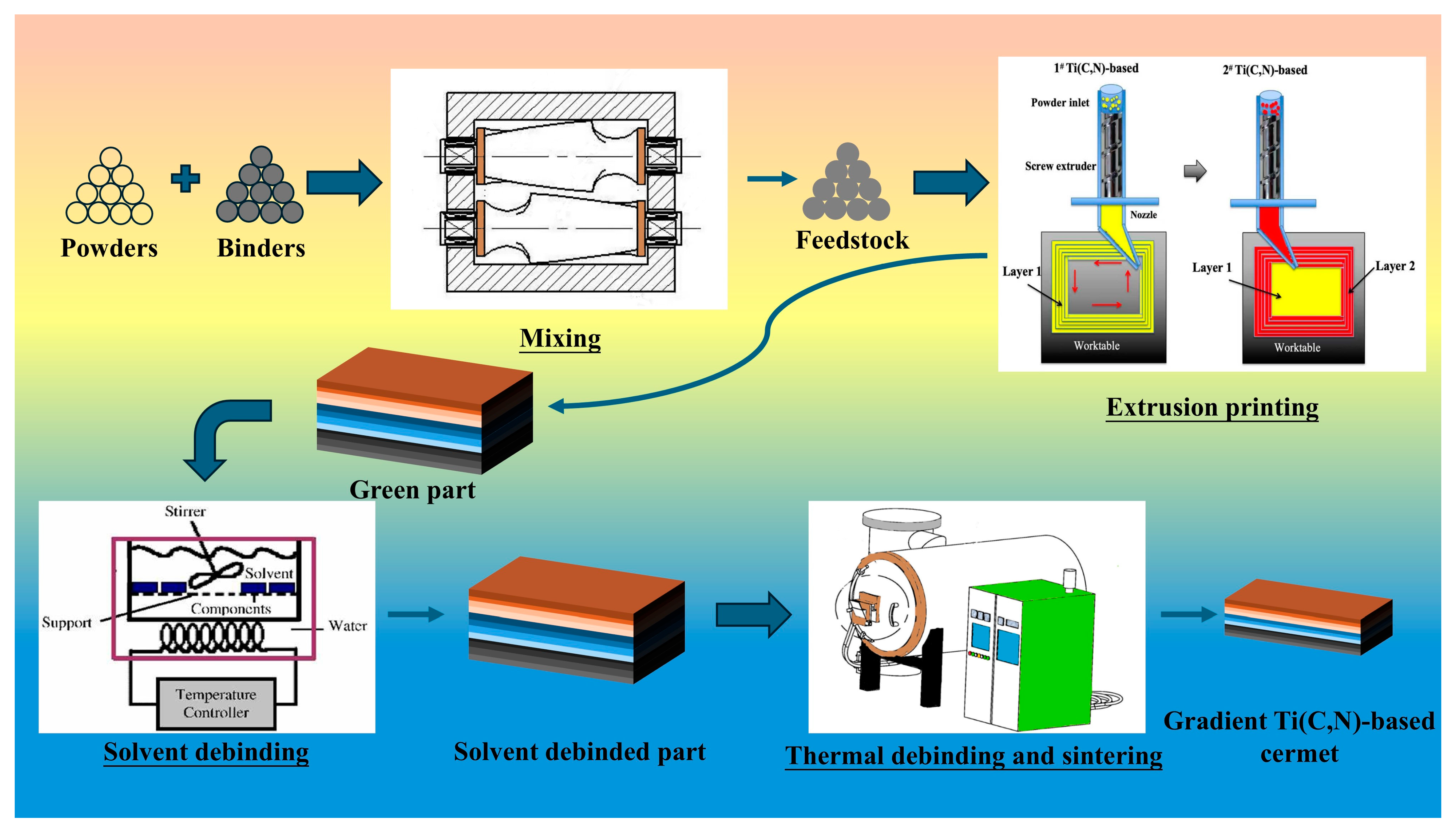
Figure 1. Scheme of gradient Ti(C,N)-based cermet production using powder extrusion additive manufacturing.
Metals 14 01161 g001
Figure 2. Morphology images of the printed parts: (a) macroscopic surface morphology; (b) SEM surface images.
Metals 14 01161 g002
Figure 3. Effect of solvent debinding parameters on the mass loss of binders.
Metals 14 01161 g003
Figure 4. Morphology of the solvent debinded part (2#) obtained at 60 °C for 90 h.
Metals 14 01161 g004
Figure 5. Dimension shrinkage of the printed parts (2#) during sintering.
Metals 14 01161 g005
Figure 6. Microstructure of the gradient Ti(C,N)-based cermet (2#) sintered at 1430 °C for 1.5 h: (a) cross-section morphology; (b) layer 1; (c) layer 2; (d) layer 3.
Metals 14 01161 g006
Figure 7. Microstructure of the gradient Ti(C,N)-based cermet (2#) sintered at 1500 °C for 1.5 h: (a) cross-section morphology; (b) layer 1; (c) layer 2; (d) layer 3.
Metals 14 01161 g007
Figure 8. EDS spectra of the gradient Ti(C,N)-based cermet (2#) sintered at 1500 °C for 1.5 h: (a) layer 1-A; (b) layer 2-B; (c) layer 3-C; (d) layer 3-D.
Metals 14 01161 g008
Figure 9. Fracture surface morphology of the specimens (2#) after bending strength test: (a) surface morphology; (b) layer 1; (c) layer 2; (d) layer 3.
Metals 14 01161 g009
Figure 10. The morphology of Vickers hardness indentation for three specimens (2#). (a) specimen 1; (b) specimen 2; (c) specimen 3.
Metals 14 01161 g010
Table 1. Chemical composition of gradient Ti(C,N)-based cermets.
Ti(C,N) [wt.%]Co [wt.%]Ni [wt.%]WC [wt.%]MoC [wt.%]TaC [wt.%]NbC [wt.%]CrC [wt.%]
Layer 166.59955410.5
Layer 258141455310
Layer 3502020342.500.5
Table 2. Chemical composition in marked area (2#) detected by SEM-EDS.
Ti, C, N [wt.%]Co [wt.%]Ni [wt.%]W [wt.%]Mo [wt.%]
Layer 1-A1000000
Layer 2-B77.040012.7610.2
Layer 3-C81.88009.518.61
Layer 3-D45.6327.2223.312.461.38
Disclaimer/Publisher’s Note: The statements, opinions and data contained in all publications are solely those of the individual author(s) and contributor(s) and not of MDPI and/or the editor(s). MDPI and/or the editor(s) disclaim responsibility for any injury to people or property resulting from any ideas, methods, instructions or products referred to in the content.