Article

The Evolution of Cube Texture in Directionally Solidified Fe-3.0 wt. % Si Alloy Assisted by a High Static Magnetic Field

State Key Laboratory of Advanced Special Steel & Shanghai Key Laboratory of Advanced Ferrometallurgy, School of Materials Science and Engineering, Shanghai University, Shanghai 200072, China
*
Authors to whom correspondence should be addressed.
Metals 2024, 14(11), 1264; https://doi.org/10.3390/met14111264
Submission received: 14 October 2024 / Revised: 1 November 2024 / Accepted: 5 November 2024 / Published: 7 November 2024
(This article belongs to the Section Crystallography and Applications of Metallic Materials)

Abstract

:
The effect of a high static magnetic field (HSMF) on the evolution of cube texture in directionally solidified Fe-3.0 wt. % Si alloy was studied. The results show that the <001> crystal orientation of an α-Fe single crystal was parallel to the direction of the HSMF, and a sharp cube texture was successfully formed in the final ingot. With the increase in growth speed, the main texture of the Fe-3.0 wt. % Si alloy evolved in the way of <001>→<081>→<120> along the pulling direction when an HSMF was applied. The orientation transition was attributed to the magnetocrystalline anisotropy of the α–Fe crystal during the directional solidification process. As a result of texture optimization, the specimens with an HSMF had higher saturation magnetization and permeability than the sample without an HSMF. Furthermore, a new creative method to tailor the cube texture of Fe-based alloys during the directional solidification process assisted by an HSMF is proposed.

1. Introduction

Silicon steels are widely used for electromagnetic equipment, such as electrical motors and iron core materials. Superior magnetic properties such as low magnetic loss and high magnetic permeability are essential performance evaluation criteria for electrical steels [1]. The superior magnetic properties of silicon steel are usually achieved by adjusting the crystallographic texture [2]. Zhang et al. [3] reported that the strong {100}<0vw> texture is desired for silicon steels, especially for electrical machinery cores. In particular, among the {100} textures, a cube texture ({100}<001>) with two <001> directions parallel to the rolling and transverse direction (RD, TD), respectively, is highly demanded for electrical steels [4]. Although the cube texture in silicon steel is very attractive, there is still no efficient way to prepare high-performance silicon steel. Most of the previous studies aiming to obtain the cube recrystallization texture have focused on the hot/cold rolling and annealing process. For example, Jiao et al. [5] obtained strong cube ({100}<001>) and Goss ({110}<001>) textures in the final steel sheets with vacuum induction melting and annealing by the twin-roll strip casting process. Cheng et al. [6] proposed that the main factors that influence the development of the cube texture of columnar-grain silicon steel were the hot/cold rolling reduction rate and the original cube texture. Zhou et al. [7] studied the {100} texture induced by pulsed electric current and rapid heating. Cube recrystallization was developed after annealing at high temperatures. Zou et al. [8] observed that the cube texture could be formed through the cold rolling and recrystallization process from the initial {001} columnar-grained electrical steel and investigated the relationship of cold rolling reduction and the angles of deviation from the ideal cube orientation. Also, Mehdi et al. [9] reported another possible method involving inclined cold rolling and subsequent high-temperature annealing and found that the cube grains can be retained during the grain growth process and form a cube texture in the final annealed sheets. Special manufacturing techniques were also attempted to produce the cube texture in electrical steel, such as the cross-rolling [10] and the phase transformation method [11]. However, all the above-mentioned methods are inseparable from complicated processes such as rolling and annealing. These processes, unfortunately, are time-consuming and not suitable for brittle high-silicon steel. Therefore, a more efficient process for fabricating cube-texture silicon steel is highly desired.
In recent decades, a high static magnetic field (HSMF) has been widely used in the solidification of metal materials [12]. It is well known that the application of an external HSMF can affect the growth behavior of crystals [13] and align the phase [14] with a remarkable magnetocrystalline anisotropy. Dong et al. [15] studied the effects on the orientation of the peritectic (Tb, Dy) Fe-2 phase along the <111> direction in an HSMF. Tang et al. [16] obtained aligned microstructures near the transition growth regions of alloys between two different growth velocities in the Al-Fe alloy. They draw the conclusion that the evolution of the eutectic growth behavior caused by the high magnetic fields can be attributed to suppression of convection force. Moreover, the easy magnetization axis of the crystal can also be aligned along the solidification direction during directional solidification [17]. Therefore, the above works show that the texture of the alloy during the solidification process can be controlled by an HSMF and directional solidification technology, thus achieving the purpose of regulating the magnetic properties of silicon steel. The effect of an HSMF on the growth of an α-Fe crystal during bulk solidification has been studied in our previous study [18]. It was observed that an axial HSMF induced the easy magnetization axis of the α-Fe crystal oriented toward the direction of the HSMF, and a sharp Goss texture was obtained under a certain magnetic flux density (MFD).
In the present work, the effect of an HSMF on the microstructure and crystallographic orientation of Fe-3.0 wt. % Si alloy during directional solidification was studied by the electron backscatter diffraction (EBSD) technique. The study aimed at exploring the evolution of cube texture in Fe-based alloys under various MFDs and crystal growth speeds. The MFD can be adjusted manually, and the growth speed was controlled by a withdrawing device. The effects of MFD and growth speed on the microstructure and crystallographic orientation were studied, respectively. Based on the magnetocrystalline anisotropy, a new efficient method to tailor the cube texture and optimize the magnetic properties of electrical steel by directional solidification combined with an HSMF was proposed. This method can avoid the complex rolling and annealing process and realize short-process technology.

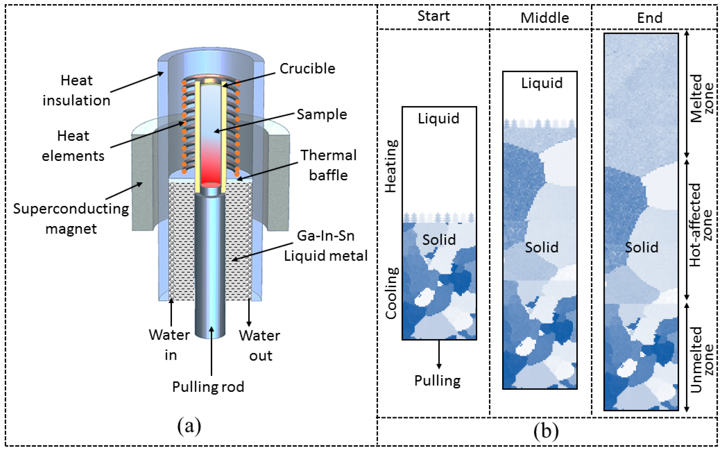
2. Experimental Procedure

In this study, the alloy was prepared with high-purity Fe (99.99 wt. %) and Si (99.99 wt. %) particles in a vacuum induction furnace and then cast into a cylindrical bar 4 mm in diameter. The dimensions of the directional solidification samples were 180 mm in length and 4 mm in diameter. Experiments with an axial HSMF were carried out in an argon atmosphere using the Bridgman apparatus [19] as shown in Figure 1a. This set of devices was mainly composed of a superconducting magnet, a directional solidification furnace, a withdrawing device, and a temperature controller. The temperature gradient in the furnace was controlled by adjusting the heating temperature. Three regions, the unmelted zone, hot-affected zone which is similar with that reported by Zhang et al. [20], and melted zone, can be identified from the bottom to the top in Figure 1b. The temperature gradient was maintained at 53 K/cm at a furnace temperature of 1873 K. The pulling speed was controlled by a withdrawing device and it ranged from 1.0 μm/s to 103 μm/s. To investigate the dendrite growth morphology of the mushy zone, the samples can be quickly pulled into the Ga-In-Sn liquid metal pool for the quenching process.
Metallographic samples, which were cut from the longitudinal and transverse section of the directionally solidified ingot, were obtained by the conventional metallographic method. After the sample was polished, it was corroded with 4% nitrate alcohol to observe the metallography. The microstructure was examined by using an optical microscope (Leica DM 6000, Germany Leica). Prior to EBSD characterization, the sample was subjected to electrochemical polishing using 20% perchlorate alcohol. The EBSD (HKL-Channel 5, Britan Oxford) facility attached to an Apollo 300 (Britan CamScan) scanning electron microscope was used to investigate the crystallographic orientation of the samples. The inverse polar figure (IPF) was used to characterize the distribution of the crystal direction parallel to the appearance direction of a feature in the crystallographic space. The polar figure (PF) can show the distribution of specific crystal faces of each grain in different directions in the sample. Orientation distribution function (ODF) can express the orientation distribution of the whole space, so the information is more comprehensive. To investigate the magnetic properties, the hysteresis loops of samples with dimensions of 2 × 2 × 3 mm3 were measured by using the vibrating sample magnetometer (VSM, Lakeshore 7407 American Lakeshore). For the demagnetization factor, we made a standard sample of the same size with pure Ni; input the density, quality, and other data of our sample; and then deducted the measured magnetic property results from this standard sample. The direction of the magnetic field applied to the sample is the same as the pulling direction when the magnetic properties are measured.

3. Results and Discussion

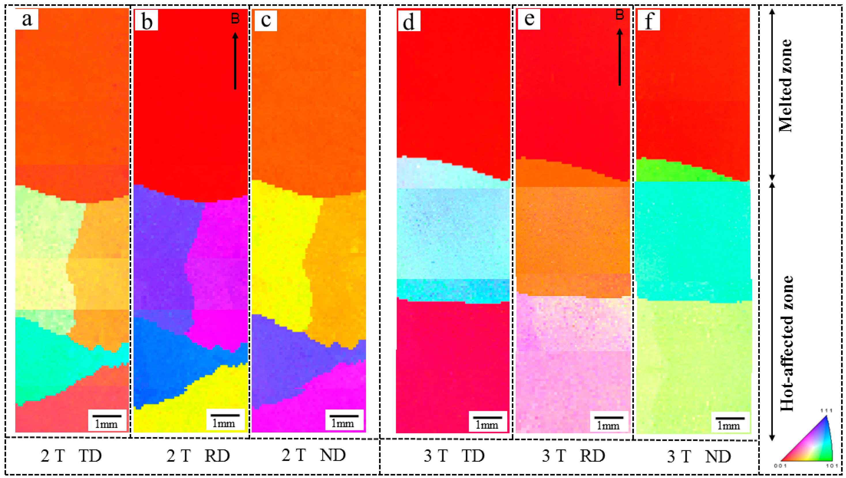
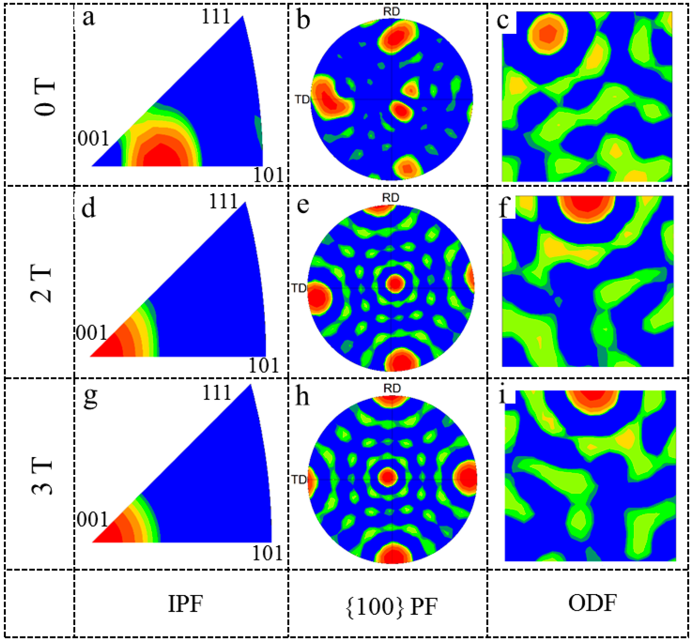
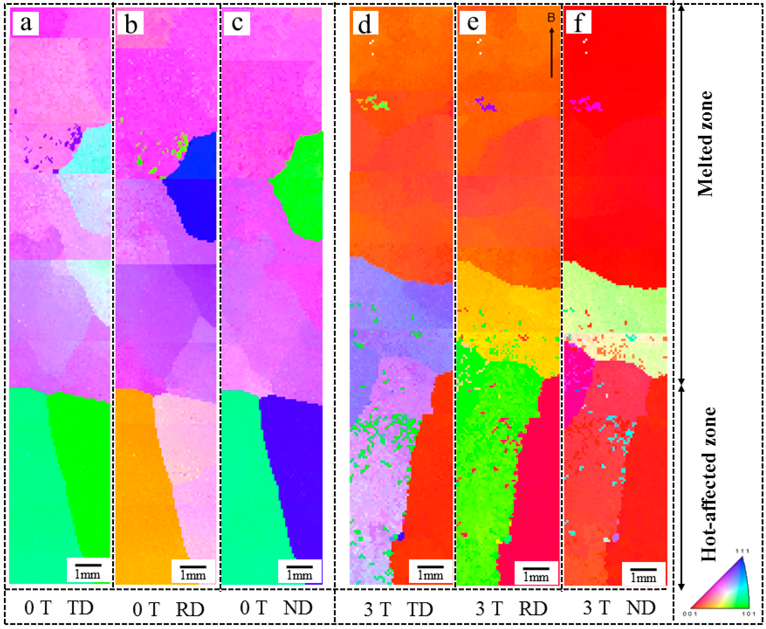
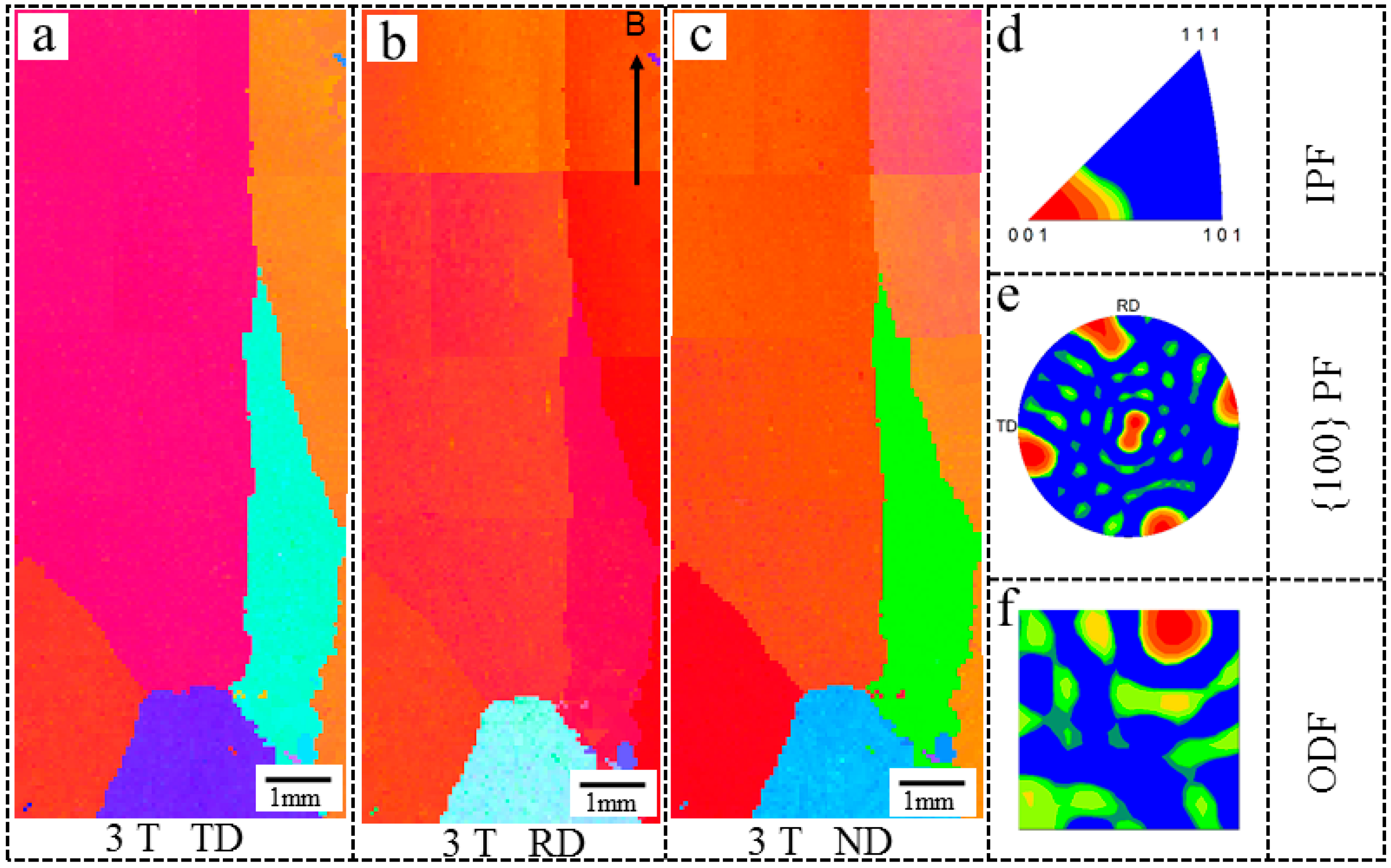
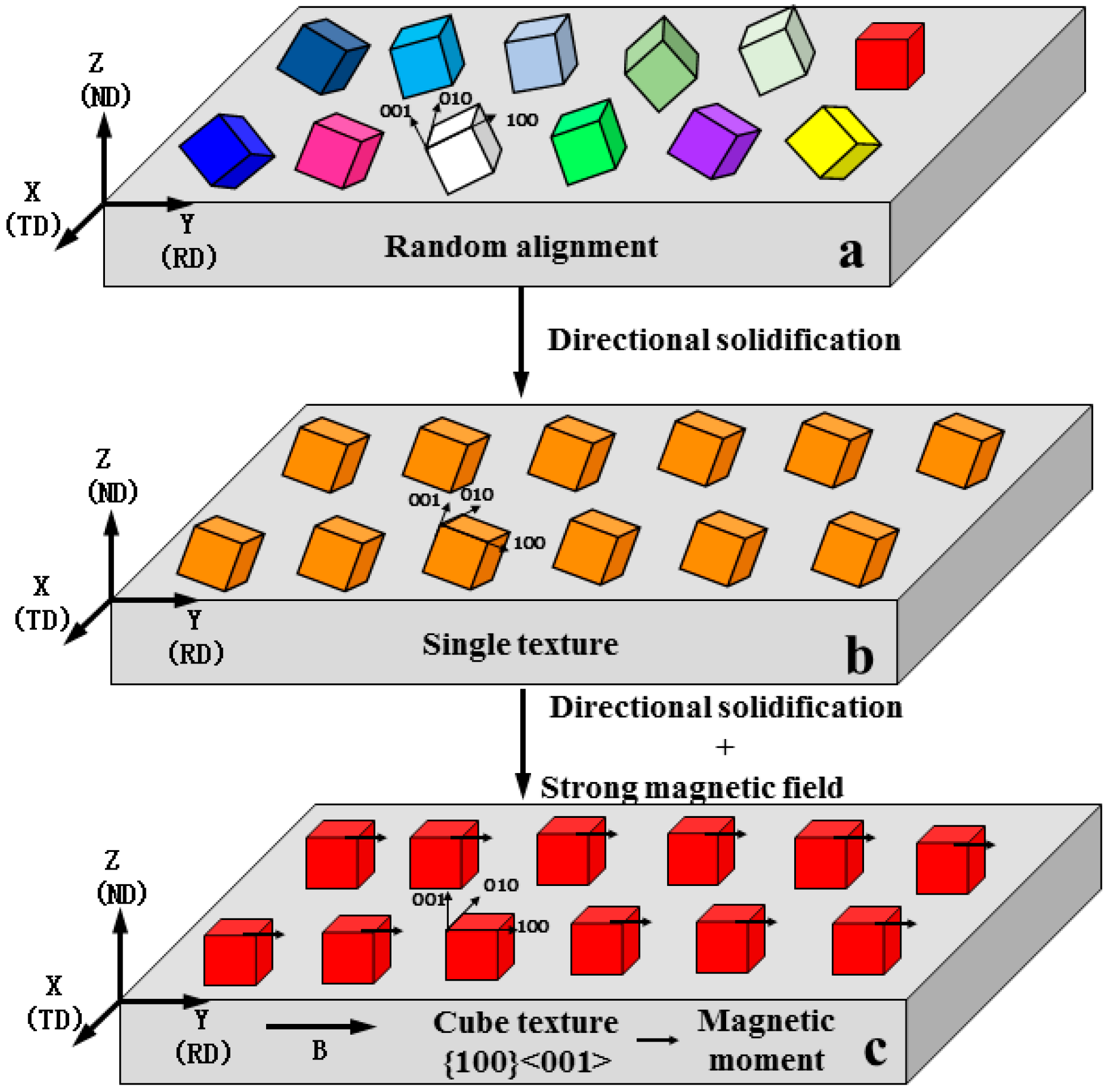
3.1. The Effect of MFD and Growth Speed on the Orientation Selection of α-Fe Crystals

During the directional solidification of Fe-3.0 wt. % Si alloy, the primary α–Fe phase nucleates from the liquid and gradually grows. Since the nucleation and growth of the grains are affected by the energy of the system [21], the behavior of an α–Fe crystal during directional solidification will also be influenced by an HSMF. To illustrate the HSMF effects on the α–Fe crystal, the specimens were solidified under different MFDs. Figure 2 shows the optical micrograph and EBSD result of the sample solidified at a growth velocity of 10 μm/s. In this case, which was treated without an HSMF, only a suspected single-crystal preferentially grew along the heat flow direction in the melted zone. Along the pulling direction, the grain orientation of the solidified structure in the longitudinal section is <130>, as shown in Figure 2d. This observation is similar to the experimental result reported by Fu et al. [22]. To elucidate the grain orientation evolution during the directional solidification process, the samples were analyzed by EBSD. Figure 2c–e are the EBSD maps characterized from three different detected directions (TD, RD, and ND). A schematic diagram of the detected directions and HSMF direction is shown in Figure 2g. It is shown that the orientation of the sample is different from three detected directions, and a suspected single crystal was formed in the melted zone. The red dashed line in Figure 2b marks the transverse section prepared for the EBSD map, which is shown in Figure 2f. This further confirms that the melted zone only consists of a single crystal. Figure 3 shows the microstructure of the Fe-3.0 wt. % Si alloy fabricated under various MFDs at a growth speed of 10 μm/s. A single crystal, which was accompanied with a sharp <100> grain orientation along the pulling direction, was formed under 2 T. When the MFD increased to 3 T, this effect became more noticeable, and a sharp <100> texture also formed along the pulling direction, as shown in Figure 3e. By comparing the microstructures with and without the HSMF, it can be seen that the application of the HSMF caused the <001> crystal orientation of the grain to rotate to the RD or HSMF direction.
Figure 4 shows the IPF, PF, and ODF at Φ2 = 45° (Φ2 is an Euler angle used to describe the crystal orientation) of samples treated by various MFDs. The textures treated under an HSMF are different from the original material sample. As can be seen from the inverse figure in Figure 4a, when no HSMF is applied, the grain growth direction deviates from the <001> crystal direction significantly. According to the PF, the grain is dominated by the {116} texture. The corresponding ODF result shows that the texture is concentrated around {116} <130>. When the MFD increases to 2 T, the grain grows in the direction of <001> along the magnetic field, and when the MFD continued to increase to 3 T, the result is similar. According to the corresponding ODF in Figure 4, with increasing MFD, the texture rotates toward quasi-{100} <001> (deviation 3° from ideal orientation) and finally to {100} <001>. It is deduced that the HSMF caused the change in the single crystal orientation in the melted zone, and the HSMF favors the occurrence of the {100} texture at the specific growth speed. Figure 5 shows the EBSD maps of the longitudinal microstructures in directionally solidified Fe-3.0 wt. % Si alloy at a growth speed of 50 μm/s with and without a 3 T HSMF. In the absence of an HSMF, the specimen consists of two parallel columnar grains at the hot-affected zone. The grain grows in the direction of <241> along the pulling direction in the melted zone, as shown in Figure 5b. For the case of 3 T, in the initial stage of solidification, several columnar crystals grow along the magnetic field direction and eventually become a single grain along the magnetic field direction in the melting zone. This is a strong <081> fiber texture, as shown in Figure 5e. As can be seen from the IPF in Figure 6, the growth direction of the grain changes from <241> to close to <001> after the magnetic field is applied. The corresponding PF shows that the grain is dominated by the {100} texture after the magnetic field is applied. As shown in Figure 6d, it is found that the microstructure formed a strong {112} <241> texture in the sample treated with 0 T, which deviates far from the favorable texture. However, a strong {118} <081> (deviation 8° from ideal cube orientation) texture was formed in the case of 3 T, as shown in Figure 6h.
The above results show that the pulling speed affected the microstructure and texture of the Fe-3.0 wt. % Si alloy during directional solidification. Thus, an experiment was carried out at a growth speed of 100 μm/s with a 3 T HSMF. The results show that the width of the columnar grains decreased from 2 mm to 1 mm in the hot-affected zone when the growth speed increased from 10 to 100 μm/s. In the melted zone, the straight grain boundary was formed when the growth speed was 100 μm/s. The columnar grains are homogeneous with a width of 1 mm to 3 mm. A strong <120> fiber texture was formed along the direction of the HSMF, as shown in Figure 7a. The texture consists mainly of the {001}<120> texture, which slightly deviated from the ideal orientation. Thus, the growth speed was proved to have a prominent effect on the crystallographic orientation of the Fe-3.0 wt. % Si alloy. With increasing growth speed under 3 T, the main texture of the sample evolved in the way of <001>→<081>→<120> along the pulling direction. It is concluded that a 3 T HSMF at a growth speed of 10 μm/s were the optimum parameters to form a single crystal with a sharp cube texture in the Fe-3.0 wt. % Si alloy.
The above investigation indicated that the application of an axial HSMF induced the <001> crystal direction to grow along the pulling direction during the directional solidification. This was attributed to two main magnetic effects that affect the directionally solidified microstructure assisted by an axial HSMF. One is the magnetic moment, which is caused by the magnetocrystalline anisotropy. The magnetic moment tends to align the grains with the easy magnetic axis of the crystal along the direction of the HSMF [23]. Moreover, due to the Seebeck effect [24], a thermoelectric current will be generated around the dendrite in the mushy zone. If an axial HSMF is applied, the interaction between the thermoelectric current and the HSMF produces the thermoelectric force (TEMF). In the process of directional solidification, there is a temperature gradient in the molten metal, and the interaction between this temperature gradient and the magnetic field will produce a force TEMF. This force is particularly important during metal solidification, which will destroy the dendrite array [25] and induce columnar-to-equiaxed transition [26]. These two magnetic effects may occur at the same time and change the growth of the crystal during the directional solidification assisted by the HSMF. Therefore, it is essential to investigate the solid–liquid interfacial morphology in the mushy zones of the samples. Figure 8 shows the solid–liquid interfacial morphologies of samples both with and without an axial HSMF. The regular planar interface was observed with the absence of an HSMF. However, the regular columnar dendrites grew along the direction of the HSMF when the MFD was 3 T. There is no dendrite fragmentation or distortion in the mushy zone. It is deduced that TEMF has little effect on crystal orientation. Moreover, the EBSD result shows that no stray grain appears under the HSMF. It is concluded that the modification of the crystal orientation is attributed to the magnetic orientation effect during directional solidification assisted by an axial HSMF.
Previous investigations have proven that the HSMF can adjust the dendrite morphology and crystal growth during directional solidification. Theoretically, the anisotropic magnetic energy of a crystal is the driving force for the rotation of a grain to its lowest energy state. In an HSMF, the anisotropic magnetic energy (ΔE) of the crystal can be expressed by the following equation [16]:
Δ E = V ( χ a χ b ) 1 / 2 μ 0 B 2
where V is the crystal volume, B is the externally imposed MFD, χ is the volume susceptibility of the specified crystal directions, and μ0 is the vacuum permeability constant, assuming that χa is the magnetic susceptibility of the easy magnetization axis, while χb is the magnetic susceptibility of the difficult magnetization axis. In the solidification process, α-Fe is paramagnetic when it is above the Curie point. When χa > χb, it can be seen from Formula (1) that ΔE > 0, and the magnetic anisotropy energy difference will cause the crystal to rotate in the liquid phase. This will cause the crystal orientation to change until the crystal has the lowest energy in an HSMF [27]. For a ferrite crystal, <100> is its easy magnetic axis, and it possesses a distinct magnetic anisotropy. Moreover, the degree of magnetic alignment is also related to liquid viscosity, crystal nucleus size, and orientation time [28]. As a result, the grains orientated with the easy magnetization axis <100> crystal orientation along the direction of the HSMF. Moreover, the destabilization of the melt can be significantly suppressed by the effect of the HSMF [29], which affects the heat and mass transfer process significantly and is beneficial for the alignment of the α-Fe grain. When the growth velocity was 10 μm/s, the strength of the cube texture increased with increasing MFD. When the growth velocity increased to 50 μm/s or 100 μm/s, the influence of the HSMF on texture optimization was reduced because the time of the magnetic moment acting on the grains is insufficient to align the <100> crystal orientation of the α-Fe grain totally along the direction of the HSMF. According to theoretical analysis, the enhancement of cube texture mainly results from the magnetic moment orientation mechanism. The above investigation has proven that the application of an axial HSMF during the directional solidification of Fe-Si alloy was in favor of triggering the formation of a cube texture. A schematic illustration of cube texture and grain alignment is shown in Figure 9. This provides a new creative way to tailor the cube texture of Fe-based alloys during directional solidification assisted by an HSMF.

3.2. Effect of an Axial HSMF on Magnetic Properties

The microstructure and EBSD results demonstrate that an HSMF has a significant influence on crystal orientation during the directional solidification process. Thus, physical properties, which are determined by the microstructure, should be investigated accordingly. Hysteresis loops of the directionally solidified ingot were measured by VSM equipment. The plane measured in this study is parallel to the withdrawing direction, and the magnetic property results are shown in Figure 10. In Figure 10, the vertical axis is the magnetization, and the horizontal axis is the magnetic field intensity. When the magnetic field intensity is about 15,000 Oe, the saturation magnetization (Ms) reaches saturation gradually. As can be seen from the table in Figure 10, the Ms of the specimens at 10 μm/s increase from 212.2 to 213.8 emu/g as the MFD increases from 0 to 3 T. When growth velocity was 50 μm/s under 0 T, the Ms of the specimens is 211.8 emu/g, which is the lowest. This study found that applying a magnetic field does cause an increase in the Ms, but this increase rate is quite low, probably because it is insensitive to the texture and microstructure [30]. However, further clarification of the evolving rules of Ms and further improvement plans will be carried out in our future work. Next, we will focus on the influence of experimental parameters on permeability, which is also an important indicator of magnetic properties. Wang et al. [31] reported that magnetization was divided into two stages, starting with the magnetic domain wall movement and followed by the magnetic domain rotation. In the beginning, the magnetic domain wall motion is dominant and Ms increases quickly. Then, the magnetic domains begin to rotate as a contribution of Ms, and the value of Ms increases slowly. According to Stojakovic et al. [32], the {100} texture components are conducive to improving magnetic properties, while the {111} texture components have the opposite effect. Based on the microstructure and EBSD results, the HSMF governs the crystallographic orientation of the α-Fe phase and causes further changes in magnetic properties. When growth velocity was 10 μm/s, the texture was concentrated around {116}<130> under 0 T. With increasing MFD, the texture rotated towards the quasi-{100}<001> and finally towards the {100}<001>. The sample at 3 T showed a higher susceptibility value than the sample at 0 T, which is attributed to the favorable {001} texture. When growth velocity increased to 50 μm/s, a strong {112}<241> texture was formed under 0 T, which deviates far from the favorable texture. As a result, permeability is the lowest due to its detrimental texture. With the increase in MFD, the {100}<001> texture component was strengthened and led to the increase in permeability at the same growth velocity. In this paper, the experimental parameters for the optimal magnetic performance are 10 μm/s for the pulling speed and 3 T for the MFD.
In summary, the enhancement of magnetic properties is attributed to a uniform and sharp cube texture in this study. Directional solidification technology assisted by an HSMF is beneficial to fabricate cube texture materials with an excellent soft magnetic property. Therefore, the present study provides a novel method to tailor the cube texture of Fe-based alloys during the directional solidification process assisted by an HSMF. This technique is simple and may promote the development of electric power generation.

4. Conclusions

In this study, Fe-3.0 wt. % Si alloy with a sharp cube texture was successfully produced by using directional solidification technology combined with an HSMF. The influence of MFD and growth speed on the crystallographic orientation and magnetic properties of the Fe-3.0 wt. % Si alloy was studied. Conclusions are summarized as follows:
Fe-3.0 wt. % Si alloy with superior magnetic performance has been successfully processed through the formation of the cube ({100}<001>) texture by using directional solidification technology combined with an HSMF.
A single crystal preferentially grew along the heat flow direction in the melted zone. When growth velocity was 10 μm/s, the texture was concentrated around {116}<130> under 0 T. With increasing MFD, the texture rotated towards quasi-{100}<001> and finally to {100}<001>.
The growth speed played an important role in the crystal orientation of the directionally solidified Fe-3.0 wt. % Si alloy. With the increase in the growth speed, the main texture evolved in the way of <001>→<081>→<120> along the pulling direction under 3 T.
The application of an axial HSMF is beneficial for the production of a sharp cube texture during the directional solidification of Fe-Si alloy. This is closely related to the effect of an HSMF on the magnetocrystalline anisotropy of α-Fe crystals.

Author Contributions

Conceptualization, Y.Z., M.F. and W.L.; methodology, Z.C. and W.L.; software, Z.C. and M.F.; validation, H.L. and T.Z.; formal analysis, C.L., Z.C. and W.L.; investigation, H.L. and Z.C.; resources, Y.Z. and T.Z.; data curation, C.L. and H.L.; writing—original draft preparation, C.L. and B.Z.; writing—review and editing, B.Z., C.L. and M.F.; visualization, Z.C. and B.Z.; supervision, T.Z. and H.L.; project administration, Y.Z. and B.Z.; funding acquisition Y.Z. and T.Z. All authors have read and agreed to the published version of the manuscript.

Funding

The authors gratefully acknowledge the financial support of the National Natural Science Foundation of China (U23A20607, 52304404, U1732276), the Natural Science Foundation of Shanghai (21ZR1424400), and the Changjiang Scholars Program of China, China Association for Science and Technology Young Talent Support Project.

Data Availability Statement

The raw data required to reproduce these findings cannot be shared at this time as the data also form part of an ongoing study.

Conflicts of Interest

The authors declare no competing interests.

References

  1. Takada, Y.; Abe, M.; Masuda, S.; Inagaki, J. Commercial scale production of Fe-6.5 wt.% Si sheet and its magnetic properties. J. Appl. Phys. 1998, 64, 5367–5369. [Google Scholar] [CrossRef]
  2. Ouyang, G.; Chen, X.; Liang, Y.X.; Macziewski, C.; Cui, J. Review of Fe-6.5 wt.% Si high silicon steel-A promising soft magnetic material for sub-kHz application. J. Magn. Magn. Mater. 2019, 481, 234–250. [Google Scholar] [CrossRef]
  3. Zhang, Y.X.; Lu, X.; Yuan, G.; Wang, Y.; Fang, F.; Zhang, X.; Wang, G. Texture and microstructure evolution during different rolling methods in strip-cast grain-oriented 6.5% Si steel. J. Magn. Magn. Mater. 2020, 499, 166256. [Google Scholar] [CrossRef]
  4. Xu, Y.B.; Zhang, Y.X.; Wang, Y.; Li, C.G.; Cao, G.M.; Liu, Z.Y.; Wang, G.D. Evolution of cube texture in strip-cast non-oriented silicon steels. Scr. Mater. 2014, 87, 17–20. [Google Scholar] [CrossRef]
  5. Jiao, H.T.; Xu, Y.B.; Zhao, L.Z.; Misra, R.D.K.; Tang, Y.C.; Liu, D.J.; Hu, Y.; Zhao, M.J.; Shen, M.X. Texture evolution in twin-roll strip cast non-oriented electrical steel with strong Cube and Goss texture. Acta Mater. 2020, 199, 311–325. [Google Scholar] [CrossRef]
  6. Cheng, L.; Yang, P.; Fang, Y.P.; Mao, W.M. Preparation of non-oriented silicon steel with high magnetic induction using columnar grains. J. Magn. Magn. Mater. 2012, 324, 4068–4072. [Google Scholar] [CrossRef]
  7. Zhou, M.C.; Zhang, X.F. Regulating the recrystallized grain to induce strong cube texture in oriented silicon steel. J. Mater. Sci. Technol. 2022, 96, 126–139. [Google Scholar] [CrossRef]
  8. Zou, X.; Liu, Q.; Qiu, S. A Study on the Formation of Fiber Texture in the Subsurface Layer of Hot-Rolled Plate of 3.2% Si Grain Oriented Steel. Metals 2023, 13, 1597. [Google Scholar] [CrossRef]
  9. Mehdi, M.; He, Y.L.; Hilinski, E.J.; Kestens, L.A.I.; Edrisy, A. The evolution of cube ({001}<100>) texture in non-oriented electrical steel. Acta Mater. 2020, 185, 540–554. [Google Scholar]
  10. Sonboli, A.; Mohammad, M.R.; Edris, H.; Szpunar, J.A. Effect of deformation route and intermediate annealing on magnetic anisotropy and magnetic properties of a 1 wt.% Si non-oriented electrical steel. J. Magn. Magn. Mater. 2015, 385, 331–338. [Google Scholar] [CrossRef]
  11. Zhang, L.W.; Yang, P.; Mao, W.M. Opposite relationship between orientation selection and texture memory in the deformed electrical steel sheets during α→γ→α transformation. J. Mater. Sci. Technol. 2017, 33, 1522–1530. [Google Scholar] [CrossRef]
  12. Rango, P.D.; Lees, M.; Lejay, P.; Sulpice, A.; Tournier, R.; Ingold, M.; Germi, P.; Pernet, M. Texturing of magnetic materials at high temperature by solidification in a magnetic field. Nature 1991, 349, 770–772. [Google Scholar] [CrossRef]
  13. Zheng, T.X.; Zhong, Y.B.; Lei, Z.S.; Ren, W.L.; Ren, Z.M.; Wang, H.; Wang, Q.L.; Debray, F.; Beaugnon, E.; Fautrelle, Y. Effects of high static magnetic field on crystal orientation and magnetic property of Bi-5 wt.% Zn alloys. Mater. Lett. 2015, 140, 68–70. [Google Scholar] [CrossRef]
  14. Guo, X.Y.; Liu, T.; Zhang, B.Z.; Dong, M.; Yang, H.Z.; Yuan, S.; Wang, Q. Microstructure, residual stress and magnetic properties of Tb0.27Dy0.73Fe1.95 alloy heat treated in high magnetic field. J. Magn. Magn. Mater. 2023, 588, 171472. [Google Scholar] [CrossRef]
  15. Dong, M.; Liu, T.; Guo, X.Y.; Dong, S.L.; Wang, T.; Wang, Q. Crystal orientation induced by high magnetic fields during peritectic reaction of alloys. Mater. Charact. 2022, 183, 111608. [Google Scholar] [CrossRef]
  16. Tang, P.; Tian, Y.; Liu, S.; Lv, Y.; Xie, Y.; Yan, J.; Liu, T.; Wang, Q. Microstructure development in eutectic Al-Fe alloy during directional solidification under high magnetic fields at different growth velocities. J. Mater. Sci. 2021, 56, 16134–16144. [Google Scholar] [CrossRef]
  17. Xiao, Y.; Liu, T.; Tong, Y.; Dong, M.; Li, J.; Wang, J.; Wang, Q. Microstructure evolution of peritectic Al-18 at% Ni alloy directionally solidified in high magnetic fields. J. Mater. Sci. Technol. 2021, 76, 51–59. [Google Scholar] [CrossRef]
  18. Liu, C.M.; Zhong, Y.B.; Shen, Z.; Zheng, T.X.; Dong, L.C.; Ren, W.L.; Lei, Z.S.; Ren, Z.M. Effect of an axial high static magnetic field on the crystal orientation and magnetic property of Fe-4.5 wt.% Si alloy during bulk solidification. Mater. Lett. 2019, 247, 189–192. [Google Scholar] [CrossRef]
  19. Hou, Y.; Shuai, S.S.; Dong, Y.H.; Xuan, W.D.; Wang, J.; Zhang, Z.Q.; Ren, X.F.; Ren, Z.M. Effect of thermoelectric magnetic convection on shrinkage porosity at the final stage of solidification of GCr18Mo steel under axial static magnetic field. Metall. Mater. Trans. B 2019, 50, 881–889. [Google Scholar] [CrossRef]
  20. Zhang, Z.W.; Chen, G.; Bei, H.B.; Li, F.; Ye, F.; Chen, G.L.; Liu, C.T. Directional recrystallization and microstructures of an Fe–6.5 wt.% Si alloy. J. Mater. Res. 2009, 24, 2654–2660. [Google Scholar] [CrossRef]
  21. Tournier, R.F.; Beaugnon, E. Texturing by cooling a metallic melt in a magnetic field. Sci. Technol. Adv. Mat. 2009, 10, 014501. [Google Scholar] [CrossRef] [PubMed]
  22. Fu, H.D.; Zhang, Z.H.; Jiang, Y.B.; Xie, J.X. Improvement of magnetic properties of an Fe–6.5 wt.% Si alloy by directional solidification. Mater. Lett. 2011, 65, 1416–1419. [Google Scholar] [CrossRef]
  23. Liu, C.M.; Zhong, Y.B.; Shen, Z.; Zheng, T.X.; Dong, L.C.; Ren, W.L.; Lei, Z.S.; Ren, Z.M. Magnetic field–dependent microstructure evolution and magnetic property of Fe–6.5 Si–0.05 B alloy during solidification. J. Mater Res. 2019, 34, 4076–4084. [Google Scholar] [CrossRef]
  24. Du, D.-F.; Fautrelle, Y.; Ren, Z.M.; Moreau, R.; Li, X. Effect of a high magnetic field on the growth of ternary Al-Cu-Ag alloys during directional solidification. Acta Mater. 2016, 121, 240–256. [Google Scholar] [CrossRef]
  25. Li, X.; Fautrelle, Y.; Ren, Z.M.; Gagnoud, A.; Zhang, Y.D.; Esling, C. Morphological instability of interface, cell and dendrite during directional solidification under strong magnetic field. J. Cryst. Growth 2011, 318, 23–27. [Google Scholar] [CrossRef]
  26. Liu, H.; Xuan, W.D.; Xie, X.L.; Li, C.J.; Wang, J.; Yu, J.B.; Li, X.; Zhong, Y.B.; Ren, Z.M. Columnar-to-equiaxed transition and equiaxed grain alignment in directionally solidified Ni3Al alloy under an axial magnetic field. Metall. Mater. Trans. A 2017, 48, 4193–4203. [Google Scholar] [CrossRef]
  27. Akiyama, J.; Asano, H.; Iwai, K. Analysis of uniaxial alignment behavior of nonmagnetic materials under static magnetic field with sample rotation. Mater. Trans. 2008, 49, 787–791. [Google Scholar] [CrossRef]
  28. Sun, Z.H.I.; Guo, M.; Vleugels, J.; Van, O.; Blanpain, B. Strong static magnetic field processing of metallic materials. Curr. Opin. Solid. St. M. 2012, 16, 254–267. [Google Scholar] [CrossRef]
  29. Ren, W.L.; Zhang, T.; Ren, Z.M.; Zhao, A.K.; Zhong, Y.B.; Guo, J.T. A dramatic increase in dendrite number for directionally solidified superalloy DZ417G with a strong static magnetic field. Mater. Lett. 2009, 63, 382–385. [Google Scholar] [CrossRef]
  30. Myung, N.V.; Park, D.Y.; Yoo, B.Y.; Sumodjo, P.T.A. Development of electroplated magnetic materials for MEMS. J. Magn. Magn. Mater. 2003, 265, 189–198. [Google Scholar] [CrossRef]
  31. Wang, S.; Liang, Y.F.; Ye, F.; Geng, G.H.; Lin, J.P. Microstructure, mechanical and magnetic properties of melt extracted Fe-6.5 wt.% Si microwires. J. Mater. Process. Technol. 2017, 249, 325–330. [Google Scholar] [CrossRef]
  32. Stojakovic, D.; Doherty, R.D.; Kalidindi, S.R.; Landgraf, F.J.G. Thermomechanical processing for recovery of desired <001> fiber texture in electric motor steels. Metall. Mater. Trans. A 2018, 39, 1738–1746. [Google Scholar]
Figure 1. (a) The schematic diagram of the directional solidification devices under an axial HSMF. (b) The schematic diagram of microstructure evolution in directional solidification experiment.
Metals 14 01264 g001
Figure 2. The microstructure and EBSD orientation maps in the sample directionally solidified at a growth speed of 10 μm/s under 0 T. (a) Optical macrostructure; (b) partial enlarged view of red dashed rectangle in (a); (c) OIM (orientation imaging microscopy) of the transverse direction (TD); (d) OIM of the rolling direction (RD); (e) OIM of the normal direction (ND); (f) transverse microstructure; (g) a schematic diagram of sample detection position and magnetic field direction. (OIM is mainly used for crystal orientation characterization of materials).
Metals 14 01264 g002
Figure 3. EBSD orientation maps in the directionally solidified Fe-3.0 wt. % Si alloy at a growth speed of 10 μm/s under various MFDs. (ac) 2 T; (df) 3 T.
Metals 14 01264 g003
Figure 4. The IPF, PF, and ODF at Φ2 = 45° of the Fe-3.0 wt. % Si alloy under various MFDs: (ac) 0 T; (df) 2 T; (gi) 3 T.
Metals 14 01264 g004
Figure 5. EBSD orientation maps in the directionally solidified Fe-3.0 wt. % Si alloy at a growth speed of 50 μm/s under various MFDs. (ac) 0 T; (df) 3 T.
Metals 14 01264 g005
Figure 6. The IPF, PF, and ODF and crystal lattice pattern at Φ2 = 45° of the Fe-3.0 wt. % Si alloy under various MFDs: (ad) 0 T; (eh) 3 T.
Metals 14 01264 g006
Figure 7. EBSD orientation maps and the IPF, PF, and ODF and crystal lattice pattern at Φ2 = 45° of the Fe-3.0 wt. % Si alloy at a growth speed of 100 μm/s under 0 T: (ac) OIM; (d) inverse figure; (e) pole figure; (f) ODF.
Metals 14 01264 g007
Figure 8. The liquid/solid interface in the longitudinal section during directional solidification at a growth speed of 10 μm/s: (a) 0 T; (b) 3 T.
Metals 14 01264 g008
Figure 9. Schematic illustration of the formation of cube texture: (a) random alignment, (b) single texture under conventional directional solidification, and (c) cube texture under HSMF combined with directional solidification.
Metals 14 01264 g009
Figure 10. (a) M-H curves of the directionally solidified ingot under various MFDs. (b) Partial enlarged view of black dashed rectangle in (a) and table of magnetic properties and experimental parameters.
Metals 14 01264 g010
Disclaimer/Publisher’s Note: The statements, opinions and data contained in all publications are solely those of the individual author(s) and contributor(s) and not of MDPI and/or the editor(s). MDPI and/or the editor(s) disclaim responsibility for any injury to people or property resulting from any ideas, methods, instructions or products referred to in the content.

