
Refill Friction Stir Spot Welding of an Al-Li Alloy: The Effects of Rotating Speed and Welding Time on Joint Microstructure and Mechanical Properties


Abstract
1. Introduction
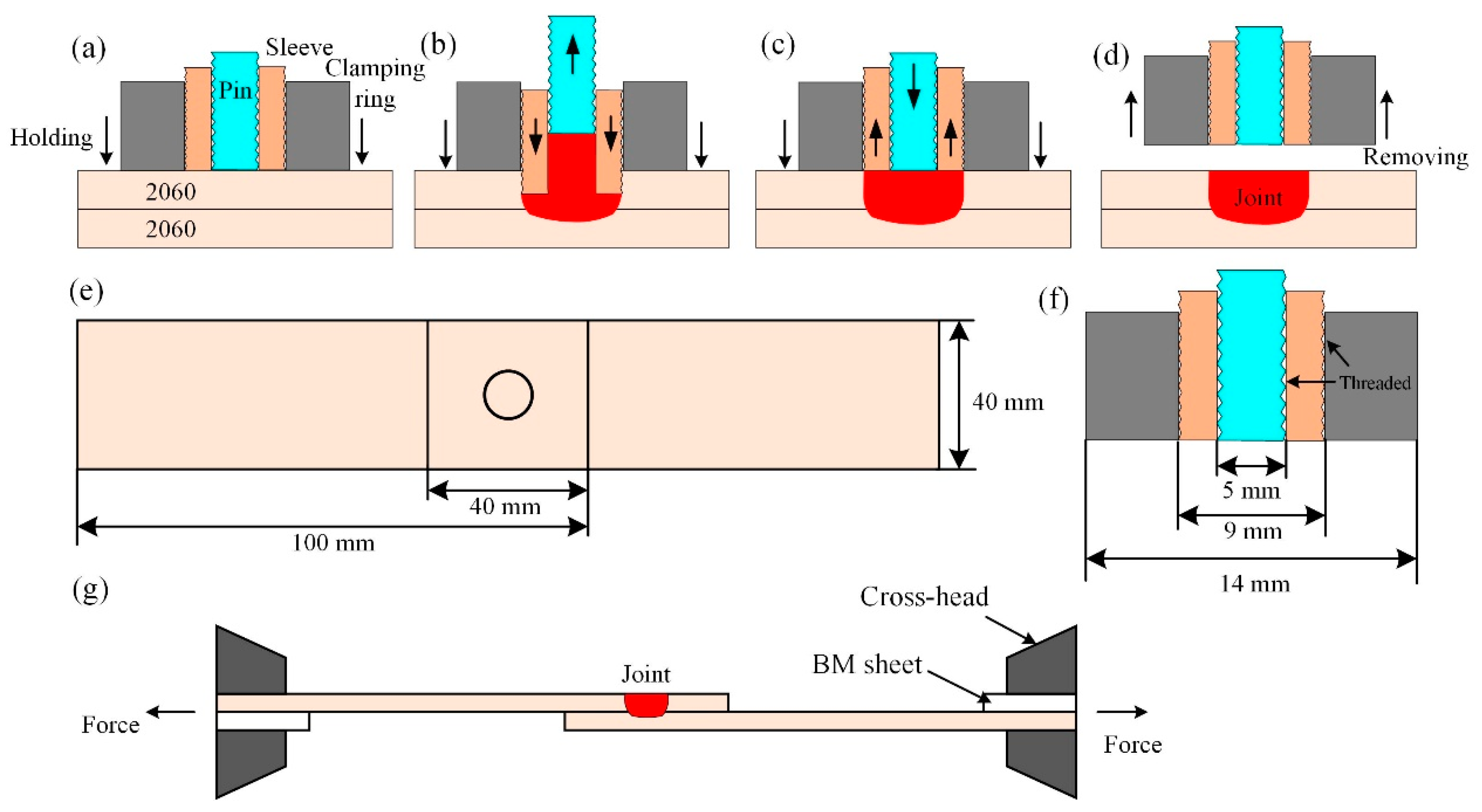
2. Experiments
3. Results and Discussions
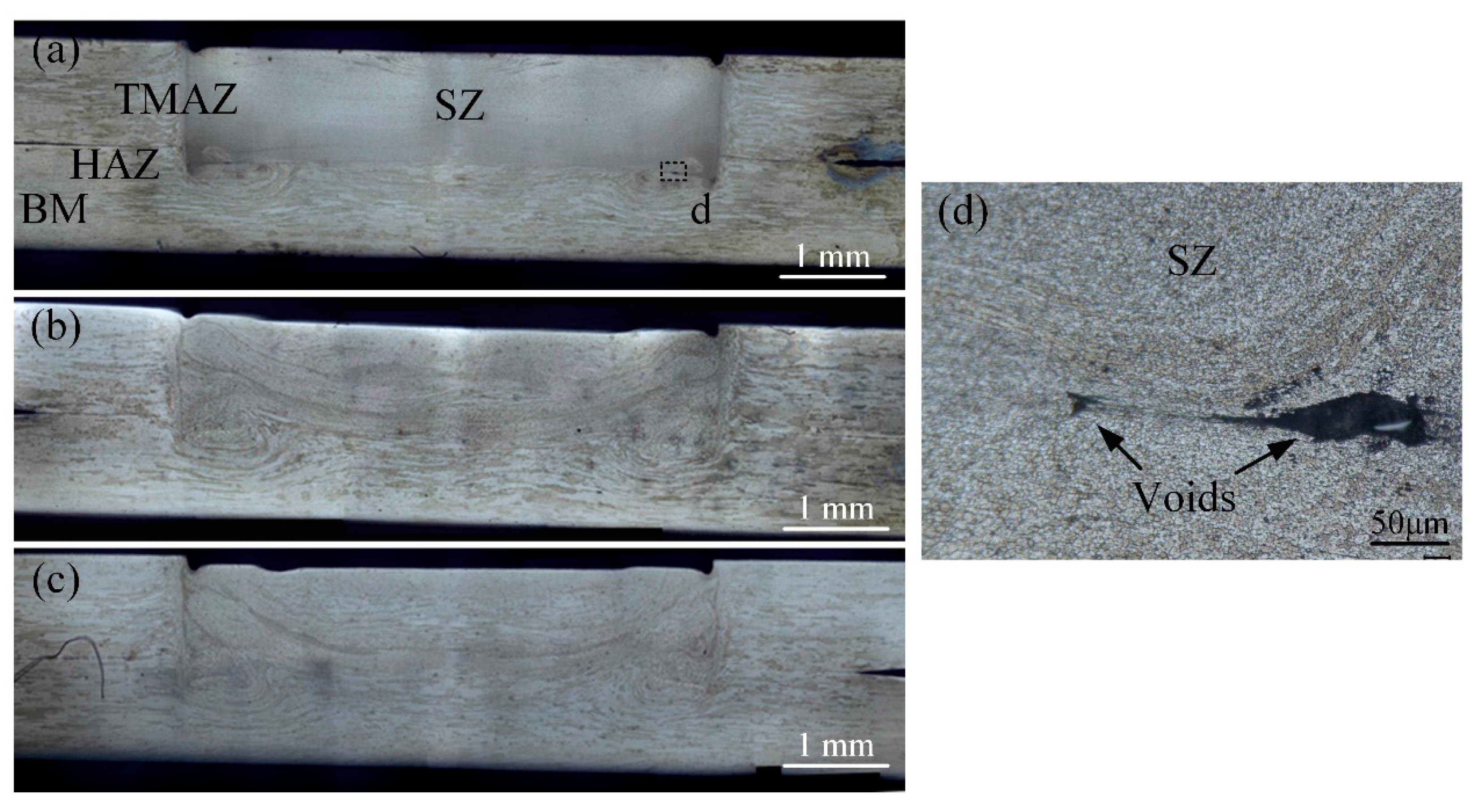
3.1. Cross-Sections of the Joints
3.2. Microstructure at Different Regions of the Joint
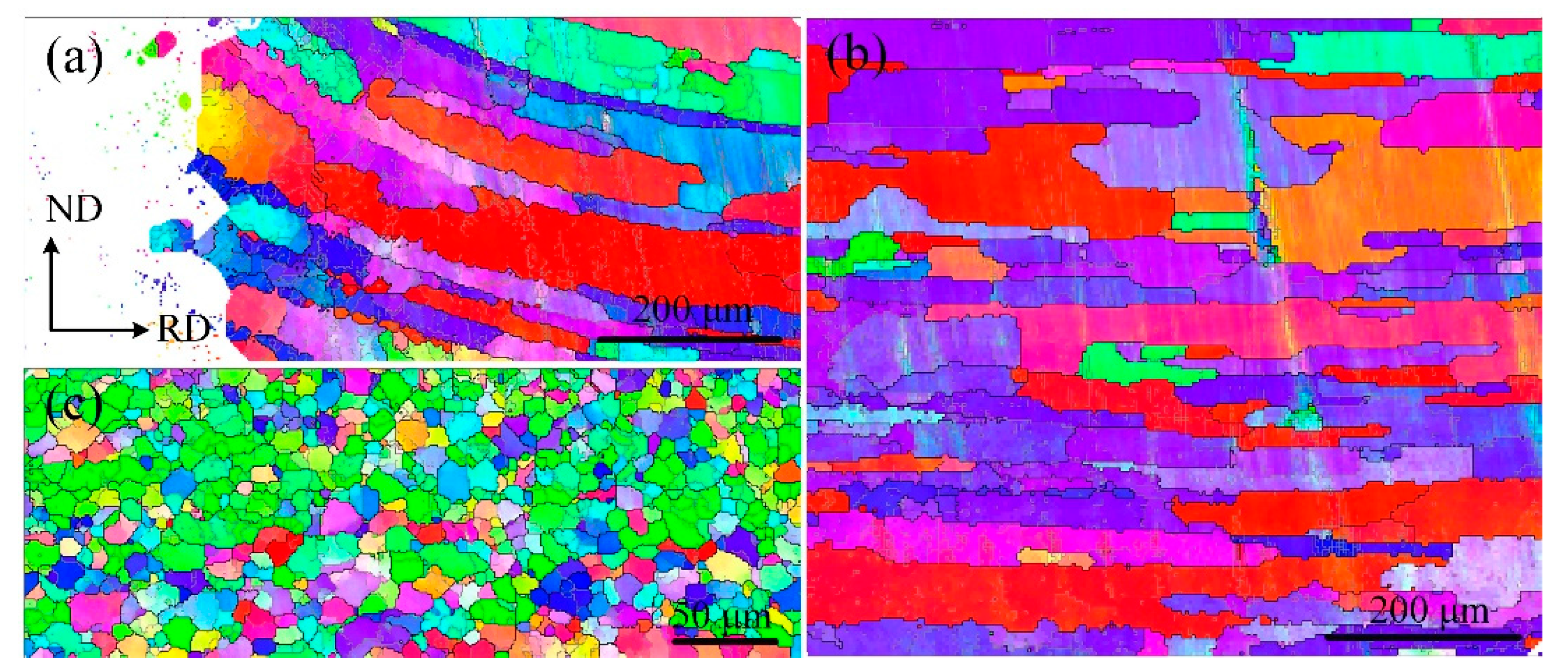
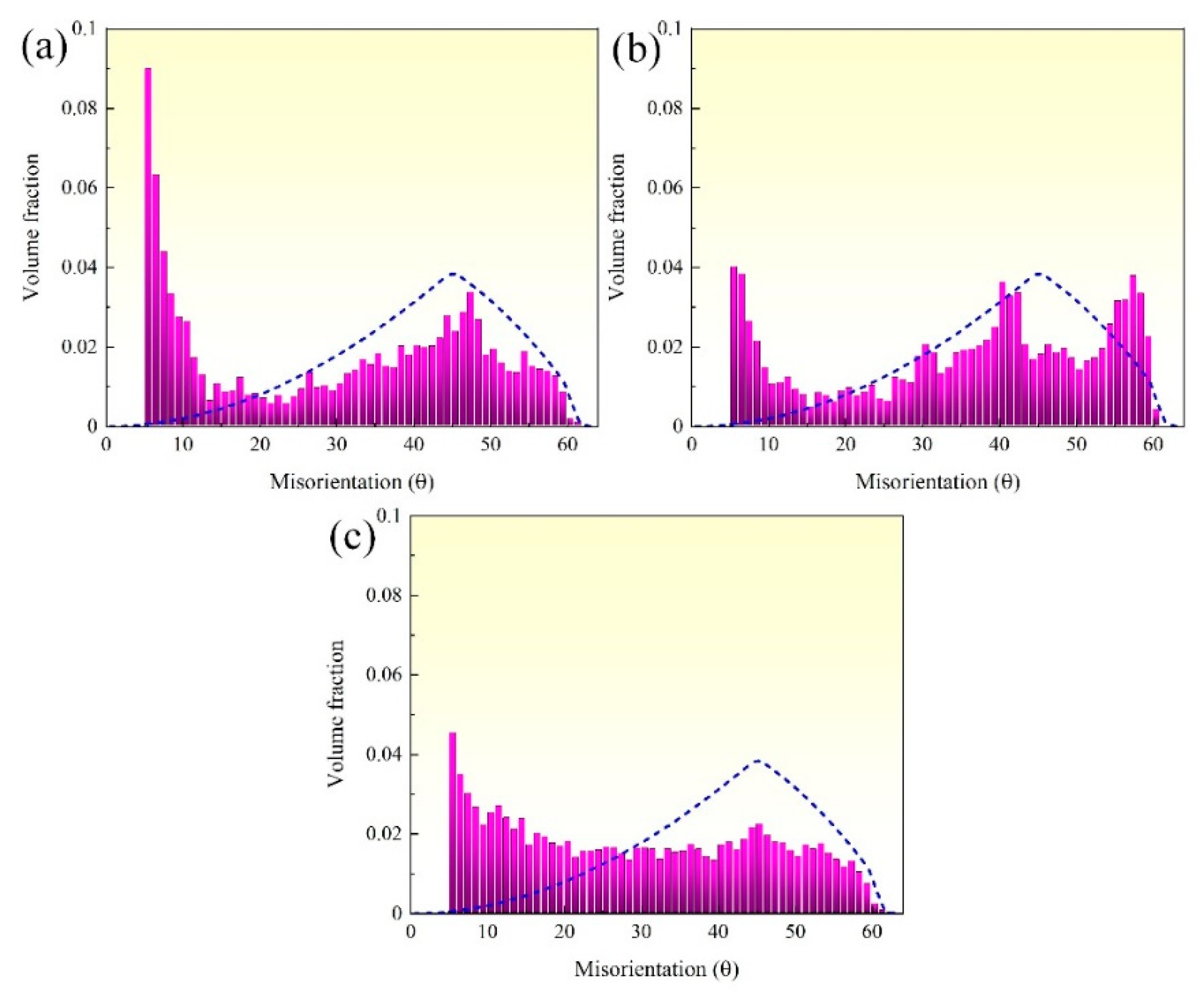
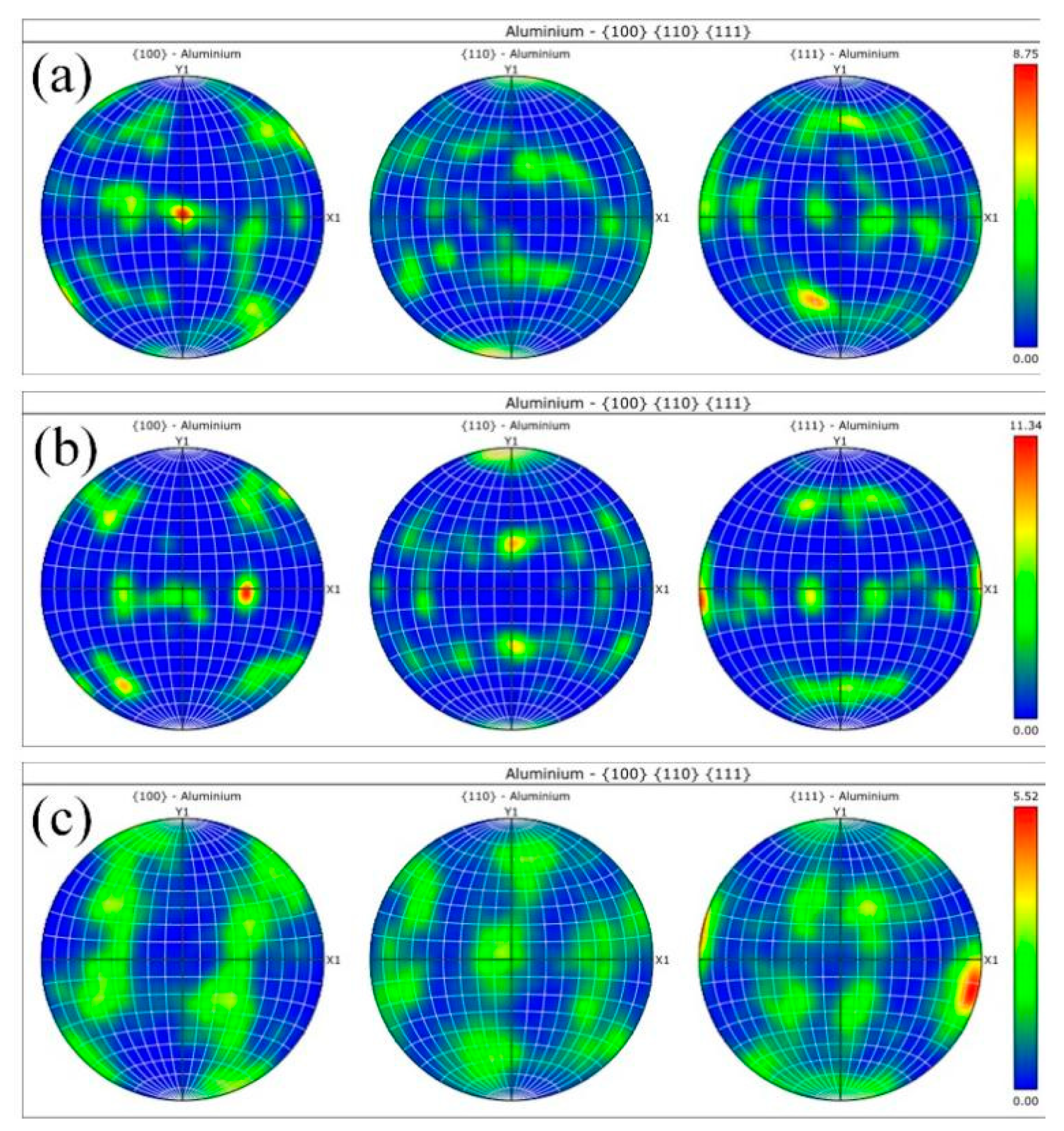
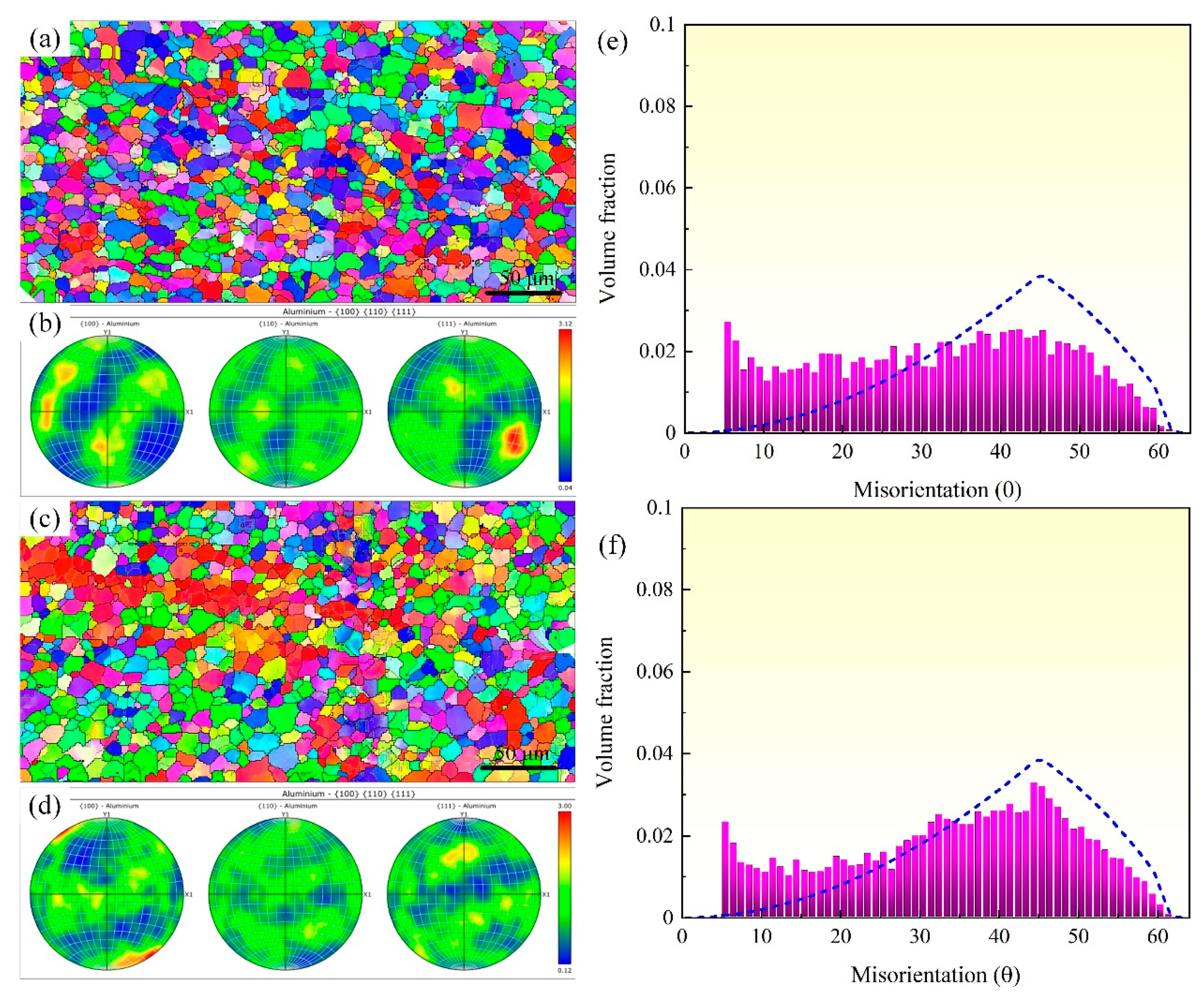
3.3. Effect of Rotating Speed on the Microstructure of the Joint
3.4. Effect of Welding Time on the Microstructure of the Joint
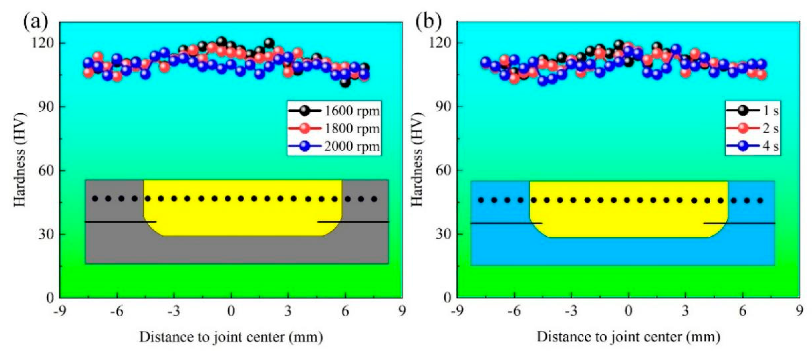
3.5. Hardness of the Joints
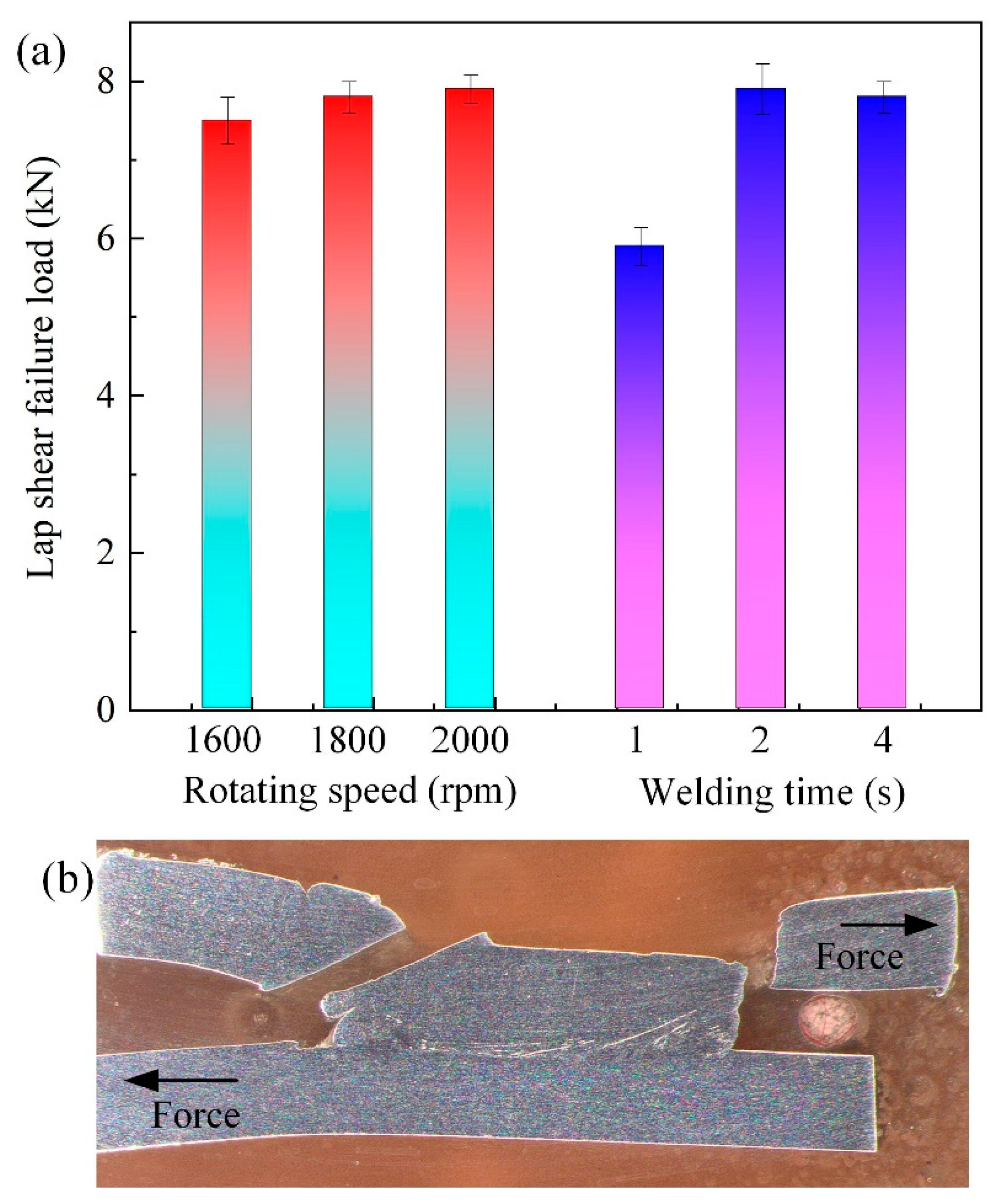
3.6. Tensile Properties of the Joints
4. Conclusions
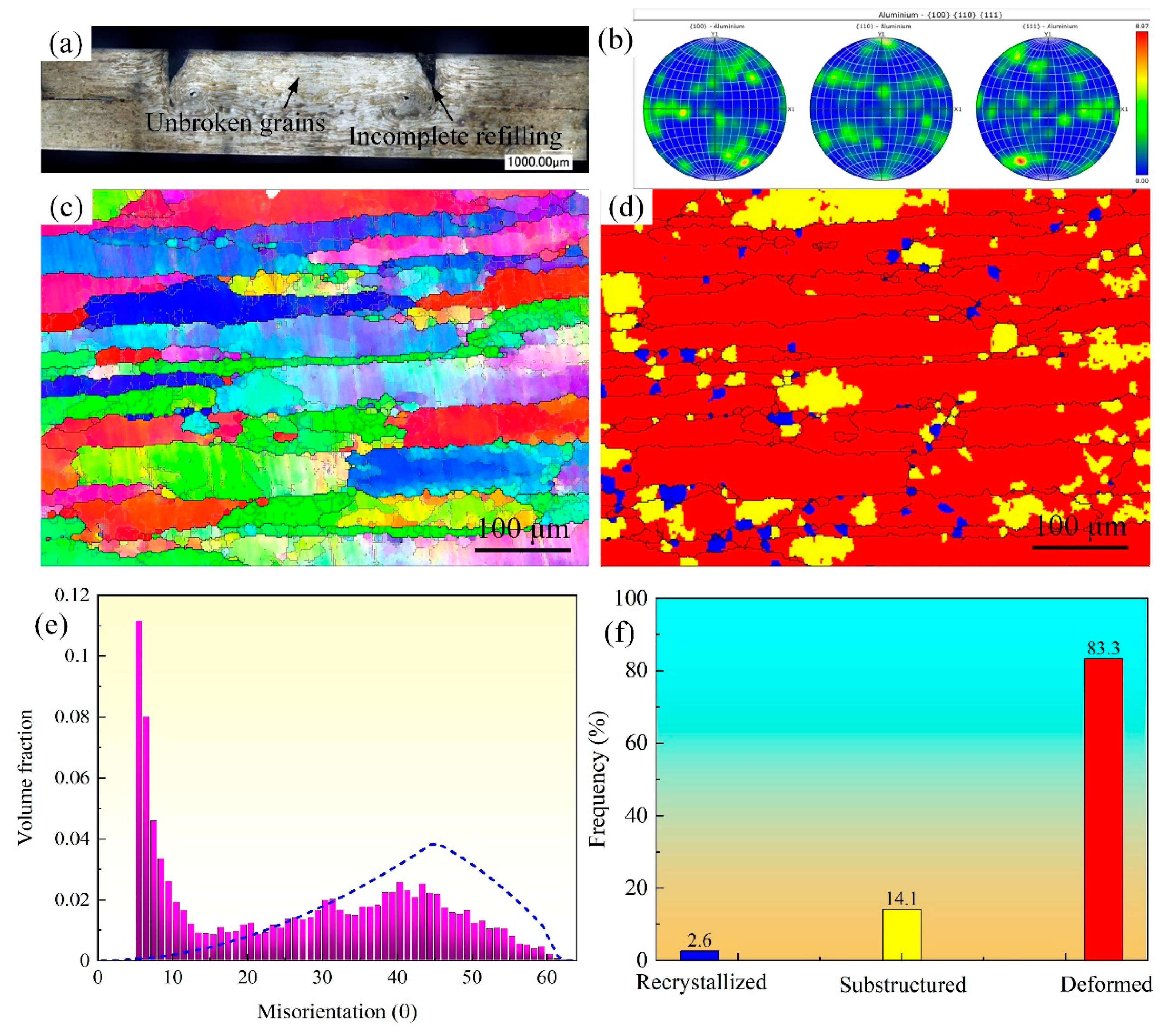
- The joints show similar morphologies with changing rotating speed. A tiny void is obtained when using a low rotating speed of 1600 rpm.
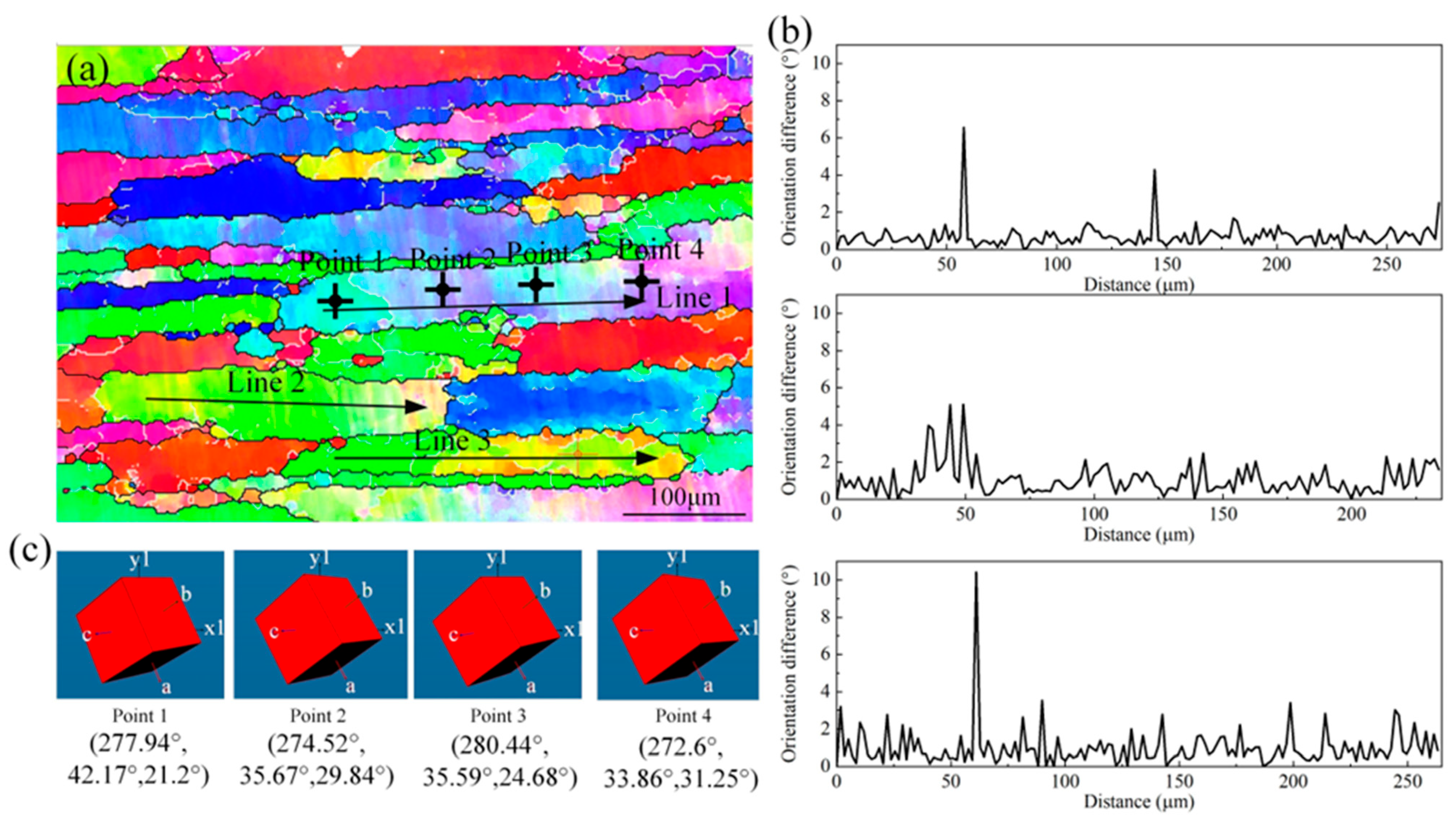
- Increasing the rotating speed causes the coarseness of the grains in the SZ due to the increased heat input. The grains in the SZ are not completely broken when using a short welding time of 1 s. Although not completely broken, the long grains in the SZ show different orientations in different regions inside one grain.
- Both a low rotating speed and a short welding time cause an increase in the hardness of the joint. Increasing the rotating speed results in a slight increase in the failure load of the joint. The failure strength of the joint first increases and then decreases with an increase in the welding time. A maximum failure load of 7.9 kN is obtained when using a welding time of 2 s.
Author Contributions
Funding
Data Availability Statement
Conflicts of Interest
References
- Wu, B.; Wang, Y.; Liu, X.; Zhang, D.; Zhou, S.; Deng, L.; Wang, L.; Li, H. Investigation on dynamic deformation behavior of 7A75 aluminum alloy over wide strain rates and constitutive model establishment. J. Mater. Res. Technol. 2024, 30, 5963–5976. [Google Scholar] [CrossRef]
- Lipińska, M.; Pixner, F.; Szachogłuchowicz, I.; Mittermayr, F.; Grengg, C.; Enzinger, N.; Lewandowska, M. Application of electron beam welding technique for joining coarse-grained and ultrafine-grained plates from Al-Mg-Si alloy. J. Manufact. Process. 2023, 104, 28–43. [Google Scholar] [CrossRef]
- Casalegno, V.; Smeacetto, F.; Salvo, M.; Sangermano, M.; Baino, F.; Noé, C.; Orlandi, M.; Piavani, R.; Bonfanti, R.; Ferraris, M. Study on the joining of ceramic matrix composites to an Al alloy for advanced brake systems. Ceram. Int. 2021, 47, 23463–23473. [Google Scholar] [CrossRef]
- Chen, D.; Zhan, X.; Liu, T.; Zhao, Y.; Qi, N.; Sun, L. Effect of porosity morphology and elements characteristics on mechanical property in T-joints during dual laser-beam bilateral synchronous welding of 2060/2099 Al-Li alloys. Opt. Laser. Technol. 2021, 140, 107019. [Google Scholar] [CrossRef]
- Zhou, X.; Zhao, H.; Liu, F.; Yang, B.; Xu, B.; Chen, B.; Tan, C. Effects of beam oscillation modes on microstructure and mechanical properties of laser welded 2060 Al-Li alloy joints. Opt. Laser. Technol. 2021, 144, 107389. [Google Scholar] [CrossRef]
- Li, Q.; You, G.; Ling, X.; Zhou, P.; Wang, L.; Feng, J.; Zeng, S.; Tong, X.; Jiang, B. Enhancing fusion welding in die-cast Mg alloys: A combined ultrasonic vibration and hot rolling approach for porosity reduction, microstructure refinement, and mechanical property improvement. J. Mater. Process. Technol. 2024, 331, 118513. [Google Scholar] [CrossRef]
- Lee, J.; Jang, J.; Lee, S.; Kang, M.; Lim, T.; Lee, S.H. Mitigating solidification cracking during the laser welding of extruded Al–Mg–Si alloys by tailoring the microstructure. Eng. Sci. Technol. 2024, 55, 101759. [Google Scholar] [CrossRef]
- Xu, Z.; Li, Z.; Ji, S.; Zhang, L. Refill friction stir spot welding of 5083-O aluminum alloy. J. Mater. Sci. Technol. 2018, 34, 878–885. [Google Scholar] [CrossRef]
- Song, Q.; Han, Z.; Hu, Y.; Wang, D.; Ren, Z.; Zhou, J.; Zhang, Z.; Zhao, H. Investigations on mechanical and surface properties of friction stir welded dissimilar joints of 2507 SDSS and 317L ASS. Tribol. Int. 2024, 201, 110226. [Google Scholar] [CrossRef]
- Xue, W.; Song, N.; Li, J.; Huang, C.; He, D.; Ren, X. Improving mechanical properties of 18 mm thick plate friction stir welding joint by combining the thermomechanical-fluid coupled model and partial least squares regression algorithm. J. Manuf. Process. 2024, 126, 443–470. [Google Scholar] [CrossRef]
- Anandan, B.; Manikandan, M. Machine learning approach for predicting the peak temperature of dissimilar AA7050-AA2014A friction stir welding butt joint using various regression models. Mater. Lett. 2022, 325, 132879. [Google Scholar] [CrossRef]
- Tiwari, S.; Verma, S.; Kaushik, P. Investigating the influence of stress ratio variation on the crack growth rate in friction stir welded dissimilar aluminum alloys. Eng. Fail. Anal. 2024, 165, 108828. [Google Scholar] [CrossRef]
- Fan, W.; Yang, X.; Chu, Q.; Li, W. An efficient synergistic double-sided friction stir spot welding method: A case study on process optimization, interfacial characteristics and mechanical properties of 2198-T8 aluminum-lithium alloy joints. J. Manuf. Process. 2024, 131, 213–232. [Google Scholar] [CrossRef]
- Tang, Y.; Li, W.; Zou, Y.; Wang, W.; Xu, Y.; Vairis, A.; Çam, G. Effects of tool rotation direction on microstructure and mechanical properties of 6061 aluminum alloy joints by the synergistically double-sided friction stir welding. J. Manuf. Process. 2024, 126, 109–123. [Google Scholar] [CrossRef]
- Tier, M.D.; Rosendo, T.S.; Santos, J.F.D.; Huber, N.; Mazzaferro, J.A.; Mazzaferro, C.P.; Strohaecker, T.R. The influence of refill FSSW parameters on the microstructure and shear strength of 5042 aluminium welds. J. Mater. Process. Technol. 2013, 213, 997–1005. [Google Scholar] [CrossRef]
- Cao, Y.; Zhang, C.C.; Xing, Y.F.; Wang, M. Pin plunging reinforced refill friction stir spot welding of Alclad 2219 to 7075 alloy. J. Mater. Process. Technol. 2020, 284, 116760. [Google Scholar] [CrossRef]
- Han, B.; Huang, Y.; Lv, S.; Wan, L.; Feng, J.; Fu, G. AA7075 bit for repairing AA2219 keyhole by filling friction stir welding. Mater. Des. 2013, 51, 25–33. [Google Scholar] [CrossRef]
- Sharma, A.; Khan, Z.A.; Siddiquee, A.N. Review of various methods of keyhole removal in friction stir welding sheets and pipes. Mater. Today Proc. 2022, 62, 404–409. [Google Scholar] [CrossRef]
- Shen, Z.; Li, W.Y.; Ding, Y.; Hou, W.; Liu, X.C.; Guo, W.; Chen, H.Y.; Liu, X.; Yang, J.; Gerlich, A.P. Material flow during refill friction stir spot welded dissimilar Al alloys using a grooved tool. J. Manufact. Process. 2020, 49, 260–270. [Google Scholar] [CrossRef]
- Li, Y.; Sun, G.; Zhang, Z.; Zhou, L.; Guo, N.; Meng, Q.; Dong, J.; Zhao, H. Texture evolution of refill friction stir spot welding in alclad 2A12-T42 aluminum alloy. Mater. Charact. 2023, 205, 113289. [Google Scholar] [CrossRef]
- Shen, Z.; Ding, Y.; Gopkalo, O.; Diak, B.; Gerlich, A.P. Effects of tool design on the microstructure and mechanical properties of refill friction stir spot welding of dissimilar Al alloys. J. Mater. Process. Technol. 2018, 252, 751–759. [Google Scholar] [CrossRef]
- Fritsche, S.; Draper, J.; Toumpis, A.; Galloway, A.; Amancio-Filho, S.T. Refill friction stir spot welding of AlSi10Mg alloy produced by laser powder bed fusion to wrought AA7075-T6 alloy. Manuf. Lett. 2022, 34, 78–81. [Google Scholar] [CrossRef]
- de Castro, C.C.; Shen, J.; Plaine, A.H.; Suhuddin, U.F.H.; de Alcântara, N.G.; Santos, J.F.D.; Klusemann, B. Tool wear mechanisms and effects on refill friction stir spot welding of AA2198-T8 sheets. J. Mater. Res. Technol. 2022, 20, 857–866. [Google Scholar] [CrossRef]
- Ferrari, V.R.; Coury, F.G.; Suhuddin, U.F.H.; Alcântara, N.G.; Santos, J.F.D.; Ohashi, R.; Fujimoto, M.; Koga, G.Y. Effects of semi-solid structure on interface formation of dissimilar aluminum to galvanized steel welds produced by load-controlled refill friction stir spot welding. J. Manufact. Process. 2022, 84, 298–315. [Google Scholar] [CrossRef]
- Fu, B.; Shen, J.; Suhuddin, U.F.H.R.; Chen, T.; Santos, J.F.D.; Klusemann, B.; Rethmeier, M. Improved mechanical properties of cast Mg alloy welds via texture weakening by differential rotation refill friction stir spot welding. Scripta. Mater. 2021, 203, 114113. [Google Scholar] [CrossRef]
- Fu, B.; Shen, J.; Suhuddin, U.F.H.R.; Pereira, A.A.C.; Maawad, E.; dos Santos, J.F.; Klusemann, B.; Rethmeier, M. Revealing joining mechanism in refill friction stir spot welding of AZ31 magnesium alloy to galvanized DP600 steel. Mater. Des. 2021, 209, 109997. [Google Scholar] [CrossRef]
- Yu, M.; Zhao, H.; Zhang, Z.; Zhou, L.; Song, X. Friction surfacing assisted refilled friction stir spot welding of AA6061 alloy and Q235 steel. J. Manuf. Process. 2022, 77, 1–12. [Google Scholar] [CrossRef]
- Wang, S.; Wei, X.; Xu, J.; Hong, J.; Song, X.; Yu, C.; Chen, J.; Chen, X.; Lu, H. Strengthening and toughening mechanisms in refilled friction stir spot welding of AA2014 aluminum alloy reinforced by graphene nanosheets. Mater. Des. 2020, 186, 108212. [Google Scholar] [CrossRef]


| Alloy | Cu | Li | Fe | Mn | Mg | Zn | Si | Ag | Al |
|---|---|---|---|---|---|---|---|---|---|
| 2060 | 3.56 | 0.72 | 0.026 | 0.3 | 0.72 | 0.34 | 0.025 | 0.086 | Bal. |
Disclaimer/Publisher’s Note: The statements, opinions and data contained in all publications are solely those of the individual author(s) and contributor(s) and not of MDPI and/or the editor(s). MDPI and/or the editor(s) disclaim responsibility for any injury to people or property resulting from any ideas, methods, instructions or products referred to in the content. |
© 2024 by the authors. Licensee MDPI, Basel, Switzerland. This article is an open access article distributed under the terms and conditions of the Creative Commons Attribution (CC BY) license (https://creativecommons.org/licenses/by/4.0/).
Share and Cite
Cui, Y.; Wang, B.; Dong, W.; Li, Z.; Yan, J. Refill Friction Stir Spot Welding of an Al-Li Alloy: The Effects of Rotating Speed and Welding Time on Joint Microstructure and Mechanical Properties. Metals 2024, 14, 1383. https://doi.org/10.3390/met14121383
Cui Y, Wang B, Dong W, Li Z, Yan J. Refill Friction Stir Spot Welding of an Al-Li Alloy: The Effects of Rotating Speed and Welding Time on Joint Microstructure and Mechanical Properties. Metals. 2024; 14(12):1383. https://doi.org/10.3390/met14121383
Chicago/Turabian StyleCui, Yuanbiao, Binbin Wang, Wenzhe Dong, Zhengwei Li, and Jiuchun Yan. 2024. "Refill Friction Stir Spot Welding of an Al-Li Alloy: The Effects of Rotating Speed and Welding Time on Joint Microstructure and Mechanical Properties" Metals 14, no. 12: 1383. https://doi.org/10.3390/met14121383
APA StyleCui, Y., Wang, B., Dong, W., Li, Z., & Yan, J. (2024). Refill Friction Stir Spot Welding of an Al-Li Alloy: The Effects of Rotating Speed and Welding Time on Joint Microstructure and Mechanical Properties. Metals, 14(12), 1383. https://doi.org/10.3390/met14121383