Article

Innovative Solid-State Recycling of Aluminum Alloy AA6063 Chips Through Direct Hot Rolling Process

by
Mauro Carta
1,*,
Noomane Ben Khalifa
2,3,
Pasquale Buonadonna
1,
Rayane El Mohtadi
1,
Filippo Bertolino
1 and
Mohamad El Mehtedi
1
1
Department of Mechanical, Chemical and Materials Engineering, University of Cagliari, 09123 Cagliari, Italy
2
Institute for Production Technology and Systems, Leuphana University Lüneburg, 21335 Lüneburg, Germany
3
Institute of Material and Process Design, Helmholtz-Zentrum Hereon, 21502 Geesthacht, Germany
*
Author to whom correspondence should be addressed.
Metals 2024, 14(12), 1442; https://doi.org/10.3390/met14121442
Submission received: 11 November 2024 / Revised: 12 December 2024 / Accepted: 13 December 2024 / Published: 17 December 2024
(This article belongs to the Special Issue Sustainability Approaches in the Recycling of Light Alloys)

Abstract

:
In this paper, the feasibility of an innovative solid-state recycling process for aluminum alloy AA6063 chips through direct rolling is studied, with the aim of offering an environmentally sustainable alternative to conventional recycling processes. Aluminum chips, produced by milling an AA6063 billet without the use of lubricants, were first compacted using a hydraulic press with a 200 kN load and subsequently heat-treated at 570 °C for 6 h. The compacted chips were directly hot-rolled through several successive passes at 490 °C. The bulk material underwent the same rolling schedule to allow comparison of the samples and assess the process, in terms of mechanical properties and microstructure. All the rolled samples were tested by tensile and microhardness tests, whereas the microstructure was observed by an optical microscope and the EBSD-SEM technique. The fracture surface of all tested samples was analyzed by SEM. Recycled samples exhibited good mechanical properties, comparable to those of the bulk material. In particular, the bulk material showed an ultimate tensile strength of 218 MPa, in contrast to 177 MPa for the recycled chips, and comparable elongation at break. This study demonstrates that direct rolling of compacted aluminum chips is both technically feasible and has environmental benefits, offering a promising approach for sustainable aluminum recycling in industrial applications within a circular economy framework.

1. Introduction

Aluminum is extensively utilized across diverse industries due to its lightweight, corrosion resistance, and excellent mechanical properties [1].
The extraction of aluminum from its raw material, bauxite ore, requires significant energy input through processes like the Bayer and Hall–Héroult processes, resulting in substantial carbon dioxide emissions [2]. In fact, primary aluminum production is estimated to be responsible for approximately 1% of the world’s total greenhouse gas emissions [3]. The primary production of aluminum represents a significant environmental challenge due to the high level of energy consumption and emissions associated with the Bayer and Hall–Héroult processes, mining exploitation, and waste release, in particular red mud [4,5,6]. Furthermore, bauxite mining contributes to deforestation, biodiversity loss, and disruption of local ecosystems.
The widespread use of aluminum underscores the critical need for efficient recycling methods to conserve primary resources and reduce environmental impacts.
Aluminum recycling serves as a sustainable alternative that significantly reduces the environmental impact associated with primary production. Recycling aluminum saves up to 95% [6] of the energy required for producing aluminum from raw materials, leading to greenhouse gas emissions of just 5% of the primary process [7].
Melting techniques have historically dominated the recycling of aluminum. While they are quite efficient at recovering the metal, they are energy-intensive and frequently result in substantial material loss due to oxidation and dross development. Aluminum scrap is processed in several steps, including scrap collection and sorting, contamination removal, furnace melting, and ingot casting. This method effectively recycles large quantities of aluminum, but it consumes considerable energy, primarily in the melting and holding operations. Furthermore, the melting process releases greenhouse gases and other pollutants, contributing to environmental degradation. Cleaner energy sources and advanced filtration technologies are two ways to mitigate these effects, but they come with additional operational costs and technological challenges.
In response to the limitations of conventional recycling, several alternative methods have been explored, called solid-state recycling (SSR) processes. Among them, the mechanical processes that require plastic deformation are quite effective and because they can be implemented at lower temperatures, the overall environmental footprint is reduced [8]. This kind of process is often used for the recycling of chips, since chip production is required in a lot of industries where machining is a step to obtain the final mechanical parts. Conventional chip recycling through melting may not be convenient due to its elevated metal loss (up to 46%), imputable to its oxidation, and high surface-to-volume ratio, which depends on the method of introducing the chips [9].
Although there are many different processes, depending on the process, they often include phases like comminution, cleaning, drying, cold compaction of chips, and subsequent plastic deformation [10]. Some examples of these processes include direct extrusion [11,12], friction stir extrusion (FSE) [13,14,15], friction stir consolidation (FSC) [16,17], equal-channel angular pressing (ECAP) [18,19], Spark Plasma Sintering [20,21], and other processes. However, most of the SSR methods are still at the laboratory scale and often produce materials with inferior properties due to contamination and the inability to fully recover aluminum from mixed scrap. Even chip morphology can affect the results of these kind of recycling processes [22]. Additionally, these methods involve complex processes that are difficult to scale up to an industrial level. Even so, some attempts to scale the production to an industrial scale have been made by Paraskevas et al. [23] using a porthole die hot extrusion. The KOBO method is a variation of direct extrusion that incorporates cyclic oscillations of the die to enhance material properties and shows potential for solid-state recycling of chips [24]. Several authors studied miscellaneous methods that include hot or cold rolling as an additional step in the process to produce sheets. Suzuki et al. [25] produced rolled products by hot rolling as a second step of the SSR process, after chip extrusion. Chiba et al. [26] explore instead the possibility of recycling chips through cold extrusion and consequently cold rolling. Allwood et al. [27] studied the possibility of cold bonding through forging, rolling, or extrusion processes, performed separately, demonstrating that bonding could occur with sufficient strain, but some voids remained, while Kore et al. [28] studied the possibility of hot rolling as a recycling route for chips of AA6082. Since there is a lack of contributions in the literature, to the author’s best knowledge, that have studied rolling as an SSR technique, the innovation and purpose of this work is to apply Direct Hot Rolling to compacted chips of aluminum alloys, without the usage of any previous process excluding cold compaction. A solid-state recycling process based on rolling could be crucial in the industrial field, since rolling is one of the most important and widespread manufacturing processes. Particularly important would be the development of a procedure that can be directly applied to existing industrial rolling plants, with little or no alterations. This research not only addresses the immediate needs of the aluminum recycling sector but also aligns with global sustainability goals aimed at reducing industrial emissions and conserving natural resources [29,30].
In this paper, a new solid-state recycling technique called Direct Hot Rolling (DHR) is introduced. This article discusses the feasibility of the DHR process, focusing on the mechanical and microstructural properties of the recycled aluminum relative to the original bulk material. Assessing DHR’s viability as an AA6063 chip recycling technique is the goal of this study.

2. Materials and Methods

The recycling process of Direct Hot Rolling (DHR) involves several key steps [31]. First, aluminum chips are compacted under high pressure to form a semi-coherent mass. These compacted chips are then heat-treated before rolling. The heat-treated compacted billets undergo successive rolling passes at elevated temperatures to achieve the desired thickness and bonding. The recycled samples were analyzed and compared with bulk material that was rolled according to the same thermo-mechanical schedule, focusing on their mechanical properties and microstructure. Figure 1 schematically illustrates the experimental procedure along with all the characterization techniques used. In the following paragraphs, these steps will be described in detail.

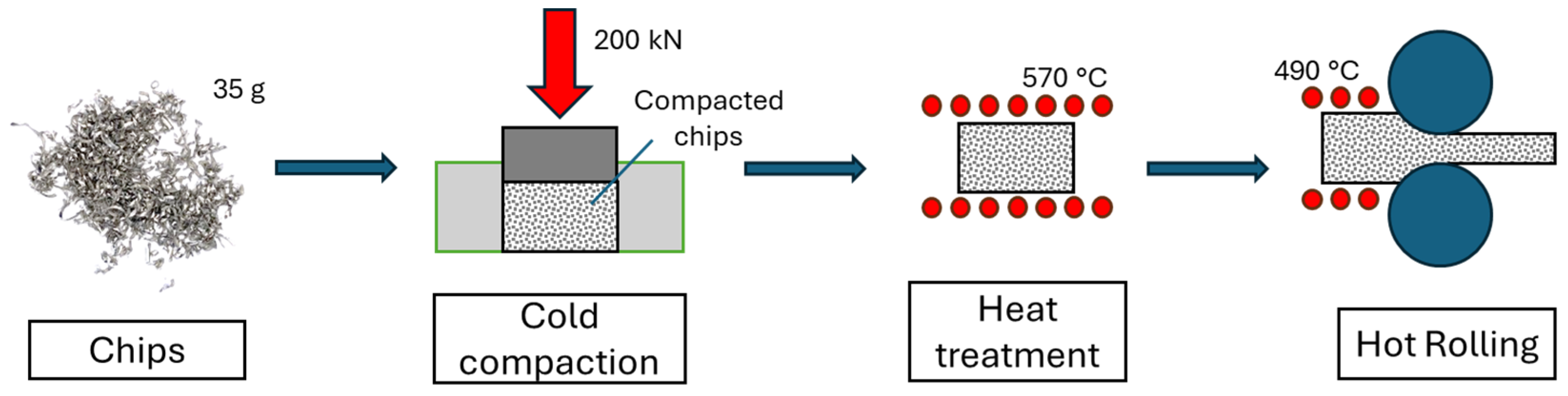
2.1. Chip Production and Cold Compaction

The chips used in this study were produced by a machining process without the use of lubricants to avoid any contamination, by milling a billet of AA6063 manufactured by Hydro Spa (Norsk Hydro, Oslo, Norway). The mean dimensions of the chips are 1.1 mm in width and 25 ± 20 mm in length. The nominal chemical composition is reported in Table 1. This material was chosen because the AlMgSi family of aluminum alloys are widely used in a lot of field and applications, with high production of chips as waste material, and even in the automotive industry [32]. The as-received material is characterized by a 186 MPa ultimate tensile strength (UTS) and 22% elongation to rupture. The shape of the machined chips is shown in Figure 2a.
The first step in the recycling process is cold compaction. Thus, 35 g of chips were compacted using a hydraulic press with an applied load of 200 kN using the die shown in Figure 2b, resulting in billets with dimensions of 30 × 60 × 10.5 mm3 and achieving a density of approximately 68% of the bulk material (Figure 2a).

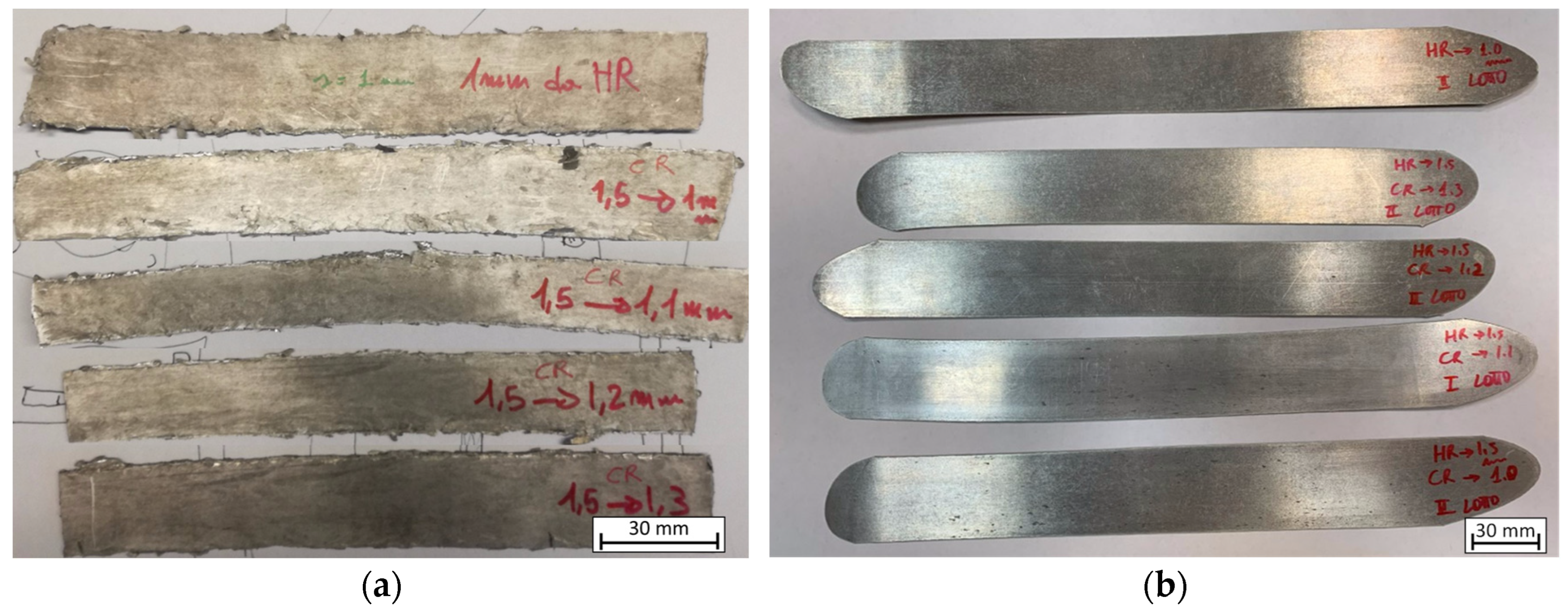
2.2. Heat Treatment and Direct Hot Rolling Process

All samples were annealed at 570 °C for 6 h in a muffle furnace (air atmosphere) (Nabertherm, Lilienthal, Germany), and then hot rolled (HR) at 490 °C through several consecutive passes without using any lubricant. These temperatures were selected based on those commonly employed in the industrial setting for the secondary recycling production of AA6063.
The rolling machine is a two-high rolling mill “BW200” manufactured by Carl Wezel (Carl Wezel, Mühlacker, Germany), characterized by a 130 mm roll diameter and a constant rotational speed of 52 rpm. Compacted chips and bulk material underwent the same rolling passes as reported in Table 2. In order to restore the initial temperature of 490 °C after each rolling pass, the samples were returned to the furnace to recover the temperature. Figure 3 shows a schematic overview of the process. After the 7th pass (1.5 mm of thickness), the samples underwent different last rolling passes. In particular, the final cold rolling (CR) pass was carried out with different values of 1.3, 1.2, 1.1, and 1.0 mm to reach the final desired thicknesses (Figure 4), or a hot rolling (HR) pass was performed directly down to a 1.0 mm final thickness, for a total of 5 different rolling schedules, for both recycled chips and bulk, and a total of 10 conditions. After the last rolling pass, all samples were immediately water-quenched and conserved at −20 °C in order to avoid the onset of natural aging. Table 2 reports the nominal thickness after every pass.
The jagged borders of the sample shown in Figure 4a were cut and could be considered as scrap of the process, which needed to be recycled again using the same process.

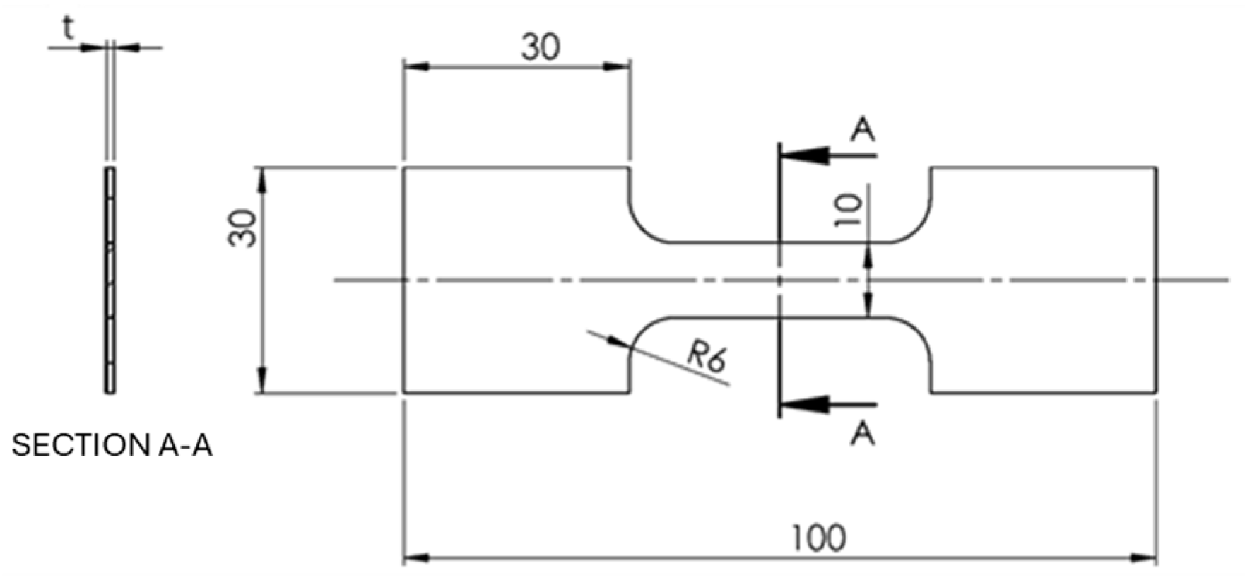
2.3. Mechanical Properties

Mechanical properties were investigated for every condition, for both bulk material and recycled chips, and measured in the as-rolled condition. Tensile tests and Vickers microhardness tests were carried out to assess the mechanical properties. Samples were milled with the geometry shown in Figure 5 according to ASTM E8/E8M and BS EN 895 [33,34]. The tensile tests were carried out with a material testing machine (Galdabini® SUN500, Cardano al Campo, Italy). Three replications were performed for each condition.
Vickers microhardness was measured with a Shimadzu Microhardness Tester type M (Shimadzu Corporation, Kyoto, Japan), with a load of 200 gf, for each condition along the rolling thickness section.

2.4. Microstructure Analysis

The microstructure evolution of the rolled samples was analyzed by an optical microscope and SEM/EBSD. Samples were prepared for optical analysis by cutting them along the rolling directions, electropolishing them with H3PO4 at 70% at 75 °C, and then etching them with Barker’s reagent (HBF4 at 5%). Micrographs were obtained for both recycled chips and bulk samples under polarized light with the usage of an optical microscope Leica Z8 Wild M420 (Leica Microsystems, Amsterdam, The Netherlands).
SEM samples were cut along the rolling direction and mechanically polished. For EBSD analysis, the samples were further electropolished to remove the deformation layer and scratches. The electropolishing process was conducted using a Struers Lectropol-5 and Struers AC2 electrolyte, applying 20 V for 20 s. The SEM/EBSD evaluation was carried out on a FEG-SEM Zeiss Ultra 55 Gemini (Carl Zeiss, Oberkochen, Germany) equipped with an EDAX Hikari-Camera for EBSD (EDAX, Mahwah, NJ, USA) and two EDS detectors: SiLi and Apollo-SDD (EDAX, Mahwah, NJ, USA). The dimensions of the EBSD maps are 250 × 300 μm with a step of 0.4 µm, providing a detailed spatial resolution that captures the intricacies of the material’s microstructure across a substantial area.

3. Results and Discussions

AA6063 is a magnesium–silicon-precipitation-strengthened heat-treatable aluminum alloy obtained by aging heat treatment, with the hardening precipitate being Mg2Si.
The results are discussed in detail in the following paragraphs.

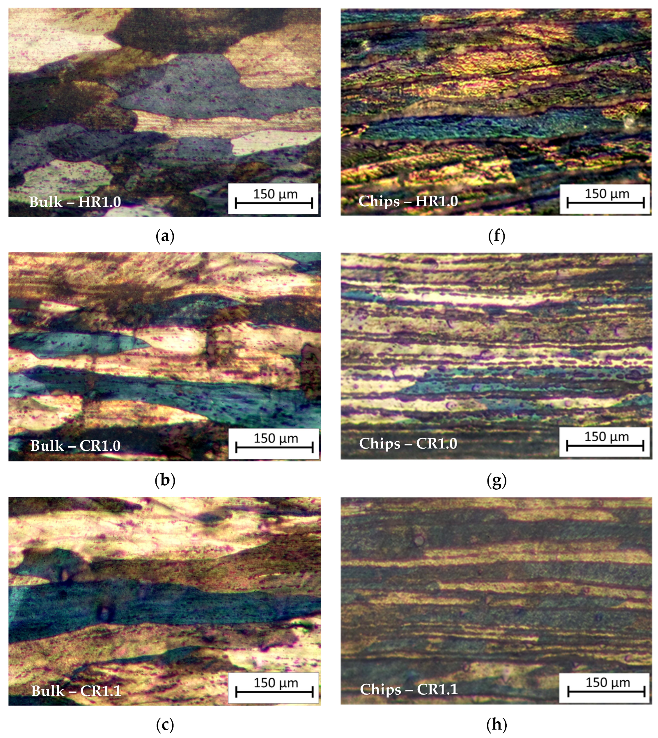
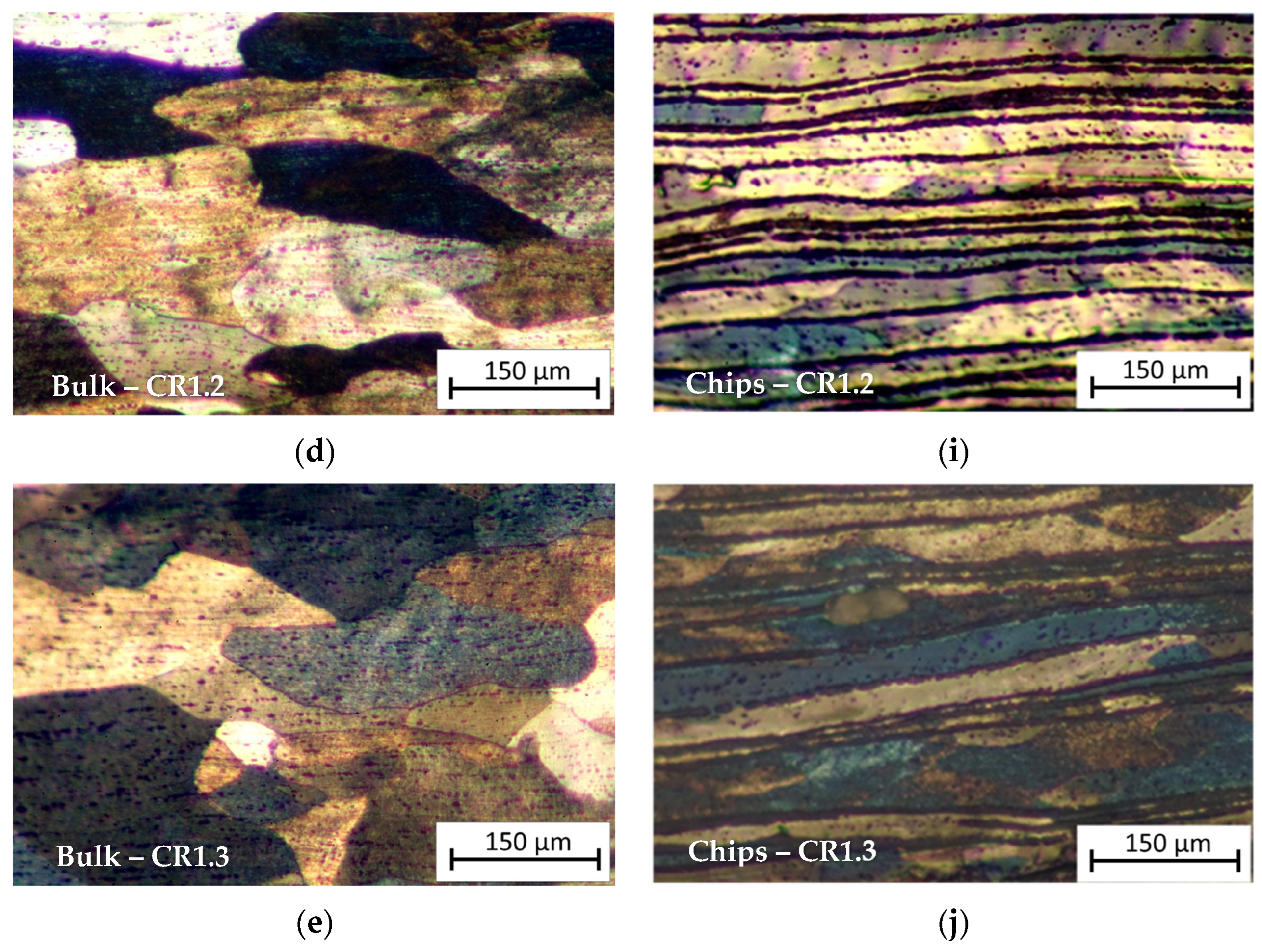
3.1. Metallographic Analysis

The micrographs in Figure 6 show a comparison between the optical microstructure of the bulk and recycled chip samples for all the rolling schedules.
As can be seen from Figure 6a–e, relative to the bulk samples, long elongated grains are visible in CR1.0 and CR1.1 conditions, while they are less evident in the CR1.2 and CR1.3 samples due to the low reduction rate. HR1.0 shows slightly elongated grains in the RD for the bulk sample, whereas in the recycled sample, the HR1.0 sample (hot-rolled until 1.0 mm thickness), the microstructure appears very layered; this is due to the prior cold compaction and subsequent plastic deformation by hot rolling of the chips. Comparing HR1.0 with the CR1.0 condition (Figure 6f,g), cold-rolled from 1.5 mm to 1.0 mm thickness, it can be observed that cold rolling provided a very layered structure with distinct bands with a lower thickness than in the HR condition. The micrographs show the presence of several chips layers, which appear separated by thick oxide films; elongated crystalline grains result that are decorated by these particles. Comparing the metallography of the chip cold-rolled samples, from the CR1.3 condition to CR1.0, it can be observed that increasing cold rolling in the last step results in a higher density of metal layers due to the reduction in the cross-sectional area of the individual layers.
Bulk HR1.0 and Chips HR1.0 (Figure 6a,f) illustrate the microstructural differences between bulk material and chips after hot rolling to a thickness of 1.0 mm. The bulk material displays more homogeneity, while the chip-derived material shows more heterogeneity and layering due to the prior machining process and inherent material inconsistencies like oxidized surfaces.
Bulk CR1.0 and Chips CR1.0 (Figure 6b,g): Both bulk and recycled samples, cold-rolled to 1.0 mm, exhibit significant strain alignment. The bulk sample displays a highly aligned, elongated microstructure along the rolling direction, typical of plastic deformation. Conversely, the recycled chips retain a more layered structure with visible striations from original chip boundaries. Potential oxide layers within these chips may hinder recrystallization and grain growth.
The micrographs illustrate how the initial material state—bulk or chips—significantly impacts the post-processing microstructure. Homogeneous bulk materials deform uniformly, exhibiting classic metal flow and structure development. Conversely, recycled chips, due to initial discontinuities, show a final layered microstructure in all samples, although with varying degrees of layer thickness.

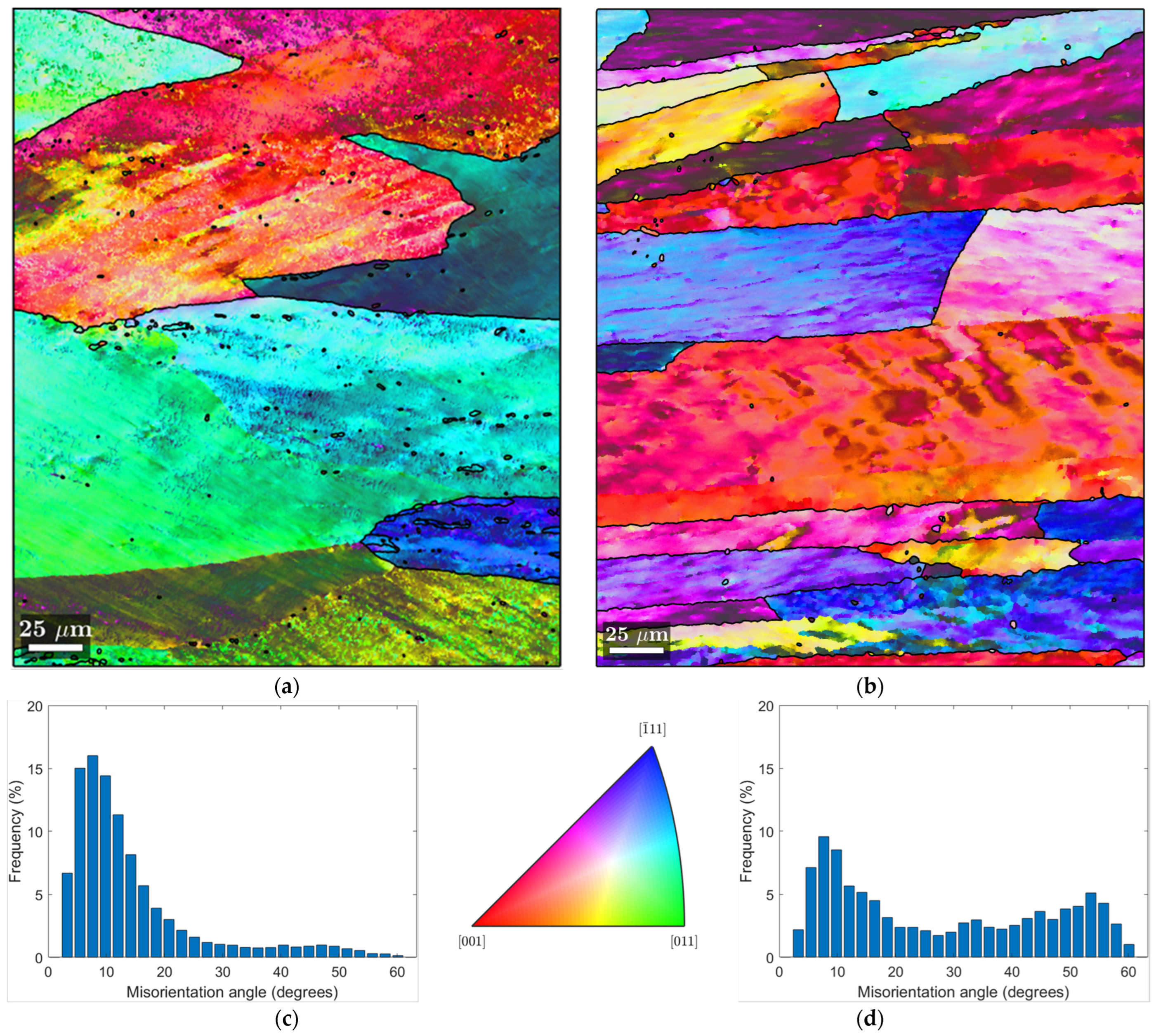
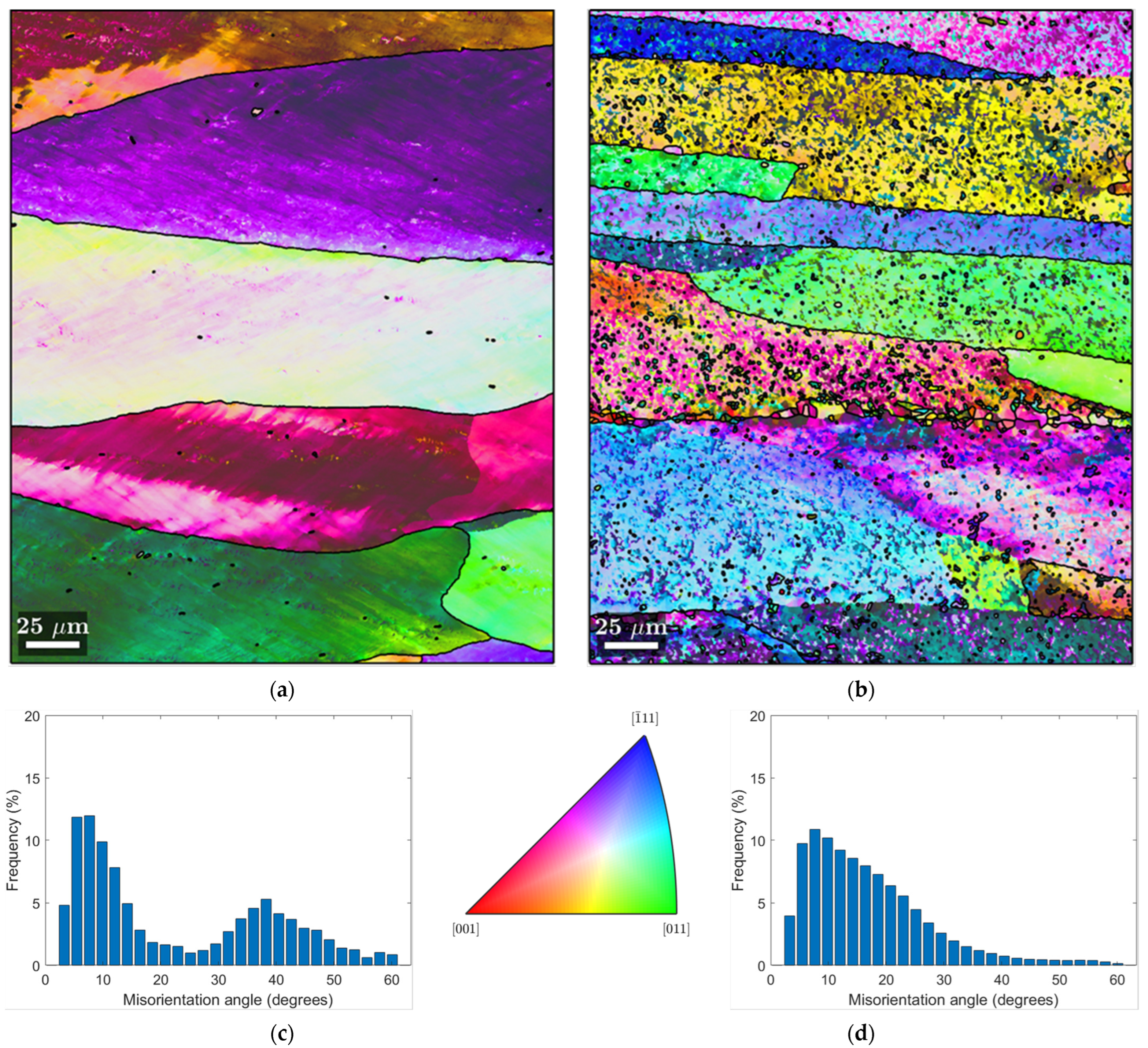
3.2. EBSD-SEM Analysis

MATLAB and the MTEX toolbox [35,36] were employed to facilitate the comprehensive analysis and visualization of the EBSD data. Inverse Pole Figure (IPF) maps and pole figures were generated to provide visual insight into the crystallographic orientation and texture of the materials.
Figure 7 and Figure 8 show IPF maps from EBSD measurements of both bulk and chip samples in the CR1.0 and HR1.0 conditions, respectively. The histogram of misorientation angles excludes angles below 3°, which is considered as an accuracy limit of this technique.
In the Inverse Pole Figure (IPF) maps, the grain boundaries are distinctly marked by black lines with a misorientation angle θ > 12°. High-angle boundaries, such as those marked on the maps, are particularly significant because they influence mechanical properties.
In Figure 7a, the IPF map of the CR1.0 bulk sample is presented. The IPF map shows large, elongated grains along the rolling direction. This is consistent with the deformation expected from cold rolling. The histogram (Figure 7c) of the misorientation angle distribution shows a peak at lower angles, consistent with a large number of low-angle boundaries, which is indicative of a material that has been cold-deformed and has generated some substructures, which are clear signs of dynamic recovery (DRV). DRV stabilizes the material’s structure without causing complete recrystallization by rearranging dislocations, which reduces the material’s stored energy. Consequently, even though some recovery takes place, it is insufficient to cause dynamic recrystallization (DRX) to spread widely.
In Figure 7b (IPF map of CR1.0 chips), the grains appear smaller and more layered compared to the bulk material. The histogram in Figure 7d has a broader distribution of boundary angles, showing a peak at lower angles, but with a significant fraction of high-angle grain boundaries. This can be attributed to the inherent characteristics of the chips used as the base material. It is plausible that the initial deformed high-angle-boundary grains and the oxides covering the chips may conserve these grains during hot rolling, leading to the observed layered microstructure with some onset of small recrystallized grains, in contrast to the bulk sample [37]. Therefore, a less uniform microstructure results from the presence of oxides and other inclusions, which prevents the formation of a homogeneous subgrain structure. With a discernible percentage of high-angle boundaries and a wider distribution of misorientation angles in the histogram (Figure 7d), it appears that DRV is less successful in the chip sample than in the bulk sample. Incomplete subgrain formation and some onset of DRX result from the disruption of the DRV process caused by initially deformed high-angle-boundary grains and oxides.
Figure 8 provides the EBSD analysis of HR1.0 samples, both bulk and chip. Figure 8a (IPF map of bulk HR1.0) shows large, elongated grains typical of hot rolling processes. The variety of colors across individual grains suggests there may be some degree of texture development, with certain crystallographic orientations aligning with the rolling direction. The dense network of low-angle boundaries (Figure 8c) indicates the presence of a structured microstructure with the presence of subgrains free of dislocations. The histogram (Figure 8c) for the bulk HR1.0 shows two peaks: one at low- and one at high-angle boundaries, which can be associated with a mixture of recovered and recrystallized grains. This pattern indicates that the material has undergone significant DRV and partial DRX. The new high-angle boundaries suggest that some grains have fully recrystallized, but the process is not complete.
Figure 8b shows the IPF map of the recycled chips in the HR1.0 condition. This microstructure is significantly different from the bulk sample. The grains are smaller and elongated in the RD and show more color variation, which indicates a higher degree of random orientation. In the histogram of the misorientation angles of HR1.0 chips (Figure 8d), there is a higher density of low-angle boundaries than in the bulk material, with a decreasing trend for high-angle boundaries. This suggests that the sheet produced from chips has a microstructure that has been highly deformed and this results from the material from which it was made (i.e., the chip), which does not undergo fully DRX even if a few small grains are present at the grain boundary. In the HR1.0 chip sample, DRV is the primary mechanism affecting the microstructure. The low-angle boundaries indicate that subgrains have formed, but the lack of significant high-angle boundaries suggests that DRX is limited. The oxide inclusions and prior chip boundaries prevent the complete formation of new grains, limiting the extent of DRX.
In conclusion, the EBSD analysis shows that the HR1.0 bulk material has undergone deformation and partial recrystallization, as evidenced by the distribution of misorientation angles and the presence of high-angle boundaries. Conversely, the HR1.0 chips exhibit a higher proportion of low-angle boundaries in the histogram and a peak at lower angles, indicating widespread deformation with less recrystallization.
As a result of the extreme plastic deformation that occurs during the last rolling pass, the cold-rolled bulk sample usually exhibits more noticeable grain elongation along the rolling direction. Due to dislocation accumulation during deformation, the histogram of the misorientation angle shows a high density of low-angle boundaries. Due to the formation of new grains during recrystallization, the hot-rolled bulk, on the other hand, exhibits a peak of high-angle boundaries and a lower density of low-angle boundaries.
Because the grains are aligned along the rolling direction, the cold-rolled chips’ grains appear significantly deformed, have a high degree of elongation, and have a more noticeable texture. A high density of localized low-angle boundaries can be observed, showing the plastic deformation experienced by the material but with a consistent presence of high-angle boundaries due to the nature of the base material. Similar to the CR chips, the HR chips show extensive deformation, though with differences in grain size and shape due to the higher temperatures during rolling, which can promote some recrystallization. A more uniform distribution of low-angle boundaries and a reduction in their overall density suggest the effects of recovery and partial recrystallization phenomena.

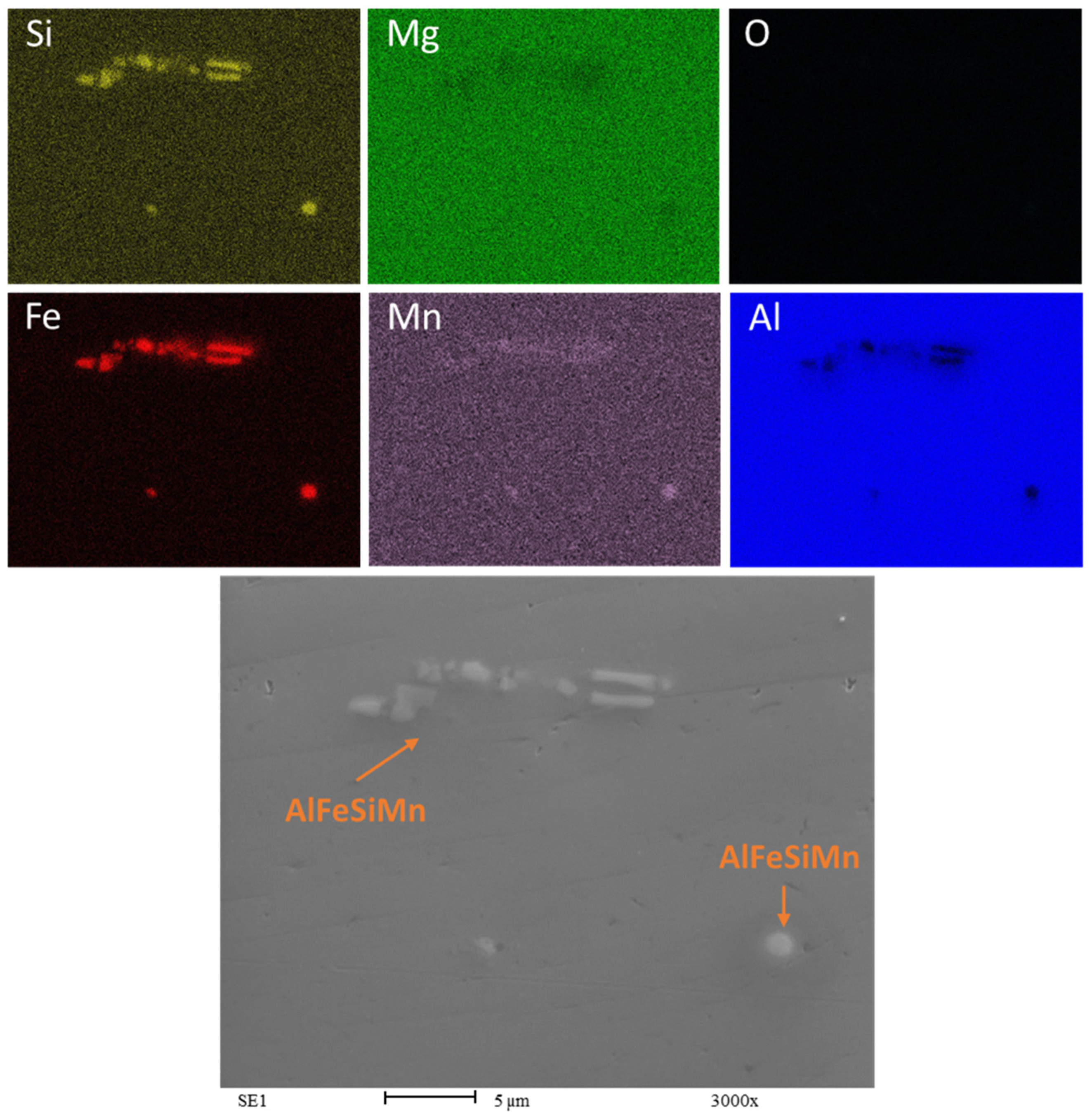
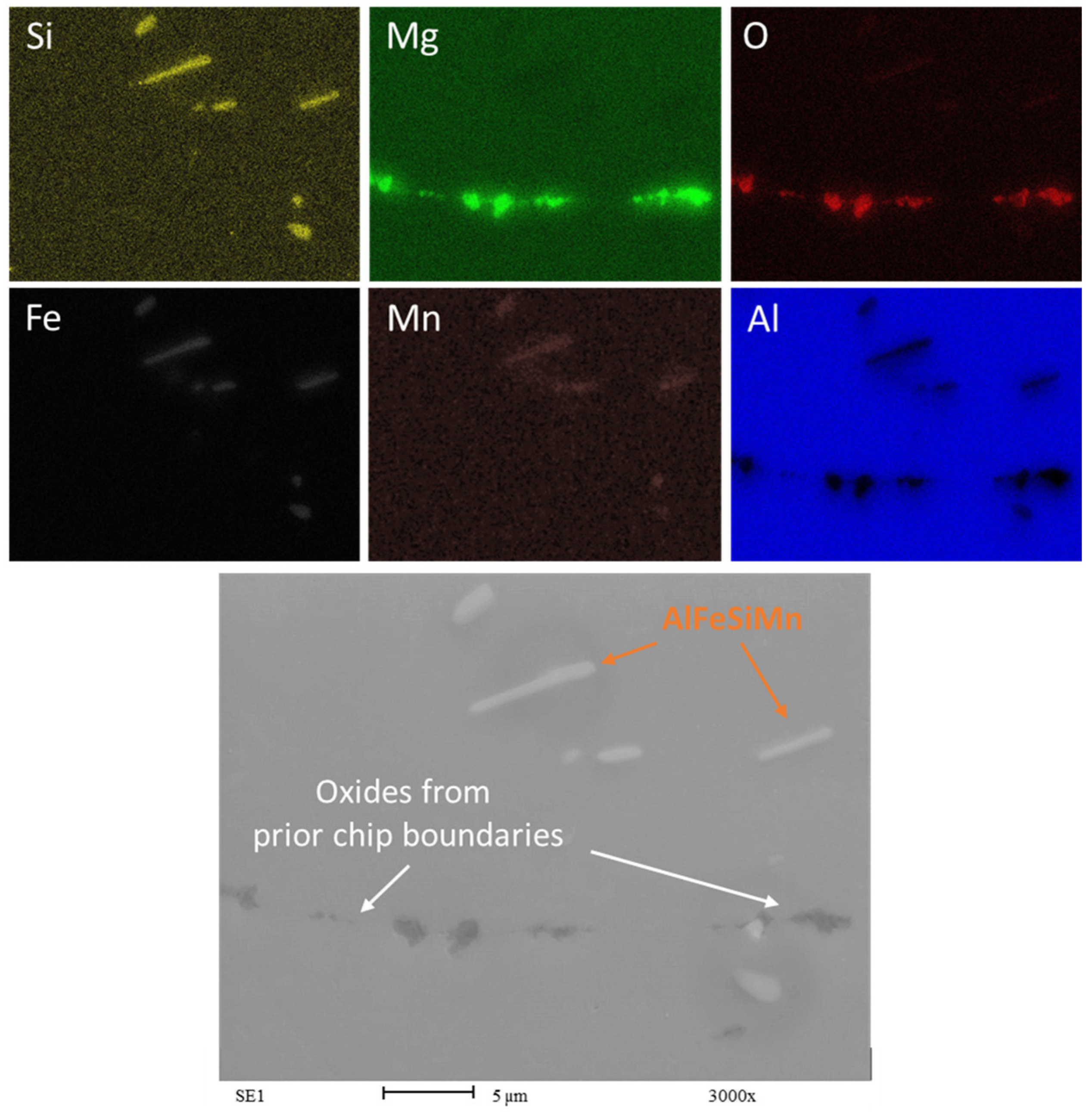
3.3. SEM and EDS Analysis

Figure 9 is a composite of Energy Dispersive X-ray Spectroscopy (EDS) maps of the AA6063 bulk HR1.0 sample.
The bright areas in the silicon and iron maps indicate the presence of β-AlFeSi intermetallics rich in these elements. These intermetallics appear in light gray in the SEM image at the bottom. The Mn map appears to be uniform except for few round-shaped spots, suggesting that these could be α-Al(MnFe)Si intermetallics [38,39]. From the EDS analysis, the composition of these intermetallics is 83.9 wt.% Al, 11.6 wt.% Fe, 3.6 wt.% Si, and 0.9 wt.% Mn.
The map of Mg is uniformly green, suggesting that magnesium is distributed throughout the matrix of the sample in solid solution. It is possible to detect the absence of oxygen within the detectable surface, meaning that the sample surface is free of oxidation, as might be expected in bulk samples.
The aluminum map shows a uniform distribution, except for a few isolated areas of low concentration where the concentration of other elements is higher. The presence and distribution of alloying elements and impurities can significantly affect the properties of the alloy. The presence of β-AlFeSi intermetallics may reduce the ductility of the alloy because they are typically harder and more brittle than the aluminum matrix. The needle-like or plate-like precipitates that can form in the case of β-AlFeSi can act as stress concentrators and crack initiation sites when subjected to stress or deformation.
The shape and distribution of the iron-rich phase within an alloy are influenced by various factors, including the alloying elements, the cooling rate, and iron content [40]. To address this issue, heat treatment is often employed to alter the shape of the particles from needle-like (acicular) to a more rounded form, α-Al(MnFe)Si, which enhances ductility.
An analogous evaluation can be applied to the EDS map of the Bulk CR1.0 sample shown in Figure 10. The only detectable particles within the sample are composed of aluminum, iron, silicon, and a small amount of manganese. The majority of these particles exhibit a needle-like morphology, suggesting that the β-AlFeSi are more numerous than α-Al(MnFe)Si phase.
The SEM analysis for the recycled chip samples yields results that are largely consistent with previous results; the main distinction is the presence not only of intermetallics, but also the persistent visibility of oxide particles (Figure 11 and Figure 12).
The observation of oxides aligned with the rolling direction (RD) and being broken indicates that the mechanical processing has affected the oxide inclusions within the AA6063 recycled chips. The oxides’ alignment and fragmentation pattern appear to result from the deformation process during rolling. Although the oxides have experienced fracturing due to the rolling process in both the HR1.0 and CR1.0 samples, the oxide particles in the HR1.0 have not been fragmented as finely as those in the AA6063 CR1.0.
In recycled chips, it is common to have more inclusions and higher oxygen content due to oxidation during machining. Whenever magnesium (Mg) is present as an alloying element, Aluminum oxide (Al2O3) consistently coexists with Magnesium oxide (MgO). This association has been reported by several studies in the literature [37,41]. The presence of MgO could locally affect the concentration of magnesium in the matrix. The oxidation of magnesium hinders the alloy strengthening through Mg2Si precipitation, as some of the magnesium is combined with oxygen. The presence of MgO is clearly visible in Figure 11 and Figure 12. The oxides form a complex network known as prior chip boundaries (PCBs), dividing the material into distinct regions. These boundaries primarily consist of oxides (MgO and Al2O3), with additional intermetallic compounds and precipitates. Similar to the extrusion process, in the recycling process based on rolling, the thin oxide layers originally present may increase during all the steps of the recycling process at high temperatures, from the heat treatment to the hot rolling passes. The oxides are aligned with the rolling direction (RD), indicating the effect of mechanical processing. The cold-rolled samples (CR1.0) show finer fragmentation compared to the hot-rolled samples (HR1.0), highlighting the impact of rolling temperature on oxide distribution. In any case, the breakage of the oxides is favorable to the continuity of the matrix and could be considered a way to determine the quality of the bonding between chips, enhancing the recycling process.

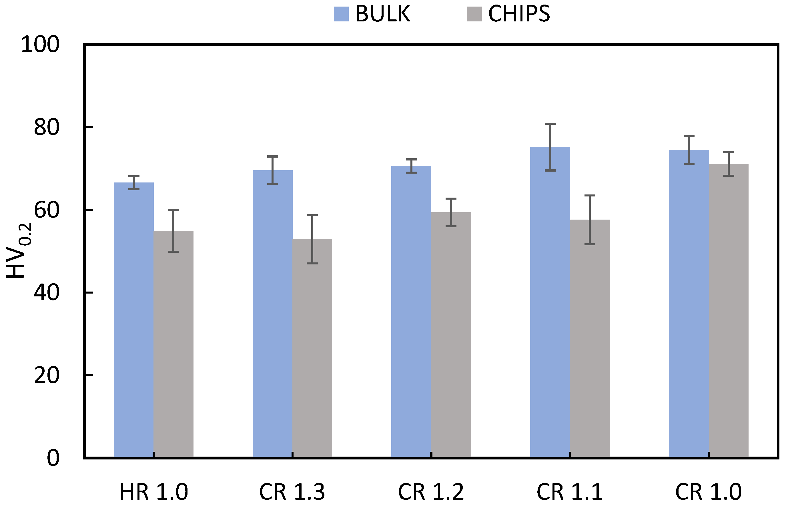
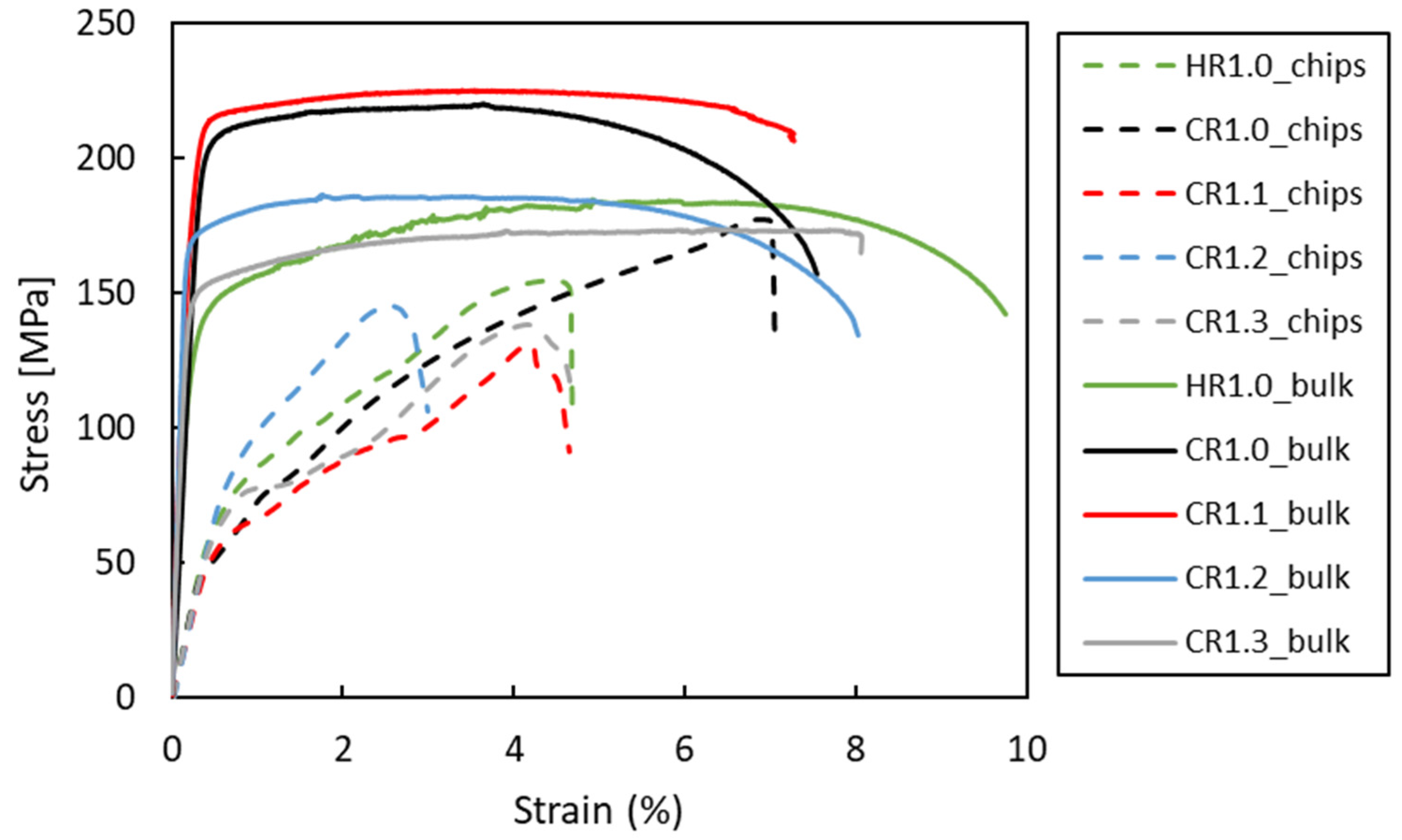
3.4. Mechanical Properties

Figure 13 shows the microhardness results for the rolled samples. The as-received material exhibits an average hardness of 61.1 HV. The bulk material demonstrates an increase in hardness with increasing cold plastic deformation. In contrast, the HR condition shows lower hardness compared to the other conditions, which can be attributed to the effect of recovery and recrystallization rather than the strengthening effect of cold rolling.
Since AA6063 is a heat-treatable aluminum alloy, the potential for strengthening through cold working is limited. Nevertheless, among the recycled samples, the CR1.0 condition exhibited the highest hardness. This sample underwent hot rolling to 1.5 mm followed by cold rolling to 1.0 mm, indicating a more severe plastic deformation in the final step. The extensive deformation resulted in greater hardening of the rolled chips compared to other conditions, which involved cold rolling from 1.5 mm to final thicknesses of 1.1 mm, 1.2 mm, and 1.3 mm. Notably, the hardness of the CR1.0 sample surpassed both the other rolled conditions and the as-received material. This suggests that the larger plastic deformation under this condition results in greater strengthening of the rolled chips. A comparison between the HR1.0 and CR1.0 samples clearly demonstrates that the final cold rolling pass, rather than hot rolling, is primarily responsible for the enhanced hardness, which is attributed to the strain hardening effect.
Figure 14 presents the stress–strain curves obtained from the tensile tests of all samples, and the corresponding mechanical properties are summarized in Table 3. Since an extensometer could not be used on the recycled chip samples due to their poor surface quality, the curve profiles differed significantly from those of the bulk samples, particularly in the elastic region. The UTS of the bulk material increased with the cold rolling strain applied to the samples. However, this improvement was accompanied by a decrease in ductility due to the strengthening effect. Compared to CR1.0, the HR1.0 condition has a higher elongation and a lower UTS.
Compared to the as-received material (UTS = 186 MPa, elongation = 22%), the processed (CR) samples exhibited a higher UTS but reduced ductility. The absence of subsequent heat treatment in the as-rolled condition likely contributed to this discrepancy. EDS analysis revealed a significant presence of β-AlFeSi intermetallic phases in both the CR1.0 and HR1.0 bulk samples, which are known to diminish ductility.
The CR1.0 sample had the highest UTS (~180 MPa) and elongation (7%) of all the recycled chips, consistent with the microhardness results. The considerable plastic deformation that occurs during cold rolling to 1.0 mm enhanced the strength and improved chip consolidation, leading to increased ductility.
The HR1.0 chips, which are hot-rolled to a thickness of 1.0 mm, are less ductile and have a lower ultimate tensile strength (UTS) than the CR1.0 chips. This comparison emphasizes the importance of extensive cold plastic deformation in enhancing the mechanical properties of recycled chips. Considering all the evaluated conditions, the process with the highest cold work resulted in the most pronounced increases in ductility and UTS. Nonetheless, all recycled samples displayed a lower UTS and elongation (A%) in comparison to the bulk material.

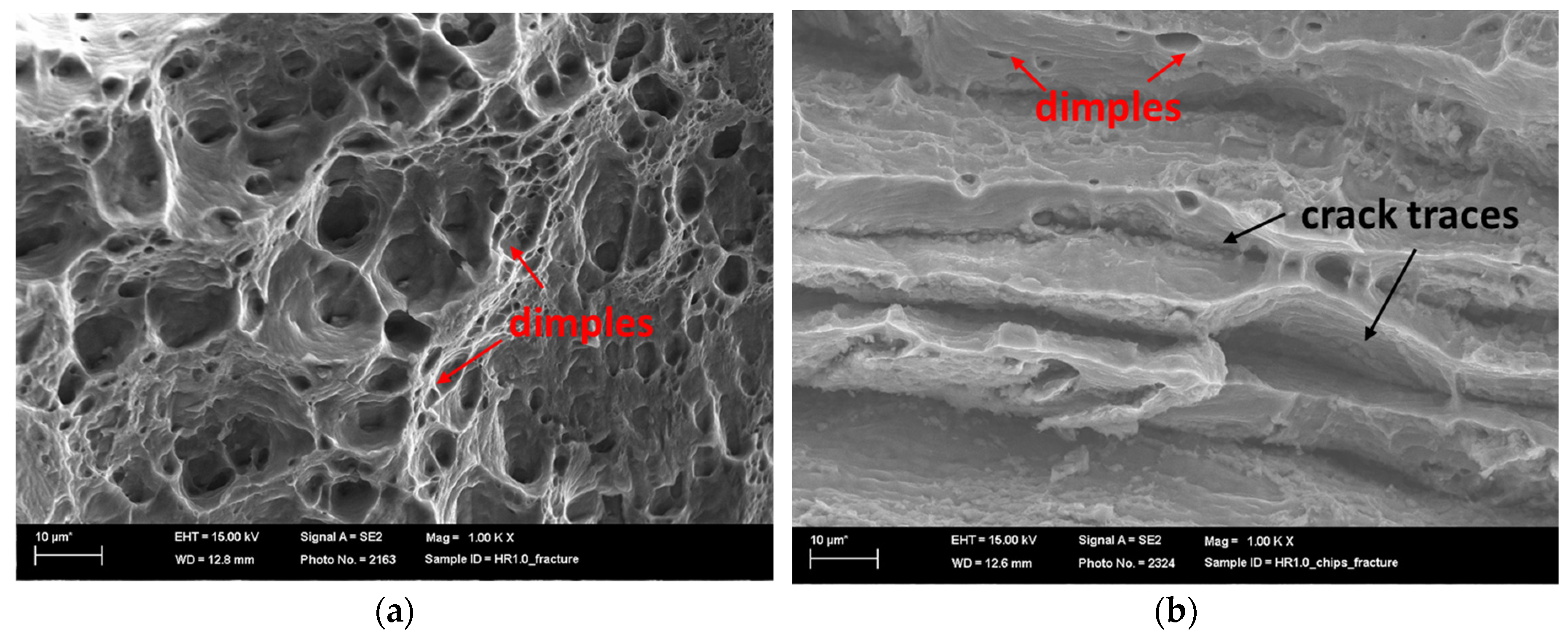
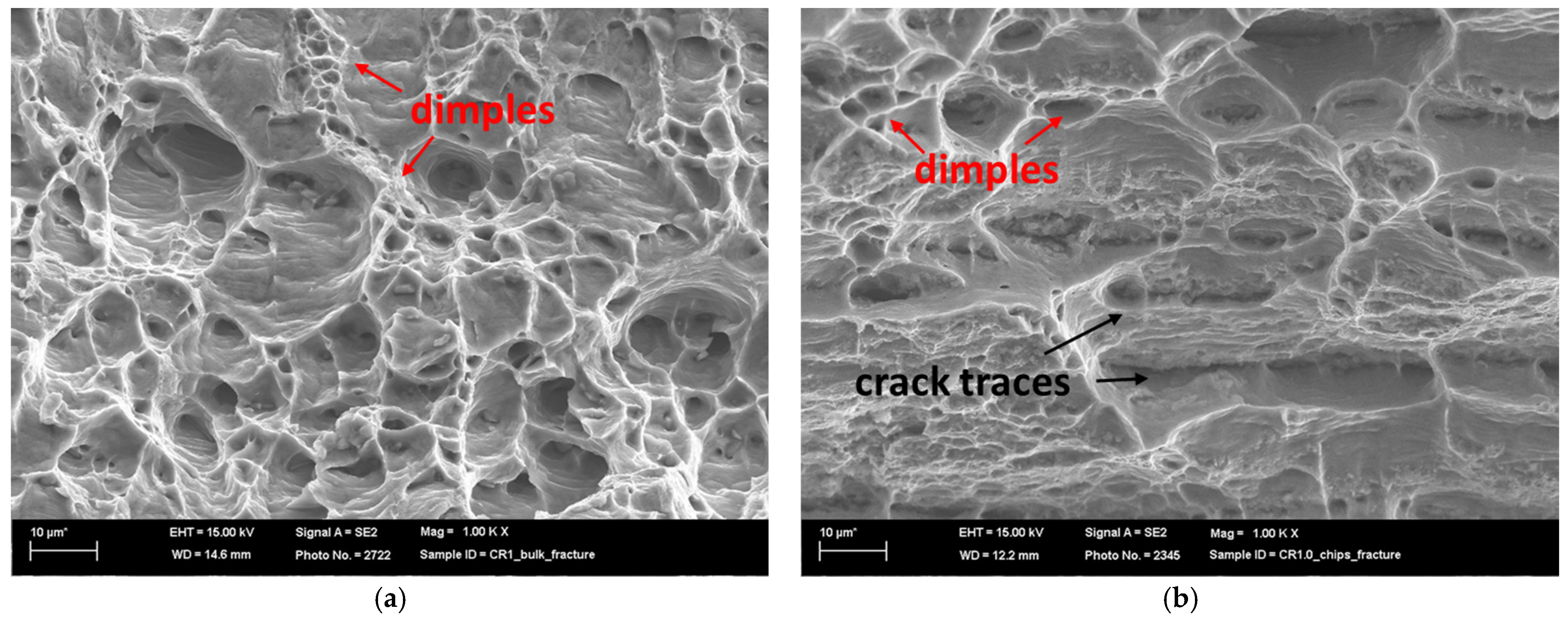
3.5. Fracture Surface

Figure 15 presents SEM fracture surfaces of the chip and bulk materials hot-rolled to 1.0 mm at 1000× magnification.
The bulk sample of HR1.0 exhibited a primarily ductile fracture morphology, with numerous dimples and voids. These characteristics suggest that void nucleation, growth, and coalescence led to ductile failure. Differences in dimple distribution and size indicate non-uniform stress or microstructural heterogeneity. Intermetallic β-AlFeSi phases were evident within many voids. The absence of pronounced layered structures implies good material cohesion and uniformity, as expected for bulk materials.
In contrast, the HR1.0 chip sample exhibited a mixed fracture mode including both ductile and planar features. The elongated, layered regions suggest incomplete chip bonding or preferential fracture paths along the prior chip boundaries. Smaller dimples and voids interspersed within these regions indicate localized plastic deformation. The mixed fracture behavior likely arises from the challenges associated with chip consolidation, leading to a combination of well-bonded regions and potential weak points or defects.
In summary, the base material sample exhibits a classic ductile fracture pattern (Figure 15a), whereas the chip-derived material (Figure 15b) demonstrates a more complex fracture mode influenced by its origin and complexities associated with chip consolidation.
Similar results were obtained by analyzing the SEM images of the fracture surfaces of the CR1.0 bulk and chip samples (Figure 16).
The bulk sample’s fracture surface demonstrated a predominantly ductile failure mode, with a dense distribution of dimples and microvoids. These microvoids, which indicate ductile fracture, form as a result of void nucleation, growth, and coalescence while deforming. The microvoids’ relatively uniform size and distribution suggest a consistent stress distribution within the material. Intermetallic β-AlFeSi particles frequently serve as nucleation sites for microvoids. The absence of pronounced layered or laminar structures is indicative of the inherent cohesion of the material, as expected in bulk materials.
In contrast, the recycled chip sample displayed a mixed fracture morphology that combined ductile and brittle characteristics. There are elongated laminar regions, which could represent original chip boundaries or material inhomogeneities, interspersed with ductile dimple formation. This mixed fracture behavior demonstrates the difficulties associated with consolidating recycled chips, which results in a mix of well-bonded regions and potentially weak interfaces.
Their mechanical properties support these findings. While recycled chips typically have a lower UTS and elongation than the bulk material, the CR1.0 condition is closer to the bulk properties. However, both conditions differed significantly from the as-received material, which had 22% elongation. Fracture surface analysis revealed that β-AlFeSi particles caused reduced ductility in the bulk material by acting as void nucleation sites. The layered fracture morphology of the recycled chips demonstrates that poor inter-chip bonding is the primary factor limiting ductility.

4. Conclusions

This study successfully demonstrates the feasibility of a novel solid-state recycling process, Direct Hot Rolling (DHR), for aluminum alloy AA6063 chips. In particular, the following were observed:
  • The recycled chip samples achieved good mechanical properties, particular in the CR1.0 condition, where the bulk exhibited a UTS of 218 MPa, and the recycled chips reached 177 MPa with similar elongation.
  • Microstructural analysis revealed a layered structure in all recycled chips. This is due to the inherent nature of the base material. SEM and EDS analysis showed broken oxide layers on the recycled material, facilitating aluminum matrix continuity and aligning with the rolling direction. The presence of Mg in the alloy leads to the formation of a mixed oxide layer (aluminum and magnesium oxides) on the chips.
  • By varying rolling schedules, in the recycled samples, it was found that cold rolling in the final pass enhanced the mechanical properties to a UTS of 177 MPa (CR1.0 condition) compared with just hot rolling (155 MPa in the HR1.0 condition).
  • SEM analysis revealed distinct fractures in the bulk and chips. The bulk material fractured in a ductile manner, while the chips showed a mixed mode due to consolidation challenges.
  • Given the oxidation of magnesium, recycling aluminum–silicon–magnesium alloys from chips requires the addition of magnesium to ensure the effectiveness of the aging treatment.
This research highlights the potential environmental benefits of solid-state recycling of aluminum alloys. By eliminating the need for remelting, DHR reduces energy consumption and greenhouse gas emissions compared to traditional recycling methods.
Future studies will focus on investigating the effect of heat treatment parameters to further enhance the mechanical properties and microstructural homogeneity of recycled material. The DHR process can be easily integrated into existing industrial rolling plants with minimal modifications, providing a cost-effective and environmentally friendly recycling route. However, for successful industrial application, the possibility of mixing 6xxx and 5xxx alloys could be studied to increase the overall Mg content in the recycled alloy, compensating for losses due to oxidation.

Author Contributions

Conceptualization, M.C., M.E.M. and P.B.; methodology, M.C., N.B.K. and M.E.M.; software, M.C. and M.E.M.; validation, M.C., N.B.K. and P.B.; formal analysis, M.C., R.E.M. and P.B.; investigation, M.C., F.B., R.E.M. and P.B.; resources, M.C., N.B.K. and M.E.M.; data curation, M.C., R.E.M. and F.B.; writing—original draft preparation, M.C.; writing—review and editing, M.C., M.E.M., N.B.K. and P.B.; visualization, M.C.; supervision, N.B.K. and M.E.M.; project administration, N.B.K. and M.E.M.; funding acquisition, M.E.M. All authors have read and agreed to the published version of the manuscript.

Funding

This research received no external funding.

Data Availability Statement

The original contributions presented in this study are included in the article; further inquiries can be directed to the corresponding author/s.

Conflicts of Interest

The authors declare no conflicts of interest.

References

  1. Das, S.K.; Yin, W. The Worldwide Aluminum Economy: The Current State of the Industry. JOM 2007, 59, 57–63. [Google Scholar] [CrossRef]
  2. Brough, D.; Jouhara, H. The Aluminium Industry: A Review on State-of-the-Art Technologies, Environmental Impacts and Possibilities for Waste Heat Recovery. Int. J. Thermofluids 2020, 1–2, 100007. [Google Scholar] [CrossRef]
  3. Wagiman, A.; Mustapa, M.S.; Asmawi, R.; Shamsudin, S.; Lajis, M.A.; Mutoh, Y. A Review on Direct Hot Extrusion Technique in Recycling of Aluminium Chips. Int. J. Adv. Manuf. Technol. 2020, 106, 641–653. [Google Scholar] [CrossRef]
  4. Balomenos, E.; Panias, D.; Paspaliaris, I. Energy and Exergy Analysis of the Primary Aluminum Production Processes: A Review on Current and Future Sustainability. Miner. Process. Extr. Metall. Rev. 2011, 32, 69–89. [Google Scholar] [CrossRef]
  5. Tan, R.B.H.; Khoo, H.H. An LCA Study of a Primary Aluminum Supply Chain. J. Clean. Prod. 2005, 13, 607–618. [Google Scholar] [CrossRef]
  6. Güley, V.; Ben Khalifa, N.; Tekkaya, A.E. Direct Recycling of 1050 Aluminum Alloy Scrap Material Mixed with 6060 Aluminum Alloy Chips by Hot Extrusion. Int. J. Mater. Form. 2010, 3, 853–856. [Google Scholar] [CrossRef]
  7. Capuzzi, S.; Timelli, G. Preparation and Melting of Scrap in Aluminum Recycling: A Review. Metals 2018, 8, 249. [Google Scholar] [CrossRef]
  8. Paraskevas, D.; Vanmeensel, K.; Vleugels, J.; Dewulf, W.; Duflou, J.R. Solid State Recycling of Aluminium Sheet Scrap by Means of Spark Plasma Sintering. Key Eng. Mater. 2015, 639, 493–498. [Google Scholar] [CrossRef]
  9. Gronostajski, J.; Marciniak, H.; Matuszak, A. New Methods of Aluminium and Aluminium-Alloy Chips Recycling. J. Mater. Process. Technol. 2000, 106, 34–39. [Google Scholar] [CrossRef]
  10. Shamsudin, S.; Lajis, M.; Zhong, Z. Solid-State Recycling of Light Metals: A Review. Adv. Mech. Eng. 2016, 8, 168781401666192. [Google Scholar] [CrossRef]
  11. Pantke, K.; Güley, V.; Khalifa, N.B.; Heilmann, M.; Biermann, D.; Tekkaya, A.E. Aluminum Scrap Recycling by Hot Extrusion without Melting Process. In Proceedings of the 12th International Conference on Aluminium Alloys, Yokohama, Japan, 5–9 September 2010; p. 6. [Google Scholar]
  12. Tekkaya, A.E.; Güley, V.; Haase, M.; Jäger, A. Hot Extrusion of Aluminum Chips. In ICAA13 Pittsburgh: Proceedings of the 13th International Conference on Aluminum Alloys; Springer International Publishing: Cham, Switzerland, 2016; pp. 1559–1573. [Google Scholar]
  13. Mehtedi, M.E.; Forcellese, A.; Mancia, T.; Simoncini, M.; Spigarelli, S. A New Sustainable Direct Solid State Recycling of AA1090 Aluminum Alloy Chips by Means of Friction Stir Back Extrusion Process. Procedia CIRP 2019, 79, 638–643. [Google Scholar] [CrossRef]
  14. Carta, M.; Buonadonna, P.; El Mehtedi, M. Numerical Analysis of Process Parameters and Tool Geometry in Friction Stir Back Extrusion of Pure Aluminum. Procedia CIRP 2024, 126, 710–714. [Google Scholar] [CrossRef]
  15. Tahmasbi, K.; Mahmoodi, M.; Tavakoli, H. Corrosion Resistance of Aluminum Alloy AA7022 Wire Fabricated by Friction Stir Extrusion. Trans. Nonferrous Met. Soc. China 2019, 29, 1601–1609. [Google Scholar] [CrossRef]
  16. Li, X.; Baffari, D.; Reynolds, A.P. Friction Stir Consolidation of Aluminum Machining Chips. Int. J. Adv. Manuf. Technol. 2018, 94, 2031–2042. [Google Scholar] [CrossRef]
  17. Wahed, S.N.A.; Hussein, S.K.; Al-Saadi, M.H. Disc Forming by Friction Stir Consolidation of AA2024 Chips. J. Technol. 2022, 4, 1–8. [Google Scholar] [CrossRef]
  18. Al-Alimi, S.; Lajis, M.A.; Shamsudin, S. Solid-State Recycling of Light Metal Reinforced Inclusions by Equal Channel Angular Pressing: A Review. MATEC Web Conf. 2017, 135, 00013. [Google Scholar] [CrossRef]
  19. Krolo, J.; Lela, B.; Dumanić, I.; Kozina, F. Statistical Analysis of the Combined ECAP and Heat Treatment for Recycling Aluminum Chips Without Remelting. Metals 2019, 9, 660. [Google Scholar] [CrossRef]
  20. Paraskevas, D.; Dadbakhsh, S.; Vleugels, J.; Vanmeensel, K.; Dewulf, W.; Duflou, J.R. Solid State Recycling of Pure Mg and AZ31 Mg Machining Chips via Spark Plasma Sintering. Mater. Des. 2016, 109, 520–529. [Google Scholar] [CrossRef]
  21. Paraskevas, D.; Vanmeensel, K.; Vleugels, J.; Dewulf, W.; Deng, Y.; Duflou, J. Spark Plasma Sintering as a Solid-State Recycling Technique: The Case of Aluminum Alloy Scrap Consolidation. Materials 2014, 7, 5664–5687. [Google Scholar] [CrossRef]
  22. Altharan, Y.M.; Shamsudin, S.; Al-Alimi, S.; Saif, Y.; Zhou, W. A Review on Solid-State Recycling of Aluminum Machining Chips and Their Morphology Effect on Recycled Part Quality. Heliyon 2024, 10, e34433. [Google Scholar] [CrossRef]
  23. Paraskevas, D.; Kellens, K.; Deng, Y.; Dewulf, W.; Kampen, C.; Duflou, J.R. Solid State Recycling of Aluminium Alloys via a Porthole Die Hot Extrusion Process: Scaling up to Production. AIP Conf. Proc. 2017, 1896, 140008. [Google Scholar] [CrossRef]
  24. Bochniak, W.; Ostachowski, P.; Korbel, A.; Łagoda, M. Potential of the KOBO Extrusion Process for Nonferrous Metals in the Form of Solids and Chips. Int. J. Adv. Manuf. Technol. 2023, 127, 733–750. [Google Scholar] [CrossRef]
  25. Suzuki, K.; Huang, X.S.; Watazu, A.; Shigematsu, I.; Saito, N. Recycling of 6061 Aluminum Alloy Cutting Chips Using Hot Extrusion and Hot Rolling. Mater. Sci. Forum 2007, 544–545, 443–446. [Google Scholar] [CrossRef]
  26. Chiba, R.; Nakamura, T.; Kuroda, M. Solid-State Recycling of Aluminium Alloy Swarf through Cold Profile Extrusion and Cold Rolling. J. Mater. Process. Technol. 2011, 211, 1878–1887. [Google Scholar] [CrossRef]
  27. Allwood, J.M.; Huang, Y.; Barlow, C.Y. Recycling Scrap Aluminium by Cold-Bonding. In Proceedings of the 8th International Conference on Technology Plasticity, Verona, Italy, 9–13 October 2005. [Google Scholar]
  28. Kore, A.S.; Nayak, K.C.; Date, P.P. Formability of Aluminium Sheets Manufactured by Solid State Recycling. J. Phys. Conf. Ser. 2017, 896, 012007. [Google Scholar] [CrossRef]
  29. El Mehtedi, M.; Buonadonna, P.; Carta, M.; El Mohtadi, R.; Mele, A.; Morea, D. Sustainability Study of a New Solid-State Aluminum Chips Recycling Process: A Life Cycle Assessment Approach. Sustainability 2023, 15, 11434. [Google Scholar] [CrossRef]
  30. Carta, M.; Ben Khalifa, N.; Buonadonna, P.; Mele, A.; El Mehtedi, M. Life Cycle Assessment (LCA) of a Novel Solid-State Recycling Process for Aluminum Alloy AA6063 Chips via Direct Hot Rolling. In Proceedings of the Material Forming—ESAFORM 2024, Toulouse, France, 25 May 2024; pp. 2881–2890. [Google Scholar]
  31. El Mehtedi, M.; Buonadonna, P.; El Mohtadi, R.; Loi, G.; Aymerich, F.; Ben Khalifa, N.; Carta, M. Feasibility Study of Solid-State Recycling through Direct Hot Rolling of AA5754 Aluminum Chips for Automotive Applications. Mater. Sci. Forum 2024, 1130, 3–12. [Google Scholar] [CrossRef]
  32. De Caro, D.; Tedesco, M.M.; Pujante, J.; Bongiovanni, A.; Sbrega, G.; Baricco, M.; Rizzi, P. Effect of Recycling on the Mechanical Properties of 6000 Series Aluminum-Alloy Sheet. Materials 2023, 16, 6778. [Google Scholar] [CrossRef]
  33. ASTM E8/E8M-22; Standard Test Methods for Tension Testing of Metallic Materials. ASTM International: West Conshohocken, PA, USA, 2024.
  34. BS EN 895:1997; British Standards Institution: London, UK, 1997.
  35. Hielscher, R.; Schaeben, H.; Siemes, H. Orientation Distribution Within a Single Hematite Crystal. Math. Geosci. 2010, 42, 359–375. [Google Scholar] [CrossRef]
  36. Bachmann, F.; Hielscher, R.; Schaeben, H. Texture Analysis with MTEX—Free and Open Source Software Toolbox. Solid State Phenom. 2010, 160, 63–68. [Google Scholar] [CrossRef]
  37. Zhang, Z.; Liang, J.; Xia, T.; Xie, Y.; Chan, S.L.I.; Wang, J.; Zhang, D. Effects of Oxide Fragments on Microstructure and Mechanical Properties of AA6061 Aluminum Alloy Tube Fabricated by Thermomechanical Consolidation of Machining Chips. Materials 2023, 16, 1384. [Google Scholar] [CrossRef]
  38. Kuijpers, N.C.W.; Vermolen, F.J.; Vuik, C.; Koenis, P.T.G.; Nilsen, K.E.; Zwaag, S.V.D. The Dependence of the β-AlFeSi to α-Al(FeMn)Si Transformation Kinetics in Al–Mg–Si Alloys on the Alloying Elements. Mater. Sci. Eng. A 2005, 394, 9–19. [Google Scholar] [CrossRef]
  39. Que, Z.; Mendis, C.L. Heterogeneous Nucleation and Phase Transformation of Fe-Rich Intermetallic Compounds in Al–Mg–Si Alloys. J. Alloys Compd. 2020, 836, 155515. [Google Scholar] [CrossRef]
  40. Alvarez-Antolin, F.; Asensio-Lozano, J.; Cofiño-Villar, A.; Gonzalez-Pociño, A. Analysis of Different Solution Treatments in the Transformation of β-AlFeSi Particles into α-(FeMn)Si and Their Influence on Different Ageing Treatments in Al–Mg–Si Alloys. Metals 2020, 10, 620. [Google Scholar] [CrossRef]
  41. Laurent-Brocq, M.; Lilensten, L.; Pinot, C.; Schulze, A.; Duchaussoy, A.; Bourgon, J.; Leroy, E.; Tekkaya, A.E. Solid State Recycling of Aluminium Chips: Multi-Technique Characterization and Analysis of Oxidation. Materialia 2023, 31, 101864. [Google Scholar] [CrossRef]
Figure 1. Schematic flow chart of the experimental procedure.
Metals 14 01442 g001
Figure 2. (a) Chips before and after cold compaction; (b) picture of the die design used for compaction (all measures in mm).
Metals 14 01442 g002
Figure 3. Schematic representation of the process.
Metals 14 01442 g003
Figure 4. Hot-rolled samples following schedule in Table 2 (a) for chips and (b) for bulk materials.
Metals 14 01442 g004
Figure 5. Tensile sample scheme and dimension (all measures in mm).
Metals 14 01442 g005
Figure 6. Optical micrograph of (a) Bulk HR1.0 sample, (b) Bulk CR1.0 sample, (c) Bulk CR1.1 sample, (d) Bulk CR1.2 sample, (e) Bulk CR1.3 sample, (f) Chips HR1.0 sample, (g) Chips CR1.0 sample, (h) Chips CR1.1 sample, (i) Chips CR1.2 sample, and (j) Chips CR1.3 sample. Rolling direction (RD) is parallel to the scale bar.
Metals 14 01442 g006aMetals 14 01442 g006b
Figure 7. EBSD analysis of the CR1.0 samples. (a) IPF map of Bulk CR1.0; (b) IPF map of CR1.0 chips. Histogram of misorientation grain angle, respectively, for bulk (c) CR1.0 and (d) CR1.0 chips. Rolling direction (RD) is parallel to the scale bar.
Metals 14 01442 g007
Figure 8. EBSD analysis of the HR1.0 samples. (a) IPF map of Bulk HR1.0; (b) IPF map of HR1.0 chips; and histogram of misorientation angle, respectively, for bulk (c) HR1.0 and (d) HR1.0 chips. Rolling direction (RD) is parallel to the scale bar.
Metals 14 01442 g008
Figure 9. EDS map of Bulk HR1.0. Rolling direction (RD) is parallel to the scale bar.
Metals 14 01442 g009
Figure 10. EDS maps of Bulk CR1.0. Rolling direction (RD) is parallel to the scale bar.
Metals 14 01442 g010
Figure 11. EDS maps of Chips CR1.0. Rolling direction (RD) is parallel to the scale bar.
Metals 14 01442 g011
Figure 12. EDS map of Chips HR1.0. Rolling direction (RD) is parallel to the scale bar.
Metals 14 01442 g012
Figure 13. Microhardness HV0.2 (obtained using 0.2 kgf) in as-rolled conditions of bulk and chip samples with different final thicknesses.
Metals 14 01442 g013
Figure 14. Representative stress vs. strain curves for the studied conditions.
Metals 14 01442 g014
Figure 15. Fracture surface of HR 1.0 bulk (a) and HR 1.0 chips (b).
Metals 14 01442 g015
Figure 16. Fracture surface of CR1.0 bulk (a) and chips (b).
Metals 14 01442 g016
Table 1. Chemical composition of the alloy (wt.%).
ElementSiFeCuMnMgCrNiZnTiAl
wt.%0.5850.2310.0270.0300.4890.0070.0070.0330.018Bal.
Table 2. Rolling schedules. The rolling passes are the same until the 7th pass. The last rolling pass is different for every sample (hx indicates the thickness after the “x” rolling pass).
Number of Passesh0h1h2h3h4h5h6h7h8
Chip billet [mm]10.5964.53.32.521.51.3/1.2/1.1/1.0
Bulk billet [mm]10.5964.53.32.521.51.3/1.2/1.1/1.0
Table 3. Ultimate tensile strength (UTS) and elongation to failure (A%) of all samples, in as-rolled conditions.
MaterialTensile
Properties
HR 1.0CR 1.3CR 1.2CR 1.1CR 1.0As Received (O)
BulkUTS [MPa]182.3 ± 3.7175.0 ± 1.2185.4 ± 1.6221.1 ± 6.0219.1 ± 1.7186
A%8.7 ± 1.68.1 ± 2.08.0 ± 1.57.5 ± 1.87.5 ± 2.022
ChipsUTS [MPa]154.9 ± 14.2 138.4 ± 26.0145.5 ± 8.2131.3 ± 13.4177.4 ± 7.1-
A%4.7 ± 3.34.7 ± 3.23.0 ± 2.74.7 ± 2.77.0 ± 3.5-
Disclaimer/Publisher’s Note: The statements, opinions and data contained in all publications are solely those of the individual author(s) and contributor(s) and not of MDPI and/or the editor(s). MDPI and/or the editor(s) disclaim responsibility for any injury to people or property resulting from any ideas, methods, instructions or products referred to in the content.

