Article

Study on Deformation Behavior and Mechanical Properties of 42CrMo High-Strength Steel with Multi-Station Warm Upsetting

1
College of Mechanical and Electrical Engineering, Zhengzhou University of Light Industry, Zhengzhou 450002, China
2
School of Materials Science and Engineering, Tianjin University, Tianjin 300350, China
3
Sijin Intelligent Forming Machinery Company Limited Co., Ltd., Ningbo 453499, China
*
Authors to whom correspondence should be addressed.
Metals 2024, 14(2), 135; https://doi.org/10.3390/met14020135
Submission received: 26 December 2023 / Revised: 20 January 2024 / Accepted: 22 January 2024 / Published: 23 January 2024

Abstract

:
In order to find out the deformation behavior and mechanical properties of 42CrMo steel under warm upsetting conditions, the Gleeble-3500 thermal simulation testing machine was used to carry out a warm upsetting physical simulation experiment on 42CrMo steel. By controlling deformation temperature, strain rate, and constant temperature deformation pass, the microstructure evolution rule under different warm upsetting conditions was analyzed, and its hardness value was measured. Then, the simulation experiment is carried out based on the Deform-3D finite element platform. The results show that, with the increase in deformation temperature, 42CrMo steel has a temperature rise softening effect, which significantly reduces the peak value of rheological stress. At 650 °C, the maximum peak value of rheological stress is only 45.3% of that of cold upsetting deformation at room temperature, and the stress-strain curve tends to be gentle at the plastic deformation stage, which is the most suitable temperature for warm upsetting deformation. The maximum peak flow stress of 42CrMo steel increases with the increase in strain rate, but the number of deformation channels has little influence on the stress-strain curve. The warm, upsetting deformation can refine the internal grain structure significantly, and the grain refinement mechanism is mechanical crushing. When the temperature is slightly higher, the broken grain will recover, and the grain size will grow. During the process of warm upsetting, the strain rate has a great influence on the microhardness of the sample. The deformation pass has little influence on the hardness, and the hardness increases slightly with the increase in the deformation pass. Through the Deform-3D simulation, the correlation coefficient R and the average absolute relative error (AARE) between the simulation value and the experimental value were calculated, and the correlation coefficient R-value was 0.9948, and the average absolute relative error (AARE) was 2.05%, indicating that the simulation can accurately reflect the relationship between displacement and applied load.

1. Introduction

Fasteners are widely used in machinery, electrical, automotive, transportation, aerospace, and other fields. With the professional and large-scale development of fastener manufacturing, higher requirements are also put forward for the manufacture of fasteners. At present, the most common manufacturing method for fasteners is the cold upsetting process [1,2]. However, due to the greater resistance to plastic deformation of metal materials at room temperature and the characteristics of cold work hardening, the deformation requires greater force, and the upsetting capability of equipment is limited in the manufacture of bolts and nuts with large specifications and deformation [3]. In order to make up for the shortcomings of the cold upsetting process, the hot upsetting process is also applied in a certain range [4,5], while the traditional hot upsetting process also has some problems in the production practice, such as that the billet temperature is not easy to control, the heating is not uniform, the heating time is long, and it is easy to cause over-burning, oxidation, and decarbonization, which is the main reason for the poor quality of the formed parts [6]. Due to the above reasons, the application of warm upsetting technology is promoted.
Warm upsetting technology is applied in fastener production, which solves the manufacturing quality problem of bolts and nuts that are difficult to deform. 42CrMo steel is one of the high-strength steels that is difficult to deform. Due to its high strength, high hardenability, fracture toughness, and wear resistance, it is widely used in bearings, flanges, high-strength bolts, and other fields [7,8,9]. Upsetting and heat treatment are key processing steps. In recent years, the compression studies of 42CrMo steel mostly focus on hot compression and rolling with the recrystallization temperature above 890 °C [10,11,12,13,14], but there are few studies on warm upsetting forming. Ji et al. [15] carried out high-temperature equal-diameter angle extrusion (ECAP) on 42CrMo steel above the austenite transformation temperature. The microstructure and material strength of the samples at different radial positions were characterized, and the test results showed that DRX of different degrees caused by the uneven distribution of strain and strain rate on the samples was the main reason for the gradient distribution of the radial microstructure and material strength. Y.C. Lin et al. [16] carried out hot compression experiments with different temperatures, deformation rates, and deformation degrees in order to conduct a numerical simulation of the forging of 42CrMo steel and establish its hot-forming process parameters. They also studied the effects of process parameters such as strain rate, forming temperature, and degree of deformation on the microstructure of 42CrMo steel. The results showed that the average grain size of 42CrMo steel increases with an increase in forming temperature and decreases with an increase in deformation degree and strain rate. Qian Dongsheng et al. [17] studied the grain evolution law of 42CrMo ring parts through simulation and experimentation in the processes of blanking, billet making, hot rolling, and residual heat quenching and concluded that in the process of residual heat quenching, the grain refinement of the central part of the ring is obvious, and the forming force of 42CrMo steel in the process of hot forming is small, but the surface is easy to produce an oxide layer, which needs further treatment.
In multi-pass forming, with the increase in deformation passes, the forming force can be significantly reduced each time, and large variable forming can be accumulated. In recent years, many scholars have studied multi-pass compression [18,19,20,21], among which the research on 42CrMo steel’s multi-pass deformation mainly focuses on the thermal compression experiment above the recrystallization temperature. Fangcheng Qin et al. [22] conducted an isothermal–non-isothermal multi-pass compression test on centrifugally cast 42CrMo steel at a temperature above recrystallization, studied the effects of compression pass and final rolling temperature on deformation behavior and microstructure evolution, and found that the flow stress did not change significantly with the increase in pass. However, controlled-temperature cumulative static recrystallization can make the grains fine and evenly distributed. Wanhui Huang et al. [23] studied the effects of high-temperature multi-direction multi-pass forging and annealing treatment on the microstructure and mechanical properties of 42CrMo steel and found that the average austenite grain size decreased significantly, and dislocation density increased after multi-pass forging. Qingfeng Zhu et al. [24] studied the effect of forging passes on the refining effect of high-purity aluminum during multi-directional forging at room temperature. The results showed that with the increase in forging passes, the fine crystal region in the center of the sample gradually expanded, and the size of coarse grains near the surface continuously decreased with the increase in forging passes to 24 passes.
In order to investigate the deformation behavior and mechanical properties of 42CrMo steel under the condition of warm upsetting, the Gleeble-3500 thermal simulation testing machine was used in this study to carry out the warm upsetting physical simulation experiments on 42CrMo steel at different temperatures, strain rates, and deformation passes. The study on the change in rheological behavior, microstructure, and mechanical properties of 42CrMo steel with warm upsetting parameters provides a theoretical basis for the multi-station warm upsetting deformation of 42CrMo steel.

2. Experimental Conditions and Numerical Simulation Conditions

42CrMo high-strength steel with slow cooling after hot rolling was selected as the material of this experiment, and the material was made into a cylindrical specimen with a diameter of 8 mm and a height of 12 mm by wire cutting, The 42CrMo obtained by this treatment has good comprehensive mechanical properties and is suitable for a warm upsetting process. 42CrMo steel is a kind of medium carbon low alloy steel. Its main chemical composition and content are 0.4 wt% C, 0.23 wt% Si, 0.6 wt% Mn, 0.98 wt% Cr, 0.18 wt% Mo, 0.019 wt% P, 0.012 wt% S, 0.02 wt% Cu.
In order to obtain the mechanical properties and microstructure of warm upsetting forming under different temperatures, strain rates and deformation passes, the constant rate cold upsetting and warm upsetting comparison test, the deformation evolution test, and the multi-pass warm upsetting test were carried out on the Gleeble-3500 thermal simulation test machine of DSI Company (Figure 1a).
The comparison test conditions of cold upsetting and warm upsetting at constant rates were as follows: under the condition of a heating rate of 10 °C/s and a strain rate of 1 s−1 dynamic load, the samples were heated to 20 °C, 500 °C, 650 °C, and 800 °C, respectively, for compression experiments, and the total deformation was 60%. The test conditions for the deformation evolution of warm upsetting were as follows: the sample was heated to 650 °C at a heating rate of 10 °C/s, and compression was carried out under the conditions of strain rates of 1, 10, and 15 s−1, respectively, and the total deformation was 60%. The experimental scheme is shown in Table 1. Multi-pass compression conditions are as follows: heating to 650 °C at a heating rate of 10 °C/s; compression tests for two and three passes are carried out at a deformation rate of 10 s−1. During the compression process, the temperature is maintained at not less than 650 °C, and force unloading and loading processes are carried out between each pass. The experimental scheme is shown in Table 2. Air cooling treatment after deformation is completed.
As shown in Figure 2a, the deformed specimen is cut parallel to the longitudinal compression axis. The section was ground and polished, and the surface was corroded with a 4% nitrate alcohol solution. The microstructure of the central area of the section was observed with an IE500M metallographic microscope, as shown in Figure 2b. Then, the average grain size is obtained by the number of grains per unit area.
Wolpert 430SVA Vickers hardness tester was used to measure Vickers hardness in the central region of the sample with different experimental parameters at room temperature. The test surface is polished with 200- to 2000-mesh metallographic abrasive paper and then polished with polishing paste to avoid flaring ash and debris. The load used for measurement was 10 kgf, the loading time was 20 s, the loading time was 15 s, and the unloading time was 10 s. Finally, the indentation diagonal of the positive pyramid indenter is measured, and the average hardness value of each sample is obtained by measuring at least three times for the same position. The calculation method is shown in Equation (1).
H V = 1.8544 p d 2
where HV is Vickers hardness (kgf/mm2), p is the applied load (kgf), d is the average of the diagonal lengths of the two indentations (mm), and 1.8544 is a constant.
Deform-3D Ver.11.0 finite element analysis software was used to simulate the deformation process of 42CrMo steel parameterized. First, the true stress-strain curve obtained from the compression experiment was imported into the software, and then the billet was set as a plastic body with a temperature of 650 °C. At the same time, the die temperature is set to 20 °C and defined as a rigid body; the contact factor between the billet and the die was set to warm upsetting 0.25, and the thermal conductivity was set to 11 N/s/mm/C. The die speed was set at 1 s−1, 10 s−1, and 15 s−1, respectively, and the billet was divided into 35,000 tetrahedral finite elements for analysis.

3. Analysis of Experimental Results of Warm Upsetting

3.1. Single-Station Warm Upsetting Forming Analysis

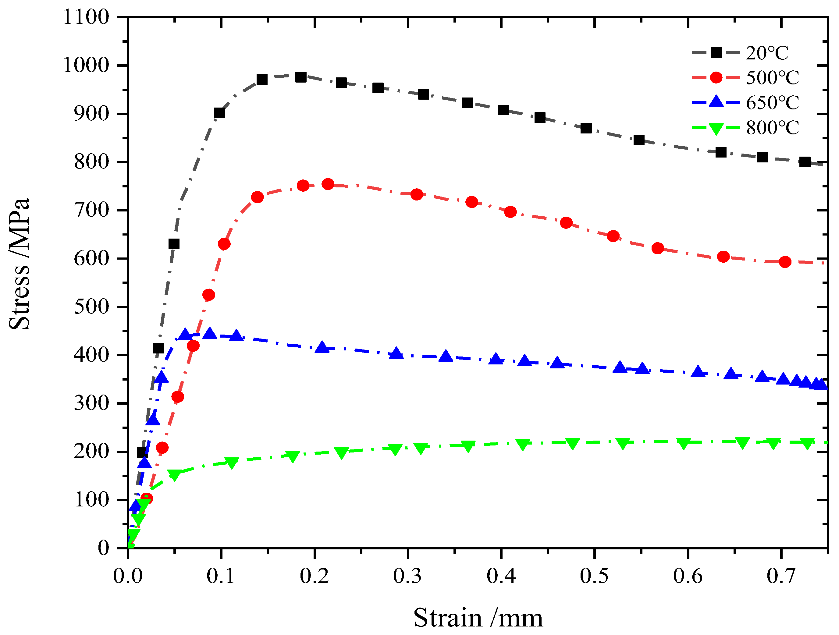
3.1.1. Influence of Deformation Temperature on Stress-Strain Curve of Single Station Upsetting Experiment

Figure 3 shows the true stress–strain curve of 42CrMo steel at 20~800 °C, a strain rate of 1 s−1, and a compression deformation of 60%. It can be seen from Figure 3 that the peak value of flow stress significantly decreases with the increase in temperature during the compression process, and in the plastic deformation stage, the stress–strain curve of cold upsetting forging at room temperature gradually decreases with the increase in deformation, resulting in rheological softening. When the blue brittleness temperature is exceeded, the curve tends to be gentle when the forging deformation is warm, and when the compression deformation is 800 °C, the curve gradually rises, resulting in deformation hardening. It can be seen from Figure 3 that the variation trend of the stress–strain curve with deformation temperature is consistent with the transformation trend of the stress-strain curve of carbon steel with cold deformation, warm deformation, and hot deformation. This is because temperature is one of the important factors affecting the stress-strain curve. With the increase in temperature, the kinetic energy between atoms increases, the binding force decreases, and the dislocation is more likely to overcome the pinning effect and move, resulting in a temperature rise softening effect, thus gradually reducing the peak metal flow stress [25]. When the temperature is between 20 °C and 650 °C, the softening effect of temperature rise is greater than that of work hardening, so the deformation is mainly softening, and the stress in the plastic deformation stage decreases with the increase in strain [26]. When the blue brittleness temperature is exceeded, the curve tends to flatten and rise at the plastic deformation stage, especially at 800 °C, which is close to the trend of the stress–strain curve of hot upsetting. It can be seen that when 42CrMo steel deforms at about 650 °C, the maximum peak flow stress is only 45.3% of the cold upsetting forging deformation at room temperature, and the stress–strain curve tends to be gentle in the plastic deformation stage, and it is in the best state of warm deformation.

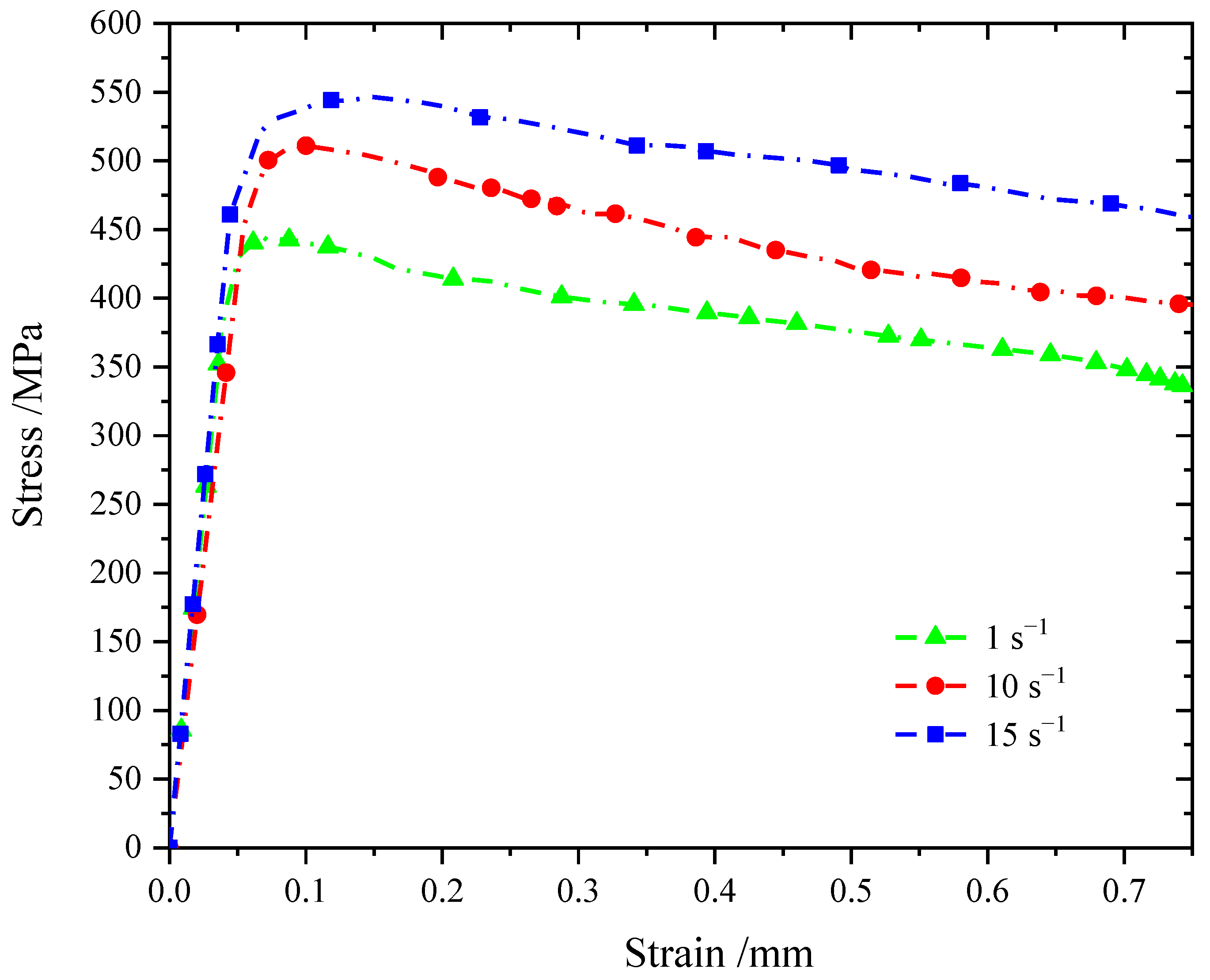
3.1.2. Influence of Strain Rate on the Stress–Strain Curve of the Single Station Warm Upsetting Forming Experiment

In order to physically simulate the effect of strain rate on the stress-strain curve of 42CrMo steel in the temperature range of warm upsetting forging, the upsetting test was carried out at 650 °C, with a strain rate ranging from 1 to 15 s−1 and compression deformation of 60%. The deformation characteristics are shown in Figure 4.
As can be seen from Figure 4, the sample was deformed under upsetting at a warm forming temperature, and the stress-strain curve of 42CrMo steel showed a trend of first increasing to the stress peak and then slowly decreasing, and with the increase in strain rate, the stress-strain curve increased. This is because, with the increase in deformation rate, dislocation density and dislocation proliferation speed increase rapidly in a short period of time, resulting in an increase in peak flow stress [27]. With the increase in compression deformation, the peak flow stress reaches 443.9 MPa, 511.0 MPa, and 546.5 MPa at the deformation rates of 1 s−1, 10 s−1, and 15 s−1, respectively. It can be seen that under the condition of warm deformation, the peak value of flow stress increases with the increase in deformation rate, and in the plastic stage, the stress value slowly decreases with the increase in strain. This change trend is similar to that of the flow curve under cold deformation, but the decreasing trend tends to be gentle. This shows that the softening effect caused by the rise in deformation temperature is gradually reduced under the condition of warm forming.

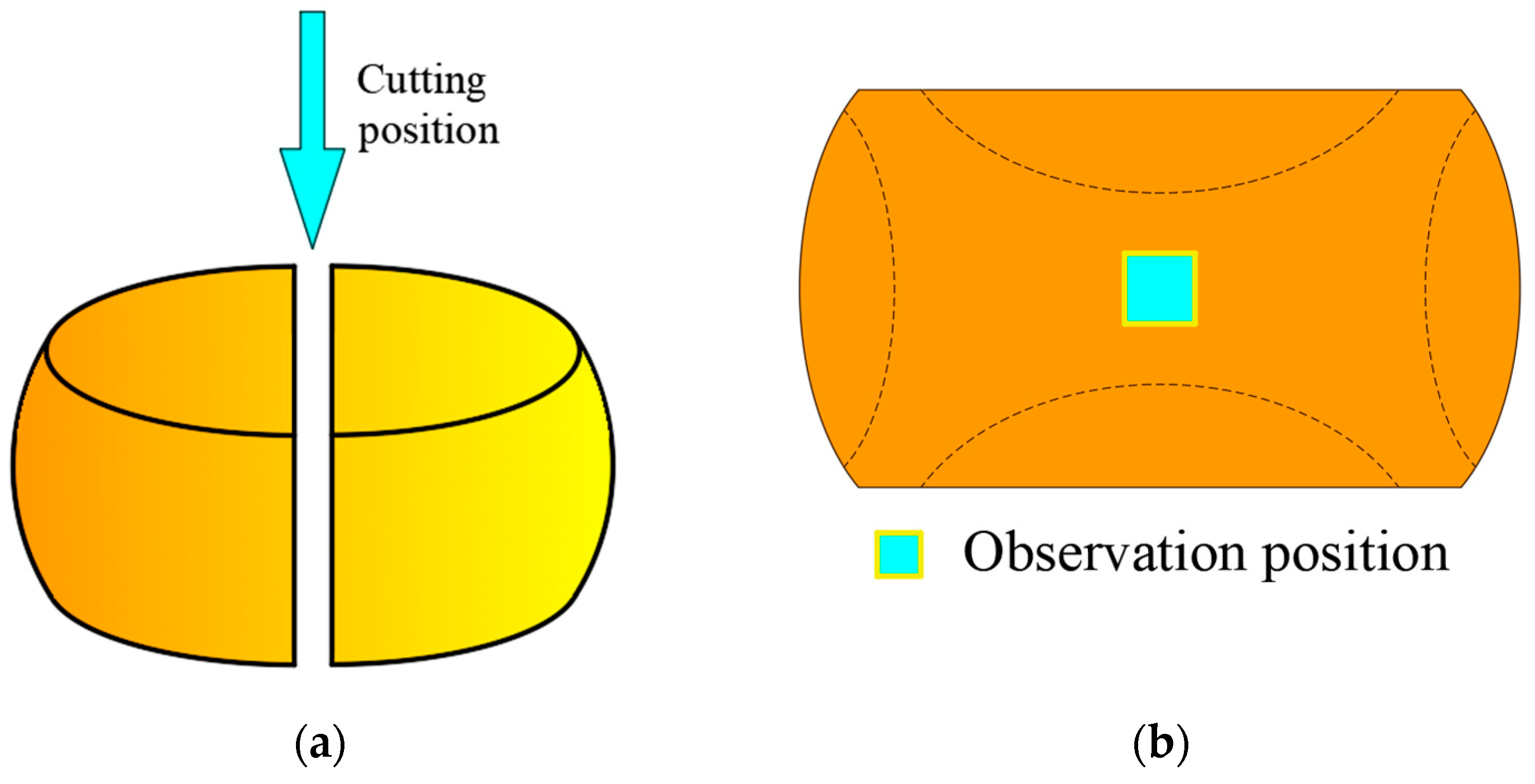
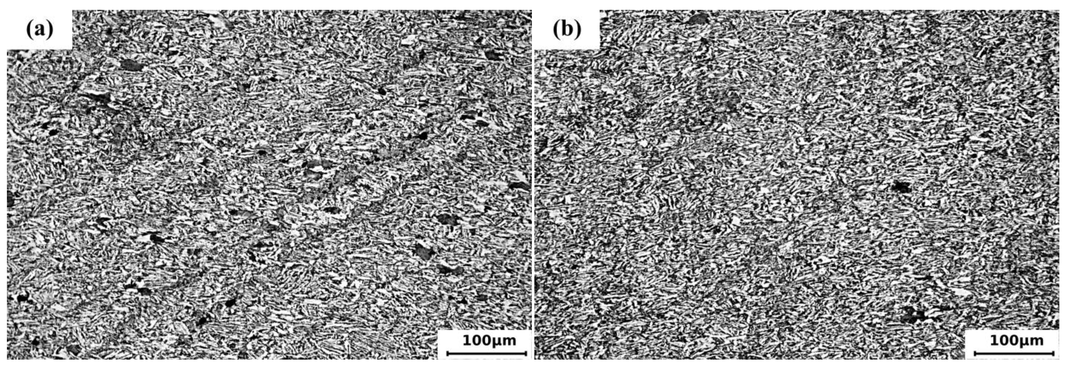
3.1.3. Influence of Upsetting Parameters on Microstructure

Figure 5a–e shows the optical microstructure of the original 42CrMo sample and strain rate 1 s−1, deformation temperature of 20 °C, 500 °C, 650 °C, and 800 °C, deformation amount of 60%, respectively. The compression direction is from top to bottom. It can be seen from the figure that the grain size varies significantly with the change in temperature. From Figure 5a, it can be clearly seen that the grains of the original sample have relatively evenly distributed ferrite and bainite structures. After compression at room temperature (20 °C), the grain size was finer than that of the original billet, and the grain size was significantly reduced, as shown in Figure 5b. which is due to the upset force that causes the larger grains to break up and form fine grains [28]. The grain of the sample at 500 °C is further stretched and broken compared with that at 20 °C. However, the sample with a temperature of 650 °C has strip and block grains again, which is due to the upsetting deformation at 650 °C coupled with the deformation temperature rise, and the action of thermal activation makes some dislocation defects disappear or recombine, resulting in the recovery of fine broken grains and some growth. When the sample is compressed and deformed at 800 °C, the grains inside the sample are the smallest and most uniform. This is because the sample is heated to 800 °C, the austenite region above the AC3 temperature of 42CrMo is subjected to rapid compression and deformation, and a fine grain structure is formed after air cooling. However, as can be seen from Figure 5e, due to the phase transformation of the steel during the cooling process after the warm upsetting deformation, the ferrite preferentially extends in the dendrite segregation and non-metallic inclusion and precipitates out in a band along the metal flow direction, resulting in a local band structure [29]. It can be seen that the grain can be refined by upsetting deformation at 500–650 °C, and the grain refinement mechanism is mechanical crushing and refining. When the temperature is slightly higher, the broken grain will recover, and the size will grow.
Figure 5d and Figure 6a,b show the 42CrMo sample at 650 °C; the deformation rate of warm upsetting is 1 s−1, 10 s−1, and 15 s−1, respectively, and the deformation amount is 60%. As can be seen from the figure, the grain size is obviously refined with the increase in strain rate, mainly because the deformation rate is too large. The effect of the mechanical driving force on grain breakage is enhanced. When the strain rate increases, the short deformation time greatly restricts the movement of dislocation, resulting in a rapid increase in dislocation density and further refinement of grains [30].

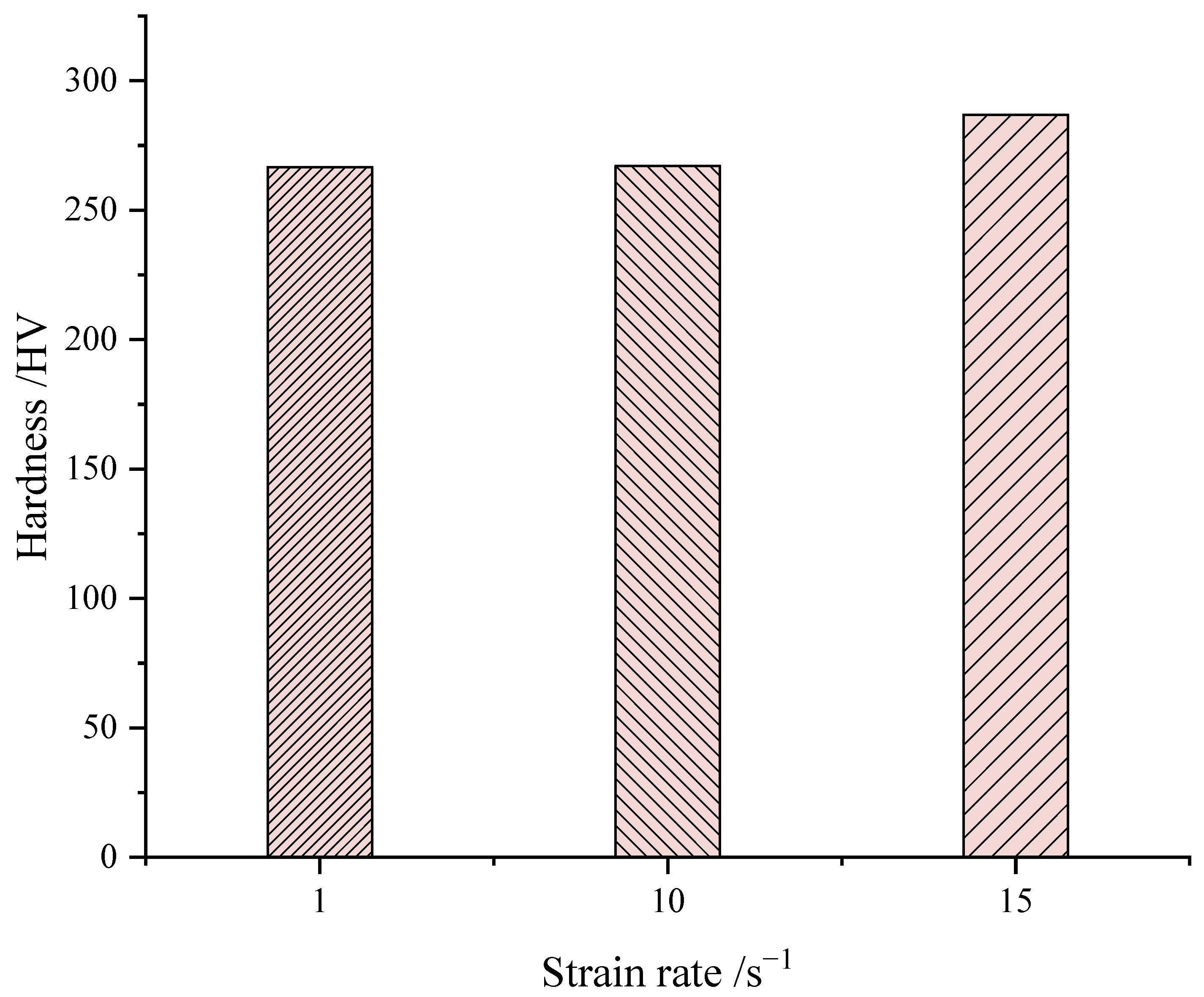
3.1.4. Influence of Strain Rate on Hardness

As shown in Figure 7, Vickers hardness values at 650 °C and different strain rates show that when the temperature is 650 °C, and the strain rate is 1 s−1 and 10 s−1, the hardness values of the samples have little difference, while the hardness values of the samples with a deformation rate of 15 s−1 increase, reaching 286.9 HV, indicating that a higher strain rate can increase the hardness.

3.2. Analysis of Multi-Station Warm Upsetting Experiment Results

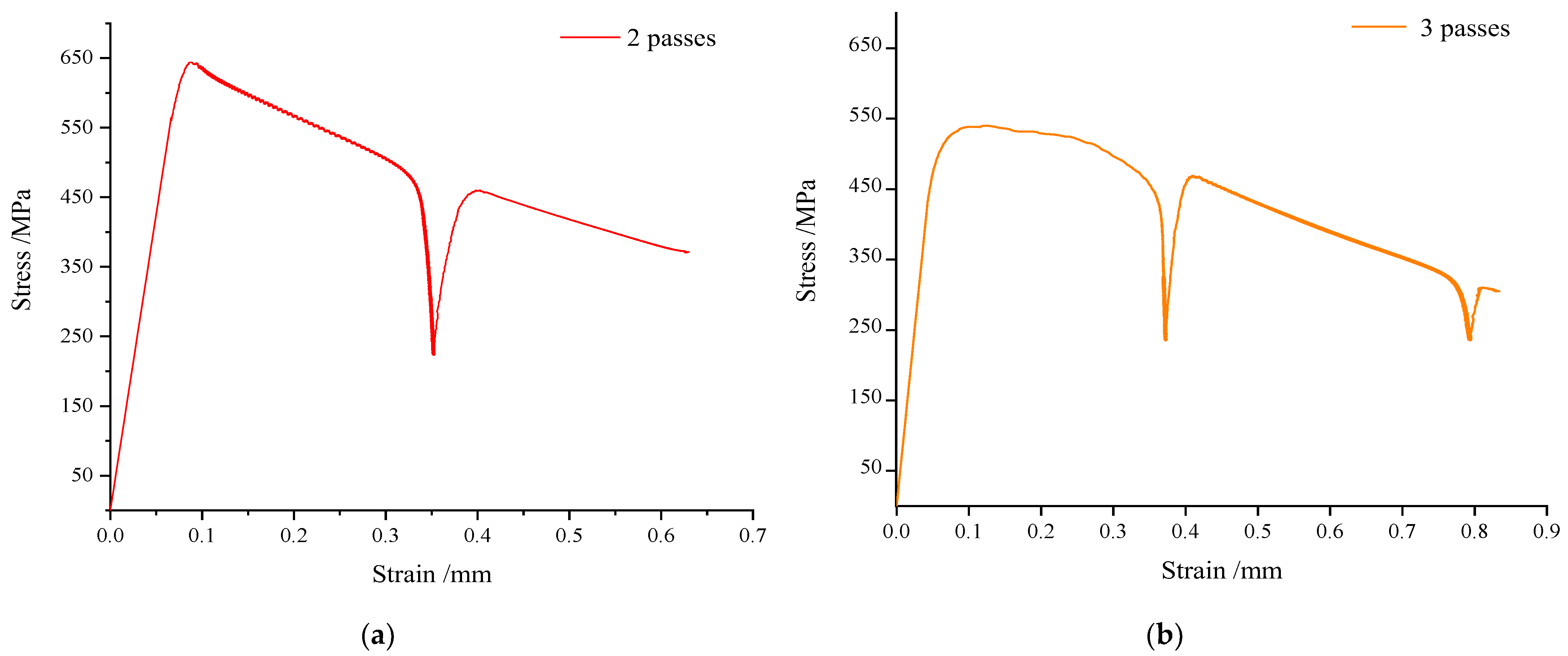
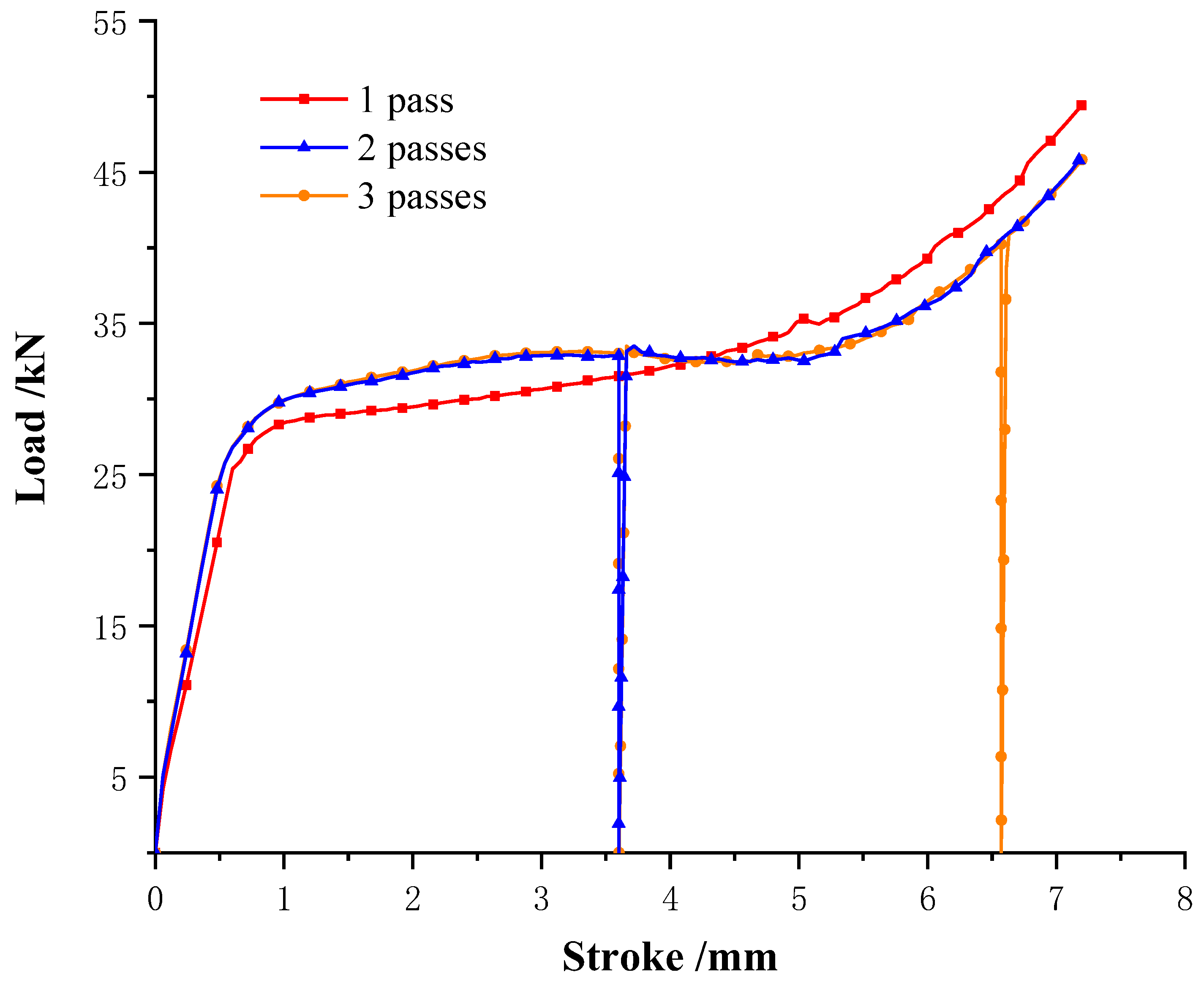
3.2.1. Influence of Passage Number on Stress-Strain Curve of Warm Upsetting Deformation

In order to physically simulate multi-station warm upsetting, a multi-pass compression test was carried out on the bar material. The temperature was set at 650 °C for constant temperature compression, the strain rate was 10 s−1, and the compression deformation of each pass was 30% (3.6 mm) for two passes and 3.6 mm, 2.94 mm, and 2.184 mm for each pass of three passes, respectively. The true stress–strain curve is shown in Figure 8, where the rapid rise and fall of stress is intended to simulate the loading and unloading process between passes. As can be seen from Figure 8, the stress increases first with the increase in strain and then decreases rapidly after reaching the peak stress. In addition, the stress–strain curve transition is relatively smooth when unloading and loading processes are excluded between each pass. It can be seen that the number of deformation channels has little influence on the stress–strain curve of 42CrMo steel under the condition of warm deformation. However, compared with single-pass upsetting with the same deformation conditions, the deformation temperature rise, and softening effect of two–-pass and three-pass upsetting are more obvious in the plastic deformation stage, which is because the multi-pass sample is compressive deformation under the state of heat preservation. During the deformation, the temperature of the sample changes little, and the metal deformation resistance does not increase due to the decrease in temperature, so the softening degree of the sample is relatively good [31].

3.2.2. Microstructure Analysis of Multi-Station Warm Upsetting and Single-Station Warm Upsetting

Figure 9a shows the microstructure of a 42CrMo sample at 650 °C with a deformation rate of 10 s−1 and a deformation amount of 60% for two-pass samples, and Figure 9b shows the internal microstructure of a three-pass sample with a deformation amount of 75%. It can be seen from the figure that the grain size of the two-pass sample is slightly refined compared with that of the single-pass (Figure 6a) sample, but the distribution of ferrite is relatively uniform, indicating that the reduction in fewer passes has less influence on the grain structure. After three passes of compression, the grain structure is obviously refined, mainly because the deformation is highly uneven in the lower temperature range. After multiple upsettings, strong shear deformation of local strip grains is caused, forming fine grains.

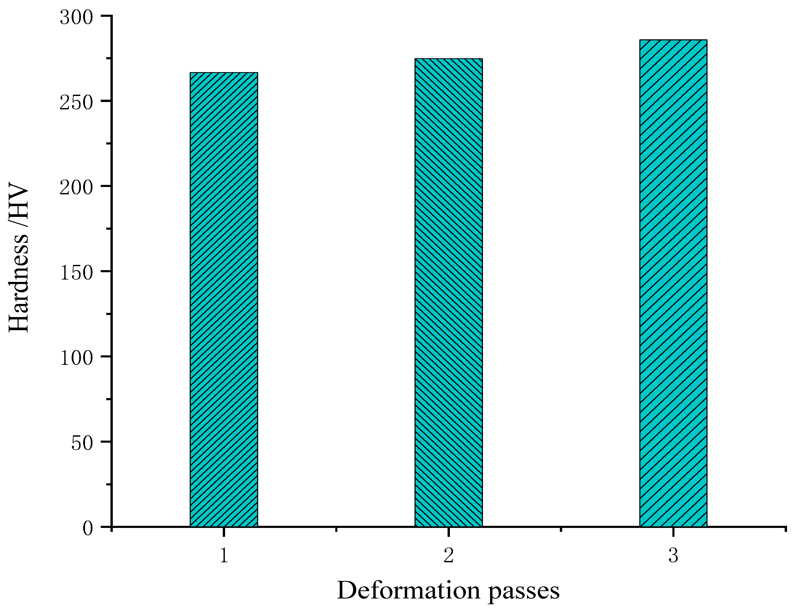
3.2.3. Analysis of Microhardness of Multi-Station and Single-Station Warm Upsetting

Figure 10 shows the Vickers hardness values at 650 °C and the 10 s−1 strain rate under different deformation passes. It can be seen from the figure that deformation passes also have a certain influence on the hardness values. Compared with single-pass, the hardness values of two passes increase slightly, and the hardness values of three passes are the highest, mainly due to the effect of grain refinement, which is consistent with the grain distribution in Figure 6a and Figure 9.

4. Numerical Simulation Analysis of the Warm Upsetting Forming Process of Typical Parts

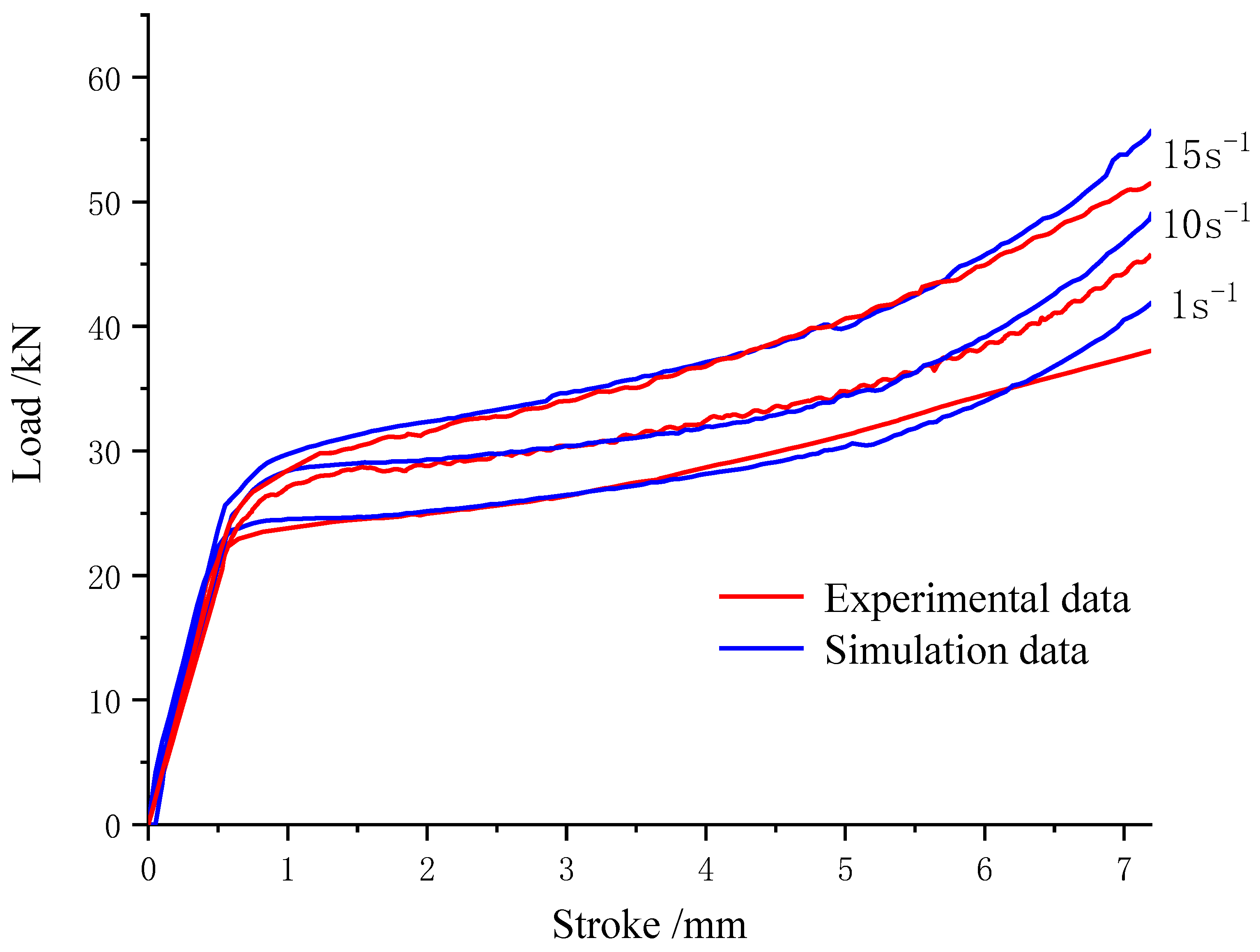
4.1. Comparative Analysis between Numerical Simulation and Experiment of Load-Displacement Curve

Figure 11 shows the stroke-load curve of the simulation experiment at a temperature of 650 °C and a strain rate of 1 s−1, 10 s−1, and 15 s−1. Compared with Figure 11, it is found that the stroke-load curve values obtained by the Deform-3D simulation software are in good agreement with the experimental values. Both experimental data and simulation data show that the load increases sharply at the initial stage of displacement and continues to increase as the displacement continues to increase.
In order to further quantitatively evaluate the accuracy of the simulation value, the correlation coefficient R (Equation (2) between the simulation value and the experimental value and the absolute mean relative error (AARE) (Equation (3) is calculated. The calculated correlation coefficient R is 0.9948, and the average absolute relative error (AARE) is 2.05%. Therefore, the relationship between displacement and applied load can be accurately reflected through simulation.
R = i = 1 N C i C ¯ T i T ¯ i = 1 N C i C ¯ 2 i = 1 N T i T ¯ 2
A A R E = 1 N i = 1 N C i T i / C i
where  C i  and  C ¯  are the load experimental values and average values, respectively; T i  and T ¯ are the simulated load values and average values, respectively.

4.2. Comparative Analysis of Numerical Simulation of Multi-Station Warm Upsetting and Single-Station Warm Upsetting

Figure 12 shows the simulation comparison of stroke-load curves for single-pass and multi-pass at a temperature of 650 °C and a strain rate of 1 s−1. It is found that the stroke–load curves of a single pass are in good agreement with the stroke–load curves of two passes and three passes, and the load difference is small.

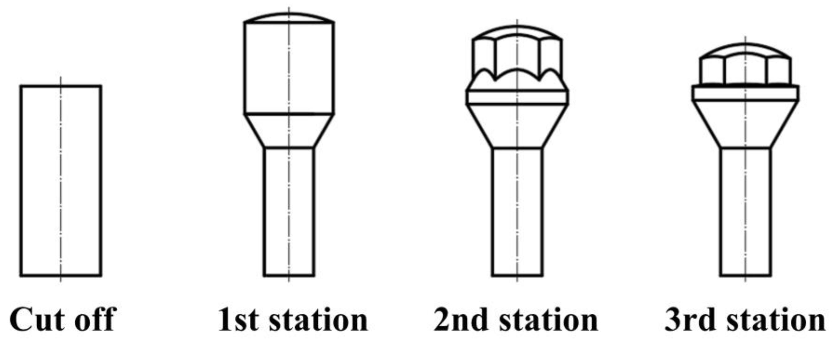
4.3. Warm Upsetting Process Design and Numerical Simulation Conditions for Typical Parts

The process scheme of warm upsetting for automobile tire bolts is shown in Figure 13: The first station is necking; the second station has a hexagonal head and flange pre-upset forming; and the third station flange is finally upset forming. According to the deformation degree equation, the maximum deformation degree of each station is 38.3%, 0.17%, and 2.78%; all of them are less than the allowable deformation degree of 42CrMo material under cold forming, which meets the design requirements.
ε = H 0 H 1 H 0 × 100 %
where ε is the deformation amount, H 0 is the original height of the blank before upsetting, H 1 is the height of the part after upsetting.
The process of the above design was verified by finite element numerical simulation. The rigid plastic finite element method was used to design the molds of the three stations into an integral part, ignoring the deformation of the molds and the ejector rod. The forming of the typical part requires three sets of dynamic molds and fixed molds, and the dynamic molds and fixed molds are set to have rigid contact. The type of selected element is a tetrahedral element. With the progress of numerical simulation, the mesh is undergoing adaptive repartition. The selected material is 42CrMo, the temperature is 650 °C, and the dynamic and fixed modes are set as rigid bodies without grid division. The moving die moves down at a speed of 84 mm/s, and the fixed die remains static. After completing the formation of one station, the die is replaced, and the formation of subsequent stations is continued until the typical part is fully formed.

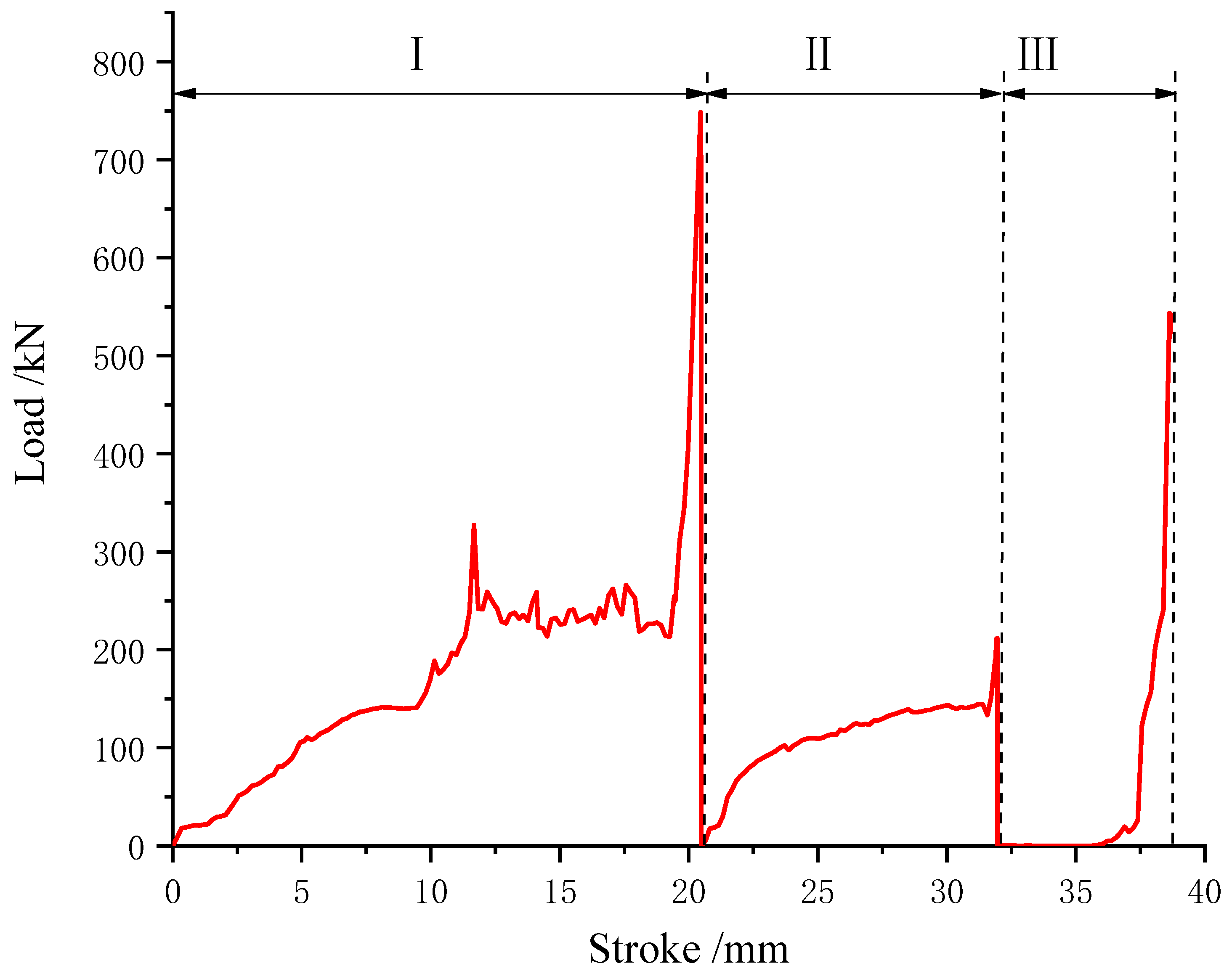
4.4. Analysis of Stroke-Load Curve of Typical Parts under Warm Upsetting

As can be seen from the stroke–load curve in Figure 14, there are three load peaks in the entire deformation process, which increase with the increase in the degree of deformation. The initial load of each station is relatively gentle because, in the initial loading phase, the local deformation increases, while most of the rest do not produce large deformation. With the progress of the loading stage, the load–stroke curve appears to have an upward inflection point, the contact area between the blank and the mold cavity increases, the material enters the stage of compression upsetting, and when the maximum load of the station is reached, the material enters the maximum plastic deformation state of the station, and the forming of the station is finally completed. It can be seen from the figure that the load of the first station is the largest, reaching, followed by the third station, mainly because the deformation of the first station is the largest.

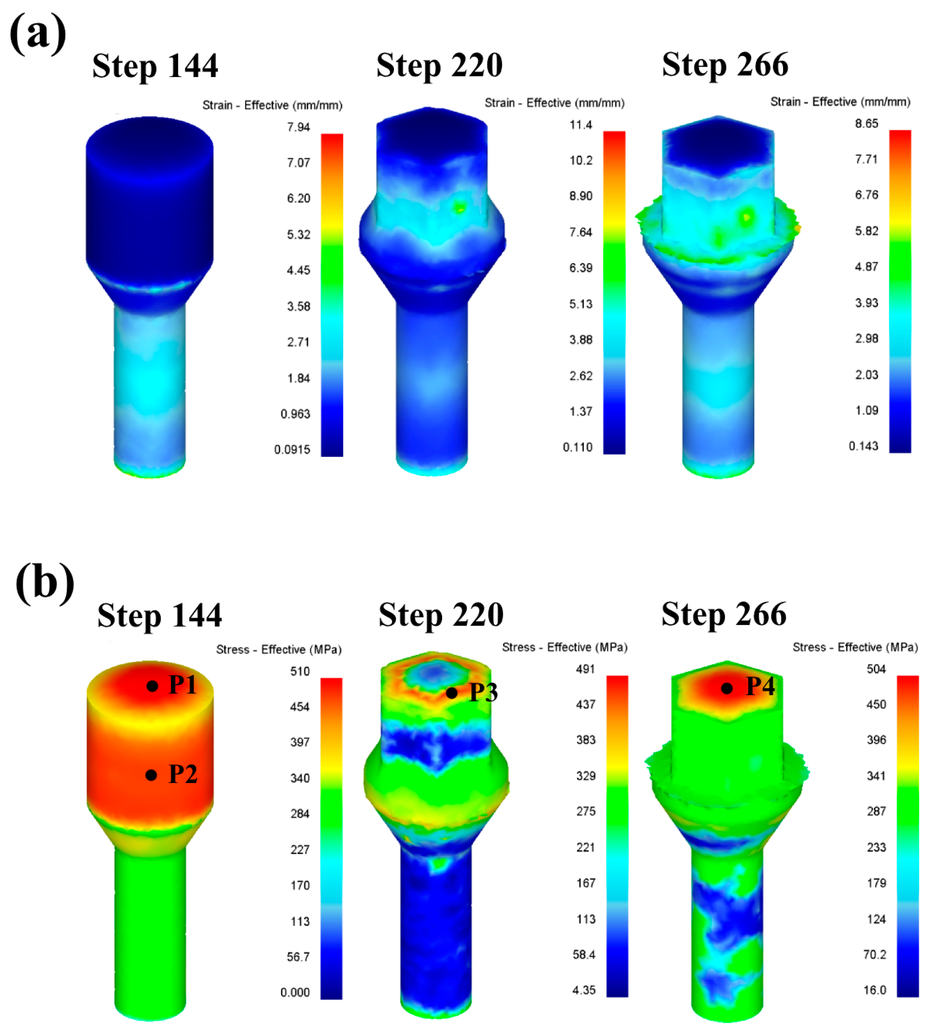
4.5. Stress Nephogram Analysis of the Warm Upsetting of Typical Parts

Figure 15 shows the distribution diagram of equivalent strain and stress after forming at each station. It can be seen from the diagram that the maximum equivalent strain at each station is mainly distributed at the maximum deformation of each station, among which the first station is mainly reduced in diameter, the material at the lower end of the billet is squeezed, the metal flows to the reduced mold cavity, the deformation is large, the contact area between the upper end of the billet and the mold increases, and the friction also increases due to the restriction of the forging mold cavity. Therefore, the deformation stress in the P1 and P2 regions at the upper end of the billet is large, as shown in Figure 15b. The second station is mainly formed for the hexagonal head and flange pre-upsetting. Because the lower end of the hexagonal head and the upper end of the flange are not bound by the mold, the strain is larger. The final forming part of the second station is the arc position of the top of the hexagonal head, and the arc of the top is smaller than that of the first station; the maximum stress distribution position of the top of the hexagonal head is a ring, and the maximum stress point is P3. The third station is the final upsetting stage, and each position has different degrees of deformation, among which the largest deformation position is the flange, and the equivalent strain value is also the largest. The whole part is completely covered by the mold, which makes the overall stress larger, and the maximum stress point is in the P4 area at the top of the hexagonal head. Due to the relatively complicated deformation of the hexagonal head, there is a flying edge around the hexagonal head when it forms at the third station. Subsequent trimming is required.

5. Conclusions

In this paper, 42CrMo high-strength steel was used as the material. Compression tests with different parameters were carried out on the Gleeble-3500 thermal simulation machine for 42CrMo steel. The influences of different temperatures, strain rates, and deformation passes on microstructure evolution and mechanical properties were studied in detail, and the warm upsetting forming of typical parts was simulated.
(1)
In rapid upsetting deformation, with the increase in deformation temperature, the kinetic energy between atoms increases, the binding force decreases, and the dislocation is easier to overcome the pinning effect and move, resulting in a temperature rise softening effect that significantly reduces the peak flow stress. In addition, the maximum peak flow stress of 42CrMo steel is only 45.3% of the cold upsetting deformation at room temperature when it deforms at about 650 °C. In the plastic deformation stage, the stress-strain curve tends to be gentle, and it is in the best state of warm deformation;
(2)
42CrMo steel at 500–650 °C warm upsetting deformation conditions, the internal grain structure is significantly refined, and the grain refinement mechanism is mechanical crushing refinement. At slightly higher temperatures, the broken grain recovery and grain size grow;
(3)
The correlation coefficient R and the absolute value of average relative error (AARE) between the simulated value and the experimental value were calculated through Deform. The obtained correlation coefficient R is 0.9948, and the average absolute relative error (AARE) is 2.05%, indicating that the simulation can accurately reflect the relationship between displacement and applied load.

Author Contributions

Z.X. carried out the concept, methodology, and writing the first draft. H.W. carried out the formal analysis, wrote the manuscript, and performed the data analysis. J.L. carried out a formal analysis and provided experimental instruments and data processing. J.J. mainly performed the investigation and verification. L.Y. carried out the concept, methodology, and guide on experimental design. Y.Z. undertook originality and form analysis. All authors have read and agreed to the published version of the manuscript.

Funding

This work was supported by the Henan Province Science and Technology Research Project (222102230118) and the Key Research Projects of Higher Education Institutions in Henan Province (23A460016).

Data Availability Statement

The raw data supporting the conclusions of this article will be made available by the authors on request.

Conflicts of Interest

Author Jinhua Liu was employed by the Sijin Intelligent Forming Machinery Company Limited Co., Ltd. The remaining authors declare that the research was conducted in the absence of any commercial or financial relationships that could be construed as a potential conflict of interest.

References

  1. Khanawapee, U.; Butdee, S. A study of barreling and DEFORM 3D simulation in cold upsetting of bi-material. Mater. Today 2020, 26, 1262–1270. [Google Scholar] [CrossRef]
  2. Filipov, A.A.; Pachurin, G.V.; Goncharova, D.A.; Nuzhdina, T.V.; Mukhina, M.V.; Katkova, O.V.; Matveev, U.I.; Tsapina, T.N. Structural and mechanical maintenance of quality of the rolled stock for cold upsetting of metal articles. IOP Conf. Ser. Mater. Sci. Eng. 2019, 632, 012010. [Google Scholar] [CrossRef]
  3. Pachurin, G.V.; Shevchenko, S.M.; Filippov, A.A.; Mukhina, M.V.; Kuzmin, N.A. March. Defining rolled metal performance for cold bolt upsetting (bolt head). IOP Conf. Ser. Mater. Sci. Eng. 2018, 327, 032040. [Google Scholar] [CrossRef]
  4. Sweet, G.A.W.; Williams, B.W.; Taylor, A.; Hexemer, R.L.; Donaldson, I.W.; Bishop, D.P. A microstructural and mechanical property investigation of a hot upset forged 2xxx series aluminum powder metallurgy alloy reinforced with AlN. J. Mater. Process Technol. 2020, 284, 116742. [Google Scholar] [CrossRef]
  5. Li, S.; Ji, H.; Wang, B.; Mu, Y. Numerical analysis and experimental validation of conjunction gear via hot forging-upsetting finishing-radial extrusion. Arch. Civ. Mech. Eng. 2019, 19, 391–404. [Google Scholar] [CrossRef]
  6. Arulmani, L.; Shridharmurthy, H.N.; Selvan, M.C.P.; Madara, S.R. Hot powder forging behavior analysis of sintered AISI 8740 PM steels for automotive application. Mater. Today 2020, 28, 1068–1072. [Google Scholar] [CrossRef]
  7. Lu, Y.; Zhu, Z.; Li, D.; Xie, Q. Constitutive model of 42CrMo steel under a wide range of strain rates based on crystal plasticity theory. Mater. Sci. Eng. A 2017, 679, 215–222. [Google Scholar] [CrossRef]
  8. Zhang, J.; Liu, Z.; Sun, J.; Zhao, H.; Shi, Q.; Ma, D. Microstructure and mechanical property of electropulsing tempered ultrafine grained 42CrMo steel. Mater. Sci. Eng. A 2020, 782, 139213. [Google Scholar] [CrossRef]
  9. Qi, K.; Yang, Y.; Hu, G.; Lu, X.; Li, J. Thermal expansion control of composite coatings on 42CrMo by laser cladding. Surf. Coat. Technol. 2020, 397, 125983. [Google Scholar] [CrossRef]
  10. Ji, H.; Duan, H.; Li, Y.; Li, W.; Huang, X.; Pei, W.; Lu, Y. Optimization the working parameters of as-forged 42CrMo steel by constitutive equation-dynamic recrystallization equation and processing maps. J. Mater. Sci. Technol. 2020, 9, 7210–7224. [Google Scholar] [CrossRef]
  11. Liu, H.; Cheng, Z.; Yu, W.; Wang, G.; Zhou, J.; Cai, Q. Deformation behavior and constitutive equation of 42crmo steel at high temperature. Metals 2021, 11, 1614. [Google Scholar] [CrossRef]
  12. Zhu, S.; Peng, W.; Shu, X. Effect of tempering on bonding characteristics of cross wedge rolling 42CrMo/Q235 laminated shafts. J. Iron Steel Res. 2020, 27, 1170–1178. [Google Scholar] [CrossRef]
  13. Qin, F.; Qi, H.; Liu, C.; Qi, H.; Meng, Z. Constitutive Characteristics, Microstructure, and Texture Evolution of As-Cast 42CrMo Alloy in Nonisothermal Multipass Compression. Adv. Mater. Sci. Eng. 2021, 2021, 6638505. [Google Scholar] [CrossRef]
  14. Wu, Z.; Peng, W.; Shu, X. Influence of rolling temperature on interface properties of the cross wedge rolling of 42CrMo/Q235 laminated shaft. Int. J. Adv. Manuf. Technol. 2017, 91, 517–526. [Google Scholar] [CrossRef]
  15. Ji, H.; Wang, J.; Wang, Z.; Li, Y.; Cheng, X. The effect of high-temperature ECAP on dynamic recrystallization behavior and material strength of 42CrMo steel. Mater. Sci. Eng. A 2023, 887, 145732. [Google Scholar] [CrossRef]
  16. Lin, Y.; Chen, M.; Zhong, J. Effect of temperature and strain rate on the compressive deformation behavior of 42CrMo steel. J. Mater. Process. Technol. 2008, 205, 308–315. [Google Scholar] [CrossRef]
  17. Qian, D.; MA, B.; Deng, J. Numerical simulation and experimental study on grain evolution in whole process of forging and rolling forming-waste heat quenching of 42CrMo ring. J. Plast. Eng. 2022, 29, 110–117. [Google Scholar]
  18. Wang, B.; Shi, J.; Ye, P.; Deng, L.; Wang, C.; Chen, J.; Li, Q. In-situ investigation on nucleation and propagation of {10–12} twins during uniaxial multi-pass compression in an extruded AZ31 Mg alloy. Mater. Sci. Eng. A 2018, 731, 71–79. [Google Scholar] [CrossRef]
  19. Hu, Z.; Zhou, X.; Nie, X.; Zhao, S.; Liu, H.; Yi, D.; Zhang, X. Finer subgrain microstructure induced by multi-pass compression in α + β phase region in a near-β Ti-5Al-5Mo-5V-1Cr-1Fe alloy. J. Alloys Compd. 2019, 788, 136–147. [Google Scholar] [CrossRef]
  20. Yan, Z.; Liu, H.; Dai, X.; Li, L.; Zhang, Z.; Wang, Q.; Xue, Y. Effect of multi-pass cooling compression and subsequent heat treatment on microstructural and mechanical evolution of TC4 alloys. J. Mater. Sci. Technol. 2023, 23, 3137–3150. [Google Scholar] [CrossRef]
  21. Hou, H.; Zhao, G.; Yu, J.; Wei, D. Nonlinear unloading-reloading behavior and macro/micro models during multi-pass cyclic hot compression of aluminum alloys. Mater. Sci. Eng. A 2023, 882, 145447. [Google Scholar] [CrossRef]
  22. Qin, F.; Li, Y.; Qi, H.; Lv, Z. Deformation behavior and microstructure evolution of as-cast 42CrMo alloy in isothermal and non-isothermal compression. J. Mater. Eng. Perform. 2016, 25, 5040–5048. [Google Scholar] [CrossRef]
  23. Huang, W.; Zhong, H.; Lei, L.; Fang, G. Microstructure and mechanical properties of multi-pass forged and annealed 42CrMo steel. Mater. Sci. Eng. A 2022, 831, 142191. [Google Scholar] [CrossRef]
  24. Zhu, Q.; Lei, L.; Ban, C.; Zhao, Z.; Zuo, Y.; Cui, J. Structure uniformity and limits of grain refinement of high purity aluminum during multi-directional forging process at room temperature. Trans. Nonferrous Met. Soc. China. 2014, 24, 1301–1306. [Google Scholar] [CrossRef]
  25. Liu, Z. Study on Microstructures, Mechanical Properties and Cold Forming of TC16 Titanium Alloy Bars; Jiangsu University: Zhenjiang, China, 2021. [Google Scholar]
  26. Zhai, C.; Feng, C.; Chai, L.; Lu, Z.; Nie, Z.; Chen, Z. Study on X2A66 rheological deformation behavior of aluminum-lithium alloy during isothermal compression. Rare Met. Mater. Eng. 2017, 46, 90–96. [Google Scholar]
  27. Chen, Y.; Qi, H.; Li, Y.; Pang, X. Modification of constitutive model and evolution of activation energy for forged 42CrMo steel during high temperature deformation process. Forg. Stamp. Technol. 2021, 46, 260–269. [Google Scholar]
  28. Xiao, Z. Research on Mechanism of Multi-Stage Cold Forging and Optimum Structure of Machine; China Academy of Machinery Science and Technology: Beijing, China, 2015. [Google Scholar]
  29. Yan, P.; Yan, Z. Improvement method of defect structure in forging steel. Phys. Testing Chem. Anal. Part A (Phy Test) 2023, 59, 28–31. [Google Scholar]
  30. Huang, F.; Zhong, F.; Li, P.; Liang, Y. Influence factors on grain deformation and refinement mechanisms during plastic deformation. Foundry Technol. 2011, 32, 1602–1605. [Google Scholar]
  31. Hu, B.; Zhang, B.; Wei, C.; Zhang, Z. Influence of die preheating temperature and punch working speed on quality of roller formed cylinder. J. Plast. Eng. 2020, 27, 47–52. [Google Scholar]
Figure 1. Experimental equipment and flow chart: (a) Gleeble-3500 thermal simulation testing machine; (b) IE500M metallographic microscope; (c) 430SVA Vickers hardness tester.
Metals 14 00135 g001
Figure 2. Cutting position and metallographic observation position of the sample: (a) cutting position diagram; (b) observation position diagram.
Metals 14 00135 g002
Figure 3. Stress–strain curves at different deformation temperatures with a strain rate of 1 s−1.
Metals 14 00135 g003
Figure 4. Stress–strain curves at different strain rates at 650 °C.
Metals 14 00135 g004
Figure 5. Grain morphology at different temperatures: (a) original sample; (b) 20 °C; (c) 500 °C; (d) 650 °C; (e) 800 °C.
Metals 14 00135 g005
Figure 6. Grain morphology at different strain rates: (a) 10 s−1; (b) 15 s−1.
Metals 14 00135 g006
Figure 7. Vickers hardness at different strain rates.
Metals 14 00135 g007
Figure 8. Multi-pass stress-strain curve: (a) two passes; (b) three passes.
Metals 14 00135 g008
Figure 9. Grain morphology with different pass times: (a) two passes; (b) three passes.
Metals 14 00135 g009
Figure 10. Vickers hardness of different deformation passes.
Metals 14 00135 g010
Figure 11. Stroke–load curve at 650 °C.
Metals 14 00135 g011
Figure 12. Simulation comparison of single-pass and multi-pass stroke–load curves.
Metals 14 00135 g012
Figure 13. Typical bolt warm upsetting process scheme.
Metals 14 00135 g013
Figure 14. Stroke–load curve of each station.
Metals 14 00135 g014
Figure 15. Equivalent stress and strain distribution: (a) equivalent strain; (b) equivalent stress.
Metals 14 00135 g015
Table 1. Comparison test scheme of cold upsetting and warm upsetting.
Deformation Temperature (°C)Strain Rate (s−1)Deformation Amount (%)
20160
500160
650160
800160
6501060
6501560
Table 2. Multi-pass warm upsetting test scheme.
Total Number of DeformationNumber of DeformationDeformation Amount (mm)Strain Rate (s−1)Deformation Temperature (°C)
213.610650
23.610650
313.610650
22.9410650
32.18410650
Disclaimer/Publisher’s Note: The statements, opinions and data contained in all publications are solely those of the individual author(s) and contributor(s) and not of MDPI and/or the editor(s). MDPI and/or the editor(s) disclaim responsibility for any injury to people or property resulting from any ideas, methods, instructions or products referred to in the content.

