Article

Investigation of the Flow Stress Model for Cr4Mo4V Bearing Steel under Ultrasonic Vibration Conditions

1
School of Mechanical and Automotive Engineering, Shanghai University of Engineering Science, Shanghai 201620, China
2
Key Laboratory of Intelligent Manufacturing Technology for Large Complex Thin-Walled Parts of Aviation for Machinery Industry, Shanghai 201620, China
3
Sichuan Research Institute, Shanghai Jiao Tong University, Chengdu 610213, China
4
Chengdu Zhiyuan Advanced Manufacturing Technology Research Institute, Chengdu 610000, China
5
School of Mechanical Engineering, Georgia Institute of Technology, North Ave NW, Atlanta, GA 30332, USA
*
Author to whom correspondence should be addressed.
Metals 2024, 14(2), 143; https://doi.org/10.3390/met14020143
Submission received: 9 December 2023 / Revised: 17 January 2024 / Accepted: 18 January 2024 / Published: 24 January 2024

Abstract

:
To investigate the mechanisms behind the effect of ultrasonic vibration on the plastic deformation of materials, the flow stress model of Cr4Mo4V was established according to the dislocation dynamics and thermal activation theory, which considers the effect of dislocation density evolution on plastic deformation under ultrasonic vibration conditions. The effect of amplitude and strain rate on the flow stress was analyzed by fitting the stress-strain data obtained from an ultrasonic vibration-assisted tensile (UVAT) single-factor test. To investigate the influence of strain rate and vibration duration on the acoustic effect, comparative tests with and without vibration were performed for various strain rates. The results showed that the flow stress decreased significantly in the tensile test with ultrasound compared to the test without ultrasound, and the degree of reduction increased with increasing amplitude. In addition, the nonlinear relationship between the acoustic softening effect and the strain rate was analyzed. The result demonstrates that the dislocation density absorbs the ultrasonic vibration energy, which results in slip and proliferation. Macroscopically, due to a greater susceptibility to plastic deformation, the dislocation density shows residual hardening at the end of the ultrasound. Finally, the average absolute relative error (AARE) between predicted flow stresses and experimental results under three ultrasonic conditions using the developed model were 4.49%, 1.27%, and 5.64%, which proved the validity of the model.

1. Introduction

Aviation bearings are required to work under high temperatures, high pressure, and other complex environments [1]. According to ISO 281 [2], the equivalent load of high-temperature bearing steel can be expressed in terms of the C/P(307.6) value, and the bearing life can then be calculated using this concept [3]. To improve properties such as surface quality and fatigue life of the bearing, the processes of rolling [4], forging [5], heat treatment [6], and special machining are commonly used. However, the bearing steel has high deformation resistance, low plasticity, and poor forming and machining properties. During machining, high-strength materials require higher true loads and are more prone to crack formation, which suggests that good surface quality is not easily obtained. Recently, researchers have developed many assisted machining processes. The thermal effect produced through the use of laser, plasma, and electric pulses can improve the plastic deformation capacity of the workpiece, but it is difficult to accurately control the heating temperature. Cooling media such as liquid nitrogen can be used to reduce the processing temperature, but it will increase the residual stress of the workpiece [7]. In that regard, ultrasonic vibration superimposition on the conventional process is a more competitive technology [8]. Numerous experiments show that ultrasonic vibration can significantly improve the surface quality of parts. The high-frequency vibrations induce kinematic changes and thermal effects [9,10], which play an important role in ultrasonic vibration-assisted machining and ultrasonic welding. Furthermore, high-frequency vibration reduces the flow stress of the material, which makes the metallic material more susceptible to plastic deformation [11,12].
The mechanisms of material softening under ultrasonic action are considered to be surface effects and volume effects [13]. Blaha and Langenecker [14] first found that the flow stress was reduced by superimposed vibrations during the stretching of zinc. Wang et al. [15] conducted an ultrasonic vibration tensile test on pure titanium and observed that the flow stress decreased immediately after the application of vibration and the degree of decrease increased with the increase of acoustic energy density. Cao et al. [11] carried out ultrasonic vibration upsetting experiments on 6061 aluminum alloy and found that the temperature change during the experiment was minimal and the temperature had little effect on the flow stress reduction during compression. Kang et al. [16] performed micro tensile experiments on pure copper and found that ultrasonic vibration in the elastic phase had little effect on the flow stress. Huang et al. [17] conducted ultrasonic vibration experiments on pure polycrystalline copper and found that ultrasonic residual softening occurred after ultrasonic unloading and increased with ultrasonic energy. Yao et al. [12] found that aluminum has both residual softening and residual hardening under ultrasonic energy fields. Zheng et al. [18] conducted ultrasonic vibration stretching on a magnesium alloy plate, which showed that softening plays a dominant role when the amplitude is small, and hardening plays a dominant role when the amplitude increases to a certain degree.
The above studies have focused on light alloys and pure metals; these metals are categorized as low-strength deformable materials [19]. In addition, the crystal structures of the main components of these metals are face-centered cubic (FCC) and hexagonal compact (HCP) stacking [20]. Dutta et al. [21] performed ultrasonic vibration tensile tests on low-carbon steel and observed a significant reduction in sub-crystals in the stretched specimens. The main component of low-carbon steel is ferrite, which is a body-centered cubic (BCC) structure, while the study showed an increase in sub-crystallization in FCC aluminum samples subjected to ultrasonic excitation [22], with opposite results observed for the two materials under ultrasonic conditions. Therefore, various crystal structures do not behave similarly under ultrasonic vibrations. The plastic deformation mechanism of the material becomes more complex under the ultrasonic energy field. Several researchers have conducted studies on its model and mechanism [11,12,23,24], which focused on the deformation mechanisms of FCC and HCP materials with ultrasonic vibrations, and the corresponding physical models developed, with few differences in crystal structures taken into account.
Recently, several studies have explored the acoustic plasticity of higher-strength metallic materials [25,26]. However, the acoustic plasticity and its models for high-strength steels are currently uncommon. In this paper, ultrasonic vibration tensile experiments were conducted on Cr4Mo4V bearing steel to investigate the effects of amplitude and strain rate on flow stresses. Cr4Mo4V is a kind of bearing steel with high strength, which has a ferrite matrix with BCC crystal structure and carbides with FCC crystal structure [27]. The acoustic–plastic behavior of bearing steel under ultrasonic vibration conditions has been less studied, and few corresponding acoustic-plastic models are available. The material flow stress is an important reference quantity for the machining process, and it is necessary to understand the mechanism and develop the corresponding model. Based on the thermal activation theory and dislocation dynamics, the constitutive flow stress model of Cr4Mo4V bearing steel under ultrasonic vibration was developed by considering the dislocation mechanism of BCC and FCC crystal structure materials. This model provides a reliable theoretical basis to analyze the deformation behavior of the material under the ultrasonic vibration process.

2. Analytical Models

2.1. Classical Crystal Plasticity Theory

The plastic deformation of metals is explained at the microscopic level by dislocations and twinning, and there are significant differences in the dislocation mechanisms of different crystal structures [28]. The dislocation mechanism of FCC metals is the necessity to cross the obstacles formed by forest dislocations; therefore, their thermal activation area depends strongly on the strain, and their flow stress is mainly influenced by strain hardening. The main dislocation mechanism of BCC metals is to overcome the obstacles caused by Peire-Nabarro internal stress; their thermal activation area is independent of strain, and their yield stress is mainly affected by the strain rate effect and temperature effect [29]. Since the magnitude of the flow stress essentially corresponds to the performance of the material in impeding dislocation movement, it is classified as [30]:
σ = σ a + σ t h
where σ a is the athermal term reflecting the long-range barriers unrelated to thermal activation and σ t h is the thermal stress term reacting to the short-range barriers related to thermal activation. The Mechanical Threshold Stress (MTS), which refers to the stress in an absolute zero environment, is also classified as [31]:
σ ^ = σ ^ a + σ ^ t h
where σ ^ a is the athermal stress threshold and σ ^ t h is the thermal stress threshold. The thermal stress is at its maximum at absolute zero. Thermal energy contributes to overcoming the potential barrier as the temperature increases and the thermal stress decreases, while the athermal stress remains unchanged. The flow stress is expressed as [29]:
σ = σ ^ a + f ε ˙ , T σ ^ t h
where f ε ˙ , T is the influence factor describing the strain rate and temperature effect. f ε ˙ , T is expressed as:
f ε ˙ , T = σ t h σ ^ t h = 1 k T G 0 ln ε ˙ ε ˙ 0 1 q 1 p
where k is the Boltzmann constant, T is the absolute temperature, and G 0 = g 0 μ b 3 , the reference activation energy, where g 0 is the nominal activation energy and ε ˙ 0 is the reference strain rate. p and q are a pair of associated parameters that determine the shape of the potential barrier, with p = q = 1 in this paper [12].
For FCC metals, strain hardening is influenced by temperature and strain rate, which is considered in the following constitutive model. The threshold value of the thermal stress term ( σ ^ t h 1 ) for FCC materials is:
σ ^ t h 1 = Y ^ ε n 1 exp k T a 0 μ b 3 ln ε ˙ ε ˙ s 0
where ε is strain, a 0 is the nominal activation energy for saturation reference, ε s 0 is the strain rate for saturation reference, Y ^ is the referenced thermal stress, and n 1 is the strain hardening exponent. The athermal stress threshold ( σ a 1 ) of FCC is:
σ a 1 = M α μ b ρ + K H P d 0
where M is the Taylor factor, α is a parameter close to 1/3, u is Young’s modulus, b is the Burgers vector, ρ is the dislocation density, K H P is the Hall-Petch constant, and d 0 is the initial grain size. After the material has been determined, K H P / d 0 can be temporarily regarded as a constant σ 0 .
The saturation threshold is the reference value at absolute zero, the thermal stress term is maximum, and the athermal stress term is neglected. With regard to BCC metal, given that the thermal stress of the BCC metal is independent of the strain [32], the BCC thermal stress threshold ( σ ^ t h 2 ) is expressed according to Equation (5) as:
σ ^ t h 2 = σ ^ t h 0 exp k T a 0 μ b 3 ln ε ˙ ε ˙ s 0
where σ ^ t h 0 is the reference threshold thermal stress, the magnitude of which is related to the initial microstructure and considered constant once the material is determined. In the constitutive model of BCC metal, the athermal stress term reflects strain-hardening, with strain rate and temperature effects being uncoupled. The athermal stress threshold ( σ a 2 ) is expressed as:
σ a 2 = M α μ b ρ + K H P d 0 + K ε n
The term K ε n is the strain hardening term, which generally takes the form of a power function. K is the strain hardening coefficient, and n is the strain hardening index. The dislocation density evolves during the plastic deformation. One of the typical forms of the dislocation evolution law is [33]:
d ρ d γ = k 1 ρ k 2 ρ
where k 1 and k 2 are the coefficients of dislocation storage and annihilation, respectively.
Equations (1)–(9) provide a constitutive model governing the relationship between the flow stress σ and the normal plastic strain ε . To make the equation concise, it will be represented by c 1 = k / a 0 μ b 3 , c 2 = k / g 0 μ b 3 .

2.2. Athermal Stress Term under the Acoustic Effect

Acoustical effects are usually divided into two aspects: surface effects and volume effects; volume effects include stress superposition and acoustic softening. The acoustic softening is the main mechanism of load drop, which is revealed by the reduction of critical shear stress and the evolution of dislocation density. The critical shear stress depends on the interaction of lattice defects (e.g., dislocations, vacancies, etc.), and the acoustic energy is absorbed by the lattice defects. With the reduction of lattice defects due to ultrasonic effects, the critical shear stress becomes smaller until the ultrasound stops. Meanwhile, ultrasonic vibrations induce the evolution of the dislocation density, which leads to a permanent change in flow stress [12,34].
The variation of flow stresses induced by ultrasonic vibrations comes partly from the dislocation density. Thus, the evolution of dislocations in the acoustic field is expressed as:
d ρ d γ = k 1 1 + η k 1 ρ k 2 1 + η k 2 ρ
By combining the Taylor factor model M = σ / τ = γ / ε and integrating the above equation, the following equation is obtained:
ρ = M k 2 1 + η k 2 k 1 1 + η k 1 C exp k 2 1 + η k 2 2 ε
where the non-dimensional parameters η k 1 and η k 2 are the change ratios of k 1 and k 2 due to the exposure in the acoustic field, respectively. Physically, η k 1 and η k 2 are related to the proliferation and annihilation of additional dislocations induced by ultrasonic vibrations, respectively. Considering the crystal structure of Cr4Mo4V, the matrix is BCC crystal and the carbide is FCC crystal, while the nature of strain hardening is dislocation density evolution. By combining Equations (6), (8) and (11), the athermal stress term under ultrasonic vibration is expressed as:
σ a u = M 2 α μ b k 2 1 + η k 2 k 1 1 + η k 1 C exp k 2 1 + η k 2 2 ε + σ 0

2.3. Thermal Stress Term under the Acoustic Effect

Considering the effect of ultrasonic vibration, the valved thermal stress is attributed to the effect of strain rate, temperature, and acoustics, which is described as f ε ˙ , T , E , with E as the acoustic energy density [24] as described below:
E = 4 π 2 f 2 A 2 ρ m
where f is the frequency, A is the vibration amplitude, and ρ m is the material density. Yao et al. [12] proposed the stress reduction rate, which is generalized to the thermal stress reduction rate λ :
Δ λ = σ t h u σ ^ t h σ t h σ ^ t h = β E σ ^ t h m
where σ t h u is the flow stress under ultrasonic vibration and β and m are parameters to be determined for the experimental study. By combining Equation (4), the influence factor is as follows:
f ε ˙ , T , E = σ t h u σ ^ t h = 1 c 2 T ln ε ˙ ε ˙ 0 β E σ ^ t h m
Given that the crystal structure of Cr4Mo4V includes BCC crystal and the carbide is FCC crystal, the combination of Equations (5) and (7) can be used to obtain the threshold thermal stress( σ ^ t h 3 ) for a mixed crystal structure as follows:
σ ^ t h 3 = l 1 Y ^ ε n 1 exp c 1 T ln ε ˙ ε ˙ s 0 + l 2 σ ^ t h 0 exp c 1 T ln ε ˙ ε ˙ s 0
The thermal stress term ( σ t h u ) under ultrasonic vibration conditions is:
σ t h u = f ε ˙ , T , E l 1 Y ^ ε n 1 exp c 1 T ln ε ˙ ε ˙ s 0 + l 2 σ ^ t h 0 exp c 1 T ln ε ˙ ε ˙ s 0
where l 1 and l 2 are linear constant coefficients, reflecting the proportion of FCC and BCC structural characteristics of Cr4Mo4V bearing steel.
The flow stress model of Cr4Mo4V bearing steel under ultrasonic conditions can be developed by combining Equations (1), (13) and (17). To reduce the number of parameters and linearize the parameters, it can be simplified as follows:
σ u = M 2 α μ b k 2 ( 1 + η k 2 ) k 1 1 + η k 1 C exp k 2 1 + η k 2 2 ε + σ 0 + Y ^ ε n 1 + σ ^ t h 0 exp c 1 T ln ε ˙ ε ˙ s 0 1 c 2 T ln ε ˙ ε ˙ 0 β E σ ^ t h 3 m

3. Experimental Setup

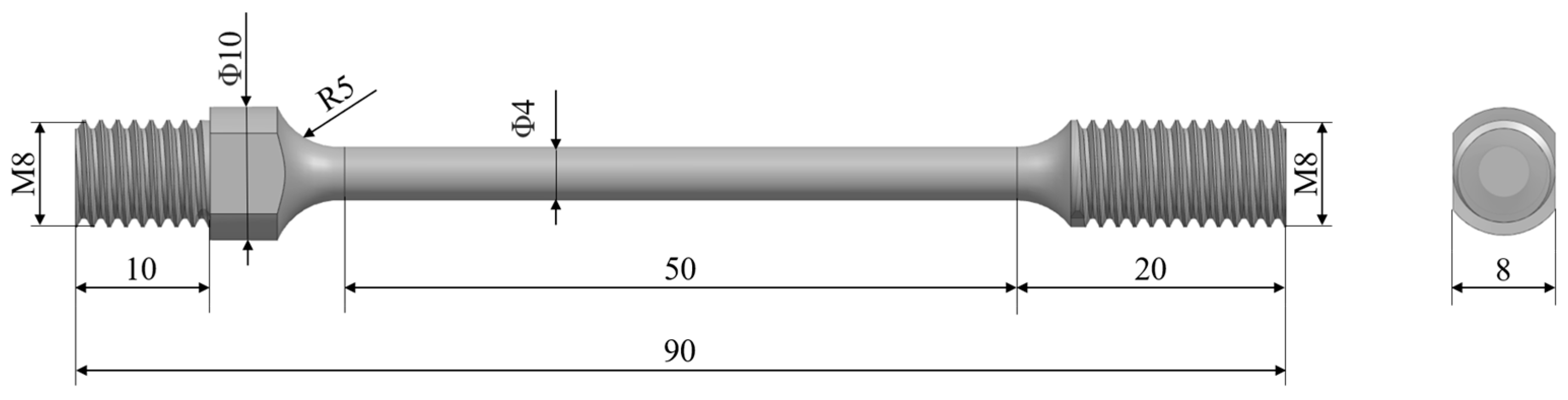
3.1. Sample Preparation

In this paper, the specimens were initially Cr4Mo4V bearing steel plates, whose chemical composition is shown in Table 1, in addition to the M50 bearing steel. According to AMS 6491, it is similar to the M50 bearing steel. They are widely used in aerospace bearing manufacturing [35]. The specimens were prepared by turning with threads at both ends and then grinding the surface of the test section to reduce the roughness. The geometry of the specimen is shown in Figure 1, with the structure easily connected to the variable amplitude horn and well served by the ultrasonic action.

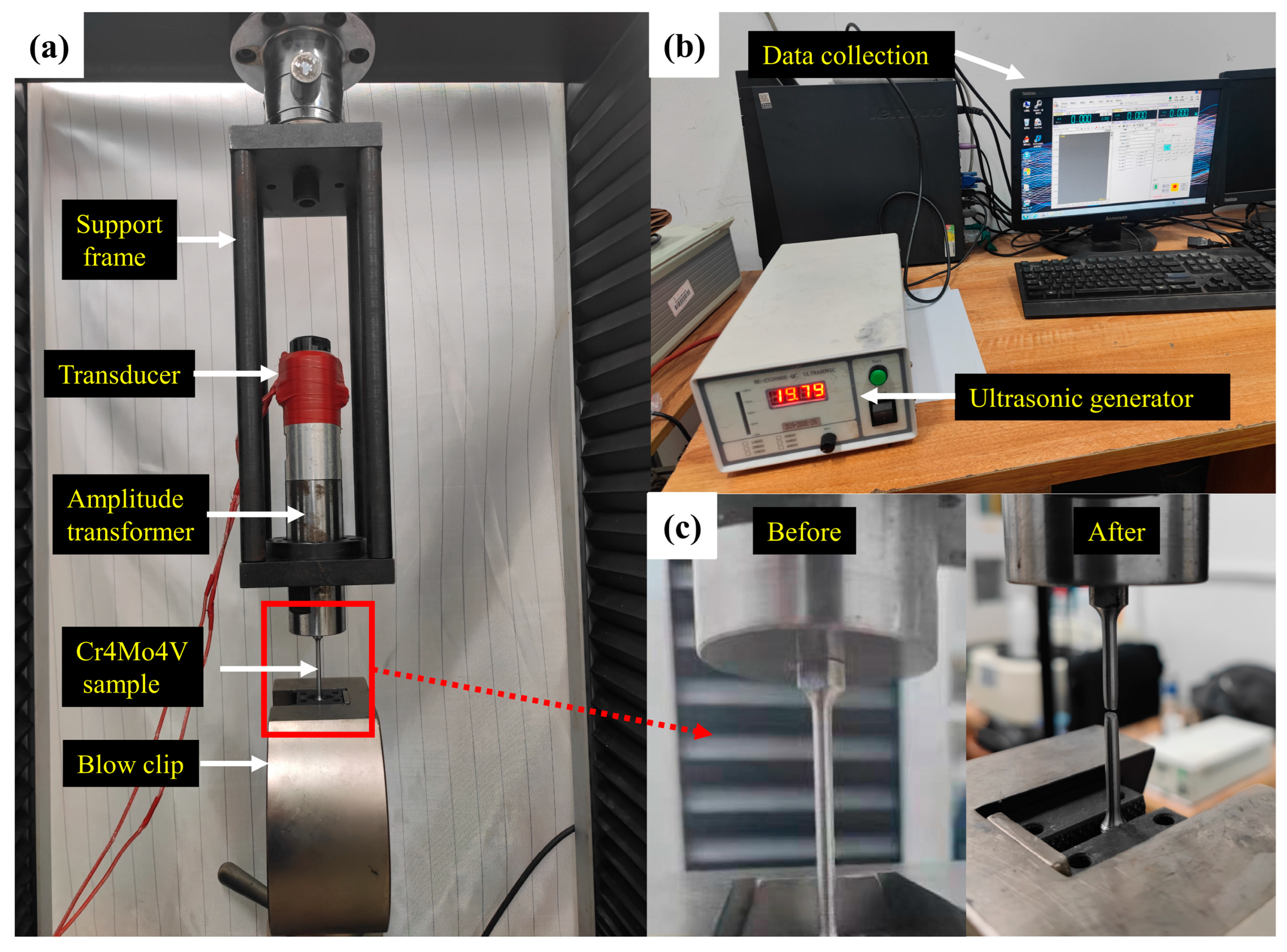
3.2. Experimental Devices

Figure 2a shows the support frame which is bolted to the upper fixed beam of the WDW-100kN (Jinan Hensgrand Instrument Co., Ltd., Jinan, China) type electronic universal testing machine. The transducer and ultrasonic horn are connected with double-headed bolts, and the ultrasonic horn is fixed to the support frame with a flange. The emissive transducer used in this paper was self-developed and the transducer dimensions were determined after modal analysis. The inverse piezoelectric effect of piezoelectric ceramics was utilized to convert electrical energy into mechanical vibration. One end of the specimen was connected to the ultrasonic horn by a thread, and the other end was clamped to the moving beam of the tensile machine by the WDW-100 kN type electronic universal testing machine. Figure 2b shows the ultrasonic generator and data collection device. The ultrasonic vibration system mainly consists of a CS-2000E-QC (Nova Instruments, Fremont, CA, USA) series ultrasonic generator, transducer, and ultrasonic horn. Figure 2c shows the morphology of Cr4Mo4V before and after a tensile fracture.

3.3. Experimental Program

The vibration frequency was obtained using the automatic scanning function of the ultrasonic generator, shown directly on the display. The no-load frequency of ultrasonic vibration was 19,780 Hz, which dropped to 19,730 Hz after loading, and the vibration direction was the same as the stretching direction. The amplitude was adjusted by varying the power percentage of the ultrasonic generator, and the values of vibration amplitude at different powers were obtained using an OPTOMET digital laser vibrometer. The measurement of the vibration amplitude was completed before the ultrasonic vibration system was assembled in the universal testing machine. The laser vibrometer emitted a laser beam to the top surface of the ultrasonic horn, received the reflected signal, and then transferred the received data to the computer. By using the software OptoSCAN (https://www.optomet.com/products/software/optoscan, accessed on 7 October 2023) that matches the laser vibrometer, the curve of the displacement with the change of the top surface and the corresponding amplitude were obtained.
The amplitude used in the calculations in this paper is the nominal amplitude under no-load conditions, which may change due to the shape and position of the ultrasonic horn or during the experimental process. All experiments were performed at room temperature, and the sound energy density at different ultrasonic amplitudes was obtained according to Equation (13), as shown in Table 2. The strain rate was changed by changing the tensile rate of the universal testing machine, and the correspondence between ultrasonic duration and strain rate is shown in Table 3.
To investigate the effect of different aplitudes and strain rates on the flow stress-strain curve, the following steps were performed. First, the room temperature stretches with strain rates of 0.00125/s, 0.005/s, and 0.02/s were performed without ultrasonic vibration conditions. The stress-strain curves for three different strain rates were obtained as the original comparison curves. Then, single-factor tests with amplitude and strain rate were conducted to obtain stress-strain curves for different states under ultrasonic conditions. Each single-factor test group was repeated at least three times to ensure the consistency of the test data.

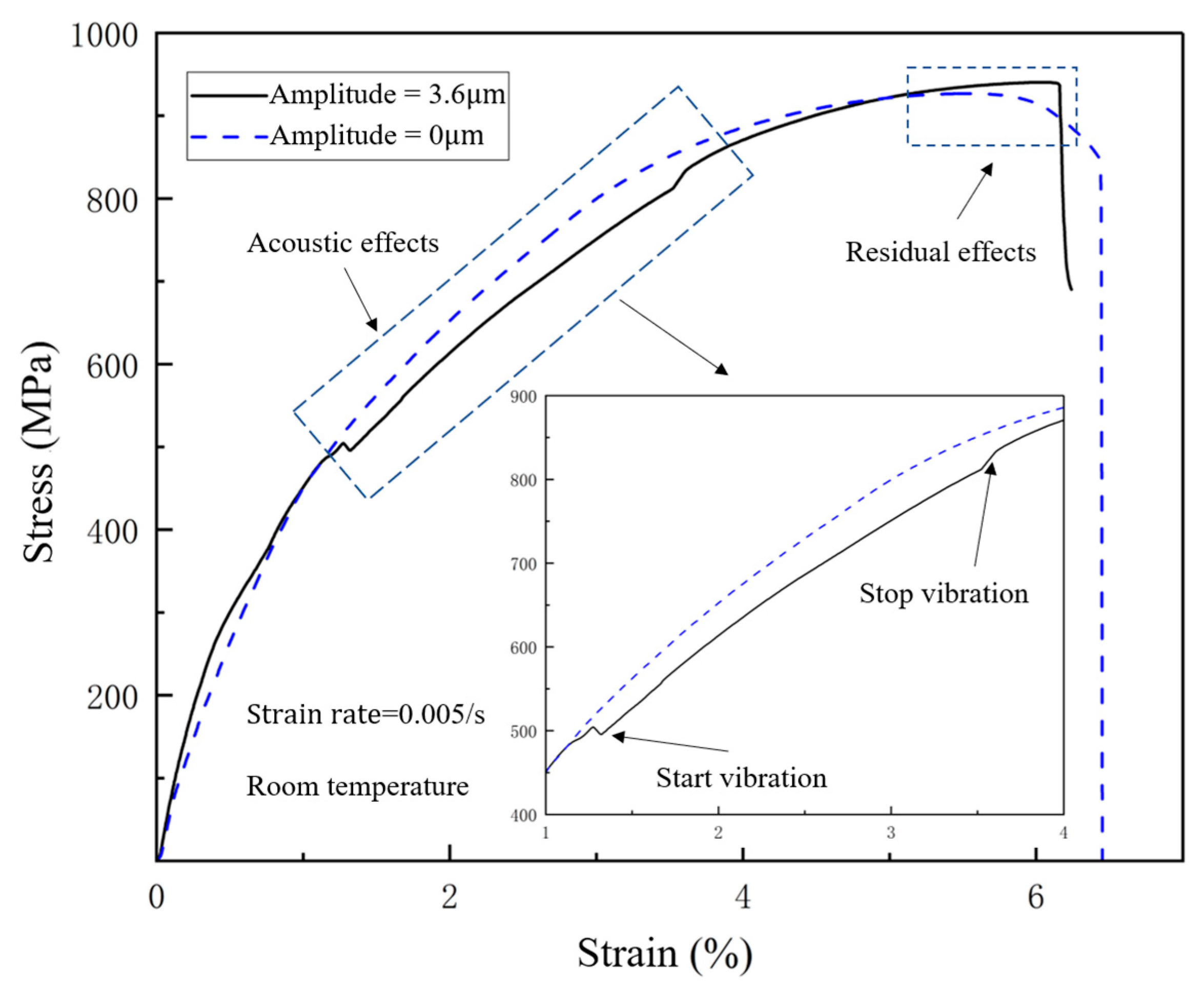
3.4. Discussion of Experimental Results

The UVAT tests were conducted by varying the amplitude and strain rate in the single-factor tests. The stress-strain curves obtained by fitting the data from each group of tests showed that ultrasonic vibration effectively reduces the flow stress; the result is shown in Figure 3. Under the strain rate of 0.005/s, a specific experimental result was selected from the repeated experiments with no ultrasonic vibration and with a vibration amplitude of 3.6 μ m . In order to observe the acoustic effect on the stress-strain curve, ultrasonic vibrations were started at the 6th second of stretching and continued for 10 s. After the ultrasound was loaded, the flow stress immediately decreased. The strain in the horizontal coordinate was the dimensionless deformation with an original gauge length of 40 mm. The stress drop was between 1% and 2% (0.005 1/s × 6 s × (40 mm/100 mm) × 100% = 1.2%), as shown in Figure 3. After ultrasonic unloading, the flow stress gradually increased, possibly because the lattice defects of the material immediately absorbed the energy of high-frequency vibrations, and led to periodic oscillations of the strain field. The combined effect showed a reduction in flow stress at the macroscopic level. As the ultrasonic vibration stopped, the material vibration gradually decayed under the effect of damping. The energy absorbed by the defect dissipated, and its softening effect also disappeared. As the strain increased, the flow stress with ultrasonic vibration increased and was higher than that without ultrasonic vibration. It is assumed that the change in dislocation density also accumulated during the ultrasonic vibration. During the ultrasound duration, acoustic hardening from dislocation proliferation coexisted with acoustic softening. Overall acoustic softening was higher than the equilibrium value of change, which resulted in lower flow stress. After the dissipation of ultrasonic unloading energy, residual hardening occurred. Figure 3 also shows that the elongation of the material decreased and the tensile strength increased under ultrasonic conditions.
Due to the additions of ultrasound, the loading changed periodically. To keep the consistency of the experiment, each set of tests was repeated at least three times. The results of the three repetitions are shown in Figure 4, where the larger the amplitude, the greater the scattering. Figure 5a shows the stress-strain curves for different amplitudes at a strain rate of 0.005/s. The acoustic softening effect of the material mainly occurred in the plastic phase. The softening of the material was not obvious when the amplitude was low, and the softening effect increased as the amplitude increased. The 2.7 μ m data to the left of the no ultrasonic vibration data were predominantly for the elastic deformation phase. This could be the result of experimental error. It is also possible that the ultrasonic energy accelerated the atoms during the elastic phase, reducing the atomic spacing and increasing the elastic modulus. Figure 5b shows the relationship between the drop value of flow stress and the true strain for different amplitudes. These data are based on experimental results of average stress-strain curves. The real stress change values at different real strains are obtained using data processing software MATLAB R2022a. The degree of flow stress drop increased slowly with strain at an amplitude of 2.7 μ m . The flow stress drop varied steadily around 40 MPa at an amplitude of 3.2 μ m , and the flow stress drop increased and then decreased with true strain at an amplitude of 3.6 μ m . The data in all three cases were generated during the duration of the ultrasound. This could be due to the complex evolution of dislocation density in the ultrasonic energy field, where dislocation proliferation and annihilation “compete” with each other. When the amplitude reaches a certain value, the proliferation and annihilation of dislocations may reach an equilibrium. At higher amplitudes, as strain increases, dislocations gradually accumulate, the required critical shear stress increases, and the degree of decrease in flow stress decreases.
Figure 6a shows that the flow stress at a high strain rate of 0.02/s is higher than the other two curves at an amplitude of 3.2 μ m for ultrasonic vibration conditions, and the two curves at strain rates of 0.00125/s and 0.005/s are similar. In this regard, the stress-strain curves of ultrasonic vibration stretching show the same trend as normal stretching. This is mainly because the work hardening at high strain rates is more severe than that at low strain rates. Meanwhile, the stretching time becomes shorter at higher strain rates, and the vibration time becomes shorter. The vibration time was set to a strain rate of 0.02/s for 2 s and 10 s for the other two curves. Figure 6b shows the partial stress-strain curves with and without the application of ultrasonic vibration at different strain rates. It also shows that the duration of ultrasonic vibration also has a strong influence on the dislocation density evolution, which is consistent with the results of Ref. [12]. Under ultrasonic conditions, the acoustic softening effect diminished with increasing strain rate, which was not significant at smaller strain rate changes but was significant at larger strain rate changes, which is similar to the conclusion of another study [37].

4. Model Development and Discussion

4.1. Flow Stress Constitutive Parameters for the Cr4Mo4V Bearing Steel

The identification of the constitutive parameters was obtained by fitting the experimental data. Under ultrasonic conditions, the vibration excitation was continuously and variably loaded onto the workpiece, which is prone to random discrete errors. Therefore, to ensure the reliability of the results, the method of repeated tests was utilized. Single-factor fitting, which fixes the other independent variables and changes only one independent variable, is the most common fitting method. However, the parameters determined through single-factor fitting alone are susceptible to random dispersion errors, and the parameter values calculated first and brought into the solution of subsequent parameters will amplify the errors; therefore, the results are often not optimal globally. Genetic algorithms are a parallel stochastic optimization method that mimics nature’s theory of heredity and biological evolution [38]. It is capable of accomplishing multi-parameter identification under multi-factor conditions. In this paper, the number of parameters was first reduced by a single-factor fitting method, and then, the final material parameters were determined using a genetic algorithm.
The objective function for the parameter optimization was defined as the sum of the square of the difference between the flow stress prediction and experimental data at each sample point, which is expressed as follows:
min f x , f x = j = 1 N i = 1 M σ i , j σ i , j * 2
where f x is the overall error function, N is the number of test groups involved in the fit, M is the number of sampling points in a single group (the number of stress-strain data), σ i , j is the calculated value of the i th flow stress model for the j th group of tests, and σ i , j * is the experimental value of the flow stress under the same conditions. The genetic algorithm mainly performs screening by selection, crossover, and variation to obtain the optimal solution. The main operation process is shown in Figure 7.
When the temperature was high enough, the flow stress was independent of temperature. It can also be observed from our results of the high-temperature deformation behavior of M50 bearing steel that the flow stress changes less when the temperature fluctuates more [36]. The material properties of M50 and Cr4Mo4V bearing steel are similar. In this paper, the stress-strain curve of M50 bearing steel near the melting point of 1150 °C (1423 K) was used for a one-factor (true strain) fit to determine four parameters, as shown in Table 4. The fitting results are shown in Figure 8, and the goodness of fit was evaluated using the mean absolute error (MAE) and the coefficient of determination R 2 .
Genetic optimization algorithms have been used in many applications for the identification of constitutive parameters. It is a general method for parameter optimization. Studies have started to use genetic algorithms in combination with neural networks to obtain the optimized parameters [39]. In this study, a genetic optimization algorithm was used to fit stress-strain curves without vibration to obtain parameters independent of acoustic energy for the first time. The initial values of these parameters, independent of the ultrasonic vibrations, were used to determine the interval of their values under ultrasonic conditions.
Under ultrasonic vibration conditions, the acoustic energy reduced the thermally activated free energy on the one hand and changed the evolution of the dislocation density on the other hand. When the ultrasound was unloaded, the acoustic energy rapidly dissipated. The thermally activated free energy was no longer affected by the acoustic energy and the dislocation was permanently changed. Figure 3 shows that the flow stress suddenly increased and exceeded the flow stress of ordinary tension after ultrasonic unloading, and it can be assumed that residual acoustic hardening of the material occurred. It is generally believed that the initial dislocation density of the specimen determines whether residual hardening or softening is an important factor, and metal materials with lower dislocation density tend to undergo residual hardening under stronger acoustic fields. The tests in this paper used annealed bearing steel with lower dislocation density and defects, which reduced the hardness [40]. This view is consistent with the test results.
According to Equation (10), η k 1 and η k 2 are related to the amplitude of the ultrasonic vibration and reflect the acoustic residual effect. This paper did not consider η k 2 , and the numerical solution of η k 1 at different amplitudes was obtained using the nonlinear fitting. Polynomial fitting was then used to obtain the relationship between η k 1 and amplitude A as:
η k 1 = 0.9293 A 0.4307 A 2 + 0.0742 A 3
The specific procedure can be found in Appendix A.
The final values of each parameter under ultrasonic conditions were determined using a genetic optimization algorithm (2086 sample points for the six sets of test conditions) as shown in Table 5.

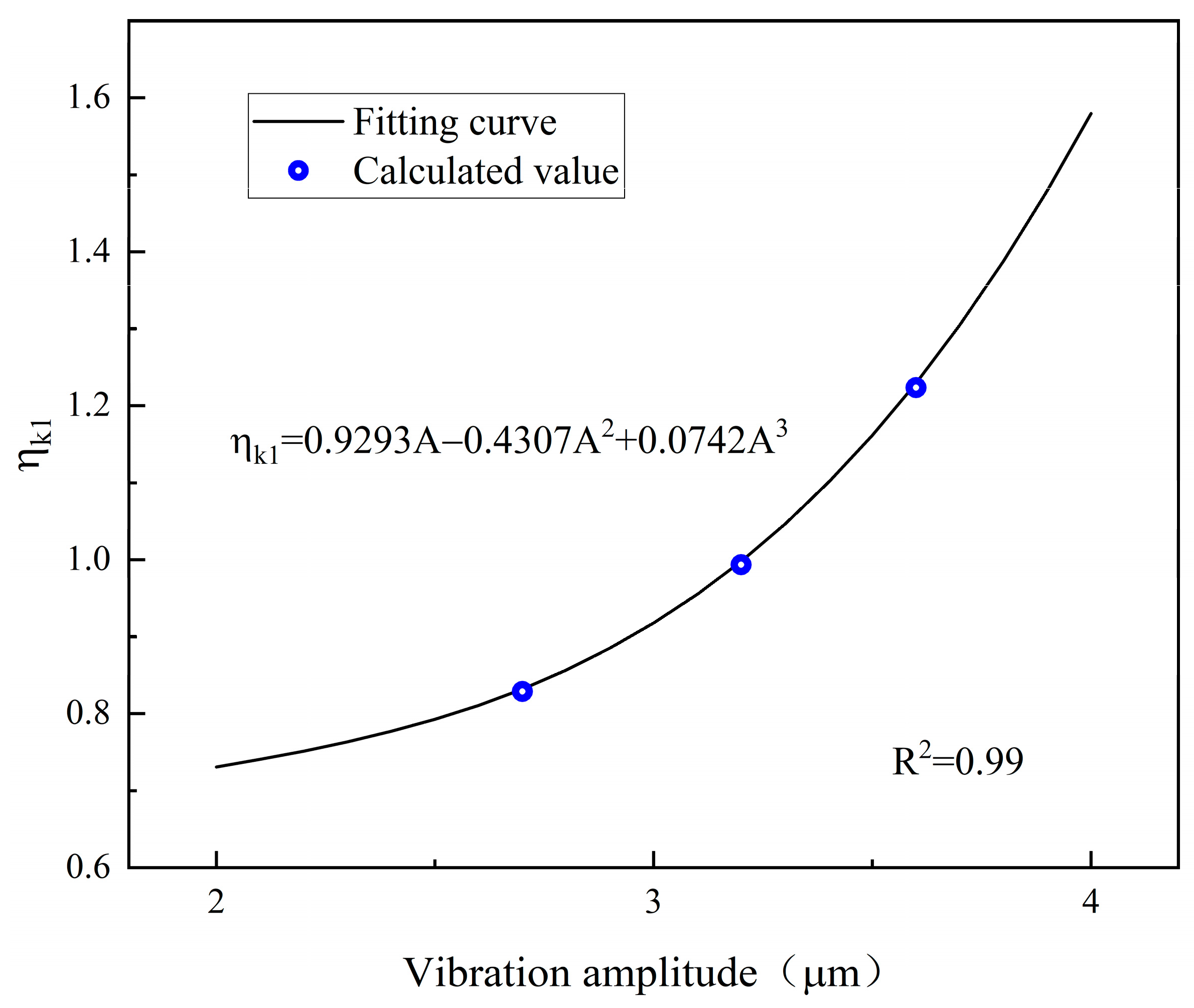
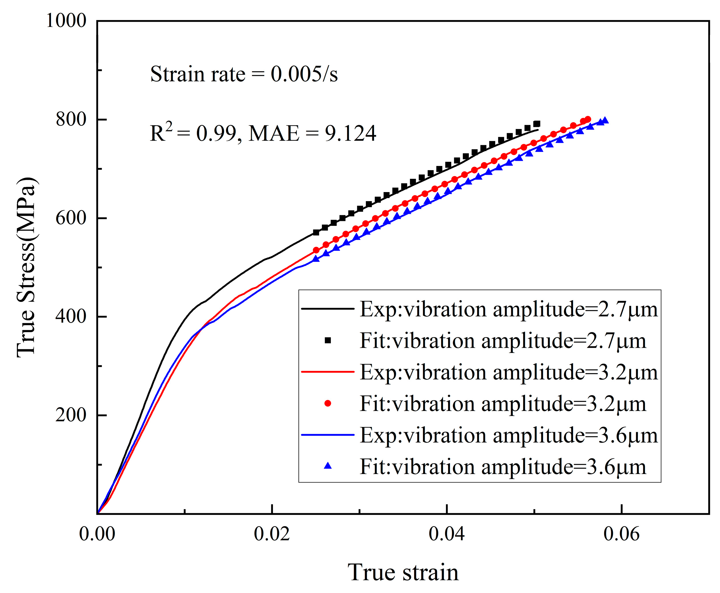
4.2. Model Fitting and Discussion

In this paper, parameter identification was first carried out using stress-strain data under six experimental conditions. Our model fit the data well for these six conditions. We expected the model to have a better prediction of the data for the experimental conditions that were not included in the fitting. Therefore, the stress-strain data for the other three experimental conditions were predicted and compared to the experimental values. Six experimental conditions were analogous to training samples and three experimental conditions were analogous to test samples.
The stress-strain relationships obtained by fitting experimental data without ultrasonic vibration are shown in Figure 9. The parameters related to the acoustic energy (amplitude A = 0 μ m ) were included and can be well-suited. The MAE was 29.36.
The stress-strain relationships obtained by fitting experimental data at different amplitudes of ultrasonic vibration are shown in Figure 10. The MAE was 9.124.
The flow stress model established by the theory of dislocation dynamics and thermal activation shows that ultrasonic vibration is effective in lowering the energy barrier of dislocation motion, causing the dislocation density to proliferate and annihilate. The constant m in Equation (14) was identified as 1, indicating that the stress reduction resulting from acoustic softening is proportional to the acoustic energy density E , which is the square of the vibration amplitude A . The relationship between the square of the amplitude and the average reduction in flow stress is consistent with the experimental results within the present experimental range, as shown in Figure 11.
In this paper, our model showed that the change in flow stress was mainly caused by the acoustic energy affecting the dislocation density evolution and the reduction of the thermal activation threshold compared to the absence of ultrasonic vibration. The athermal stress threshold and the thermal stress threshold at each strain were calculated according to Equations (12) and (16). Then, the values of the variation of these two components on the flow stress were obtained according to Equations (14) and (20), with the results shown in Figure 12. The hardening due to the dislocation value added by the acoustic energy increased with increasing amplitude, and the acoustic softening also increased with increasing amplitude. The calculated values of the flow stress reduction caused by the combination of the two were consistent with the experimental result.

4.3. Model Validation and Error Analysis

The constructed flow model needs to predict the stress-strain relationship of the material under different conditions. Therefore, the ultrasound-assisted tensile stress-strain curves of Cr4Mo4V bearing steel under three different conditions were predicted by the model in this paper. The corresponding parameter values for the three conditions are shown in Table 6. The results of the experimentally obtained flow stresses at each strain with the model predictions are shown in Figure 13. The data shown in Figure 13 were not obtained by fitting; they were calculated from the model parameters determined earlier. These sample data compared poorly with the fitted sample data.
The results show good consistency between our predictions and the experimental results. Figure 13 shows the MAE and the AARE of the flow stress prediction for the three cases. The maximum AARE was 5.64% for the third prediction condition under the parameter conditions of this experiment:
A A R E = 1 n i = 1 n E i P i E i × 100 %
where E i and P i are the experimental data and predicted value, respectively.
The second case is the best prediction, which shows a greater acoustic softening and dislocation proliferation effect with increasing amplitude compared to Figure 5a. The dislocation growth rate gradually increases, making the combined softening effect seem to decrease at high amplitudes instead. However, the dislocation density cannot increase indefinitely and will eventually reach a saturation value. Therefore, polynomials in terms of amplitude may not be applicable in the case of larger amplitudes, as noted in Appendix A, and a larger experimental range is needed to determine the relationship between dislocation density proliferation and amplitude.

5. Conclusions

(1)
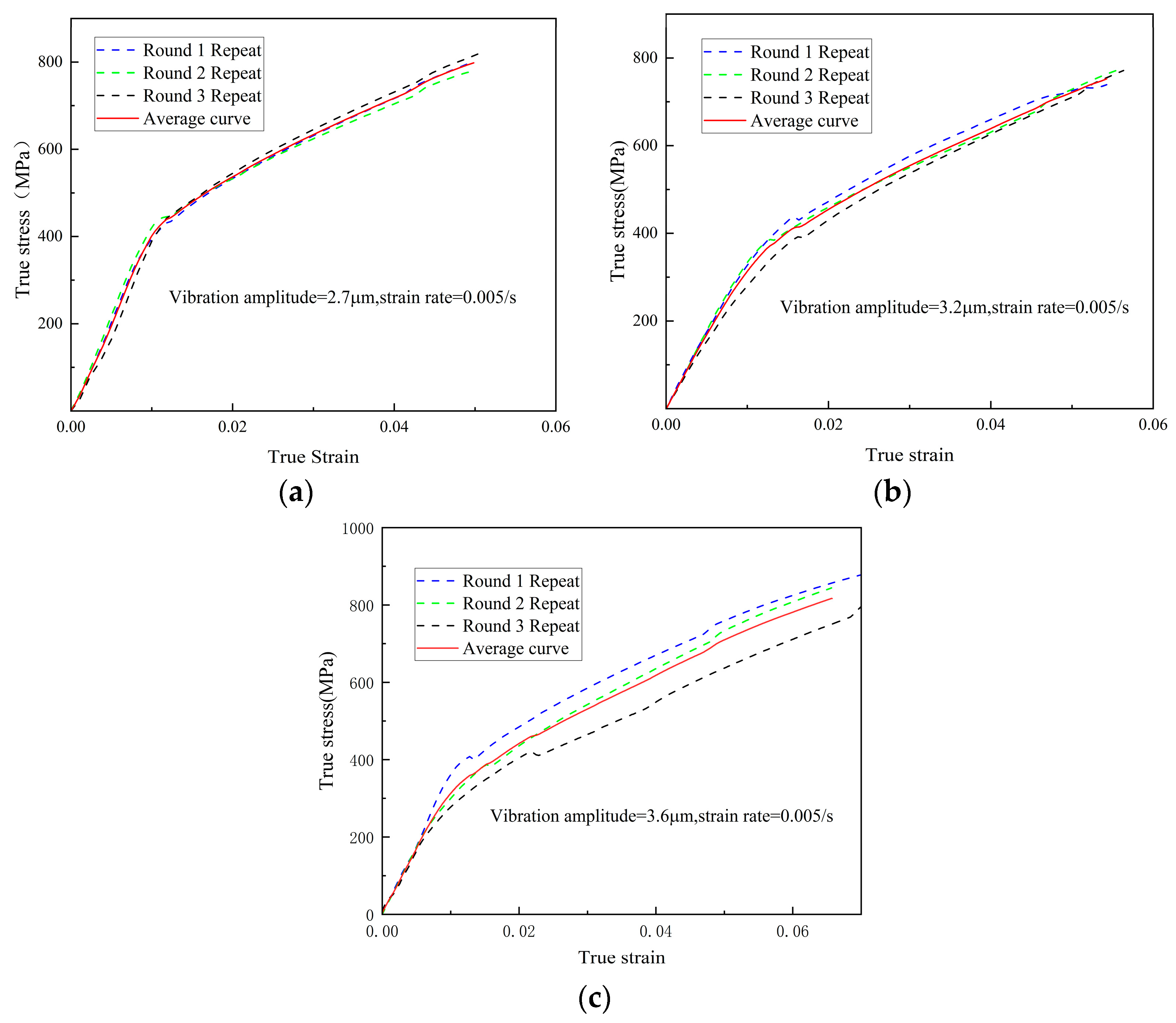
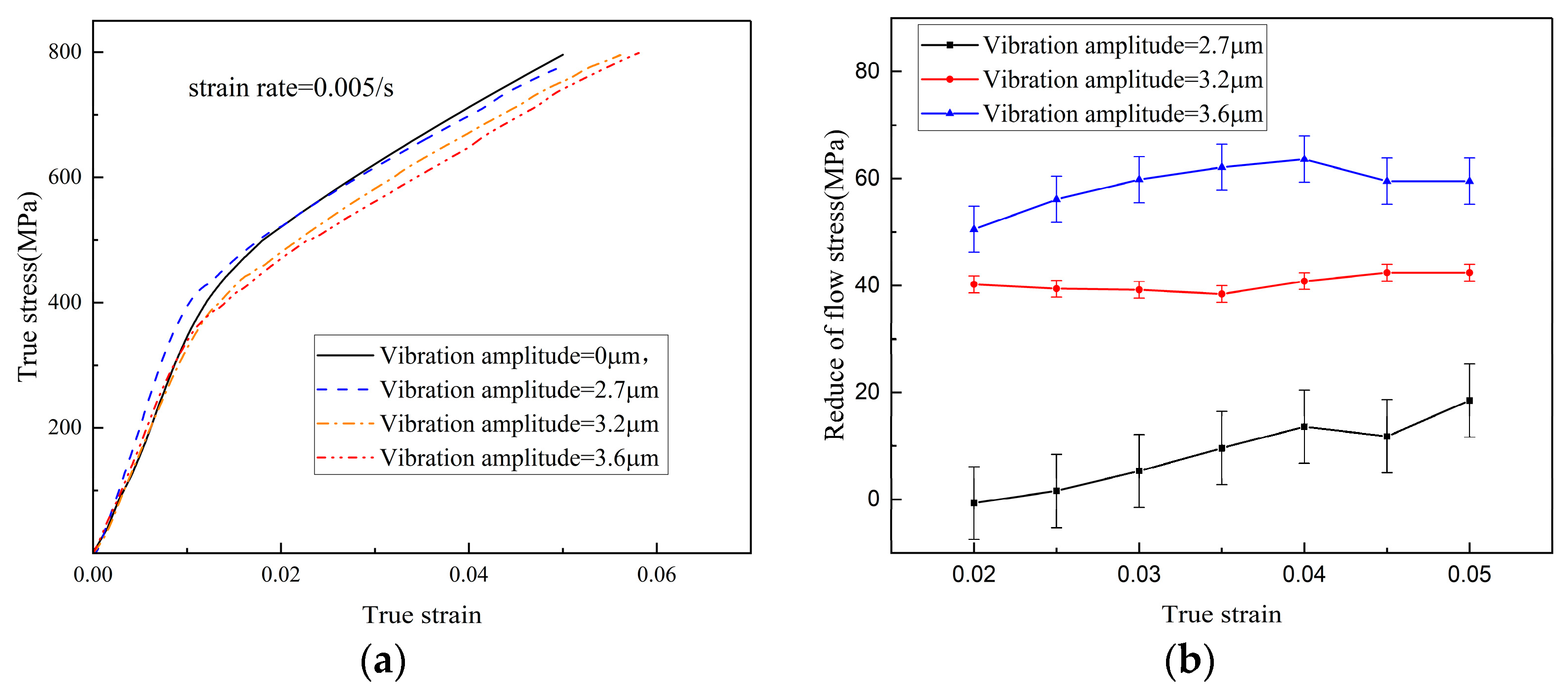
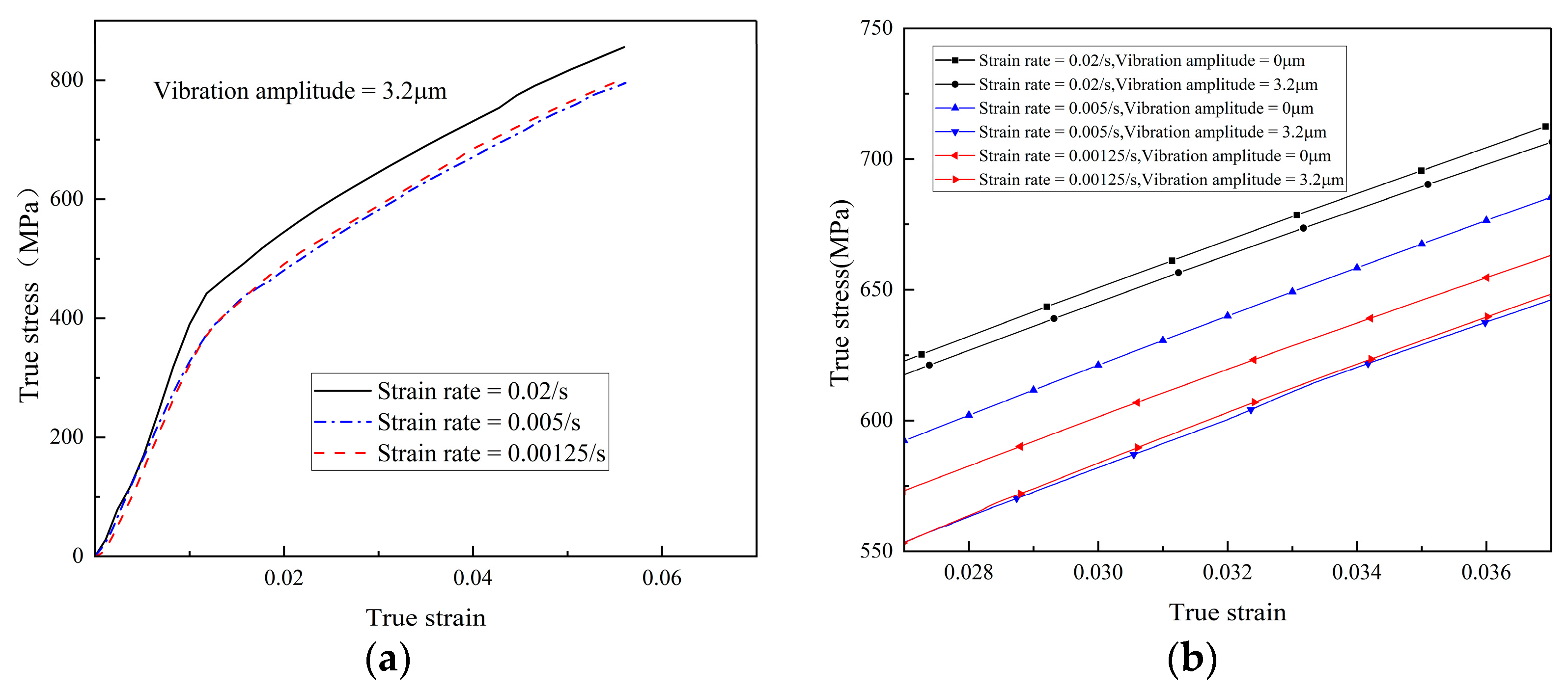
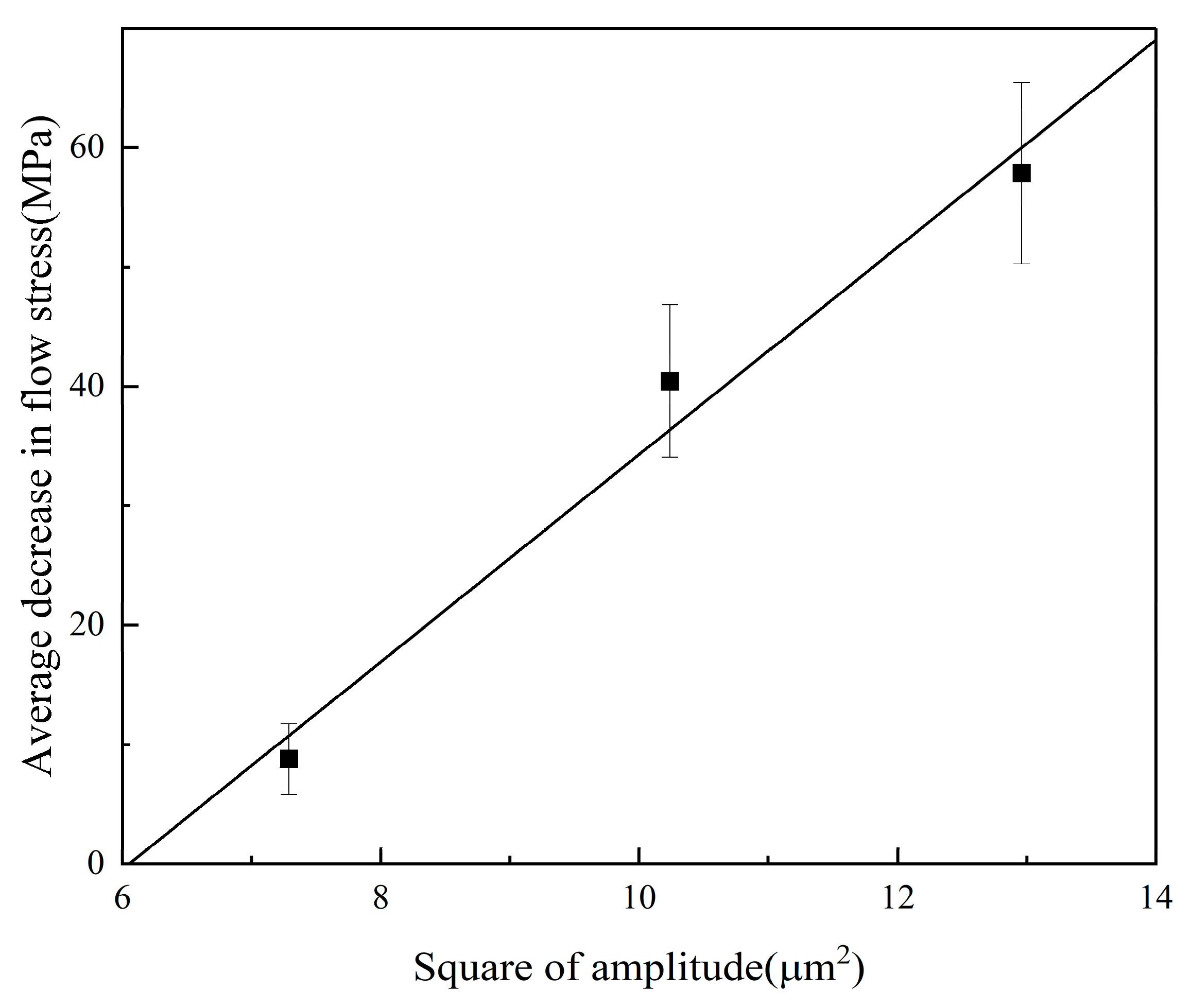
This investigation demonstrates that the yield strength of the material decreases in ultrasonic vibration-assisted stretching of Cr4Mo4V bearing steel, and the reduction of flow stress increases with increasing amplitude; the strain rate shows a nonlinear relationship with the acoustic softening effect under ultrasonic conditions.
(2)
The material dislocation density is proliferated and annihilated due to the influence of acoustic energy. At the end of the vibration, the flow stress recovered and exceeded that of the flow stress without ultrasonic conditions.
(3)
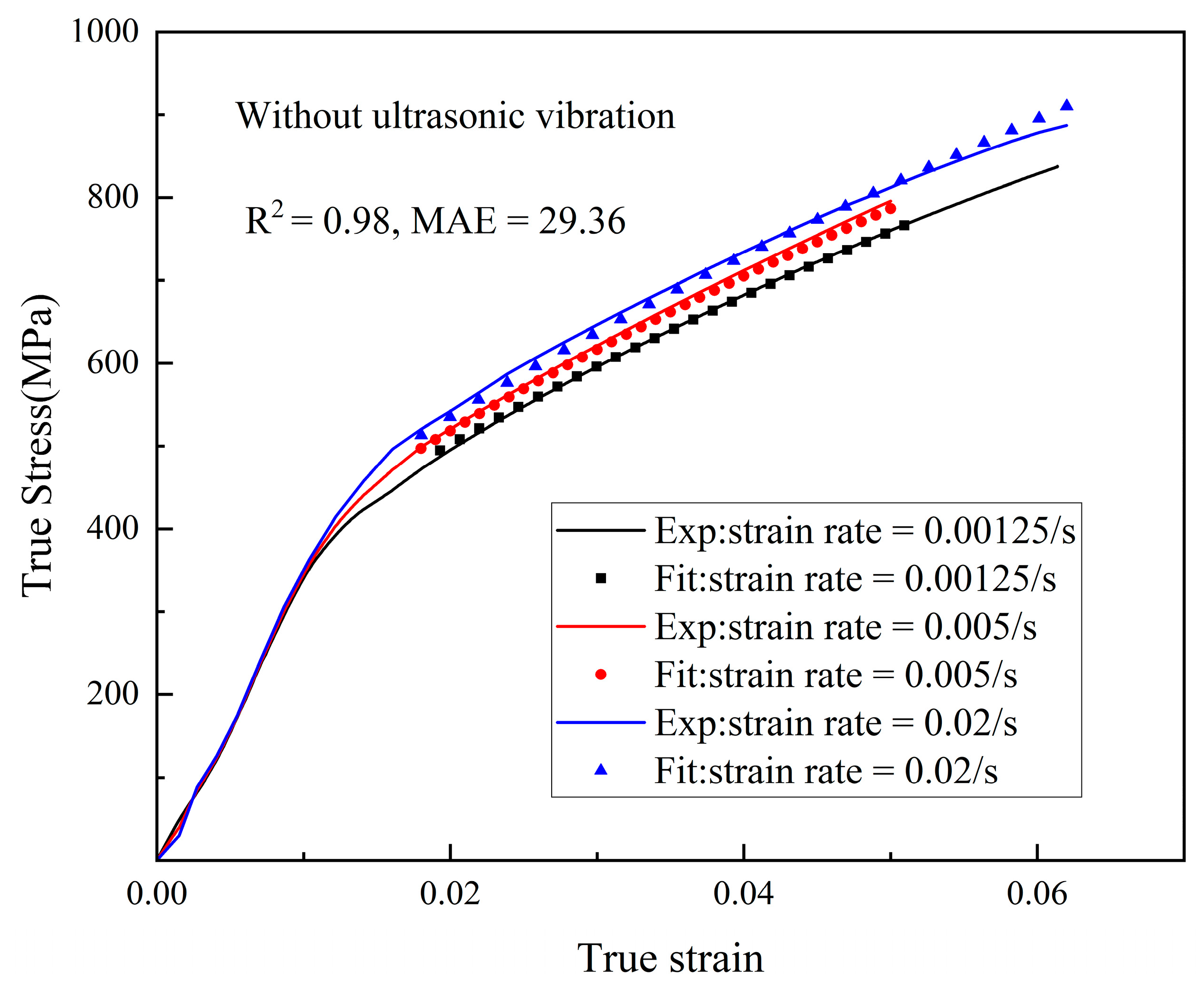
Based on the thermal activation mechanism and dislocation evolution theory, the flow stress model of Cr4Mo4V under ultrasonic vibration conditions was constructed by taking into account the crystal structure. The optimal values of each parameter were obtained based on a genetic algorithm, and the results showed that the model is effective at predicting the stress-strain relationship under different amplitudes and strain rates. The MAE values under the three ultrasonic vibration conditions predicted in this experiment were 29.70, 8.182, and 38.36, and the AARE values were 4.49%, 1.27%, and 5.64%. However, there is a saturation value for dislocation proliferation, and the polynomial expression η k 1 as an amplitude may not be applicable at larger amplitudes. In future studies, η k 1 can be determined as a function of amplitude by using a larger amplitude parameter. The validity of the model can be further verified by measuring the real dislocation density to compare with the existing findings. To validate our model, more tests about fracture imaging, TEM, EBSD, etc., should be conducted.
(4)
High-frequency ultrasonic vibration was shown to make Cr4Mo4V bearing steel more prone to plastic deformation and increase surface hardening after processing. The ultrasonic-assisted process is effective at reducing the machining difficulty, improving the surface quality, and increasing the use of bearing steel performance. This study provides a theoretical basis for the ultrasonic-assisted process of bearing steel.

Author Contributions

Conceptualization, S.Y.L. and M.Z.; methodology, M.Z. and L.Z.; software Z.L.; validation, Z.L., M.Z. and J.M.; formal analysis, G.L., Y.F. and J.M.; investigation, M.Z., G.L. and L.Z.; resources, S.Y.L., J.M., Y.F. and G.L.; data curation, Z.L. and M.Z.; writing—original draft preparation, Z.L.; writing—review and editing, Z.L. and M.Z.; visualization, Z.L. and M.Z.; supervision, M.Z., J.M. and L.Z.; project administration, G.L. and J.M.; funding acquisition, J.M. and Y.F. All authors have read and agreed to the published version of the manuscript.

Funding

This work was supported by the National Natural Science Foundation of China Youth Program [52205485], Shanghai Pujiang Program [20PJ1404700] and the Young Scientific Research Team Cultivation Program of SUES [QNTD202112].

Data Availability Statement

The raw data supporting the conclusions of this article will be made available by the authors on request.

Conflicts of Interest

The authors declare that they have no known competing financial interests or personal relationships that could have appeared to influence the work reported in this paper.

Appendix A

The flow stress under different ultrasonic vibration conditions can be expressed as follows:
When the amplitude is 2.7   μ m :
σ u = M 2 α μ b k 2 k 1 1 + η k 1 1 C exp k 2 2 ε + σ 0 + σ t h u 1
When the amplitude is 3.2   μ m :
σ u = M 2 α μ b k 2 k 1 1 + η k 1 2 C exp k 2 2 ε + σ 0 + σ t h u 2
When the amplitude is 3.6   μ m :
σ u = M 2 α μ b k 2 k 1 1 + η k 1 3 C exp k 2 2 ε + σ 0 + σ t h u 3
According to the genetic algorithm in the text, η k 1 ( 1 ) , η k 1 ( 2 ) , and η k 1 ( 3 ) can be obtained.
The relationship between η k 1 and the amplitude A is obtained by polynomial fitting.
Figure A1. The fitted effect diagram.
Metals 14 00143 g0a1

References

  1. Wei, Y.H.; Yu, X.F.; Su, Y.-F.; Shen, X.Y.; Xia, Y.Z.; Yang, W.W. Effect of residual stress and microstructure evolution on size stability of M50 bearing steel. J. Mater. Res. Technol. 2021, 10, 651–661. [Google Scholar] [CrossRef]
  2. ISO 281; Rolling Bearings Dynamic Load Ratings and Rating Life. ISO: Geneva, Switzerland, 2017.
  3. Yang, L.; Xue, W.; Gao, S.; Li, L.; Cao, Y.; Liu, H.; Duan, D.; Li, D.; Li, S. Rolling contact fatigue behaviour of M50 bearing steel with rare earth addition. Int. J. Fatigue 2023, 177, 107940. [Google Scholar] [CrossRef]
  4. Wang, F.; Qian, D.; Hua, L.; Lu, X. The effect of prior cold rolling on the carbide dissolution, precipitation and dry wear behaviors of M50 bearing steel. Tribol. Int. 2019, 132, 253–264. [Google Scholar] [CrossRef]
  5. Jiang, H.; Song, Y.; Wu, Y.; Shan, D.; Zong, Y. Microstructure evolution and mechanical anisotropy of M50 steel ball bearing rings during multi-stage hot forging. Chin. J. Aeronaut. 2021, 34, 254–266. [Google Scholar] [CrossRef]
  6. Zhou, L.; Tang, G.; Ma, X.; Wang, L.; Zhang, X. Relationship between microstructure and mechanical properties of M50 ultra-high strength steel via quenching-partitioning-tempering process. Mater. Charact. 2018, 146, 258–266. [Google Scholar] [CrossRef]
  7. Kim, D.M.; Kim, H.I.; Park, H.W. Tool wear, economic costs, and CO2 emissions analysis in cryogenic assisted hard-turning process of AISI 52100 steel. Sustain. Mater. Technol. 2021, 30, e00349. [Google Scholar] [CrossRef]
  8. Shao, G.; Li, H.; Zhan, M. A Review on Ultrasonic-Assisted Forming: Mechanism, Model, and Process. Chin. J. Mech. Eng. 2021, 34, 99. [Google Scholar] [CrossRef]
  9. Sonia, P.; Jain, J.K.; Saxena, K.K. Influence of ultrasonic vibration assistance in manufacturing processes: A Review. Mater. Manuf. Process. 2021, 36, 1451–1475. [Google Scholar] [CrossRef]
  10. Chen, K.; Zhang, Y.; Wang, H. Effect of acoustic softening on the thermal-mechanical process of ultrasonic welding. Ultrasonics 2017, 75, 9–21. [Google Scholar] [CrossRef]
  11. Cao, M.Y.; Hu, H.; Jia, X.D.; Tian, S.J.; Zhao, C.C.; Han, X.B. Mechanism of ultrasonic vibration assisted upsetting of 6061 aluminum alloy. J. Manuf. Process. 2020, 59, 690–697. [Google Scholar] [CrossRef]
  12. Yao, Z.; Kim, G.-Y.; Wang, Z.; Faidley, L.; Zou, Q.; Mei, D.; Chen, Z. Acoustic softening and residual hardening in aluminum: Modeling and experiments. Int. J. Plast. 2012, 39, 75–87. [Google Scholar] [CrossRef]
  13. Hu, J.; Shimizu, T.; Yoshino, T.; Shiratori, T.; Yang, M. Evolution of acoustic softening effect on ultrasonic-assisted micro/meso-compression behavior and microstructure. Ultrasonics 2020, 107, 106107. [Google Scholar] [CrossRef] [PubMed]
  14. Blaha, F.; Langenecker, B. Elongation of zinc monocrystals under ultrasonic action. Die Naturwissenschaften 1955, 42, 556. [Google Scholar] [CrossRef]
  15. Wang, X.; Wang, C.; Liu, Y.; Liu, C.; Wang, Z.; Guo, B.; Shan, D. An energy based modeling for the acoustic softening effect on the Hall-Petch behavior of pure titanium in ultrasonic vibration assisted micro-tension. Int. J. Plast. 2021, 136, 102879. [Google Scholar] [CrossRef]
  16. Kang, J.; Liu, X.; Xu, M. Plastic deformation of pure copper in ultrasonic assisted micro-tensile test. Mater. Sci. Eng. A 2020, 785, 139364. [Google Scholar] [CrossRef]
  17. Huang, H.; Pequegnat, A.; Chang, B.; Mayer, M.; Du, D.; Zhou, Y.N. Influence of superimposed ultrasound on deformability of Cu. J. Appl. Phys. 2009, 106, 113514. [Google Scholar] [CrossRef]
  18. Ting-jian, Z.; Li-xia, Z.; Juan, L. Mechanical behavior and constitutive modeling of magnesium alloy sheet in ultrasonic vibration assisted tensile test. J. Plast. Eng. 2020, 27, 170–176. [Google Scholar] [CrossRef]
  19. Gao, G.; Fu, Z.; Wang, Y.; Pan, X.; Xiang, D.; Zhao, B. Ultrasonic constitutive model and its application in ultrasonic vibration-assisted milling Ti3Al intermetallics. Chin. J. Aeronaut. 2023, 36, 226–243. [Google Scholar] [CrossRef]
  20. Shackelford, J.F.; Han, Y.-H.; Kim, S.; Kwon, S.-H. CRC Materials Science and Engineering Handbook; CRC Press: Boca Raton, FL, USA, 2016. [Google Scholar]
  21. Dutta, R.K.; Petrov, R.H.; Delhez, R.; Hermans, M.J.M.; Richardson, I.M.; Böttger, A.J. The effect of tensile deformation by in situ ultrasonic treatment on the microstructure of low-carbon steel. Acta Mater. 2013, 61, 1592–1602. [Google Scholar] [CrossRef]
  22. Siu, K.W.; Ngan, A.H.W.; Jones, I.P. New insight on acoustoplasticity—Ultrasonic irradiation enhances subgrain formation during deformation. Int. J. Plast. 2011, 27, 788–800. [Google Scholar] [CrossRef]
  23. Xie, Z.; Guan, Y.; Lin, J.; Zhai, J.; Zhu, L. Constitutive model of 6063 aluminum alloy under the ultrasonic vibration upsetting based on Johnson-Cook model. Ultrasonics 2019, 96, 1–9. [Google Scholar] [CrossRef]
  24. Kang, J.; Liu, X.; Niezgoda, S.R. Crystal plasticity modeling of ultrasonic softening effect considering anisotropy in the softening of slip systems. Int. J. Plast. 2022, 156, 103343. [Google Scholar] [CrossRef]
  25. Fu, Z.; Gao, G.; Wang, Y.; Wang, D.; Xiang, D.; Zhao, B. Investigation of acoustic softening and microstructure evolution characteristics of Ti3Al intermetallics undergoing ultrasonic vibration-assisted tension. Mater. Des. 2022, 222, 111015. [Google Scholar] [CrossRef]
  26. Fartashvand, V.; Abdullah, A.; Sadough Vanini, S.A. Investigation of Ti-6Al-4V alloy acoustic softening. Ultrason. Sonochem. 2017, 38, 744–749. [Google Scholar] [CrossRef] [PubMed]
  27. Chu, Z.; He, Q. Experimental Research on the Performance of High-Temperature Bearing Steel Cr4Mo4 V. Recent Pat. Mech. Eng. 2021, 14, 195–205. [Google Scholar] [CrossRef]
  28. Zerilli, F.J. Dislocation mechanics-based constitutive equations. Metall. Mater. Trans. A 2004, 35, 2547–2555. [Google Scholar] [CrossRef]
  29. Gao, C.Y.; Zhang, L.C.; Yan, H.X. A new constitutive model for HCP metals. Mater. Sci. Eng. A 2011, 528, 4445–4452. [Google Scholar] [CrossRef]
  30. Zhao, M.; Ji, X.; Liang, S.Y. Influence of AA7075 crystallographic orientation on micro-grinding force. Proc. Inst. Mech. Eng. Part B J. Eng. Manuf. 2018, 233, 1831–1843. [Google Scholar] [CrossRef]
  31. Gao, C.Y.; Lu, W.R.; Zhang, L.C.; Yan, H.X. A constitutive description of the thermo-viscoplastic behavior of body-centered cubic metals. Mater. Des. 2012, 36, 671–678. [Google Scholar] [CrossRef]
  32. Abed, F.H. Constitutive modeling of the mechanical behavior of high strength ferritic steels for static and dynamic applications. Mech. Time-Depend. Mater. 2010, 14, 329–345. [Google Scholar] [CrossRef]
  33. Krausz, A.S.; Krausz, K. Unified constitutive laws of plastic deformation; Elsevier: Amsterdam, The Netherlands, 1996. [Google Scholar]
  34. Yao, Z.; Kim, G.-Y.; Faidley, L.; Zou, Q.; Mei, D.; Chen, Z. Acoustic Softening and Hardening of Aluminum in High-Frequency Vibration-Assisted Micro/Meso Forming. Mater. Manuf. Process. 2013, 28, 584–588. [Google Scholar] [CrossRef]
  35. Qian, C.; Li, K.; Rui, S.-S.; Hou, M.; Zhang, X.; Wu, Y.; Cai, Z. Magnetic induced re-dissolution and microstructure modifications on mechanical properties of Cr4Mo4V steel subjected to pulsed magnetic treatment. J. Alloys Compd. 2021, 881, 160471. [Google Scholar] [CrossRef]
  36. Chen, G.; Lu, X.; Yan, J.; Liu, H.; Baoguang, S. High-Temperature Deformation Behavior of M50 Steel. Metals 2022, 12, 541. [Google Scholar] [CrossRef]
  37. He, Y.; Zhang, J.; Zhou, W.; Tang, J.; Xu, Y.; Zhang, Y. Study on force reduction mechanism in ultrasonic-assisted grinding based on single-grain scratching. Arch. Civ. Mech. Eng. 2022, 22, 80. [Google Scholar] [CrossRef]
  38. Lin, C.-C.; Deng, D.-J. Dynamic Load Balancing in Cloud-Based Multimedia System Using Genetic Algorithm. In Advances in Intelligent Systems and Applications—Volume 1; Chang, R.-S., Jain, L.C., Peng, S.-L., Eds.; Springer: Berlin/Heidelberg, Germany, 2013; pp. 461–470. [Google Scholar]
  39. Jun, D.; Yuchuan, G.U.; Xia, H.; Kun, S.; Shiqing, L.U.; Lusheng, W. Research on Prediction Accuracy of Flow Stress of 304 Stainless Steel Based on Artificial Neural Network Optimized by Improved Genetic Algorithm. J. Mech. Eng. 2022, 58, 78–86. [Google Scholar] [CrossRef]
  40. Shen, Q.; Huang, D.; Li, F.; Liu, M.; Wang, X. Microstructures and mechanical properties of the precipitation strengthened Al0.4Cr0.7FexNi2V0.2 high entropy alloys. Mater. Sci. Eng. A 2023, 864, 144606. [Google Scholar] [CrossRef]
Figure 1. Geometry diagram of the Cr4Mo4V bearing steel specimen.
Metals 14 00143 g001
Figure 2. (a) UVAT experimental system, (b) data collection device, and (c) Cr4Mo4V before and after testing.
Metals 14 00143 g002
Figure 3. Comparison of stress-strain curves of Cr4Mo4V bearing steel with and without ultrasonic vibration.
Metals 14 00143 g003
Figure 4. Results of repeated experiments: (a) vibration amplitude = 2.7 μ m and strain rate = 0.005/s, (b) vibration amplitude = 2.7 μ m and strain rate = 0.005/s, and (c) vibration amplitude = 3.6 μ m and strain rate = 0.005/s.
Metals 14 00143 g004
Figure 5. (a) The flow stress-strain curves at different amplitudes and (b) the value of the decrease in flow stress with strain at different amplitudes.
Metals 14 00143 g005
Figure 6. (a) The flow stress-strain curves for different strain rates under ultrasonic vibration conditions and (b) the comparison of flow stress-strain curves with and without ultrasonic vibration at different strain rates.
Metals 14 00143 g006
Figure 7. Genetic algorithm operation flow chart.
Metals 14 00143 g007
Figure 8. The effect of fitting the athermal stress term. (Data from Ref. [36]).
Metals 14 00143 g008
Figure 9. Comparison of experimental results with fitting results for different strain rates without vibration.
Metals 14 00143 g009
Figure 10. Comparison of the experimental results with the fitting results at different amplitudes.
Metals 14 00143 g010
Figure 11. The relationship between the square of the amplitude and the average decrease of the flow stress.
Metals 14 00143 g011
Figure 12. Comparison of calculated and experimental results for acoustic effects of different amplitudes.
Metals 14 00143 g012
Figure 13. Comparison and error of predicted results with experimental results for different ultrasonic vibration conditions: (a) serial No. 1, (b) serial No. 2, and (c) serial No. 3.
Metals 14 00143 g013
Table 1. Chemical compositions (wt%).
CMnSiSPNiCrMoVCu
Cr4Mo4V0.750.350.40.020.030.203.84.00.90.2
M50 [36]0.820.240.21///4.204.221.10/
Table 2. The acoustic energy density of different amplitudes.
Serial No.Power (W)Frequency (Hz) Amplitude   ( μ m ) Acoustic   Energy   Density   ( J / m 3 )
10000
2120019,7302.7885.1
3160019,7303.21243.2
4240019,7303.61573.4
Table 3. Duration of vibration for different strain rates.
Strain rate (/s)0.001250.0050.02
Duration of vibration (s)10102
Table 4. Athermal stress model parameters.
Parameter k 1 k 2 C σ 0
Value0.062422.790.02247.5
Table 5. Parameter values used in the model and experiments.
ParametersSymbolValues
Parameters obtained from references [30,31]Taylor factor M 3.06
Coefficient in Equation (6) α 1/3
Burgers vector length (nm) b 0.286
Reference strain rate ε 0 1 × 10 3
Saturated reference strain rate ε s 0 1 × 10 8
Working parametersKelvin temperature (K) T 293
Loading frequency (Hz) f 19,730
Parameters identified from experimentsCoefficient in Equation (18) Y ^ 8319
Coefficient in Equation (18) n 1 0.694
Coefficient in Equation (18) σ t h 0 186
Coefficient in Equation (18) c 1 6.2 × 10 5
Coefficient in Equation (18) c 2 3.6 × 10 5
Coefficient in Equation (18) β −0.1894
Coefficient in Equation (18) m 1
Table 6. The basic parameter values for the three cases.
Serial No. Amplitude   ( μ m ) Strain Rate (/s) Acoustic   Energy   Density   ( J / m 3 ) Duration of Vibration (s) Parameter   η k 1
13.20.001251243.2100.9948
24.00.0051932.7101.5748
33.20.021243.220.9948
Disclaimer/Publisher’s Note: The statements, opinions and data contained in all publications are solely those of the individual author(s) and contributor(s) and not of MDPI and/or the editor(s). MDPI and/or the editor(s) disclaim responsibility for any injury to people or property resulting from any ideas, methods, instructions or products referred to in the content.

