Article

Effect of Different Microstructures on Surface Residual Stress of Induction-Hardened Bearing Steel

Department of Mechanical and Materials Engineering, Tatung University, Taipei 100-8862, Taiwan
*
Authors to whom correspondence should be addressed.
Metals 2024, 14(2), 201; https://doi.org/10.3390/met14020201
Submission received: 28 December 2023 / Revised: 4 February 2024 / Accepted: 5 February 2024 / Published: 6 February 2024

Abstract

:
JIS SUJ2 steel is most widely used in bearing steel. The advantages are good hardenability, excellent fatigue, wear resistance and comprehensive mechanical properties. The wear resistance and fatigue resistance of this steel are attracting more attention, and the residual stress state and its distribution on the surface of the heat affected zone are critical factors affecting the fatigue life and wear resistance of the parts. In this study, SUJ2 is used as a material by which to study the surface residual stress and retained austenite distribution of induction-hardened steel. Quenching and tempering treatments were used to obtain different microstructures and an induction method was used to re-quench the case region. After the heat treatment, the residual stress and retained austenite volume on the surface were analyzed by X-ray diffraction and analyses of the microstructure and the hardness were also conducted. The results show that the microstructure after heat treatment contains unsolved carbides, tempered martensite and retained austenite. In the induction-hardened area, the residual stress is all compressive, and the values are more than −750 MPa. In conclusion, the microstructures of the specimens before induction hardening have a significant impact on the effective case depth for the same output power condition and the surface residual stress changes from a tensile to a compressive state. In the induction-hardened area, the maximum of the residual compressive stress was increased as the austenitized temperature of quenching increased.

1. Introduction

With the rapid development of mechanical technology, the complexity and performance of steel types have also increased. Wear resistance and fatigue resistance of the steel have also been receiving more attention. JIS SUJ2 steel is a high-quality alloy steel. Its advantages include good hardenability and wear resistance, with a hardness over 700 HV, a tensile strength in the range of 1570–1960 MPa, and a fracture toughness KIc in the range of 14–18 MPa m1/2 [1,2]. As a result, it is suitable for mechanical parts such as ball bearings, guides and rollers.
SUJ2 has a carbon content of up to 1.0% and is a hypereutectoid steel. As observed by the Fe–Fe3C equilibrium phase diagram, primary carbides during casting can be easily formed, which makes processing difficult. Therefore, an annealing or spheroidizing process is required to disperse large carbides in order to facilitate processing and forming [3]. Moreover, retained austenite in SUJ2 is easy to observe after the heat treatment process, resulting in non-uniform hardness structures. In addition, the retained austenite is an unstable phase, which tends to cause uneven deformation of the bearing steel. The retained austenite needs to be eliminated from the parts to improve the mechanical properties of SUJ2 after heat treatment [4,5].
The impact of retained austenite on wear resistance in bearings has been investigated by Rivero [6], Roy [7], Šmeļova [8] and Ostermayer [9] et al. The results of these studies show that the ductility of the retained austenite causes the surface hardness to be less than expected, resulting in the fatigue life of the parts to become reduced. In addition, the retained austenite belongs to a metastable phase and is easily transformed into martensite by external environmental factors, such as temperature and load, which affects the stability of subsequent use and may lead to poor fatigue life.
Induction-hardening processed parts ultimately obtain a combination of high case hardness and internal toughness, which greatly increases wear and fatigue resistance [10]. The fatigue behavior of induction-hardened parts depends on the combination of hardening depth and distribution of residual compressive stress [11,12,13]. The influence of induction hardening parameters on fatigue life should be considered during the design to reduce manufacturing costs [13,14]. Therefore, it is very important to optimize the induction hardening process parameters according to the residual stress distribution.
Residual stress is an important factor affecting the fatigue life of parts. Areitioaurtena et al. [15,16] have discussed the effect of induction hardening residual stresses on rolling contact fatigue lifetime and confirmed that a life extension up to 156% can be achieved with compressive residual stresses. Y. Hu [17] and J. W. Gao [18] studied the effect of induction quenching on the fatigue life, and showed that the remaining life of a damaged part with residual compressive stress is more than three times that of a part without residual compressive stress. M. Hayama [19] studied induction hardening on low alloy steel to obtain different hardening depths and hardness. Their results show that the stability of the compressive residual stress depends on hardness and that a thicker hardened layer will improve the fatigue strength.
Beizhi Li [20], Recha [21] and Silveira [22] et al. have reported that processing will cause changes in residual stress. Mechanical processing may cause the surface residual stress to change in a tensile or compressive state. Residual tensile stress on the parts may cause distortion or deformation of the parts and residual compressive stress does the opposite. Residual compressive stress can help offset the external working stress caused by use. Xiao et al. [23] have studied the impact of grinding processing on the fatigue life of aviation blades and confirmed that residual compressive stress can inhibit the formation and generation of surface cracks, thereby improving fatigue life.
To date, only a small number of studies have investigated the relationship between induction-hardened bearing steel and surface residual stress. Therefore, this paper focuses on the induction hardening of JIS SUJ2 with different microstructures, X-ray diffraction analysis will be used to measure surface residual stress and retained austenite, and the effect of microstructure differences on the distribution behavior of surface residual stress and retained austenite will also be studied.

2. Materials and Methods

2.1. Specimens Preparation

The material in the present research was a JIS SUJ2 steel bar machined to specimens with dimensions of 17 mm in diameter and 100 mm in length. Table 1 lists the chemical composition of the JIS SUJ2 specimens analyzed using an optical emission spectrometer (OES, Oxford Foundry-Master X’Pert, Oxford, UK).
After the heat treatment was completed, the surface residual stress of the specimens was measured, and the microstructure observation, microhardness (HV) measurement and X-ray diffraction analysis were conducted. The graphical abstract of this study is shown in Figure 1.

2.2. Heat Treatment Process

Specimens of 100 mm length were austenitized at three different temperatures of 840 °C, 940 °C and 980 °C for 1 h in salt bath, quenched in oil at 90 °C and then tempered at 180 °C for 1 h. The specimens, spheroidized and quenched and tempered at three different austenitizing temperatures were subjected to induction hardening. The induction hardening conditions were operated at 9.6 kW, 10.2 kW and 10.8 kW for 7 s. Meanwhile, the spraying water synchronously cooled the area behind the feed track of the inductor. A schematic diagram of the experiment device is shown in Figure 2, the induction-hardened area was controlled in the middle area of 100 mm length.

2.3. Experimental Methods

2.3.1. Microstructure Observation

An abrasive wheel cutting off machine was used to obtain the longitudinal section of the heated area of specimens. After mounting, the specimens were ground to #2000 in turn and then polished with 0.05 μm alumina powder. Finally, etching was performed with 5% Nital (95 mL alcohol + 5 mL nitric acid) for microstructure observation. The differences in microstructure after heat treatment were observed with an optical microscope (OM, Olympus-BX60M, Tokyo, Japan).

2.3.2. Hardness Test

For the hardness measurement of the treated specimens, a Rockwell hardness tester (HRC, Matsuzawa Seiki MARK-M2, Akita, Japan) was used to measure the hardness values of specimens quenched at three different austenitizing temperatures and tempered. Each specimen was tested five times to obtain the average hardness value. To determine the effective case depth, a Vickers hardness tester (HV, Matsuzawa MXT50, Tokyo, Japan) was used to measure the microhardness values from the induction-hardened case to the core area. The microhardness test is measured with a 100 g load (0.98 N) and the pressure time is 10 s. A microhardness curve from the induction-hardened case (0.05 mm) to the core area (6 mm) was established.

2.3.3. X-ray Diffraction

The residual stress and content of retained austenite were measured with a portable X-ray diffractometer (XRD, Pulstec μ-X360s, Shizuoka, Japan), applying the measuring principle of the single incident angle method (cosα method). The μ-X360semployed with a target material of Cr, a voltage of 30 kV, a current of 1 mA, and a diffraction range of 35° for residual stress and 0° for retained austenite analysis [24,25].
The fraction of retained austenite (γ %) in microstructure was calculated using the equation shown in Equation (1) [26]. Iγ and Iα are the integrated intensities for austenite and ferrite, respectively, and Rγ and Rα are the theoretical relative intensities for austenite and ferrite, respectively. Surface residual stress and retained austenite content measurements were performed.
γ % = (Iγ/Rγ)/[(Iγ/Rγ) + (Iα/Rα)] × 100%
The surface residual stress value and retained austenite content of the hardened center and heat-affected zone were measured.

3. Results and Discussion

3.1. Microstructure

The microstructures of the SUJ2 specimen after different heat treatments are shown in Figure 3. Figure 3a shows the microstructure of the as-received SUJ2 steel, in which the spheroidal cementite (Fe3C) and granular alloy carbide dispersed in the ferrite matrix [27,28]. Figure 3b shows that the SUJ2 steel is austenitized at 840 °C followed by oil quench and then tempered at 180 °C, wherein the cementite is not completely solid-solved and is dispersed in the tempered martensite matrix. This is because, under the condition that the carbon content is close to 1.0 wt.%, the austenitizing temperature of 840 °C is still close to the Acm line, so the benefit deriving from carbon atoms that are solid-solved in the martensite after quenching is not significant [29,30]. If the austenitizing temperature is increased, the proportion of carbon atoms solid-solved in the martensite can be increased. Figure 3c,d show the structures of the SUJ2 steel. These are obtained via 940 and 980 °C, followed by oil quench and tempering at 180 °C. The structures of the different volumes of retained austenite and tempered martensite is observed.
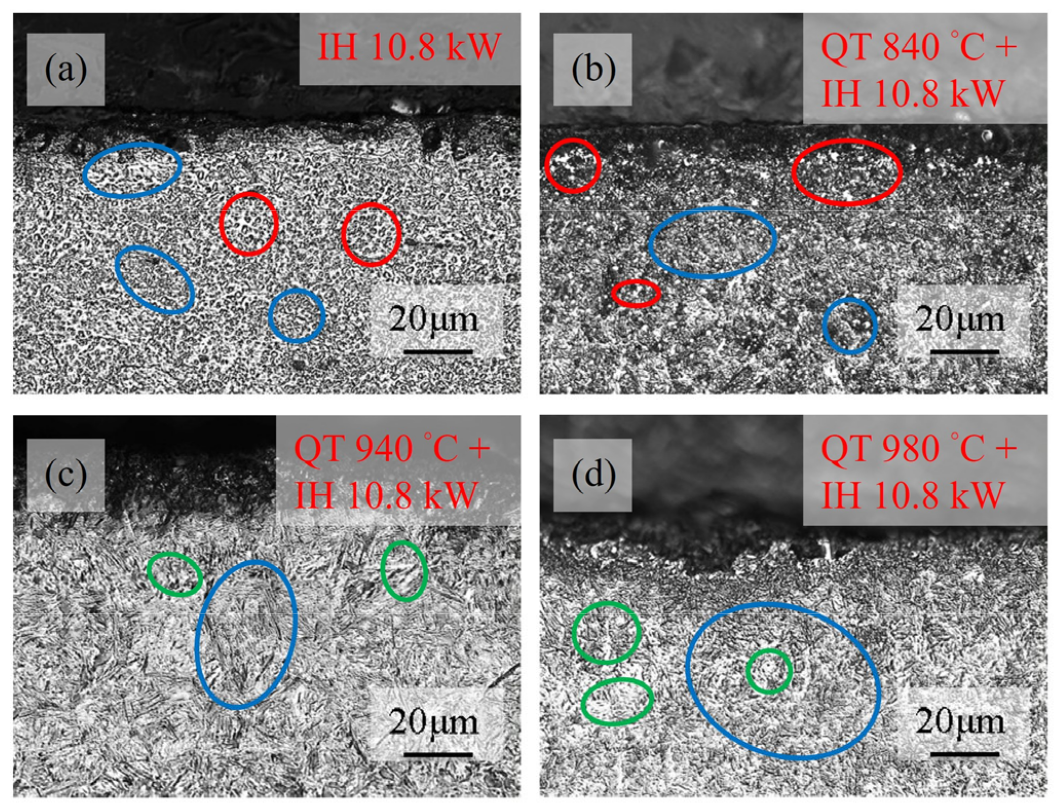
Figure 4 shows the microstructure of the hardened case after induction hardening of the SUJ2 specimen at different states as shown in Figure 3. Figure 4a shows that, if the spheroidized structure is hardened, the microstructure of the case is composed of the cementite that is not completely soluted and dispersed in the tempered martensite matrix. This result shows that the temperature that can be reached when induction hardening is performed at an output power of 10.8 kW may be close to the Acm line. The amount of cementite soluted in austenite is affected by temperature and time. During induction hardening treatment, the temperature holding time is very short, so the temperature raised during induction must be higher to promote the solid-solved effect of cementite.
Figure 4b shows the induction-hardened case in Figure 3b. The result shows the content of cementite in the induction re-hardened case is less than in which the specimen was only held in a salt bath at 840 °C. Figure 4c,d show that the acicular martensite of the case region is clearer than the martensite shown in Figure 3c,d. This is because, during the induction quenching process, there is rapid heating to a higher temperature, resulting in a shorter time for grain growth and a smaller grain size.

3.2. Hardness

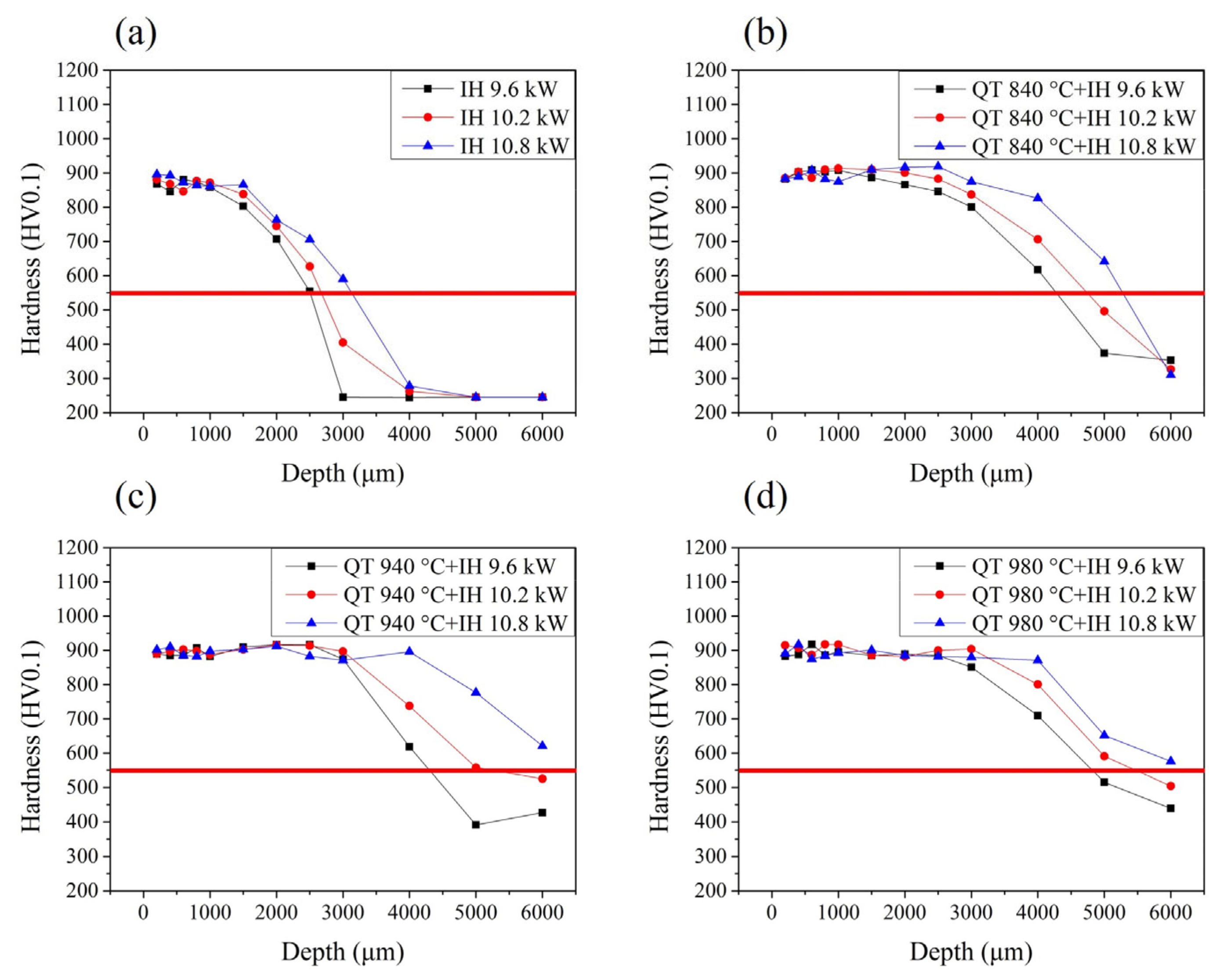
The microhardness curve of the specimens that were induction hardened at different heat treatment states is shown in Figure 5. The distribution of microhardness included a hardened zone, transition region and substrate. Figure 5a represents the microhardness values distribution of SUJ2 steel attained through induction hardening along the depth profiles from surface to substrate. It can be seen that the microhardness value had a relatively high hardness gradient distribution at surface region after induction hardening. This result is in agreement with previous works [30,31]. The hardened zone possessed the highest microhardness value (860–900 HV). According to the needs of industrial use, the depth of 550 HV is set as the effective case depth. For the spheroidized microstructure which was hardened by the induction hardening method at 9.6 kW, the hardness value of the case is 860 HV, and the effective case depth is 2.5 mm. When the induction power is increased to 10.2 kW, the hardness value of the case is 880 HV, and the effective case depth is 2.8 mm. When the induction power is increased to 10.8 kW, the hardness value of the case is 900 HV, and the effective case depth is 3.2 mm. These results show that, as the induction power increases, the hardness value of the case and the effective case depth will be increased relatively. As the power increases, the holding temperature that can be achieved during induction hardening will be higher. Therefore, the hardness value and hardening depth will be increased.
Figure 5b–d shows that a specimen will have a deeper effective case depth when the structure before induction hardening is tempered martensite. For comparison, we discussed the effective case depth of the specimens that were first treated with different austenitizing temperature treatments and used an induction power of 9.6 kW for hardening. The hardness values of the case are all about 900 HV. The effective case depth when austenitized at 840 °C and hardened with induction power is 9.6 kW is 4.2 mm. The effective case depth when austenitized at 940 °C and hardened with induction power 9.6 kW specimen is 4.5 mm. The effective case depth when austenitized at 980 °C and hardened with induction power 9.6 kW is 5.0 mm. This result shows that the effective case depth of induction-hardened specimens was increased with the austenitizing temperature increase. The hardness value obtained when quenching and tempering first to obtain the martensite structure and following that with induction hardening is higher than the hardness value obtained by direct induction hardening of the spheroidized structure. However, the hardness value obtained by induction hardening will not increase due to the increase in austenitized temperature before induction hardening, due to the carbon solution in the austenite being 1.0 wt.%.

3.3. X-ray Diffraction

3.3.1. Residual Stress

The surface residual stress data of the quenched and tempered specimens, austenitized at 840 °C, 940 °C and 980 °C, are shown in Table 2. This indicates that residual compressive stress was observed in the given SUJ2 specimen. The surface residual compressive stress value of the as-received SUJ2 specimen is −77 MPa. However, the surface residual stress appears, as a tensile state was observed in the quenched and tempered specimens austenitized at 840 °C, 940 °C and 980 °C. The surface residual tensile stress value of the specimen austenitized at 840 °C is 106 MPa, for the specimen austenitized at 940 °C is 118 MPa and for the specimen austenitized at 980 °C is 130 MPa. This may be due to the use of a BaCl salt bath for heat treatment. During the salt bath heat treatment process, carbon atoms cannot be effectively prevented from moving out in the surface. The diffusion direction of carbon atoms in the specimens is towards the interface between the salt bath and the specimens. Then the surface residual stress tends to be in a tensile state.
For the quenched and tempered specimen, the contents of the retained austenite austenitized at 940 and 980 °C are 5.1 and 9.0%, respectively, because the carbon content of austenite is 1.0 wt.%.
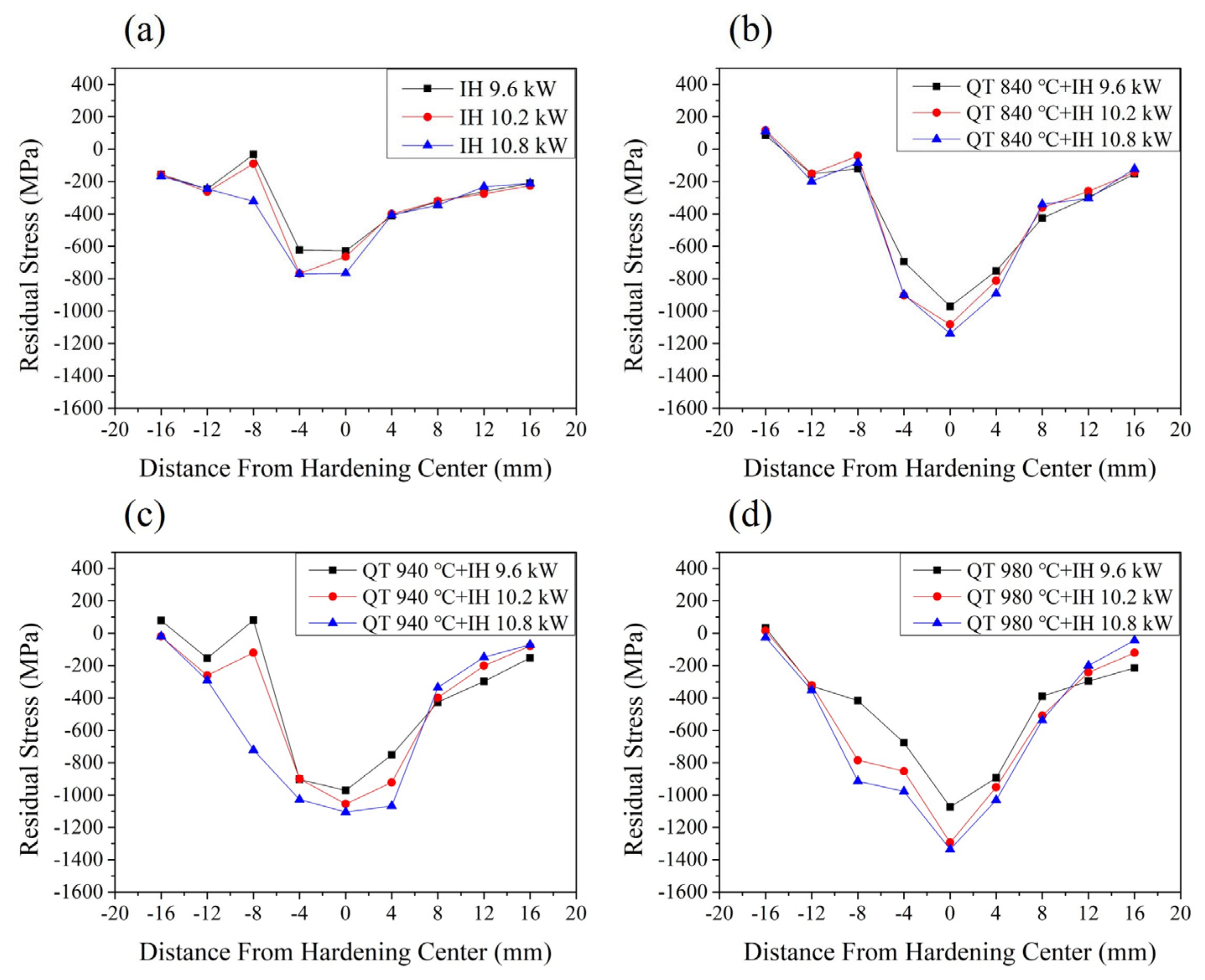
When analyzing the surface residual stress of the induction-hardened specimen, the analyzed position was in the center of the hardened area and along each 4 mm deviation from the center. Figure 6a shows the surface residual stress data of the as-received SUJ2 specimen after induction hardening. It has the highest surface residual compressive stress value at the hardening center, which can be up to −750 MPa. This is because the hardened center by induction will be subject to more severe temperature changes, so the phase transformation caused by the supercooling driving force and the thermal stress caused by the temperature gradient is more effective. As the distance increases from the hardening center, the residual compressive stress value will gradually decrease. As the induction power increases, the surface residual compressive stress value will increase relatively. These results are also related to the temperature gradient during induction hardening. After quenching, the microstructure transforms into martensite due to phase changes. This type of structure changes from FCC to BCT structure, and the volume of parts will expand. The volume expansion generated is hindered by the bulk material, producing compressive residual stresses in the hardened areas. To balance the relatively large compressive residual stress in the outer part, tensile residual stress is built up in the inner part of the specimen [32]. The compressive stresses in the hardened surface rapidly change to tensile stresses within the transition zone. For the specimen hardened by the induction-hardening method at 9.6 kW, the surface residual compressive stress value of the hardening center is −629 MPa. When the induction power increased to 10.2 kW, the surface residual compressive stress value of the hardening center is −663 MPa. With the induction power increased to 10.8 kW, the surface residual compressive stress value of the hardening center is −766 MPa.
Figure 6b–d show a deeper stress influence range when the structure before induction hardening is martensite. The maximum residual compressive stress value in the hardened area will also increase with the austenitized temperature increase. This is because, during the induction hardening process, the specimen is raised to an extremely high temperature in a short time and then cooled rapidly, resulting in a stronger thermal stress effect. The central area of induction hardening is most affected by thermal stress and exhibits the maximum value of residual compressive stress [33]. For comparison, the maximum residual compressive stress value of the specimens quenched with different austenitizing temperature treatments and used an induction power of 9.6 kW for hardening were discussed. The maximum surface residual compressive stress value of the specimen austenitized at 840 °C and re-hardened with an induction power of 9.6 kW specimen is −956 MPa. The maximum surface residual compressive stress value of the specimen austenitized at 940 °C and re-hardened with an induction power of 9.6 kW specimen is −977 MPa. The maximum surface residual compressive stress value of the specimen austenitized at 980 °C and re-hardened with an induction power of 9.6 kW is −1073 MPa.
The residual compressive stress can counteract the tensile stress when the parts are used, so residual compressive stress is considered beneficial to the fatigue strength of the product [19,23]. To meet the needs of industrial use, the surface residual stress specifications of the hardened zone and heat-affected zone must be set to −400 MPa which is set as the compressive stress influence range. The compressive stress influence range of the specimen austenitized at 840 °C and re-hardened with an induction power of 9.6 kW is about 13 mm. The compressive stress influence range at the surface should be compared. The compressive stress influence range of the specimen austenitized at 940 °C and re-hardened with an induction power of 9.6 kW is about 14 mm. The compressive stress influence range of the specimen austenitized at 980 °C and re-hardened with an induction power of 9.6 kW is about 16 mm.

3.3.2. Retained Austenite

The retained austenite is an unstable microstructure and affects the stability of the subsequent use of the parts. Without taking into account the difference in alloy content, carbon steel with a carbon content higher than 0.7 wt.% will obtain its martensite structure after quenching, and is usually accompanied by retained austenite. During use, if this retained austenite is subjected to mechanical or thermal stress, it will easily transform into martensite [8,9], resulting in changes in shape and size (distortion). This will indirectly lead to the premature failure of other parts and cause unnecessary external losses [34].
The surface-retained austenite content data of the quenched and tempered specimens austenitized at 840 °C, 940 °C and 980 °C are shown in Table 2. The results show that no retained austenite content was observed in the SUJ2 specimens which were as-received or austenitized at 840 °C. The surface-retained austenite content of the as-received SUJ2 specimen is 0.2%. The surface-retained austenite content of the specimen austenitized at 840 °C is 0.7%. As the austenitized temperature increases to 940 °C and 980 °C, the amount of cementite solid-solved into the austenite is increased. The increase in carbon content will cause the Ms point to decrease, resulting in quenching (quenched in oil at 90 °C) at the same cooling rate, but there will be a higher retained austenite content of quenched and tempered specimens. The surface-retained austenite content of the specimen austenitized at 940 °C is 5.1%, and for the specimen austenitized at 980 °C is 9.0%.
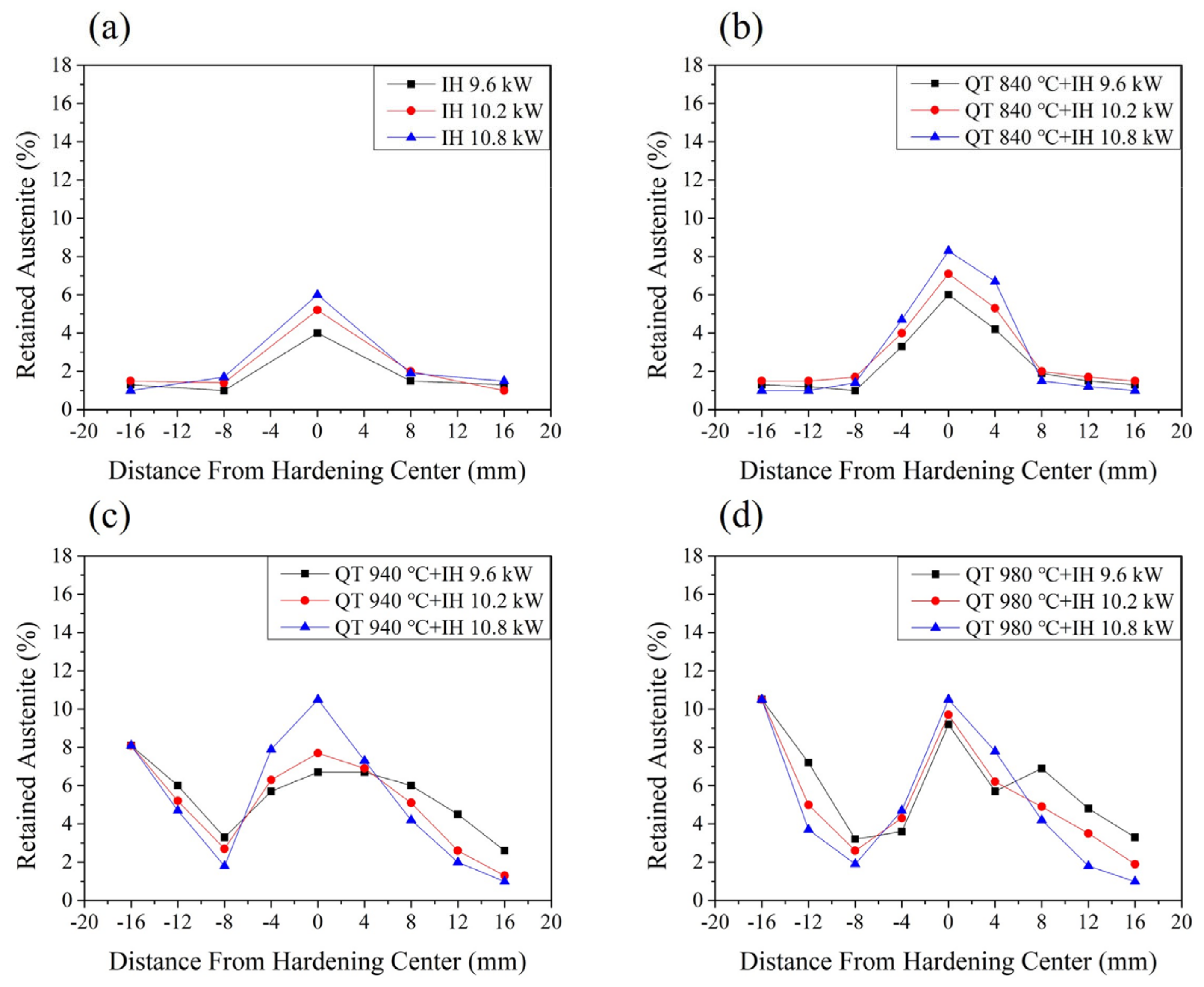
Figure 7a shows the surface-retained austenite content data of the as-received SUJ2 specimen after induction hardening. When the output power increases, the retained austenite content in the hardened area will also increase. This is because the higher the power, the more will the amount of cementite solid-solved in the austenite structure increase during the heating process, and the carbon content in the martensite will also increase after cooling. The as-received specimens treated with a 9.6 kW induction-hardened output power have 3.9% of the retained austenite content in the hardened center. The as-received specimens treated with a 10.2 kW induction-hardened output power have 5.1% of the retained austenite content in the hardened center. The as-received specimens treated with a 10.8 kW induction-hardened output power have 6% of the retained austenite content in the hardened center. As the distance from the hardening center increases, the retained austenite content will gradually decrease. This is because, in the heat-affected zone, the temperature raised during induction hardening may not reach the A1 line. Therefore, no retained austenite will be measured in the heat-affected zone after induction treatment.
Figure 7b–d shows a higher retained austenite content at the hardening center than the specimen austenitized at 840 °C, 940 °C and 980 °C. The reason for this is that the proportion of cementite solid-solved into the martensite matrix increases after induction re-hardening [29,30]. Therefore, due to the difference in carbon content within the martensite structure, there is a higher retained austenite content in the re-hardened area. The maximum retained austenite content in the hardened area will also increase with the austenitized temperature increase. In addition, the retained austenite in the heat-affected zone can be eliminated to a minimum of 2%. As mentioned before, the heat-affected zone rises to a lower temperature (lower than the temperature of the A1 line) during induction hardening. After induction re-hardening, it has a similar high-temperature tempering effect of eliminating retained austenite, so the content of retained austenite measured in the heat-affected zone will be less.

4. Conclusions

  • The microstructure of the material before induction hardening has a significant impact on the effective case depth under the same output power conditions. The effective case depth of the tempered martensite structure after induction hardening is deeper than that of the spheroidized structure. The spheroidized structure was treated by the induction hardening method at 9.6 kW, and its effective case depth was only 2.5 mm. If the microstructure is tempered martensite before induction-re-hardening treatment, the effective case depth of the induction-hardened specimens with an induction power of 9.6 kW can be increased to 4.2 mm.
  • Because the hardened center by induction method will be subject to more severe temperature changes, the phase transformation caused by the supercooling driving force and the thermal stress caused by the temperature gradient is more effective. The hardened center area during induction hardening has the highest residual compressive stress value. The specimen was hardened by the induction-hardening method at 10.8 kW and the surface residual compressive stress value of the hardening center was able to reach −766 MPa. As the distance from the hardening center increases, the residual compressive stress value will gradually decrease.
  • During the induction hardening process, the phase transformation of the martensite structure caused more internal stress due to hardening treatment. The maximum surface residual compressive stress value of the specimen that was austenitized at 980 °C and induction hardened with an induction power of 9.6 kW specimen is −1073 MPa.
  • The SUJ2 specimen that will have a wider stress influence range under the condition of the microstructure before induction hardening is that of tempered martensite. The effective stress influence range of the induction-hardened specimen austenitized at 980 °C and induction hardened with an induction power of 9.6 kW can reach 16 mm.
  • The heat-affected zone is lower than the hardened center region during induction hardening. The content of retained austenite measured in the heat-affected zone will be less. The retained austenite in the heat-affected zone can be decreased from 9% to a minimum of 2%.

Author Contributions

Conceptualization, S.-Q.L.; methodology, S.-Q.L. and L.-H.C.; formal analysis, S.-Q.L. and L.-H.C.; investigation, S.-Q.L.; data curation, S.-Q.L.; writing—original draft, S.-Q.L.; writing—review and editing, S.-Q.L. and L.-H.C. All authors have read and agreed to the published version of the manuscript.

Funding

This research received no external funding.

Data Availability Statement

Data are contained within the article.

Acknowledgments

The authors would like to thank Tatung University (B113-M02-013) in Taiwan (ROC) for the funding support.

Conflicts of Interest

The authors declare no conflict of interest.

References

  1. Fernandes, A.P.; Gallego, J.; Picon, C.A.; Filho, G.T.; Casteletti, L.C. Wear and corrosion of niobium carbide coated AISI 52100 bearing steel. Surf. Coat. Technol. 2015, 279, 112–117. [Google Scholar] [CrossRef]
  2. Hisakado, T.; Miura, K.; Suda, H. Effects of debris transfer and abrasive particle damage on the abrasive wear of hardened bearing steel. Wear 2001, 247, 24–32. [Google Scholar] [CrossRef]
  3. Matsunaga, H.; Komata, H.; Yamabe, J.; Fukushima, Y.; Matsuoka, S. Effect of Size and Depth of Small Defect on the Rolling Contact Fatigue Strength of Bearing Steel JIS-SUJ2. Procedia Mater. Sci. 2014, 3, 1663–1668. [Google Scholar] [CrossRef]
  4. Hwang, H.; De Cooman, B.C. Influence of the initial microstructure on the spheroidization of SAE 52100 bearing steel. Steel Res. Int. 2016, 87, 112–125. [Google Scholar] [CrossRef]
  5. Sun, J.; Wood, R.J.K.; Wang, L.; Care, I.; Powrie, H.E.G. Wear monitoring of bearing steel using electrostatic and acoustic emission techniques. Wear 2005, 259, 1482–1489. [Google Scholar] [CrossRef]
  6. Rivero, I.V.; Ruud, C.O. Deviation of residual stress patterns in 52100 bearing steel due to inherent microstructural transformations after rolling contact. Mater. Charact. 2004, 53, 381–393. [Google Scholar] [CrossRef]
  7. Roy, S.; Sundararajan, S. Effect of retained austenite on spalling behavior of carburized AISI 8620 steel under boundary lubrication. J. Mater. Res. Technol. 2019, 119, 238–246. [Google Scholar] [CrossRef]
  8. Šmeļova, V.; Schwedt, A.; Wang, L.; Holweger, W.; Mayer, J. Electron microscopy investigations of microstructural alterations due to classical rolling contact fatigue (RCF) in martensitic AISI 52100 bearing steel. Int. J. Fatigue 2017, 98, 142–154. [Google Scholar] [CrossRef]
  9. Ostermayer, P.; Burkart, K.; Blinn, B.; Surm, H.; Clausen, B.; Beck, T. Evaluation of the plastic deformation behavior of modified 100Cr6 steels with increased fractions of retained austenite using cyclic indentation tests. Mater. Test. 2022, 64, 1298–1312. [Google Scholar] [CrossRef]
  10. Huang, M.S.; Huang, Y.L. Effect of multi-layered induction coils on efficiency and uniformity of surface heating. Int. J. Heat Mass Transf. 2010, 53, 2414–2423. [Google Scholar] [CrossRef]
  11. Cao, Y.J.; Sun, J.Q.; Ma, F.; Chen, Y.Y.; Cheng, X.Z.; Gao, X.; Xie, K. Effect of the microstructure and residual stress on tribological behavior of induction hardened GCr15 steel. Tribol. Int. 2017, 115, 108–115. [Google Scholar] [CrossRef]
  12. Torkamani, H.; Vrček, A.; Larsson, R.; Antti, M.L. Micro-pitting and wear damage characterization of through hardened 100Cr6 and surface induction hardened C56E2 bearing steels. Wear 2022, 492–493, 204218. [Google Scholar] [CrossRef]
  13. Schüßler, P.; Damon, J.; Mühl, F.; Dietrich, S.; Schulze, V. Laser surface hardening: A simulative study of tempering mechanisms on hardness and residual stress. Comput. Mater. Sci. 2023, 221, 112079. [Google Scholar] [CrossRef]
  14. Li, H.P.; Sun, Y.; He, L.F.; Li, Z.C. Failure analysis of ball screw in the progressive induction hardening and finishing machining. Eng. Fail. Anal. 2023, 151, 107410. [Google Scholar] [CrossRef]
  15. Mühl, F.; Damon, J.; Dietrich, S.; Schulze, V. Simulation of induction hardening: Simulative sensitivity analysis with respect to material parameters and the surface layer state. Comput. Mater. Sci. 2020, 184, 109916. [Google Scholar] [CrossRef]
  16. Areitioaurtena, M.; Segurajauregi, U.; Fisk, M.; Cabello, M.J.; Ukar, E. Influence of induction hardening residual stresses on rolling contact fatigue lifetime. Int. J. Fatigue 2022, 23, 106781. [Google Scholar] [CrossRef]
  17. Hu, Y.; Qin, Q.; Wu, S.; Zhao, X.; Wang, W. Fatigue resistance and remaining life assessment of induction-hardened S38C steel railway axles. Int. J. Fatigue 2021, 144, 106068. [Google Scholar] [CrossRef]
  18. Gao, J.W.; Pan, X.N.; Han, J.; Zhu, S.P.; Liao, D.; Li, Y.B.; Dai, G.Z. Influence of artificial defects on fatigue strength of induction hardened S38C axles. Int. J. Fatigue 2020, 139, 105746. [Google Scholar] [CrossRef]
  19. Hayama, M.; Kikuchi, S.; Tsukahara, M.; Misaka, Y.; Komotori, J. Estimation of residual stress relaxation in low alloy steel with different hardness during fatigue by in situ X-ray measurement. Int. J. Fatigue 2024, 178, 107989. [Google Scholar] [CrossRef]
  20. Li, B.Z.; Jiang, X.H.; Yang, J.G.; Liang, S.Y. Effects of depth of cut on the redistribution of residual stress and distortion during the milling of thin-walled part. J. Mater. Process. Technol. 2015, 216, 223–233. [Google Scholar] [CrossRef]
  21. Rech, J.; Kermouche, G.; Grzesik, W.; Garcia-Rosales, C.; Khellouki, A.; Garcia-Navas, V. Characterization and modelling of the residual stresses induced by belt finishing on a AISI52100 hardened steel. J. Mater. Process. Technol. 2008, 208, 187–195. [Google Scholar] [CrossRef]
  22. Silveira, E.; Irisarri, A.M. Study on the distortion of steel worm shafts. Eng. Fail. Anal. 2009, 16, 1090–1096. [Google Scholar] [CrossRef]
  23. Xiao, G.; Chen, B.; Li, S.; Zhuo, X. Fatigue life analysis of aero-engine blades for abrasive belt grinding considering residual stress. Eng. Fail. Anal. 2022, 131, 105846. [Google Scholar] [CrossRef]
  24. Ao, S.S.; Li, C.J.; Huang, Y.F.; Luo, Z. Determination of residual stress in resistance spot-welded joint by a novel X-ray diffraction. Measurement 2020, 161, 107892. [Google Scholar] [CrossRef]
  25. Tanaka, K. The cosα method for X-ray residual stress measurement using two-dimensional detector. Mech. Eng. Rev. 2019, 6, 378. [Google Scholar] [CrossRef]
  26. ASTM E975-13; Standard Practice for X-ray Determination of Retained Austenite in Steel with Near Random Crystallographic Orientation. ASTM International: West Conshohocken, PA, USA, 2013.
  27. Zhang, C.L.; Liu, X.; Zhang, D.; Xie, L.Y.; Zhou, L.Y.; Liu, Y.Z. Carbide inheritance of pearlite spheroidization during heat treatment process in GCr15 steel. Trans. Mater. Heat Treat. 2014, 35, 45–48. [Google Scholar]
  28. Wang, Z.N.; Cui, H.Z.; Zhang, G.S.; Wang, W.; Sun, J.Q.; Cheng, G.Q. Microstructure and room-temperature dry sliding wear behavior of GCr15 steel treated by surface induction hardening. Trans. Mater. Heat Treat. 2015, 36, 180–187. [Google Scholar]
  29. Bhadeshia, H.K.D.H. Steels for bearings. Prog. Mater. Sci. 2012, 57, 268–435. [Google Scholar] [CrossRef]
  30. Li, G.; Xiang, J.; Kuang, J.; Jia, M.D. Microstructure and properties of GCr15 steel treated by laser quenching. Trans. Mater. Heat Treat. 2010, 31, 129–132. [Google Scholar]
  31. Gai, Y.H.; Yan, Y.; Li, C.N.; Li, B.M.; Du, W.; Li, M.S. Fatigue test and failure analysis of Cr Mo steel ball screw pair. Trans. Mater. Heat Treat. 2015, 36, 148–155. [Google Scholar]
  32. Holmberg, J.; Steuwer, A.; Stormvinter, A.; Kristoffersen, H.; Haakanen, M.; Berglund, J. Residual stress state in an induction hardened steel bar determined by synchrotron- and neutron diffraction compared to results from lab-XRD. Mater. Sci. Eng. A 2016, 667, 199–207. [Google Scholar] [CrossRef]
  33. Yi, J.; Gharghouri, M.; Bocher, P.; Medraj, M. Distortion and residual stress measurements of induction hardened AISI 4340 discs. Mater. Chem. Phys. 2013, 142, 248–258. [Google Scholar] [CrossRef]
  34. Cui, W.; San-Martín, D.; Rivera-Díaz-del-Castillo, P.E.J. Stability of retained austenite in martensitic high carbon steels. Part I: Thermal stability. Mater. Sci. Eng. 2018, 711, 683–695. [Google Scholar] [CrossRef]
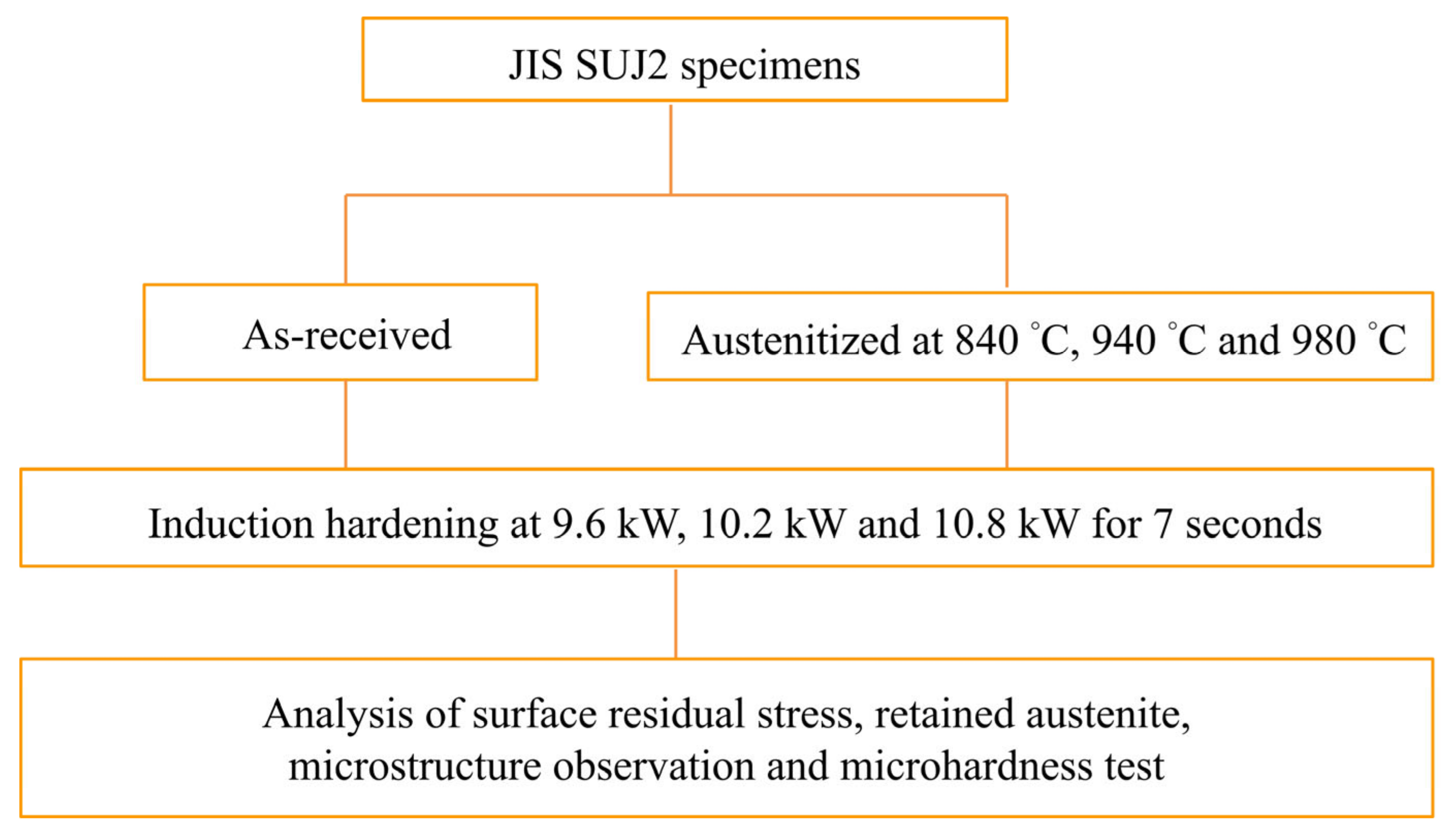
Figure 1. Graphical abstract of this study.
Metals 14 00201 g001
Figure 2. The schematic diagram of the experiment device.
Metals 14 00201 g002
Figure 3. Core microstructure of SUJ2 specimens that were (a) as-received and quenched at (b) 840 °C, (c) 940 °C and (d) 980 °C. Black circle: Ferrite, Red circle: Cementite, Blue circle: Martensite, Green circle: Retained Austenite.
Metals 14 00201 g003
Figure 4. Surface microstructure of SUJ2 specimens with induction quenching by a power of 10.8 kW for specimens that were (a) as-received and quenched (b) at 840 °C, (c) 940 °C and (d) 980 °C. Red circle: Cementite, Blue circle: Martensite, Green circle: Retained Austenite.
Metals 14 00201 g004
Figure 5. Hardness profile of induction-hardened SUJ2 specimens for specimens that were (a) as-received and quenched (b) at 840 °C, (c) 940 °C and (d) 980 °C. Red line: the depth of 550 HV is set as the effective case depth.
Metals 14 00201 g005
Figure 6. Residual stress profiles of induction-hardened SUJ2 specimens that were (a) as-received and quenched at (b) 840 °C, (c) 940 °C and (d) 980 °C.
Metals 14 00201 g006
Figure 7. Retained austenite profile of induction-hardened SUJ2 specimens that were (a) as-received and quenched at (b) 840 °C, (c) 940 °C and (d) 980 °C.
Metals 14 00201 g007
Table 1. Chemical composition of the JIS SUJ2 specimens in the study (wt.%).
CSiMnPCrNiCuFe
1.050.2430.4260.02010.01470.09480.101Bal.
Table 2. Hardness (HRC), residual stress (RS) and retained austenite (γ) data of the SUJ2 specimen in a quenched and tempered state (QT).
As-Received840 °C QT *940 °C QT *980 °C QT *
HRC19 ± 160 ± 160 ± 160 ± 1
RS (MPa)−77106118130
γ (%)0.20.75.19.0
* Austenitized at three different temperatures of 840 °C, 940 °C and 980 °C for 1 h in salt bath, quenched in oil at 90 °C and then tempered at 180 °C for 1 h.
Disclaimer/Publisher’s Note: The statements, opinions and data contained in all publications are solely those of the individual author(s) and contributor(s) and not of MDPI and/or the editor(s). MDPI and/or the editor(s) disclaim responsibility for any injury to people or property resulting from any ideas, methods, instructions or products referred to in the content.