Article

Heterogeneous Microstructure and Tensile Properties of an Austenitic Stainless Steel

1
College of Materials Science and Engineering, Fujian University of Technology, Fuzhou 350118, China
2
Fujian Provincial Key Laboratory of New Material Preparation and Forming Technology, Fuzhou 350118, China
*
Author to whom correspondence should be addressed.
Metals 2024, 14(3), 285; https://doi.org/10.3390/met14030285
Submission received: 17 January 2024 / Revised: 17 February 2024 / Accepted: 19 February 2024 / Published: 29 February 2024

Abstract

:
Stainless steel (SS) exhibits excellent ductility; however, its low strength hinders its practical applications. To achieve good synergy between strength and ductility, a heterogeneous structure was introduced into a newly developed nitrogen-alloyed low-nickel austenitic steel, QN1803. The received QN1803 was cold-rolled and annealed at 993 K for different durations, and the microstructural evolution and tensile mechanical properties were investigated. The yield strength (1130 MPa) of the QN1803 annealed at a temperature of 993 K for 15 min was approximately three times higher than that of the as-received sample (314 MPa). The short annealing time of 15 min yielded a heterogeneous structure with grain size distributions ranging from nanoscale to micron-scale. The annealed QN1803 exhibited typical dislocation cells and dislocation walls caused by slipping after cold rolling. During annealing, a step-like lamellar structure is formed. The high yield strength was obtained from the large number of twins and hard ultrafine grains. The good ductility is due to the large number of dislocations generated in the soft grains and the GNDs around the heterogeneous interfaces. Additionally, the lamella structure of the material also contributes to improved ductility to a certain degree. The aim of this paper is to develop new materials with both high yield strength and excellent toughness based on more economical materials cost.

1. Introduction

Austenitic stainless steels are widely used in industry and in daily life owing to their excellent corrosion resistance and ductility. Traditional austenitic stainless steel contains a large amount of Ni, which not only improves its corrosion resistance and mechanical properties but also its thermal stability and weldability. However, Ni is expensive; thus, cost reduction is an important concern. Owing to the low price of N, which stabilizes austenite [1], strengthens the solid solution, and reduces the stacking fault energy [2], it can replace Ni to some extent. He et al. achieved significant interstitial solid solution strengthening by employing heavy N- doping and reducing the content of expensive Ni and Co. The organization possesses profuse fine laths and a minor fraction of submicron-sized recrystallized grains with nano nitrides [3]. Therefore, the development of nickel-saving austenitic stainless steel has the significance of resource saving, cost reduction, broadening application areas, and environmental friendliness, which are important for the stainless steel industry and sustainable development. QN1803 stainless steel is a new type of nitrogen-alloyed nickel-saving austenitic stainless steel, which was developed by partially substituting nickel with nitrogen. QN1803 stainless steel reduces the need for expensive metal Ni [4] and has the advantages of low cost, high ductility, and good corrosion resistance [5]. However, its low yield strength (200–400 MPa) severely limits its engineering applications.
In recent years, the capability of heterostructured materials to simultaneously improve their strength and plasticity has attracted considerable attention from researchers.
Some heterostructures, such as bimodal structures [6,7], gradient structures (GS) [8,9,10], layer structures (LS) [11,12], and harmonic structures [13], have been designed to effectively improve the strength–ductility synergy. Heterostructured materials have the characteristics of both soft and hard domains. During tensile deformation, owing to the poor plasticity of the hard domains, when the soft domains begin plastic deformation, the hard domains maintain elastic deformation, and the resulting dislocations accumulate at the boundary. This type of long-range stress is called back stress, which acts in the direction opposite to the applied stress. Back stress interferes with the movement of dislocations in soft domains and improves the strength of the material [14]. When the soft domains and the hard domains are plastically deformed together because the soft domains and hard domains endure different strains (the plastic strain on the soft domains is higher than that on the hard domains), a strain gradient is generated at the interface to adapt the stress and strain. The strain gradient is adjusted by geometrically necessary dislocations (GNDs) [15]. The back stress generated serves to enhance the strain hardening ability, thereby preserving the material’s ductility [14]. The essence of back-stress reinforcement of heterogeneous materials is to improve the mechanical properties of nonhomogeneous materials by changing the interface density between the soft and hard domains [14,16,17], as well as by maximizing the strain/stress distribution and strain gradient between regions [16]. He et al. [18] investigated medium-Mn steel produced by multiple deformations and annealing and developed a steel with metastable austenite grains embedded in a highly dislocated martensite matrix. The steel exhibited a very high strength of over 2 GPa with a ductility of over 10%. This is mainly due to the increased plastic deformation of the steel through low-temperature rolling, which creates an uneven strain energy/dislocation density in steel [19]. Yan et al. [20] investigated 316 L SS with a heterogeneous structure in which static recrystallized grains were embedded within nanograin and showed good synergy of yield strength (~1.0 GPa) and ductility (~27% uniform elongation). Similarly, Niu et al. [21] obtained stainless steel with a heterogeneous lamellar microstructure by cold rolling and flash annealing, which exhibited ultrahigh yield strength (~1.4 GPa) and high ductility (~37% uniform elongation). Therefore, the preparation of heterostructures in stainless steels is an effective approach to achieving excellent strength–ductility synergy.
In this study, a combination of cold rolling and annealing has been used to introduce a heterogeneous microstructure into the austenitic stainless steel QN1803. The evolution of the heterogeneous grain structures with different holding times was studied, and their effects on the mechanical properties were discussed.

2. Materials and Methods

Commercial QN1803 austenitic stainless steel (QN1803) with the composition listed in Table 1 was used to study the mechanical properties after cold rolling and annealing. The QN1803 sheet was cut into 35 × 10 × 4.5 mm3 blocks. The surfaces of the cuboid samples were ground, polished, cleaned, dried, and subjected to cold rolling (CR) at 350 mm/s using a two-stick rolling mill. During CR, an average thickness reduction of 0.5 mm was achieved each time, and the average thickness was reduced by 60% from 4.5 mm to 1.8 mm after cold rolling. The cold-rolled alloy samples were subsequently annealed at 993 K for 15 min, 25 min, and 60 min and then quenched into water; these were denoted as A15, A25, and A60, respectively.
The microstructures of the cold-rolled samples after different annealing times were characterized (transverse direction) by scanning electron microscopy (SEM, FEI Nova Nano SEM 450, Hillsborough, OR, USA), electron backscatter diffraction (EBSD, Oxford Aztec) at 20 kV, and transmission electron microscopy (TEM, JEM-2100, 200 KV, Manufacturer, Tokyo, Japan). The SEM sample was mechanically ground and polished with SiC sandpaper until the surface was free of scratches and then corroded with aqua regia (75% hydrochloric acid: 25% nitric acid). The EBSD samples were prepared by electrolytic polishing in an acetic acid (77%)–perchloric acid (23%) solution. The step size of the EBSD measurement was 0.2. An X-ray diffractometer (XRD, D8Advance, Karlsruhe, Germany) was used to determine the phase structures of the samples. The tube current was 40 mA, the voltage was 40 kV, the scanning range was 40–100°, the scanning rate was 6°/min, and the X-ray wavelength was 0.15406 nm. Considering the strength of austenite and martensite peaks, the following semiempirical formula was used to calculate the volume fraction of martensite [22,23]: f a = I 110 a I 110 a + 0.65 I 111 γ + I 200 γ . The hardness was measured using a micro-Vickers hardness tester (HVST-10, China). Each sample was measured seven times; the test load was 300 g, and the loading time was 10 s. Of the final test results, the maximum and minimum values were eliminated, and the average values were used. Room-temperature tensile tests (298 K) were performed on a universal testing machine (INSTRON2382, Norwood, MA, USA). A bone-shaped tensile sample with a gauge size of 10 × 2 × 1 mm3 was cut along the rolling direction. And a tensile rate of was 1 × 10⁻³ s−1. To guarantee the correctness of the data, each test was performed thrice under the same conditions.

3. Results

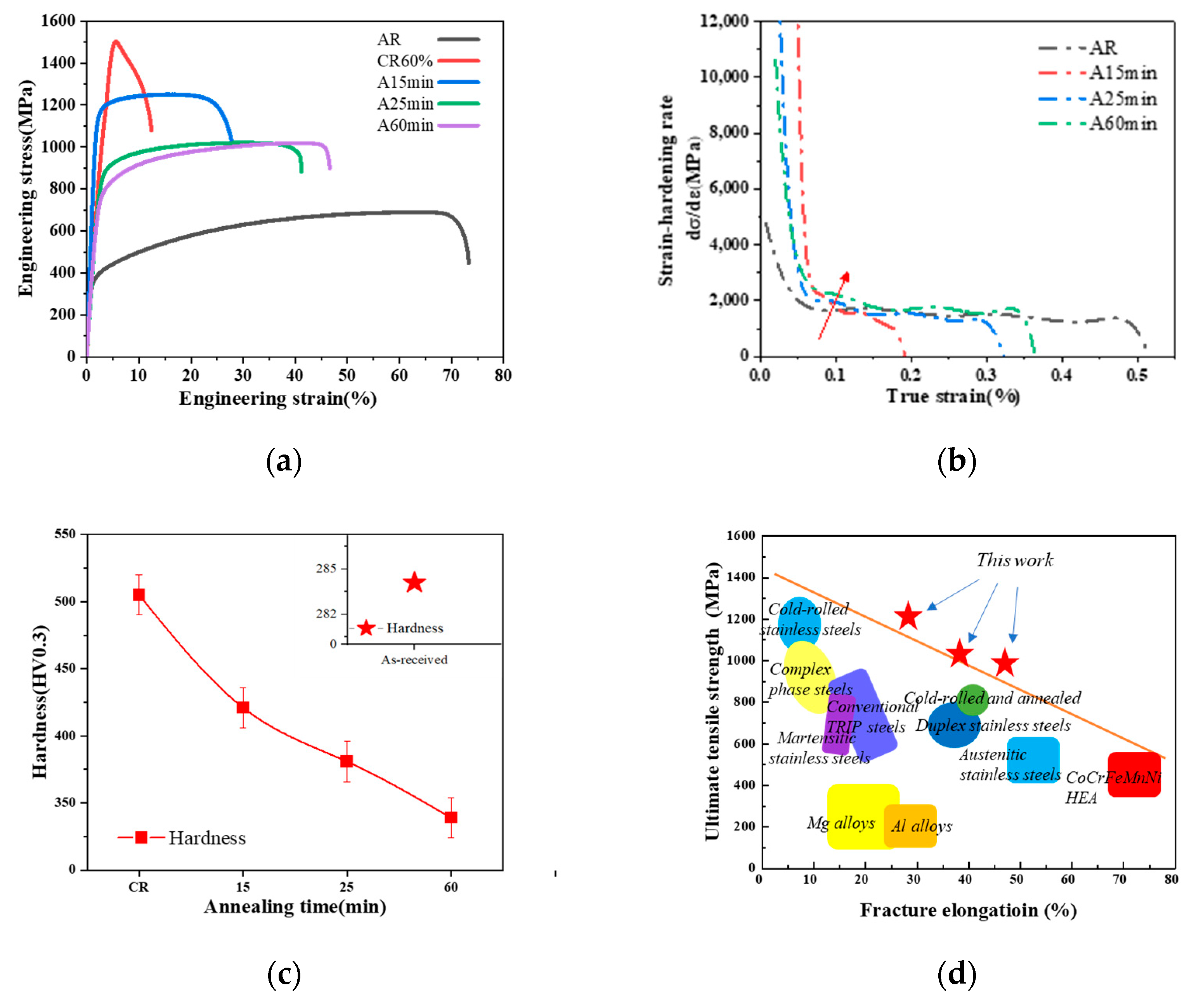
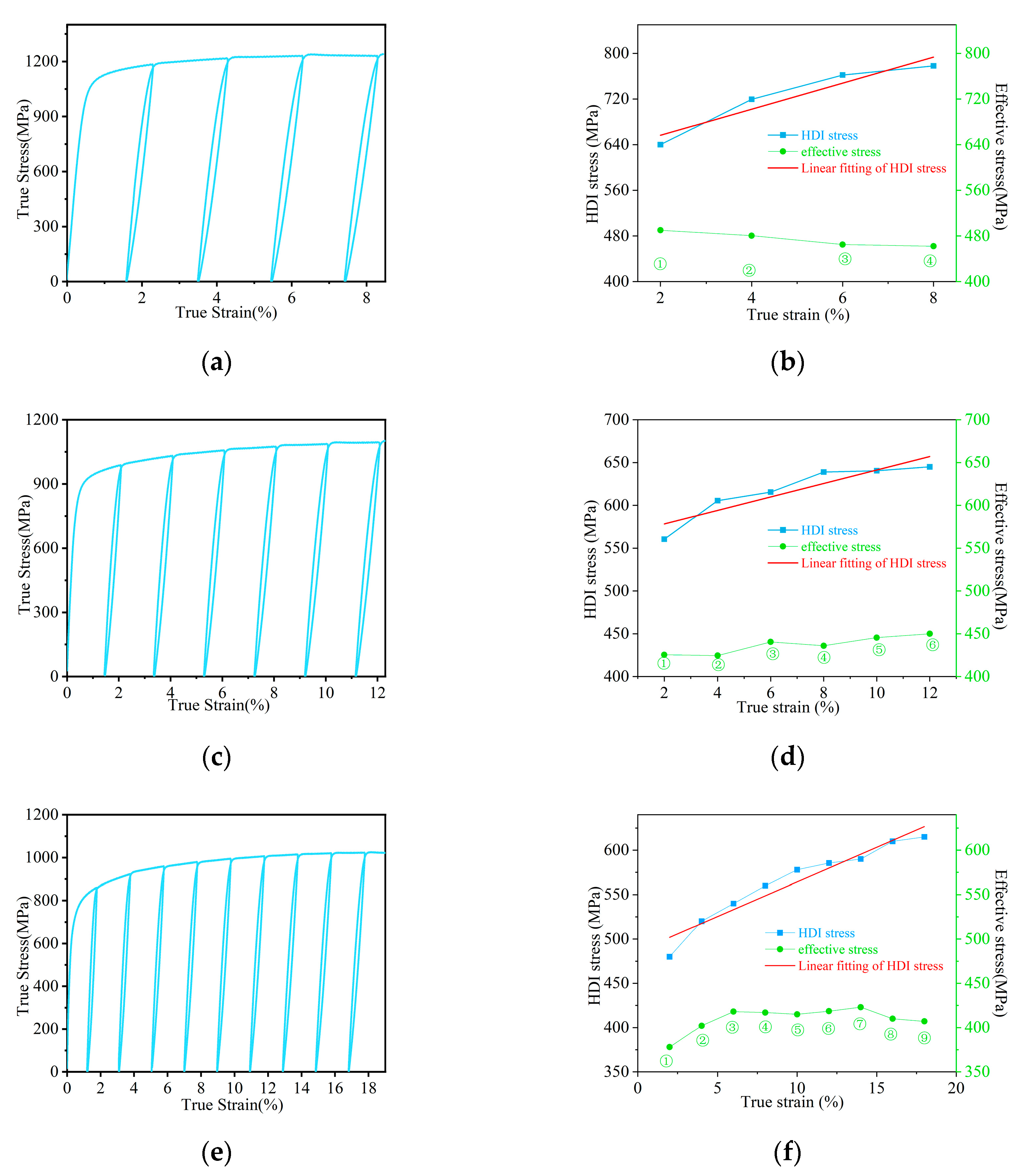
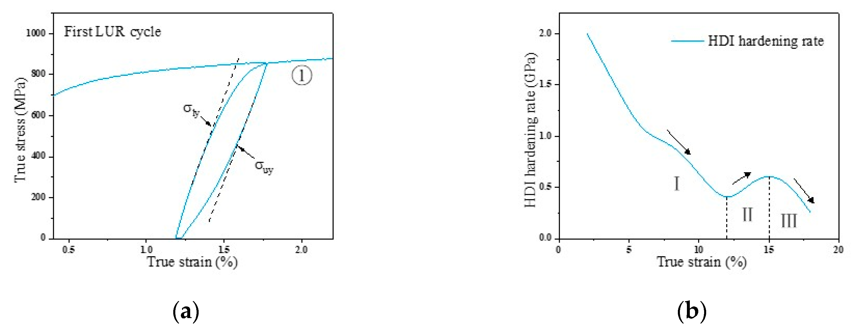
3.1. Mechanical Properties
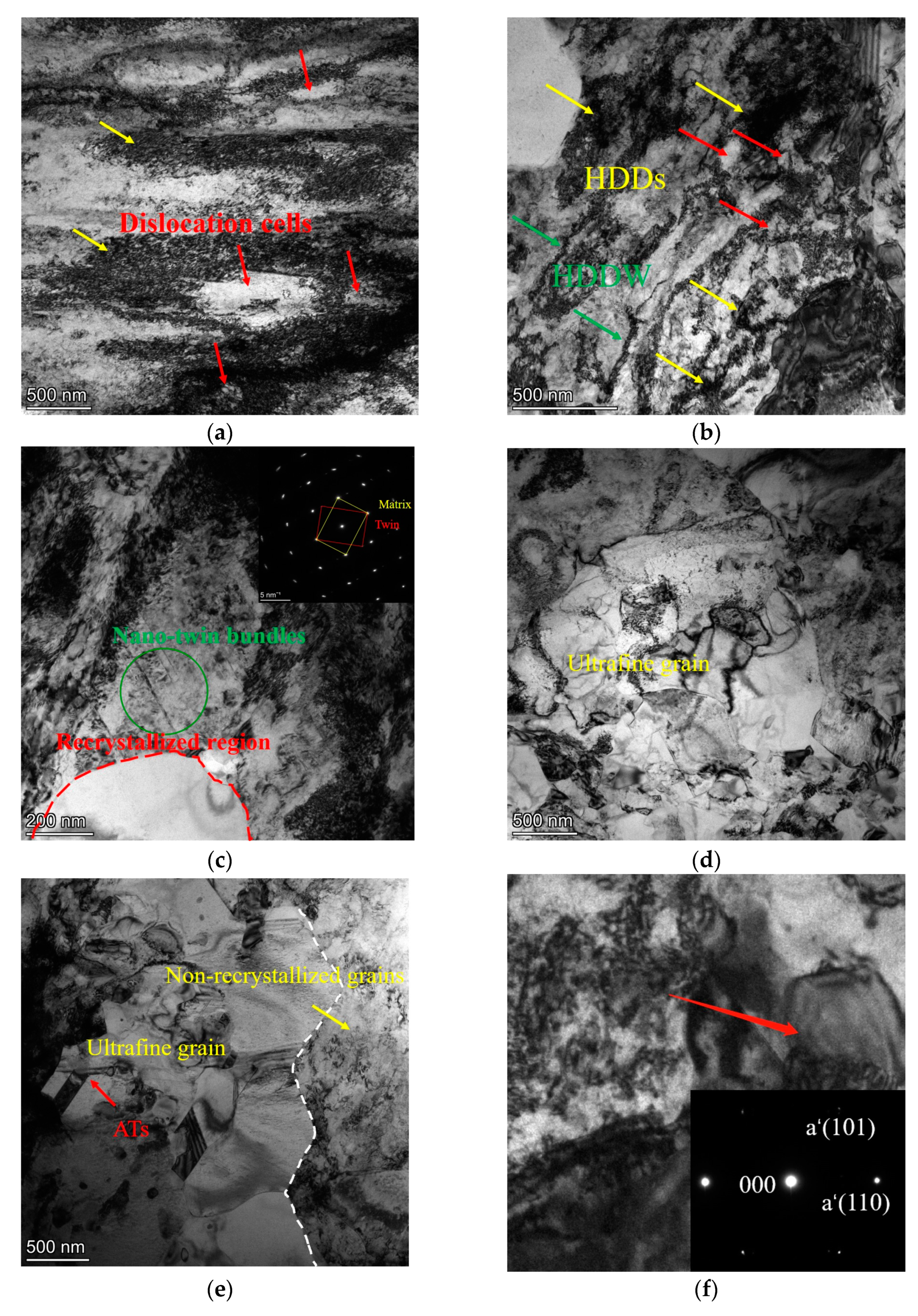
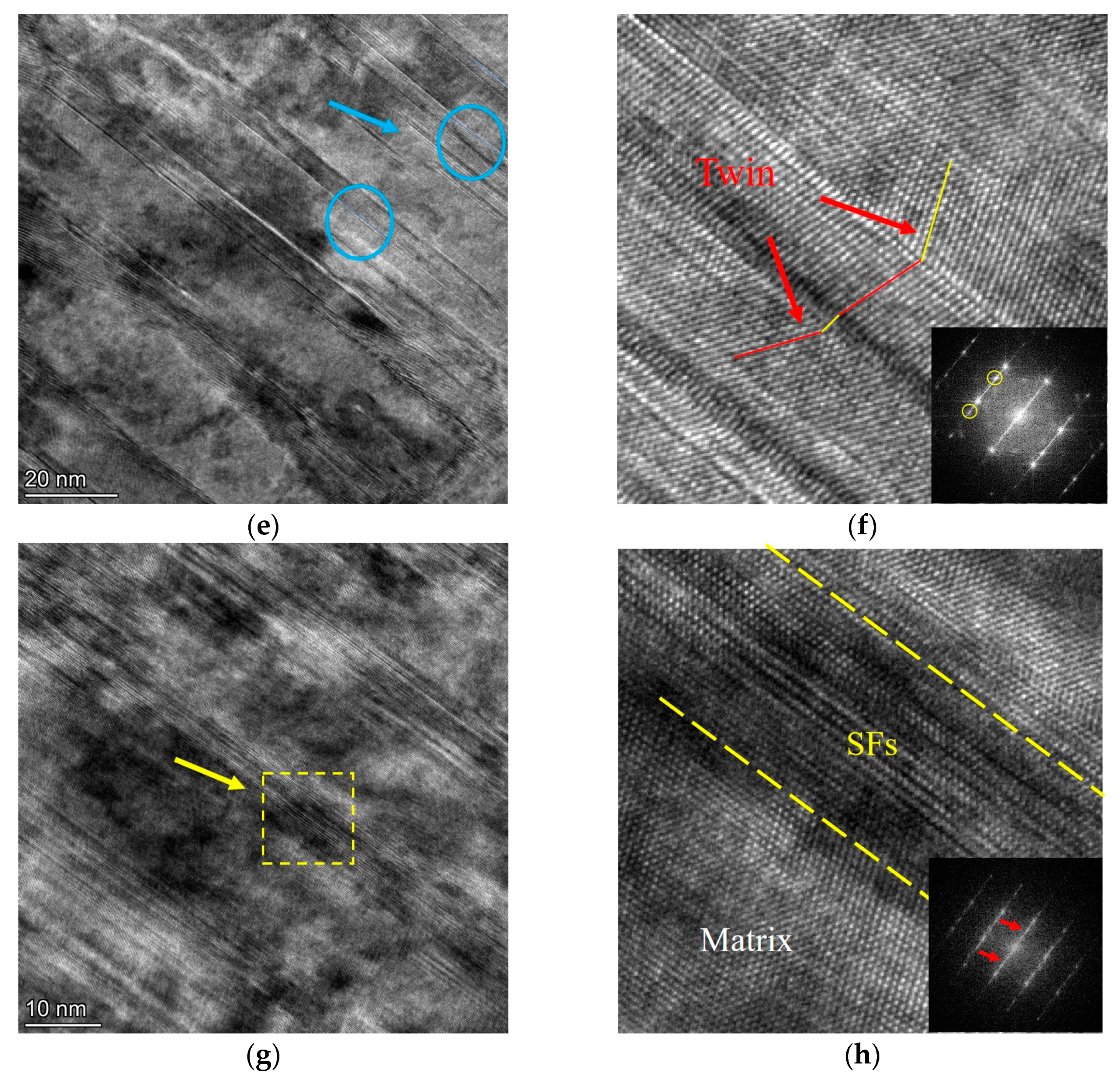
The uniaxial tensile engineering stress–strain curves of QN1803 at different annealing times are shown in Figure 1a. The As-received (AR) samples had a low yield strength and high ductility; the maximum ductility was almost 70%, whereas the yield strength was less than 400 MPa. After 60% cold rolling, the yield strength increased significantly from 350 to 1500 MPa, three times that of the AR sample. However, its tensile plasticity was poor, and its uniform elongation was only 1%. With an increase in annealing time, the tensile ductility increased significantly while the strength decreased. The samples annealed for 15 min exhibited good strength and ductility. The yield and tensile strengths reach approximately 1130 MPa and 1250 MPa, respectively. Uniform elongation and elongation at break were approximately 15% and 28%, respectively. When the annealing time was 60 min, most of the grains were completely recrystallized; their yield and tensile strengths were greater than 700 MPa and 900 MPa, respectively, and the uniform elongation was greater than 40%.
Figure 1b shows the corresponding strain hardening rate (SHR) curves. The SHR of all samples exhibited a sharp decrease to 2000 at the start of plastic deformation, followed by a slow decline. The results of the study showed that A60 samples have a greater strain hardening capacity than the other samples. Figure 1c shows the results of the Vickers hardness test. The data in the upper-right corner shows the initial hardness of the as-received sample, which was approximately 284 HV. After cold rolling, the hardness of the sample increased rapidly to approximately 505 HV. When the annealing time increased to 15 min, the hardness decreased slightly to 421 HV.
Figure 1d compares the tensile properties of the present alloy with other alloys at room temperature. The data indicates that the present alloy exhibits superior strength/ductility synergy.
The tensile fracture surfaces of the samples are shown in Figure 2. The as-received samples had round and oval dimples that were uniformly distributed in a honeycomb shape and belonged to a typical ductile fracture (Figure 2a). The cold-rolled samples mainly exhibited transgranular fractures, and the dimples almost disappeared, indicating brittle fractures (Figure 2b). With an increase in the annealing time, the number of dimples gradually increased, indicating that the plasticity gradually increased. This trend was consistent with the tensile test results shown in Figure 1a. It has been reported that increasing the annealing time increased the dimple size and ductility of the sample [24]. In addition, the fracture surface of the annealed sample is characterized by delamination along the transverse direction (as indicated by the black arrow in Figure 2), which is very similar to the fracture morphology of the other layered structure samples. Some studies have shown that this delamination fracture mode can improve the toughness of steel plates [25], which is an important reason for the necking of A25 alloys. As shown in Figure 2d–f, the fracture surface is similar to a stepped shape, and these stepped surfaces are cut off perpendicular to the rolling direction. There were also small dimples in the fracture morphology of the horizontal stepped plane shown in Figure 2e; therefore, the sample annealed after rolling exhibited a necking phenomenon.

3.2. Microstructure

Figure 3a shows the XRD patterns of the as-received (AR), cold-rolled (CR60), and cold-rolled and annealed alloys (A15, A25, A60). The AR sample comprises a single face-centered cubic (FCC) phase. With 60% cold rolling, the austenitic phase peak decreased, and a martensite peak (a’(110)) began to appear. This will be demonstrated in the subsequent TEM. After annealing at 993 K, the austenitic phase gradually increased, and the intensity of the martensite peak (a’(110)) decreased. The phase volume fraction was calculated using a semiempirical formula. Therefore, the fraction of martensite formed by deformation can be roughly estimated via XRD analysis. The XRD pattern in Figure 1a shows that the AR alloys were completely austenitic. Figure 1b shows the optical microstructure of the AR alloys. It has a single austenitic microstructure, and several twins can be observed. After cold rolling at 60%, the martensite phase a’ peak was observed. This indicates that a deformation-induced martensite transformation occurred during rolling. The volume fraction of a’- martensite was 15.82%. When the cold-rolled samples were annealed at 993 K, the reversal transformation of martensite to austenite occurred. The volume fraction of martensite at different annealing times is shown in Figure 3b.
Figure 4 shows the microstructure of QN1803 after various holding times. Figure 4a illustrates the typical fiber arrangement in the state of cold rolling. With sufficient annealing time, the distorted substructure develops elongated coarse crystals and displays a layered distribution of features. When the annealing time is increased to 60 min, the elongated grains in a laminate basically disappear because, with a long enough holding time, most of the internal grains have been completed back to recrystallization, but a small amount of residual elongated deformation grains will also be found.
Figure 5 shows the evolution of the microstructure with increasing holding time for 993 K. Figure 5a illustrates that obvious slip bands are present in the grains following the process of cold rolling. The different orientations and spacing between slip bands indicate nonuniform deformation and orientation dependence [26]. It is also possible to see slip lines appearing to cross chaotic and forming tangles, eventually forming deformed substructures [27]. Figure 5c is observed at 993 K for 25 min, where the growing grains appear clearly bounded, providing clear evidence of a real recrystallisation process, and the deformation substructure also disappears discontinuously during holding. When the holding time reaches 60 min, large deformed substructures are barely visible, and the grain size increases significantly. It is clear that annealing twins appear in the microstructure of all these annealed samples.
As shown in Figure 6a, A15 alloys did not undergo complete recrystallization. Owing to the limited resolution of the EBSD technology, it is difficult to observe weak crystallization changes in a large part of the microstructure in the cold-rolled structure. Because of the short annealing time, some high-density grain boundary regions do not have sufficient time for recrystallization, nucleation, and growth. Only ultrafine grain and recrystallized grain were found to begin forming in the microstructure under variable morphological conditions. When the annealing time was increased to 25 min (Figure 6d), the number of recrystallized grains increased significantly, and numerous recrystallized grains were uniformly distributed in the matrix. When the annealing time was increased to 60 min (Figure 6e), the ultrafine grains gradually disappeared, and the microstructure was composed of recrystallized grains and residual elongated and deformed coarse crystals. This is because the annealing time was sufficiently long, and most of the grains of the microstructure under cold deformation completed recrystallization.
Figure 7 shows an SEM image of the microstructure of QN1803 alloys after annealing. Numerous nanoscale precipitates are present, which cannot be observed by optical microscopy (Figure 4). Carbide precipitation was the most severe at 25 min (Figure 7c). When the annealing time was increased to 60 min, the amount of carbide precipitate decreased (Figure 7d). The lattice was severely distorted during the cold rolling process, and granular precipitates were formed after annealing. Line-scanning energy spectrum analysis of A15 alloys (shown in Figure 7b) indicated that the white precipitate was rich in Cr, which led to the formation of Cr-deficient domains in the nearby area. At a certain time, carbon can diffuse into the material and combine with alloying elements such as Cr to form carbides. Carbides contribute to the strength and hardness of materials. Therefore, an appropriate amount of carbide precipitation can improve the mechanical properties of the material.

4. Discussion

It has been confirmed that the mechanical properties of QN1803 after heterogeneous treatment were significantly improved. A15 alloys were selected to analyze the strengthening mechanism and deformation behavior to reveal the effect of holding time on QN1803.

4.1. The Evolution of Microstructure

The microstructural evolution process during plastic deformation is very complex and involves various mechanisms such as dislocation slip, grain refinement, transformation-induced plasticity, and twinning, which can affect the grains to a certain extent. High-resolution TEM was used to better understand the microstructure of the stainless steel after cold rolling and annealing. The TEM results (along the transverse plane) after annealing for 15 min are shown in Figure 8. Consistent with the EBSD results, different microstructures were observed in the TEM images. A grain boundary was observed between the recrystallized and uncrystallized domains. Owing to the short annealing time (15 min), ultrafine grains, micron-sized grains, high-density dislocation areas, and nanotwin areas were present in the microstructures. As shown in Figure 8a, the unevenly distributed dislocations refine the grains into elongated blocks through entanglement and dislocation walls. The selected electron diffraction pattern exhibited a ring-forming phenomenon (Figure 8c), which indicates the occurrence of grain refining. Dislocation slip and deformation twinning are the two main deformation mechanisms of metallic materials [28]. Generally, recrystallization occurs preferentially in areas with severe deformation, and its microstructure contains a large number of defects and stores a large amount of deformation energy, which results in poor stability during the annealing process. As observed in Figure 8d,f, several ultrafine/nanoscale grains are embedded in a matrix composed of micron-sized coarse grains, and these are adjacent to a large number of dislocations and uncrystallized grain regions. Incomplete recrystallization leads to different grain-size distributions. In addition, annealed twins were observed in some of the recrystallized grains (Figure 6). The presence of twins tends to result in a more stable grain boundary structure. These TBs and GBs could act as strong barriers against mobile dislocations and enhance the YS, which reflects the good properties of the materials [29].
Generally, the recrystallization and grain growth of an alloy is associated with dislocation slip and the movement of subgrain boundaries. It has been shown that the dragging effect of N on the dislocation motion is related, which effectively hinders the slippage of dislocations [30]. When the annealing time was increased from 15 to 60 min, the degree of recrystallization of QN1803 increased after cold rolling. Because the sample annealed for 15 min after cold rolling had the best combination of strength and ductility, it was selected to discuss the microstructural evolution during plastic deformation and annealing. Figure 8 shows the microstructure after annealing for 15 min, which was mainly composed of a high-density dislocation zone, dislocation cells, and a small number of nanotwins. The recrystallization zone is a soft domain, and the non-recrystallization zone is a hard domain. Recrystallized grains exhibit relatively smaller grain sizes and a higher density of grain boundaries, making them more prone to dislocation nucleation and slip under stress loading. In comparison, non-recrystallized large grains or residual grains usually have a higher dislocation density, which exhibit relatively high yield strength and require higher stresses for dislocation nucleation and slip to occur. Thus, it was found that the yield deformation of alloys with heterogeneous grain structures first occurred in the recrystallized grain zones. Based on the back-stress strengthening mechanism, when two types of grains with different hardness are combined, dislocations accumulate at the soft and hard interfaces during the tensile process, resulting in long-range back stress. This effectively hinders the movement of dislocations and improves the yield strength [31], providing excellent mechanical properties for the alloy. The atoms or grains inside the material are rearranged during annealing to lower the energy within the substance. The defects inside the material progressively vanished as the annealing time increased, the grain size gradually increased, and the densities of the grain boundaries and dislocations gradually decreased, resulting in a steady decrease in the hardness. This is because as the grains grow, the hindrance of the grain boundaries to dislocation motion decreases, and the resistance to material deformation decreases, which affects the hardness of the material. Furthermore, the greater the grain size, the fewer the dislocations and grain boundaries in the microstructure, resulting in a decrease in the hardness of the material. As shown in Figure 8d,e, annealing twins and dislocations can be seen in some recrystallized grains, and there is obvious dislocation accumulation in the recrystallized grains near the boundary of the residual grains. This indicates that the heterogeneous grain interface acts as an obstacle to dislocation movement. Some recrystallized grains are equiaxed with well-defined large-angle grain boundaries. Under controlled annealing time (A15), part of the recrystallization results in a highly heterogeneous grain structure [32]. In addition to the formation of a heterogeneous grain structure, a non-recrystallized region composed of nanotwin bundles was observed in the residual deformed structure, as shown in Figure 8c. Annealing reduced the dislocation density in the areas of the nanotwin bundles, and it was evident that there were completely recrystallized grains without dislocations near the areas of the nanotwin bundles. The nanotwin bundle area has a higher thermal stability than the nanograin area, which leads to the tendency of recrystallized grains to nucleate and recrystallize in the nanograin area [20]. The presence of nanotwin bundles during annealing hindered the movement of dislocations, thereby improving the strength and work-hardening ability of the alloy. These also act as nucleation sites for dislocations and cause them to accumulate, thus improving the strength and ductility.
When the sample was tensile-fractured, numerous dislocation entanglements and deformation-induced twins appeared. Many tangled dislocations result from multiple slips and cross-slips. The accumulation of dislocations leads to continuous stress concentration, which activates twins. In low-stacking-fault energy alloys, the presence of stacking faults and twins can retard necking. Stacking faults are formed by the dissociation of lattice dislocations. When the material resists external forces, stacking faults can absorb and disperse stress and slow necking [25]. When a material is subjected to force or strain, its crystal lattice within the material may undergo distortion. This distortion can lead to twinning, in which the microstructure undergoes relative slip along specific directions. During twinning, the movement and rearrangement of dislocations and grain boundaries enable stress to be more uniformly distributed within the microstructure, thereby reducing the local stress concentration. The twinned structure effectively disperses stress and prevents crack propagation and localized deformation. Therefore, the appearance of twins and stacking faults is often accompanied by enhanced toughness (as shown in Figure 9). It has been shown that the lower the SFE of austenite (the SFE of QN1803 was 22.35 mJ/m2) [33], the easier it is to produce deformation-induced martensite. After the tensile fracture, α’-martensite occurs at the higher density of dislocations at grain boundaries (as shown in Figure 9d); this deformation-induced transition from FCC structure to a body-centered cubic (BCC) structure is also observed. Second-phase strengthening can effectively improve the deformation resistance of the alloys. Zhou et al. [34] firmly believe that the improvement of annealing yield strength after cold rolling is due to the volume fraction of α’-martensite increasing. The increase in ductility is mainly attributed to an increase in the recrystallization area, which provides sufficient slip and storage space for dislocations. The ductility and strain hardening ability were enhanced because of the slow increase in flow stress after yielding, caused by the buildup of dislocations in the recrystallization zone with an increase in tensile strain. On the other hand, the delamination phenomenon of the sample can also effectively improve the performance of the materials. In the microstructure, when the tensile strength reaches the critical fracture value, the weaker interfaces first fracture, and the lamellae phenomenon occurs. At the same time, the appearance of new interfaces consumes more fracture energy, thus enhancing toughness.

4.2. Strengthening Mechanisms

The strengthening of metals is determined by interactions between different types of dislocations, grain boundaries, twin boundaries, and phase transitions. The interaction between dislocations and grain boundaries results in a long-range internal stress field, which is known as back stress [14]. For alloys with a homogeneous microstructure, a decrease in grain size introduces more grain boundaries and dislocations, and the movement of dislocations is impeded by the grain boundaries, which leads to an increase in the dislocation density and strain hardening effect. In heterostructured materials, deformation incompatibilities exist between the soft and hard domains. The combined action of the back stress and normal stress during deformation increases the plastic deformation resistance of the materials, allowing the material to undergo additional work hardening. This phenomenon is known as hetero-deformation-induced (HDI) hardening [35].
In order to understand the high YS behavior in the HSM QN1803 alloys and the contributions of effective stress and back stress to flow stress, the LUR test up to four cycles for between A15 and A60 alloys are performed, as shown in Figure 10a,c,e. In the plastic deformation of materials with heterogeneous structures, hysteresis loops with different yield stresses, also known as the Bauschinger effects, are observed in the LUR curve during loading and unloading. Figure 11a shows the first unloading–reloading hysteresis loop. Where σ u y is the yield stress during loading, and yield stress at unloading σ_uy, HDI stress can be calculated as σ H D I = σ l y + σ u y 2 [36]. Figure 10b,d,f shows the relationships between the HDI stress, true strain, and effective stress of the sample. When ε t r u e = 1.8%, the measured HDI stresses are 640 MPa, 560 MPa, and 480 MPa, respectively, which is approximately 55% of the yield strength. The high yield strength of the sample was mainly due to high HDI stress. As the strain increased, the back stress also increased. Moreover, it exhibits a strong Bauschinger effect. Figure 11b shows the HDI hardening rate calculated from θ H D I = d θ H D I d θ . The curve shows three stages, with a downward, upward, and downward trend. This behavior was unexpected and similar to that of the CoCrFeMnNi heterogeneous-structured alloy [34]. The rise of θ H D I in the stage II indicates the action of other deformation mechanisms to add additional back stress reinforcement [37].
After cold rolling and annealing, QN1803 alloys exhibited a higher yield strength than AR alloys. This is mainly due to the contribution of heterogeneous grains to back stress strengthening, as well as the presence of nanotwins and high-density dislocations in the matrix. Thus, the flow stress, σ f l o w , was calculated using the following equation based on the mixture rule [38]:
σ f l o w = σ f + σ d i s + σ b
Here, σ f is the lattice friction stress, σ d i s is the contribution of dislocation strengthening, and σ b is the contribution of back stress. The value was calculated from LUR tensile tests. Furthermore [31],
σ a s Y S = σ o + σ g + σ s s = σ f + σ g
where σ a s Y S is the yield strength of the as-receive sample. Calculated from yield strength σ f = 205 MPa, σ g is the contribution to fine grain strengthening. It can be described using the Hall–Petch relationship [39]:
σ g = K d 1 2
where K is the Hall–Petch coefficient, and d is the mean grain size. It can be calculated by the Hall–Petch relation for different grain sizes; here, K = 395 MP·µm0.5. The average grain size according to EBSD. The σ d i s is the contribution of dislocation strengthening, calculated from the Taylor equation [40]:
σ d i s = a M G b ρ 1 2    
where a is an empirical constant, M is the Taylor factor, G is the shear modulus, b is the Burgers vector, and ρ is the dislocation density. Here, a = 0.36 nm, M = 3.06, and b = 2 2 × a = 0.255 nm (lattice parameters, according to XRD fitting calculation). The typical value of the shear modulus of stainless steel is 77.2 GPa. The Williamson–Hall equation can be expressed by the following equation [39]:
ρ = 16.1 ε 2 b 2  
Here, ρ = 8.5 × 10¹³ m−2 (calculated from the integral width of the XRD peaks (Figure 3a)). According to Figure 10b,d,f, σ d i s contribution can be fit for the linear relationship, represented by the following formula:
σ b = σ b 0 + K ε      
Here, the σ b 0 can be expressed as the yield point σ b of the constant, and K is the slope of the linear fitting. Then, the following formula can be used to evaluate the yield strength YS [38]:
Y S = σ f + σ d i s + σ b    
The variation in the strengthening contributions in accordance with Equation (7) is shown in Figure 12.

5. Conclusions

In this study, a heterogeneous structure of stainless steel QN1803 was introduced by adjusting the annealing time after cold rolling. This considerably improved the tensile properties of the as-received QN1803. The main conclusions are as follows:
(1) A deformation-induced martensite transformation occurred during rolling. As the rolling reduction increased to 60%, the QN1803 alloys exhibited grain refinement and blurring of the grain boundaries. The microstructure, after annealing for 15 min, had a typical dislocation cell and high-density dislocation wall caused by plane slip after cold rolling, which resulted in heterogeneous microstructures of different types and sizes.
(2) With an increase in the annealing time, the yield strength of QN1803SS decreased, and the ductility increased. The yield strength of sample A15 was ~1130 MPa, the tensile strength was ~1250 MPa, and the uniform elongation and elongation at break were ~15% and ~28%, respectively. A15 alloys exhibited an ultimate tensile strength beyond 1 GPa, which is more than four times higher than that of the AR alloys.
(3) The increase in the yield strength of the annealed QN1803 alloys after cold rolling can be attributed to back stress strengthening, dislocation strengthening, and lattice friction stress. The theoretical calculations and experimental results were in good agreement.

Author Contributions

Conceptualization, P.D.; Methodology, Q.C. and P.D.; Data curation, Q.C. and H.W.; Formal analysis, Q.C., Z.L., J.H. and J.T.; Funding acquisition, P.D.; Investigation, H.W. and Z.L.; Resources, Q.C. and J.H.; Writing—original draft, Q.C.; Validation, H.W., Z.L., J.H. and J.T.; Visualization, Q.C., H.W. and J.T.; Supervision, J.H., J.T. and P.D.; Writing—review and editing, P.D., J.H. and J.T. All authors have read and agreed to the published version of the manuscript.

Funding

This work was supported by the Program for Innovative Research Team in Science and Technology at Fujian Province University (IRTSTFJ), Fujian STS Program (2021T3019, 2021T3021), and Natural Science Foundation of Fujian Province (No. 2020J01898).

Data Availability Statement

The raw data supporting the conclusions of this article will be made available by the authors upon request.

Acknowledgments

Thank you, TSINGTUO, for providing the raw materials.

Conflicts of Interest

The authors declare no conflicts of interest.

References

  1. Zhou, R.; Northwood, D.O.; Liu, C. On nitrogen diffusion during solution treatment in a high nitrogen austenitic stainless steel. J. Mater. Res. Technol. 2020, 9, 2331–2337. [Google Scholar] [CrossRef]
  2. Kostina, M.V.; Bannykh, O.A.; Blinov, V.M. Special Features of Steels Alloyed with Nitrogen. Met. Sci. Heat Treat. 2000, 42, 459–462. [Google Scholar] [CrossRef]
  3. Zhufeng, H.; Yanxin, G.; Lifang, S.; Hai-Le, Y.; Xianjun, G.; Shuang, J.; Yongfeng, S.; Wen, Y.; Xiaoli, Z.; Zhiming, L.; et al. Inter-stitial-driven local chemical order enables ultrastrong face-centered cubic multicomponent alloys. Acta Mater. 2023, 243, 118495. [Google Scholar]
  4. Makhmutov, T.; Razumov, N.; Kim, A.; Ganin, S.; Shamshurin, A.; Popovich, A.; Popovich, V. Microstructure and mechanical properties of high-nitrogen 16Cr-2Ni-Mn-Mo-xN stainless steel obtained by powder metallurgy techniques. Nano Mater. Sci. 2020, 30, 768–772. [Google Scholar] [CrossRef]
  5. Mohammed, R.; Reddy, G.M.; Rao, K.S. Welding of nickel free high nitrogen stainless steel: Microstructure and mechanical properties. Def. Technol. 2017, 13, 59–71. [Google Scholar] [CrossRef]
  6. Zhang, Z.; Vajpai, S.K.; Orlov, D.; Ameyama, K. Improvement of mechanical properties in SUS304L steel through the control of bimodal microstructure characteristics. Mater. Sci. Eng. A 2014, 598, 106–113. [Google Scholar] [CrossRef]
  7. Zheng, Z.J.; Liu, J.W.; Gao, Y. Achieving high strength and high ductility in 304 stainless steel through bi-modal microstruc-ture prepared by post-ECAP annealing. Mater. Sci. Eng. A 2017, 680, 426–432. [Google Scholar] [CrossRef]
  8. Wu, X.L.; Jiang, P.; Chen, L.; Zhang, J.F.; Yuan, F.P.; Zhu, Y.T. Synergetic Strengthening by Gradient Structure. Mater. Res. Lett. 2014, 2, 185–191. [Google Scholar] [CrossRef]
  9. Moering, J.; Ma, X.; Malkin, J.; Yang, M.; Zhu, Y.; Mathaudhu, S. Synergetic strengthening far beyond rule of mixtures in gradi-ent structured aluminum rod. Scr. Mater. 2016, 122, 106–109. [Google Scholar] [CrossRef]
  10. Wang, H.; Tao, N.; Lu, K. Architectured surface layer with a gradient nanotwinned structure in a Fe–Mn austenitic steel. Scr. Mater. 2013, 68, 22–27. [Google Scholar] [CrossRef]
  11. Zhang, C.; Zhu, C.; Vecchio, K. Non-equiatomic FeNiCoAl-based high entropy alloys with multiscale heterogeneous lamella structure for strength and ductility. Mater. Sci. Eng. A 2019, 743, 361–371. [Google Scholar] [CrossRef]
  12. Li, J.; Fang, C.; Liu, Y.; Huang, Z.; Wang, S.; Mao, Q.; Li, Y. Deformation mechanisms of 304L stainless steel with heterogeneous lamella structure. Mater. Sci. Eng. A 2018, 742, 409–413. [Google Scholar] [CrossRef]
  13. Sekiguchi, T.; Ono, K.; Fujiwara, H.; Ameyama, K. New Microstructure Design for Commercially Pure Titanium with Out-standing Mechanical Properties by Mechanical Milling and Hot Roll Sintering. Mater. Trans. 2010, 51, 39–45. [Google Scholar] [CrossRef]
  14. Zhu, Y.; Wu, X. Perspective on hetero-deformation induced (HDI) hardening and back stress. Mater. Res. Lett. 2019, 7, 393–398. [Google Scholar] [CrossRef]
  15. Gao, H.; Huang, Y. Geometrically necessary dislocation and size-dependent plasticity. Scr. Mater. 2003, 48, 113–118. [Google Scholar] [CrossRef]
  16. Wu, X.; Zhu, Y. Heterogeneous materials: A new class of materials with unprecedented mechanical properties. Mater. Res. Lett. 2017, 5, 527–532. [Google Scholar] [CrossRef]
  17. Ma, E.; Zhu, T. Towards strength–ductility synergy through the design of heterogeneous nanostructures in metals. Mater. Today 2017, 20, 323–331. [Google Scholar] [CrossRef]
  18. He, B.B.; Hu, B.; Yen, H.W.; Cheng, G.J.; Wang, Z.K.; Luo, H.W.; Huang, M.X. High dislocation density–induced large ductility in deformed and partitioned steels. Science 2017, 357, 1029–1032. [Google Scholar] [CrossRef]
  19. Shukla, S.; Choudhuri, D.; Wang, T.; Liu, K.; Wheeler, R.; Williams, S.; Gwalani, B.; Mishra, R.S. Hierarchical features infused heterogeneous grain structure for extraordinary strength-ductility synergy. Mater. Res. Lett. 2018, 6, 676–682. [Google Scholar] [CrossRef]
  20. Yan, F.; Liu, G.; Tao, N.; Lu, K. Strength and ductility of 316L austenitic stainless steel strengthened by nano-scale twin bundles. Acta Mater. 2012, 60, 1059–1071. [Google Scholar] [CrossRef]
  21. Niu, G.; Zurob, H.S.; Misra, R.D.K.; Wu, H.; Zou, Y. Strength-ductility synergy in a 1.4 GPa austenitic steel with a heterogene-ous lamellar microstructure. J. Mater. Sci. Technol. 2022, 106, 133–138. [Google Scholar] [CrossRef]
  22. Etienne, A.; Radiguet, B.; Genevois, C.; Le Breton, J.-M.; Valiev, R.; Pareige, P. Thermal stability of ultrafine-grained austenitic stainless steels. Mater. Sci. Eng. A 2010, 527, 5805–5810. [Google Scholar] [CrossRef]
  23. Naghizadeh, M.; Mirzadeh, H. Microstructural Evolutions During Reversion Annealing of Cold-Rolled AISI 316 Austenitic Stainless Steel. Met. Mater. Trans. A 2018, 49, 2248–2256. [Google Scholar] [CrossRef]
  24. Baghbadorani, H.S.; Kermanpur, A.; Najafizadeh, A.; Behjati, P.; Rezaee, A.; Moallemi, M. An investigation on micro-structure and mechanical propertiesof a Nb-microalloyed nano/ultrafine grained 201 austenitic stainless steel. Mater. Sci. Eng. A 2015, 636, 593–599. [Google Scholar] [CrossRef]
  25. Liu, L.; Yu, Q.; Wang, Z.; Ell, J.; Huang, M.X.; Ritchie, R.O. Making ultrastrong steel tough by grain-boundary delamination. Science 2020, 368, 1347–1352. [Google Scholar] [CrossRef]
  26. Karaman, I.; Sehitoglu, H.; Gall, K.; Chumlyakov, Y.; Maier, H. Deformation of single crystal Hadfield steel by twinning and slip. Acta Mater. 2000, 48, 1345–1359. [Google Scholar] [CrossRef]
  27. Bracke, L.; Verbeken, K.; Kestens, L.; Penning, J. Microstructure and texture evolution during cold rolling and annealing of a high Mn TWIP steel. Acta Mater. 2009, 57, 1512–1524. [Google Scholar] [CrossRef]
  28. Cao, Y.; Ni, S.; Liao, X.; Song, M.; Zhu, Y. Structural evolutions of metallic materials processed by severe plastic deformation. Mater. Sci. Eng. R Rep. 2018, 133, 1–59. [Google Scholar] [CrossRef]
  29. Yu, F.; Xu, D.; Wang, M.; Li, L.; Lu, Y. Achieving a strength-ductility combination in VCoNi medium-entropy alloy via N alloy-ing. J. Alloys Compd. 2023, 963, 10. [Google Scholar] [CrossRef]
  30. Deng, Y.H.; Cao, J.C.; Qian, H. Research on Dynamic Recrystallization Behavior of 23Cr-2.2Ni-6.3Mn-0.26N Low Nickel TypeDuplex Stainless Steel. Acta Metall. Sin. 2018, 55, 445–456. [Google Scholar]
  31. Li, Z.; Chen, L.; Fu, P.; Su, H.; Dai, P.; Tang, Q. The effect of Si addition on the heterogeneous grain structure and mechanical properties of CrCoNi medium entropy alloy. Mater. Sci. Eng. A 2022, 852, 143655. [Google Scholar] [CrossRef]
  32. Zheng, X.; Xie, W.; Zeng, L.; Wei, H.; Zhang, X.; Wang, H. Achieving high strength and ductility in a heterogeneous-grain-structured CrCoNi alloy processed by cryorolling and subsequent short-annealing. Mater. Sci. Eng. A 2021, 821, 141610. [Google Scholar] [CrossRef]
  33. Zheng, C.; Liu, J.; Jiang, L.; Yang, C.; Jiang, M. Effect of Tensile Deformation on Microstructure and Corrosion Resistance of High Nitrogen Austenitic Stainless Steels. Acta Metall. Sin. 2022, 58, 193–205. [Google Scholar]
  34. Zhou, Z.; Wang, S.; Li, J.; Li, Y.; Wu, X.; Zhu, Y. Hardening after annealing in nanostructured 316L stainless steel. Nano Mater. Sci. 2019, 2, 80–82. [Google Scholar] [CrossRef]
  35. An, Z.; Mao, S.; Liu, Y.; Yang, L.; Vayyala, A.; Wei, X.; Liu, C.; Shi, C.; Jin, H.; Liu, C.; et al. Inherent and multiple strain hardening imparting synergistic ultrahigh strength and ductility in a low stacking faulted heterogeneous high-entropy alloy. Acta Mater. 2023, 243, 118516. [Google Scholar] [CrossRef]
  36. Yang, M.; Pan, Y.; Yuan, F.; Zhu, Y.; Wu, X. Back stress strengthening and strain hardening in gradient structure. Mater. Res. Lett. 2016, 4, 145–151. [Google Scholar] [CrossRef]
  37. Zhang, Z.; Wang, W.; Qin, S.; Yang, M.; Wang, J.; Jiang, P.; Yuan, F.; Wu, X. Dual heterogeneous structured medium-entropy alloys showing a superior strength-ductility synergy at cryogenic temperature. J. Mater. Res. Technol. 2022, 17, 3262–3276. [Google Scholar] [CrossRef]
  38. Yang, G.; Kim, J.-K. Hierarchical precipitates, sequential deformation-induced phase transformation, and enhanced back stress strengthening of the micro-alloyed high entropy alloy. Acta Mater. 2022, 233, 117974. [Google Scholar] [CrossRef]
  39. He, J.Y.; Wang, H.; Huang, H.L.; Xu, X.D.; Chen, M.W.; Wu, Y.; Liu, X.J.; Nieh, T.G.; An, K.; Lu, Z.P. A precipitation-hardened high-entropy alloy with outstanding tensile properties. Acta Mater. 2016, 102, 187–196. [Google Scholar] [CrossRef]
  40. Feaugas, X. On the origin of the tensile flow stress in the stainless steel AISI 316L at 300 K: Back stress and effective stress. Acta Mater. 1999, 47, 3617–3632. [Google Scholar] [CrossRef]
Figure 1. Room temperature mechanical properties of the QN1803SS. (a) Engineering stress–strain curves of the QN1803 under different annealing times; (b) strain hardening rate curve; (c) Vickers hardness; (d) the comparison of present alloys with other engineering alloys for tensile properties.
Metals 14 00285 g001
Figure 2. The SEM of tensile fracture morphology of QN1803SS. (a) AR; (b) CR60; (d) A15; (c,e) A25; (f) A60. The high magnitude image in (a,b,e).
Metals 14 00285 g002
Figure 3. (a) The XRD pattern includes the AR, CR60, and A15, A25, and A60 alloys; (b) martensitic volume fraction of annealed QN1803 stainless steel.
Metals 14 00285 g003
Figure 4. Optical micrograph of QN1803SS at different annealing times. (a) CR60; (b) A15; (c) A25; (d) A60.
Metals 14 00285 g004
Figure 5. BSE micrographs of QN1803 at different annealing times. (a) CR60; (b) A15; (c) A25; (d) A60.
Metals 14 00285 g005
Figure 6. EBSD analysis of annealed sample for QN1803: (a,b) A15; (c,d) A25; (e,f) A60; (a,c,e) are EBSD image quality (IQ) maps; (b,d,f) are recrystallization distribution maps.
Metals 14 00285 g006aMetals 14 00285 g006b
Figure 7. SEM images of the annealing at 993 K, (a) A15, and (b) display of the element distribution of yellow circle in (a), (c) A25, and (d) A60.
Metals 14 00285 g007aMetals 14 00285 g007b
Figure 8. (af) Typical bright-field TEM images of A15. HDDs: high-density dislocations; HDDW: high-density dislocation wall; Ats: annealing twins.
Metals 14 00285 g008
Figure 9. TEM micrographs of the A15 after fracture. (ac) the bright field images; (dh) HRTEM image.
Metals 14 00285 g009aMetals 14 00285 g009b
Figure 10. Test Bauschinger effect results of the A15, A25, and A60 alloys: (a,c,e) loading–unloading–reloading (LUR) true stress–strain curves; (b,d,f) back stress and effective stress value.
Metals 14 00285 g010
Figure 11. Bauschinger effect result of A60 sample: (a) the hysteresis loop of the first unloading–reloading curve; (b) HDI hardening rate true strain curves.
Metals 14 00285 g011
Figure 12. Comparison of experimentally measured YS and estimated one considering various strengthening mechanisms of annealed materials.
Metals 14 00285 g012
Table 1. Chemical composition of the QN1803 austenitic stainless steel (wt.%).
SteelCSiMnPSCrNiCuMoNFe
QN18030.070.355.400.030.000518.23.201.050.120.225Bal.
Disclaimer/Publisher’s Note: The statements, opinions and data contained in all publications are solely those of the individual author(s) and contributor(s) and not of MDPI and/or the editor(s). MDPI and/or the editor(s) disclaim responsibility for any injury to people or property resulting from any ideas, methods, instructions or products referred to in the content.

