Article

Temperature-Dependent Young’s Modulus of TaC- and TiC-Strengthened Co-Re-Based Alloys

Institute for Materials Science, Technische Universität Braunschweig, 38106 Braunschweig, Germany
*
Author to whom correspondence should be addressed.
Metals 2024, 14(3), 324; https://doi.org/10.3390/met14030324
Submission received: 24 January 2024 / Revised: 7 March 2024 / Accepted: 7 March 2024 / Published: 11 March 2024

Abstract

:
The knowledge of Young’s modulus is important for a quantitative assessment of strengthening contributions in CoRe alloys, such as strengthening by carbides. In this work, the temperature-dependent Young‘s modulus of monocarbide-strengthened CoRe-based alloys is measured using the vibrating reed technique. In this method, a reed-shaped sample is excited electrostatically, and the eigenfrequencies are determined. Using these frequencies, Young’s modulus can be derived analytically or, more reliably, assisted by finite element simulations. The resulting values for Young’s modulus are compared to theoretical estimations, and the influence of titanium- and tantalum-carbides on Young’s modulus is evaluated. It was found that low amounts of carbides increase Young’s modulus significantly. Analytical estimations are in good agreement with experimental results of TaC-containing alloys, whereas estimations for TiC-containing alloys are inaccurate.

1. Introduction

To achieve higher energy efficiency in gas turbine cycles, it is necessary to maximize hot-gas temperatures [1]. Thus, new alloys have to be developed that can be used at temperatures beyond nickel-based superalloys. Amongst others, such as Mo-based alloys [2,3] and γ′-strengthened Co-Ni-based alloys [4,5,6], Co-Re-based alloys are promising candidates. They emerged in the late 2000s for the first time and have been continuously investigated ever since [7]. Their attraction stems from complete miscibility between cobalt and rhenium, whereby the melting temperature steadily increases with Re addition from that of pure Co (1495 °C) to that of Re (3186 °C) [8]. Different strengthening strategies were developed to achieve high strength and good creep resistance even at temperatures beyond the service temperatures of Ni-based superalloys. They are based, on the one hand, on solid solution strengthening using Re atoms, which in current alloys make up from 15 at.% [9] to 31 at.% [7]. On the other hand, particle strengthening has been investigated, with Cr2Re3 [10], Cr23C6 [11], TaC [12], TiC, and HfC [13] being considered so far. For high-temperature applications, TaC and TiC turned out to be particularly attractive as they can be precipitated on the nanoscale, and furthermore, excellent high-temperature stability was demonstrated in the case of TaC [12]. A recent study on the creep behavior of particle-free as well as TaC- and TiC-strengthened Co-15Re-5Cr alloys at 800 °C and 900 °C (all mentioned compositions throughout this work are stated in at.%) highlighted significant strengthening contributions stemming from the essentially immobile solute Re atoms in the matrix and, in particular, from the particle–dislocation interaction, which was measured to be in the same order of magnitude as the (room temperature) Orowan stress [13]. These promising results are an important step toward Co-Re-based high-temperature alloys and demand further research for a better understanding of the underlying strengthening mechanisms. All relevant strengthening mechanisms, such as solid-solution strengthening and the Orowan mechanism, climb over the particles, detach from their departure side, and scale with the elastic stiffness of the material. Therefore, for a quantitative assessment of the strengthening contributions, it is important to know Young’s modulus E precisely. Due to the high stiffness of the carbides, it is expected that carbide addition will have a significant influence on Young’s modulus. Thus, it is important to also investigate the effect of carbides on Young’s modulus. Moreover, its temperature dependency has to be known to account for temperature effects on creep strength. So far, the elastic properties of Co-Re-based alloys have only been assessed in [13]. However, it turned out that the compression tests that were conducted were not able to reasonably reveal Young s modulus due to limitations in the test setup.
Pure cobalt has a room-temperature Young’s modulus of 208 GPa [14,15]. Rhenium has a much higher Young’s modulus of 466 GPa [16]. Rhenium exhibits complete miscibility in cobalt and yields a Co-Re-system that is allotropic within the range from 0 at.% to 25 at.% of Re. Upon adding rhenium to cobalt, the phase-transition temperature of the hcp low-temperature phase to the fcc high-temperature phase continuously grows from approx. 375 °C at 0 at.% up to approx. 1550 °C at 25 at.% [8]. According to [14], the temperature-dependent decrease in Young’s modulus is stronger for the fcc phase than for the hcp-phase in the case of pure cobalt. The increase in the melting temperature with increasing Re content and the very high Young’s modulus of Re suggests that, with increasing Re content, Young’s modulus also increases. Chromium is homogeneously dissolved in Co-17Re-type alloys up to amounts of about 15 % [17], while Cr2Re3-precipitates form at contents of 23 % and greater [18]. Furthermore, Cr in Co is a strong hcp stabilizer [19] and therefore increases the hcp temperature range but may also have a stiffness-increasing effect in the solid solution similar to Re, as Young’s modulus of Cr is higher than that of Co. When carbides are added to the CoReCr-matrix for particle strengthening, Young’s modulus will further increase due to their higher elastic stiffness. In addition, a recent atomistic study suggested particularly strong bonds between Re atoms in the matrix and Ta, C atoms in the carbide, which may also contribute to the elastic stiffness [20]. Assuming a similar volume fraction, it can be expected that Young’s modulus of TaC-containing alloys will be higher than that of the TiC-containing one due to the higher Young’s modulus of TaC (567 GPa [21]) compared to TiC (436 GPa [21]). When Young’s modulus of the CoReCr-matrix and the carbides is known, the increase in Young’s modulus can be estimated by an approach by Hashin and Shtrikman [22]. This approach is based on the determination of upper and lower bounds for the effective elastic modulus of multiphase materials with arbitrary phase geometry and irregularly arranged particles (often referred to as Hashin–Shtrikman bounds or HS bounds).
The present study aims to provide more reliable information on the temperature-dependent Young’s modulus for particle-free as well as TaC- and TiC-strengthened Co-15Re-5Cr alloys within the hcp low-temperature range. For this purpose, vibrating reed (VR) experiments that belong to dynamic testing methods were carried out. Hill et al. determined Young’s modulus of a vast range of different metallic materials using VR and yielded values with excellent agreement compared to static testing methods [23]. However, VR is superior to static methods in the sense that much smaller sample sizes can be tested in a non-destructive manner [24]. This is beneficial when dealing with costly (e.g., high Re-containing) alloys and when simple solutions for homogeneous temperature distribution and monitoring are necessary. Furthermore, the strain amplitudes in the vibrating reed experiments are very low (in the order of 10−6 [25]), so other effects like creep can be neglected, which is important for experiments at higher temperatures. During VR experiments, transverse elastic oscillations of thin rectangular reeds of the alloys are excited electrostatically to measure the flexural eigenfrequencies. Using these eigenfrequencies, Young’s modulus can be calculated either analytically or assisted by FEM simulations. However, the analytical calculation is only reliable for flat beams with perfect parallelepiped geometry. Since manufacturing of such samples is difficult, a method has been developed in the past where the geometry of irregularly shaped samples is determined using computer tomography and modeled in FEM simulations. This combination of vibrating reed and FEM was successfully implemented for thermally sprayed metallic and ceramic coatings, where a good agreement with mechanical tests was found [26,27]. Validation with monocrystalline silicon revealed a maximum difference of the measured Young’s modulus of 0.4 % using the described procedure compared to literature values [26].
The results of Young’s modulus of the Co-15Re-5Cr alloy and its carbide-containing variations were compared to the estimations (see above) and to the estimations of Young’s modulus of metal/carbide multiphase alloys with the HS bounds (see above).

2. Materials and Methods

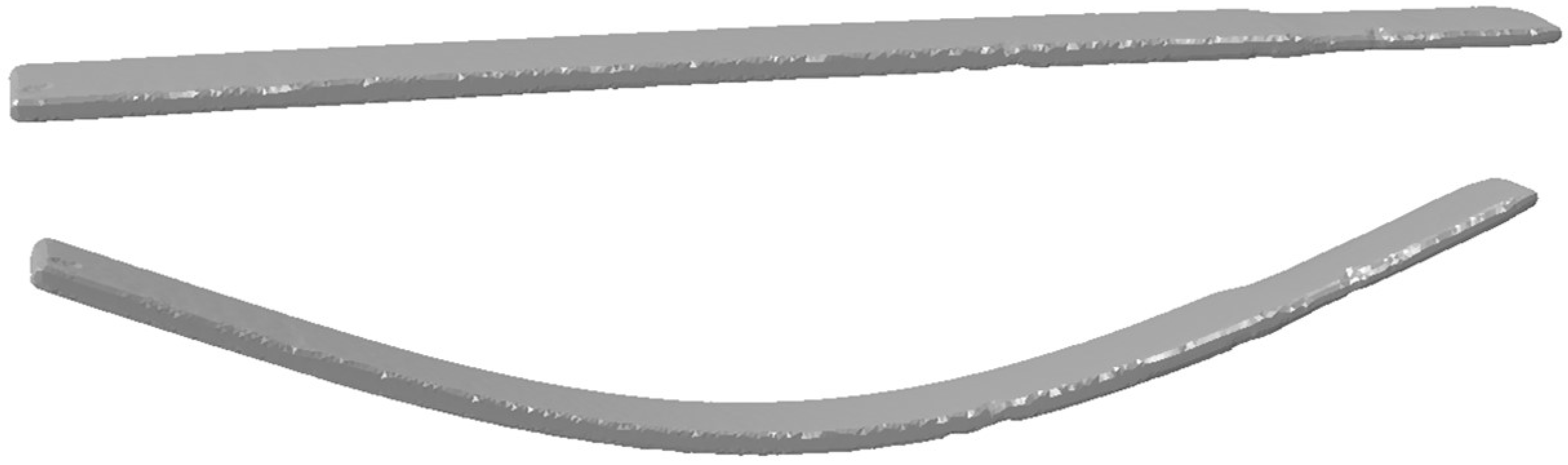
2.1. Casting and Specimen Preparation

Three variations of a Co-15Re-5Cr alloy were investigated in this study: a reference alloy Co-15Re-5Cr, called “Ref”, consisting of a pure solid solution and two alloys with additional C, and Ti (called “TiC”) or Ta (called “TaC”) to form MC-carbides. The compositions of all alloys are given in Table 1. All alloys from Table 1 exhibit, up to 1100 °C, a complete hcp phase [9]. For alloy production, a two-step melting process was performed. A master alloy of Co-20Re was cast in a vacuum induction furnace at VDM Metals International GmbH in Werdohl (Germany), to which the remaining amounts of Co, Re, Cr, Ta, Ti, and C were added by vacuum arc melting in order to achieve the targeted compositions. All alloys received a solution heat treatment in a vacuum atmosphere of 1350 °C/5 h + 1400 °C/5 h + 1450 °C/5 h with subsequent Ar gas quenching. Afterwards, the cast was wire-cut into cylinders with a diameter of 10 mm and a height of 17 mm for creep experiments, as already presented in [13]. Subsequently, an aging heat treatment in vacuum atmosphere at 900 °C/15 h was also performed for all alloys. Although Co-15Re-Cr does not feature a precipitation phase, the aging treatment was also conducted for Co-15Re-5Cr in order to remove residual stresses and adjust the grain size for better comparability with TaC- and TiC-strengthened Co-15Re-5Cr. These samples were used to determine the density with a specific gravity-determination kit, Sartorius 60800 (Sartorius, Göttingen, Germany). Finally, for each alloy, one rectangular plate with a length, thickness, and width of approx. 17 mm, 0.3 mm, and 1.5 mm, respectively, was cut from these cylinders prior to the aforementioned creep tests using a low-speed precision saw to determine Young’s modulus with VR.

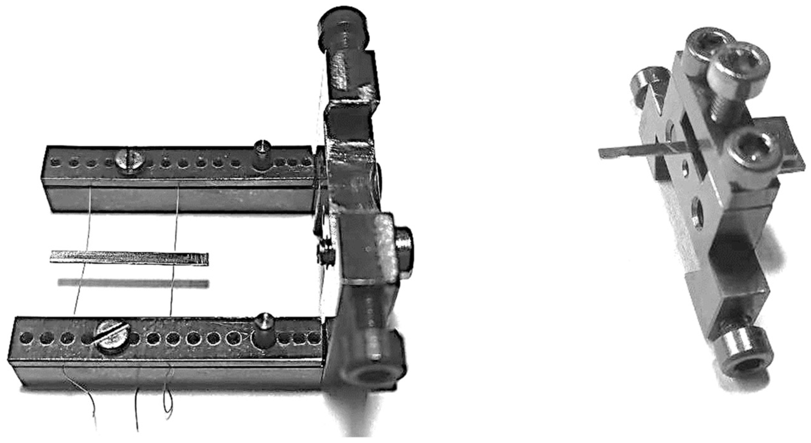
2.2. Experimental Determination of Young’s Modulus with Vibrating Reed

Young’s modulus of the samples was determined using vibrating reed experiments, where resonance frequencies and damping of electrostatically excited flexural vibrations of thin reed-shaped samples are measured. With very small strain amplitudes (typically of the order of 10−6), eigenfrequencies of the vibrating specimen can be detected in a range between 102 s−1 and 2 ∙ 104 s−1. For a detailed description of the vibrating reed apparatus and the measurement method, see [25,26].
The flexural resonance frequencies depend on the dimensions of the specimen, its density, and its stiffness. Thus, by measuring the excited eigenfrequencies fi, the stiffness or Young’s modulus can be calculated. For rectangular parallelepiped-shaped samples with a sufficient length-to-thickness ratio, an analytical solution is available according to classical Euler–Bernoulli beam theory [26,28]:
E = f i 2 · ρ ( 4 π 3 α i 2 · l 2 d ) 2
Hereby, E is Young’s modulus, ρ the density, l the length of the reed, d is its thickness, and αi is the wave number of the i-th vibration mode. Equation (1) may be applied to different boundary conditions called “free-free” and “clamped-free” vibration modes, respectively, where either both ends of the sample are free, or one end is tightly clamped in a stiff mounting device. In the free–free case, the first two modes are given by α1 = 4.730, α2 = 7.853 (higher wave numbers result in a frequency exceeding the upper limit of the measurement apparatus).
However, it was not possible to manufacture ideal rectangular samples from the hard CoReCr-alloys. Small deviations in thickness or a lack of parallelism in the thin samples can have a significant influence on the resonance frequencies. Thus, for accurate measurements, the exact sample geometry can be determined in a computer tomograph. This geometry can then be modeled in FEM, and Young’s modulus of the material can be derived from these simulations (see below). This method is described and validated in detail in [26].
Another crucial point is the experimental realization of the required boundary conditions, which means either an ideally soft suspension of the sample for the free–free vibration or an ideally stiff mounting for the clamped–free vibration, respectively, so that in both cases, the sample vibrations are effectively decoupled from any unwanted instrumental vibrations. This could be best achieved for the free–free vibration mode by placing the flat samples loosely on two very thin (50 µm) copper wires adjusted to the vibration nodes (Figure 1 left). Unfortunately, this setup does not allow reliable measurements at elevated temperatures due to lack of both mechanical stability of the loose samples and a good position for a thermocouple for precise temperature measurement under the required vacuum conditions. Therefore, the free–free vibration mode, preferable for Young’s modulus calculation from the viewpoint of boundary conditions, was only used for measurements at room temperature.
In the case of the clamped–free vibration (Figure 1 right), the thermocouple is directly attached to the clamped side of the vibrating reed and thus delivers more reliable temperature data. Therefore, for measurements in the temperature range of 20 °C to approx. 630 °C (with a heating rate of 2 K/min), the clamped–free configuration was chosen. On the other hand, in this case, the respective boundary condition of “ideally stiff mounting” is more difficult to achieve due to existing experimental limitations of both sample preparation and VR measurement setup. As one consequence, the determination of the effective free length of the clamped vibrating reed (around 10 mm to 12 mm for the present samples), contributing to Equation (1) for Young’s modulus by the power of 4, becomes less precise.
This discussion shows that Young’s modulus at room temperature can reliably be determined on free–free vibrating samples. From temperature-dependent measurements on clamped–free samples, the temperature-dependent change of frequency f(T) was used to determine the temperature dependency of the Young’s modulus, calibrated by the absolute values based on the measurements at room temperature. Here, the temperature dependency of the geometry-based parameters, namely, the density and the length or the free length from Equation (1), was not considered due to its insignificant influence in the investigated temperature range. Estimations of this influence by an approach provided in [23] yield a difference of less than 0.8 % up to a temperature of 600 °C, assuming that the thermal expansion of Co-15Re-5Cr is comparable to that of pure Co.
Prior to the measurements, the mounted samples were heated up to approx. 630 °C and cooled down to room temperature with heating and cooling rates equal to the vibrating reed measurements. The reason for this heat treatment was an irreversible aging effect, where Young’s modulus of the aged MC-containing samples was up to 10 GPa higher than without that heat treatment. The reason for this irreversible aging effect could not be found in this work and could be elucidated in further studies. The irreversibility of the aging effect was checked by two and three vibrating reed measurements across the aforementioned temperature range for Ref and TaC, respectively, whereas for TiC, the temperature-dependent vibrating reed measurement was only conducted once after the aging effect had occurred. A subsequent clamped–free measurement at RT confirmed the permanence of the aging effect. Considering the observations for TaC, no further changes for TiC were expected, and, therefore, no more temperature-dependent measurements were necessary. Hence, in the case of TiC, there is only one temperature-dependent curve displayed in Section 3.2.
For the FEM-assisted determination of Young’s modulus from the eigenfrequencies, the sample geometry was measured in a phoenix nanotom s (General Electric, Lewistown, ME, USA) computer tomograph. The geometry was exported via the STL interface, remeshed with the software TetGen (https://wias-berlin.de/software/index.jsp?id=TetGen&lang=1, Berlin, Germany), and imported in Abaqus Standard. FEM simulations were performed with quadratic, tetrahedral elements with an edge length of about 45 µm to 80 µm, resulting in a total number of approximately 450,000 elements in the model. A mesh convergence study was performed previously to prove that this mesh size is sufficient [26]. Figure 2 exemplarily shows the FEM geometry of a sample in a free–free vibration setup. A typical FEM mesh is shown in detail in Figure 3. The FEM model of the clamped–free sample was fixed with a displacement boundary condition on the clamped end. No boundary conditions were used for the free–free vibrating sample. The densities used in the material model for Ref, TaC and TiC were 11.33 g/cm3, 11.43 g/cm3 and 11.42 g/cm3, respectively. For Young’s modulus, an initial value of 255 GPa was chosen for the simulations. With a linear perturbation step, the eigenfrequencies of the sample with that initial value for Young’s modulus were determined. The real value for Young’s modulus was then determined from the measured frequency, the modeled frequency, and the initial value of Young’s modulus. A repetition of the simulation with this real value for Young’s modulus revealed a modeled frequency equal to the measured frequency and proved the reliability of the determination procedure.

3. Results

3.1. Experimental Determination of Young’s Modulus with Vibrating Reed

Table 2 shows the measured frequency from vibrating reed experiments, the measured density, and FEM-assisted determined Young’s modulus of the three alloys at room temperature. Young’s modulus of the reference alloy without carbides is 233 GPa. The results show that addition of carbides leads to higher stiffness: with TaC, the alloy reaches a Young’s modulus of 242 GPa, and TiC leads to values of 252 GPa.

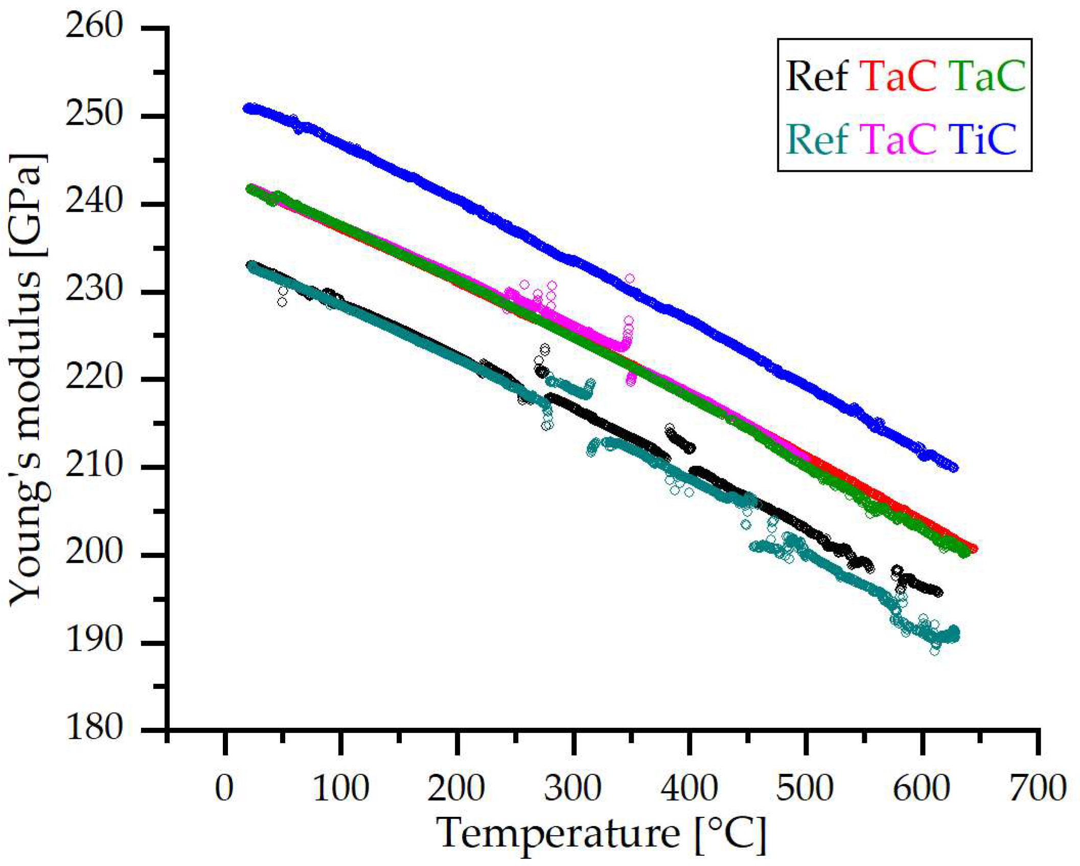
3.2. Temperature Dependency

As explained in the experimental section, temperature-dependent measurements do not allow for an accurate determination of the absolute value of Young’s modulus. However, the temperature-dependent frequency f(T) can be obtained from those measurements. From f(T), the temperature-dependent Young’s modulus can be derived using the already measured Young’s modulus at room temperature (see above). Figure 4 shows the temperature-dependent Young’s modulus of the three tested alloys. It can be seen that Young’s modulus decreases nearly linearly with increasing temperatures, apart from a few jumps and perturbations, which will be assessed in detail in the Discussion in Section 4.2.

4. Discussion

4.1. Influence of Carbides on Young’s Modulus

The results show that the carbide-free CoReCr-alloy investigated in this work has a Young’s modulus significantly higher than that of pure Co (208 GPa), as already estimated in the Introduction in Section 1. Its increase by about 12 % is mostly attributed to the Re content of 15 %. The result is important as CoRe-based alloys are intended for high-temperature applications, and it is well known that the creep strength scales with the elastic stiffness of a metallic material [29,30,31]. Thus, the alloying of Co with Re is not only beneficial since Re raises the melting temperature and causes solid-solution strengthening [13], but it also contributes to the creep strength by elevating the elastic stiffness. Due to the correlation between the strain rate ε ˙ and stress σ of the form ε ˙ ~ σ / E n (n: stress exponent), the latter effect alone is responsible for a creep strength increase of 12 % at a given strain rate.
With the addition of carbides, the resulting Young’s modulus of the particle-containing alloys increases even further. This implies a further increase in creep strength due to the above-mentioned correlation besides particle hardening. However, although TaC has a higher Young’s modulus than TiC, the CoReCr-TiC-alloy shows a Young’s modulus 10 GPa higher than the one of CoReCr-TaC.
The influence of stiff carbides on the Young’s modulus of the CoReCr-alloy can be estimated analytically by the Hashin–Strikman approach (see the Introduction in Section 1): for the effective Young’s modulus of multiphase materials with arbitrary phase geometry and irregularly arranged particles, upper and lower bounds can be calculated for the bulk modulus K and shear modulus G. For the lower bounds, the equations are as follows [22]:
K l = K m + φ p 1 K p K m + 3 φ m 3 K m 4 G m
G l = G m + φ p 1 G p G m + 6 K m + 2 G m φ m 5 G m 3 K m + 4 G m
The indices p and m indicate the particle and matrix, and φ is the volume fraction. For the upper bounds, the indices p and m have to be interchanged in Equations (2) and (3). For both phases, the bulk modulus K and shear modulus G can be derived from Young’s modulus E and Poisson’s ratio ν as follows [32]:
K = E 3 1 2 ν
G = E 2 1 + ν
From the resulting bounds of the bulk and shear modulus for the particle-strengthened alloys (Equations (2) and (3)), the bounds for the Young’s modulus can be derived by
E = 9 K G 3 K + G
Young’s modulus E and Poisson’s ratio ν of the CoReCr-matrix and carbides needed for the calculation of the HS bounds are given in Table 3. For Young’s modulus of the carbides, several different values are available in the literature; see [21] for an overview. For, e.g., TaC, values from 537 GPa to 567 GPa were reported. Regardless, the different values for E lead to a deviation of the calculated values for the effective Young’s modulus of the particle-strengthened materials by less than 0.5 % for volume fractions ≤0.05. Assuming that all Ta, Ti, and C are precipitated from the solid solution, the volume fraction can be calculated using the lattice parameters (see Table 4).
With the given equations and the data in Table 3 and Table 4, the HS bounds for Young’s modulus are as follows:
For TiC-reinforced alloy: 238.1 GPa < E < 238.6 GPa.
For TaC-reinforced alloy: 240.4 GPa < E < 241.9 GPa.
Compared to the measurements, Young’s modulus of the TaC-reinforced alloy (determined value of 242 GPa) matches well with the estimated value of about 240 GPa to 242 GPa. However, for the TiC-reinforced alloy, Young’s modulus of 252 GPa was determined, exceeding the estimated value by 14 GPa. There could be different reasons for this deviation. Besides measurement errors or deviations in chemical composition (especially Re content), the orientation and alignment of the particles could play a significant role. Previous research has shown that the morphology of TiC and TaC is elongated and often aligned in a preferred direction. Thus, the estimation by HS bounds, assuming irregularly arranged particles, could become inaccurate. The comparison of the experimental and calculated results suggests that the elastic stiffness may further increase when the particles align with each other. Note, however, that the particle orientation relative to an external load is still random.

4.2. Temperature Dependency of Young’s Modulus

In part of the curves of the temperature-dependent Young’s modulus shown in Figure 4, a few jumps and other perturbations can be seen, accompanied by some bursts or spikes in damping (not shown in Figure 4), which exceed the generally low damping level of the sample itself. This indicates some transmission of vibration into the measurement apparatus, i.e., some residual coupling with possible instrumental resonances or friction processes due to imperfectly stiff clamping (see above). Such perturbations might be reduced further by making clamped samples softer (longer and/or thinner) in forthcoming studies.
Apart from these perturbations, Young’s modulus decreases nearly linearly with increasing temperature. This is a usual behavior of metals without phase reactions in the relevant temperature range: The approximately linear thermal expansion leads to a stretching of the atomic bonds. This reduces the attracting forces between the atoms and, thus, the stiffness of the bonds is reduced, resulting in a decreasing Young’s modulus. The negative slope of the curves increases with increasing temperatures from −0.06 GPa/K to −0.07 GPa/K. This divergence from the linear trend is not unusual for metals and alloys. Significant influences of microstructural changes can be excluded here: investigations by Karge [12] show that, in the relevant temperature range up to 650 °C, no further precipitation or particle growth will happen. Particle growth after solution heat treatment and quenching takes place at 900 °C but saturates after 15 h. Other microstructural changes such as recrystallization or phase transition from hcp to fcc are not expected to happen, either. The temperature during the vibrating-reed experiments maxed out at approx. 50 % of the melting temperature and approx. 600 °C below the phase-transition temperature of Co-15Re-5Cr for a very short amount of time. After aging at 900 °C for 15h, the alloys were not quenched, but rather cooled down at a quite slow “ambient pace” within the vacuum chamber. Thus, the dislocation density is assumed to be moderate, so that recrystallization is even more unlikely within the temperature and time frame of thermal cycling.
To compare the temperature dependency to that of other metals, the slope of the curves can be normalized to obtain a comparable temperature dependency of
d E d T E ( R T ) T m
with the room-temperature Young’s modulus E(RT) and the melting temperature Tm. Assuming a melting temperature for the CoReCr-alloy of Tm = 1833 K [13], the temperature dependency is −0.47 to −0.55. For comparison, the temperature dependency of Young’s modulus for hcp cobalt is −0.69 (above the hcp/fcc transition temperature, the temperature dependency is stronger) [14]. For Re, it is −0.9 below 200 °C, slightly increasing with higher temperatures up to a value of −0.7 at about 600 °C (derived from [16]). The low temperature dependency of the CoReCr-alloys compared to pure Co underlines the benefit of Re addition to Co (see the Discussion in Section 4.1): the creep strength scales with Young’s modulus. A lower temperature dependency of Young’s modulus results in a higher Young’s modulus of Re-containing alloys at elevated temperatures and thus higher creep strength.

5. Conclusions

The temperature-dependent Young’s modulus of CoRe-based alloys was precisely determined for the first time. This is particularly relevant for future work, whenever strengthening mechanisms are assessed in this alloy class, whereby Young’s modulus is an important input parameter. Specifically, the single-phase alloy Co-15Re-5Cr as well as its MC carbide-containing variants Co-15Re-5Cr-1.8Ta-1.8C and Co-15Re-5Cr-1.8Ti-1.8C were investigated. The main conclusions can be summarized as follows:
  • Young’s modulus of Co-15Re-5Cr is approx. 12 % higher than that of pure Co;
  • Low amounts of TaC and TiC result in a further increase in stiffness;
  • The temperature dependency of Young’s modulus is weaker compared to pure Co;
  • The temperature dependency of Young’s modulus for MC-free and MC-containing Co-15Re-5Cr is similar, so the CoReCr-matrix is mainly responsible for temperature dependency;
  • Analytical estimations of Young’s modulus using the HS bounds are in good agreement with the experimental results obtained for the TaC-containing alloy but inaccurate for the TiC-containing variant.

Author Contributions

Conceptualization, E.S., T.F. and J.R.; methodology, H.-R.S. and E.S.; software, T.F.; investigation, E.S.; writing—original draft preparation, T.F. and E.S.; writing—review and editing, T.F., E.S., H.-R.S. and J.R.; supervision, J.R.; project administration, J.R.; funding acquisition, J.R. All authors have read and agreed to the published version of the manuscript.

Funding

This research was funded by the German Research Foundation-Deutsche Forschungsgemeinschaft (DFG) under grant number 423515565.

Data Availability Statement

Supporting data are available upon request from the corresponding author. The data are not publicly available due to privacy issues.

Acknowledgments

We thank VDM Metals International GmbH for providing the master alloys. Furthermore, we would like to thank Martin Bäker for their support in FEM modeling and Fabian Graef for his computer tomography measurements (the Institute for Materials Science, Technische Universität Braunschweig), as well as Martina Zühlke (Institute of Building Materials, Concrete Construction and Fire Safety, Technische Universität Braunschweig) for her support with the density measurements.

Conflicts of Interest

The authors declare no conflicts of interest.

References

  1. Perepezko, J.H. The hotter the engine, the better. Science 2009, 326, 1068–1069. [Google Scholar] [CrossRef] [PubMed]
  2. Lemberg, J.A.; Ritchie, R.O. Mo-Si-B Alloys for Ultrahigh-Temperature Structural Applications. Adv. Mater. 2021, 23, 3445–3480. [Google Scholar] [CrossRef] [PubMed]
  3. Gombola, C.; Schliephake, D.; Heilmaier, M.; Perepezko, J.H. Creep of an oxidation resistant coated Mo-9Si-8B alloy. Intermetallics 2020, 120, 106743. [Google Scholar] [CrossRef]
  4. Liang, Z.; Paul, J.D.H.; Stark, A.; Bezold, A.; Neumeier, S.; Göken, M.; Pyczak, F. High-Temperature CoNi-Based Superalloys Strengthened by γ′-(Ni,Co)3(Cr,Al,Ti,X): The Effect of Refractory Elements. Metall. Mater. Trans. A 2023, 54A, 1620–1634. [Google Scholar] [CrossRef]
  5. Makineni, S.K.; Sharma, A.; Pandey, P.; Chattopadhyay, K. An Overview on Co-Base Alloys for High Temperature Applications. Encycl. Mater. Met. Alloys 2020, 1, 323–334. [Google Scholar] [CrossRef]
  6. Sato, J.; Omori, T.; Oikawa, K.; Ohnuma, I.; Kainuma, R.; Ishida, K. Cobalt-Base High-Temperature Alloys. Science 2006, 312, 90–91. [Google Scholar] [CrossRef] [PubMed]
  7. Rösler, J.; Mukherji, D.; Baranski, T. Co-Re-based Alloys: A New Class of High Temperature Materials? Adv. Eng. Mater. 2007, 9, 876–881. [Google Scholar] [CrossRef]
  8. Massalski, T.B.; Okamoto, H.; Subramanian, P.R.; Kacprzak, L. Binary Alloy Phase Diagrams; ASM International: Materials Park, OH, USA, 1990. [Google Scholar]
  9. Seif, E.; Rösler, J. Reassessment of the Matrix Composition of Co-Re-Cr-Based Alloys for Particle Strengthening in High-Temperature Applications and Investigation of Suitable MC-Carbides. Materials 2023, 16, 4443. [Google Scholar] [CrossRef]
  10. Depka, T.; Somsen, C.; Eggeler, G.; Mukherji, D.; Rösler, J. Sigma phase evolution in Co–Re–Cr-based alloys at 1100 °C. Intermetallics 2014, 48, 54–61. [Google Scholar] [CrossRef]
  11. Wanderka, N.; Mousa, M.S.; Henke, P.; Korchuganova, O.; Mukherji, D.; Rösler, J.; Banhart, J. Carbides in Co–Re–Cr-based high-temperature alloys. J. Mater. Sci. 2016, 51, 7145–7155. [Google Scholar] [CrossRef]
  12. Karge, L.; Gilles, R.; Mukherji, D.; Strunz, P.; Beran, P.; Hofmann, M.; Gavilano, J.; Keiderling, U.; Dolotko, O.; Kriele, A.; et al. The influence of C/Ta ratio on TaC precipitates in Co-Re base alloys investigated by small-angle neutron scattering. Acta Mater. 2017, 132, 354–366. [Google Scholar] [CrossRef]
  13. Seif, E.; Rösler, J.; Werner, J.; Weirich, T.E.; Mayer, J. Investigation of TaC and TiC for Particle Strengthening of Co-Re-Based Alloys. Materials 2023, 16, 7297. [Google Scholar] [CrossRef]
  14. Selle, J.E. Innere Reibung von Kobalt (Internal friction in cobalt). Kobalt 1969, 45, 163–166. [Google Scholar]
  15. Sargent, P.M.; Ashby, M.F.; Malakondaiah, G. A Deformation Map for Cobalt. Scr. Metall. 1983, 17, 625–629. [Google Scholar] [CrossRef]
  16. Sims, C.T.; Jaffee, R.I. Further Studies of the Properties of Rhenium Metal. J. Met. 1956, 8, 913–917. [Google Scholar] [CrossRef]
  17. Karge, L.; Gilles, R.; Mukherji, D.; Beran, P.; Strunz, P.; Hoelzel, M.; Rösler, J. Beyond Ni-base superalloys: Influence of Cr addition on Co-Re base alloys strengthened by nano-sized TaC precipitates. Phys. B 2018, 551, 1–5. [Google Scholar] [CrossRef]
  18. Wang, L.; Gorr, B.; Christ, H.-J.; Mukherji, D.; Rösler, J. Microstructure and Oxidation Mechanism Evolution of Co–17Re–25Cr–2Si in the Temperature Range 800–1100 °C. Oxid. Met. 2015, 83, 465–483. [Google Scholar] [CrossRef]
  19. Sims, C.T. High-Temperature Materials for Aerospace and Industrial Power; Wiley: New York, NY, USA, 1987. [Google Scholar]
  20. Hocker, S.; Lipp, H.; Schmauder, S.; Bakulin, A.V.; Kulkova, S.E. Ab initio investigation of Co/TaC interfaces. J. Alloys Compd. 2021, 853, 156944. [Google Scholar] [CrossRef]
  21. Dodd, S.P.; Cankurtaran, M.; James, B. Ultrasonic determination of the elastic and nonlinear acoustic properties of transition-metal carbide ceramics: TiC and TaC. J. Mater. Sci. 2003, 38, 1107–1115. [Google Scholar] [CrossRef]
  22. Hashin, Z.; Shtrikman, S. A Variational Approach to the Theory of the Elastic Behaviour of Multiphase Materials. J. Mech. Phys. Solids 1963, 11, 127–140. [Google Scholar] [CrossRef]
  23. Hill, W.H.; Shimmin, K.D. Elevated Temperature Dynamic Elastic Moduli of Various Metallic Materials. 1961, US Air Force WADD Technical Report 60-438. Available online: https://www.osti.gov/biblio/4806475 (accessed on 8 November 2023).
  24. Whiting, R.; Jacobsen, P.H. An evaluation of the vibrating reed method for determining the mechanical properties of materials. J. Biomed. Eng. 1983, 5, 31–36. [Google Scholar] [CrossRef] [PubMed]
  25. Yamaguchi, M.; Bernhardt, J.; Faerstein, K.; Shtansky, D.; Bando, Y.; Golovin, I.S.; Sinning, H.-R.; Golberg, D. Fabrication and characteristics of melt-spun Al ribbons reinforced with nano/micro-BN phases. Acta Mater. 2013, 61, 7604–7615. [Google Scholar] [CrossRef]
  26. Rösemann, N.; Fiedler, T.; Sinning, H.-R.; Bäker, M. Determining Young’s modulus of coatings in vibrating reed experiments using irregularly shaped specimens. Results Mater. 2019, 2, 100022. [Google Scholar] [CrossRef]
  27. Fiedler, T.; Sinning, H.-R.; Rösler, J.; Bäker, M. Temperature dependent mechanical properties of metallic HVOF coatings. Surf. Coat. Technol. 2018, 349, 32–36. [Google Scholar] [CrossRef]
  28. Han, S.M.; Benaroya, H.; Wei, T. Dynamics of Transversely Vibrating Beams using four Engineering Theories. J. Sound Vib. 1999, 225, 935–988. [Google Scholar] [CrossRef]
  29. Mukherji, A.K.; Bird, J.E.; Dorn, J.E. Experimental Correlations for High-Temperature Creep. Trans. ASM 1969, 62, 155–179. [Google Scholar]
  30. Sherby, O.D.; Miller, A.K. Combining Phenomenology and Physics in Describing the High Temperature Mechanical Behavior or Crystalline Solids. J. Eng. Mater. Technol. 1979, 101, 387–395. [Google Scholar] [CrossRef]
  31. Blum, W.; Eisenlohr, P.; Breutinger, F. Understanding Creep—A Review. Metall. Mater. Trans. A 2002, 33A, 291–303. [Google Scholar] [CrossRef]
  32. Rösler, J.; Harders, H.; Bäker, M. Mechanisches Verhalten der Werkstoffe (Mechanical Behaviour of Materials); Springer: Berlin/Heidelberg, Germany, 2019; ISBN 978-3-658-26801-5. [Google Scholar]
  33. Köster, W. Poisson’s ratio for metals. Appl. Sci. Res. 1954, 4, 329–336. [Google Scholar] [CrossRef]
  34. Beran, P.; Mukherji, D.; Strunz, P.; Gilles, R.; Hofmann, M.; Karge, L.; Dolotko, O.; Rösler, J. Effect of Composition on the Matrix Transformation of the Co-Re-Cr-Ta-C Alloys. Met. Mater. Int. 2016, 22, 562–571. [Google Scholar] [CrossRef]
  35. Li, Y.; Wang, W.; Zhu, B.; Xu, M.; Zhu, J.; Hao, Y.; Li, W.; Long, X. Elastic and thermodynamic properties of TiC from first-principles calculations. Sci. China Phys. Mech. Astron. 2011, 54, 2196–2201. [Google Scholar] [CrossRef]
Figure 1. Sample mounts for vibrating reed experiments. (Left) free–free vibration where the sample is loosely placed on thin wires. (Right) clamped–free vibration where the sample is fixed on one side in a stiff mount.
Metals 14 00324 g001
Figure 2. FEM model of a vibrating reed sample in free–free vibration setup: initial geometry (top) and exaggerated deformation of first-order vibration mode (bottom).
Metals 14 00324 g002
Figure 3. Detail of FEM mesh.
Metals 14 00324 g003
Figure 4. Temperature-dependent Young’s modulus of the three alloys.
Metals 14 00324 g004
Table 1. Compositions of the alloys investigated in this study in at.%.
AlloyCoReCrTaTiC
RefBal.155---
TaCBal.1551.8-1.8
TiCBal.155-1.81.8
Table 2. Measurement data of the free–free vibration mode and Young’s modulus derived from FEM analysis at room temperature.
AlloyFrequency [1/s]Density [g/cm3]Young’s Modulus [GPa]
Ref502211.33233
TaC456911.43242
TiC500211.42252
Table 3. Young’s modulus and Poisson’s ratio of CoReCr-matrix and carbides used for calculation of HS bounds.
CoReCr-MatrixTiCTaC
E [GPa]233.4 (this work)436 [21]567 [21]
ν [-]0.32 [33]0.215 [21]0.187 [21]
Table 4. Lattice parameters of CoRe-matrix and carbides as well as calculated volume fractions (assuming that 1.8 at.% Ta or Ti, respectively, have completely formed carbides).
AlloyLattice Parameters [nm]Calculated Volume Fraction of Carbides
a Matrixc Matrixa Carbides
TiC0.2552 [34]0.4121 [34]0.433 [35]0.032
TaC0.2552 [34]0.4121 [34]0.4444 [12]0.034
Disclaimer/Publisher’s Note: The statements, opinions and data contained in all publications are solely those of the individual author(s) and contributor(s) and not of MDPI and/or the editor(s). MDPI and/or the editor(s) disclaim responsibility for any injury to people or property resulting from any ideas, methods, instructions or products referred to in the content.

