Article

Laser Remelting of Ductile Cast Iron to Achieve a Graphite-Free Surface Layer for Enabling a Manual High-Gloss Finish

by
Laura Kreinest
1,*,
Johannes Schüssler
2,
Onur Özaydin
2,
Sujith Kochuthundil Subhash
2,
Edgar Willenborg
1 and
Andreas Bührig-Polaczek
2
1
Fraunhofer Institute for Laser Technology, Steinbachstraße 15, 52074 Aachen, Germany
2
Foundry Institute of RWTH Aachen, Intzestraße 5, 52072 Aachen, Germany
*
Author to whom correspondence should be addressed.
Metals 2024, 14(3), 347; https://doi.org/10.3390/met14030347
Submission received: 14 February 2024 / Revised: 4 March 2024 / Accepted: 12 March 2024 / Published: 18 March 2024
(This article belongs to the Topic Laser Processing of Metallic Materials)

Abstract

:
Laser remelting is being explored as a viable technique for obtaining a graphite-free, defect-free surface layer on cast iron EN GJS 400-15. The goal is to obtain a large remelted layer along with a low surface roughness to enable a subsequent manual high-gloss surface finish. The impact of the laser remelting process parameters is evaluated by using samples with three different cooling rates, resulting in different graphite microstructures. By utilizing four passes and a laser power of 300 W, the smallest roughness and largest remelting depth are achieved. The remelted layer is mostly devoid of graphite particles. Subsequent manual polishing is performed to evaluate the potential for achieving a high-gloss finish with a roughness of Sa < 0.05 µm. Laser remelting alone does not improve visual appearance or reduce roughness. However, after manual polishing, the roughness of the laser-remelted surfaces with Sa = 0.018 µm is one order of magnitude smaller than the manually polished initial state. Graphite removal during laser remelting therefore makes it possible to achieve a conventional and high-gloss polish, overcoming the previous limitations of GJS materials.

1. Introduction

Molding tools for mass production must be manufactured according to application-dependent requirements in terms of geometry and surface finish, while also exhibiting minimal wear to maintain product quality across multiple molding processes [1,2,3]. Several variants of spheroidal graphite cast iron (GJS) fulfill these requirements for applications such as the deep-drawing of sheet metal parts and blowing or pressing glasses [4]. In other domains, like metal die-casting and plastic injection-molding, the material’s high thermal conductivity and cost-effective production make it inherently suitable [5,6]. However, the utilization of this material has been hindered by its inadequate surface qualities, primarily attributed to the exposure of enclosed graphite particles during conventional manual polishing. Furthermore, the comparatively lower hardness of cast iron, in contrast to the hardened tool steels commonly employed, results in expedited tool wear [5].
An approach to increase the hardness of GJS is laser heat treatment [7,8] or laser remelting [5,9,10,11,12,13]. The laser remelting of metals involves the remelting of a thin surface layer, typically ranging from 1 to 100 µm, using laser radiation. In the molten phase, the surface is smoothed by the surface tension and solidifies in the smoothed state [14].
While laser remelting has been studied extensively for materials like tool steels, stainless steels, titanium and nickel-based alloys in more than 60 publications [15,16,17], only a handful of studies have focused on the laser remelting of cast iron to improve the polishability of cast iron by removing graphite from the surface. Kiedrowski et al. [18] and Ukar et al. [19,20,21] explored the laser remelting of EN-GJS-700-2 [22] and were able to reduce the quantity and size of graphite particles in the remelted surface layer by using CO2 as a shielding gas atmosphere. Following laser remelting, a roughness of Ra = 0.5 µm and a hardened layer with a remelting depth of d = 350 µm were achieved [20,21,23]. Benyounis et al. [23] also found that the laser remelting of spheroidal cast iron dissolves most of the graphite particles. They obtained a remelted layer with a remelting depth of d = 500 µm which includes retained austenite, martensite and cementite. Pagano et al. [24] also demonstrated that laser remelting results in a reduction in graphite content within the remelting zone while obtaining a remelted layer containing austenite.
The primary objective of this study is to adapt the process parameters, specifically the laser power and number of passes, for the laser remelting of cast iron in order to achieve a defect-free surface layer devoid of graphite. In this context, defect-free means that there are no visible graphite particles on the surface of the remelted sample. Samples made from three different geometries with varying cooling rates resulting in different graphite microstructures are employed to investigate the impact of the laser remelting process parameters. Upon achieving a graphite-free surface through laser remelting, a remelting depth > 50 µm and a low surface roughness are desirable as they allow for subsequent manual polishing to improve surface roughness by removing material.

2. Materials and Methods

2.1. Materials

The laser remelting experiments were conducted on spheroidal graphite cast iron EN-GJS-400-15 [22] samples. The chemical composition of the material is provided in Table 1.
Three distinct geometries (YII, YIV and a cylinder), as illustrated in Figure 1a, were produced through a single casting process, each exhibiting distinct cooling rates. In the laboratory-scale casting of ductile cast iron, raw materials are melted in a controlled induction furnace. After magnesium treatment and inoculation, the molten metal is cast into a sand mold and left to cool to room temperature. The cooling curves of the three geometries are depicted in Figure 1b. The YII geometry displays a higher cooling rate in contrast to the YIV geometry, whereas the cylinder geometry exhibits the lowest cooling rate among the three geometries.
Figure 2 shows microscopic images of metallographically prepared cross-sections from the three geometries. Graphite content, nodularity and nodule count are determined to describe and analyze the graphite microstructure [25]. The graphite content is the amount of graphite in the iron matrix. The graphite content is determined by converting a microscope image into a black and white image and calculating the ratio of the black to white surface area. Nodularity refers to the proximity of a graphite particle to a circular shape. The nodularity is calculated as the area of graphite particles with specific roundness divided by the total area of all graphite particles. The nodule count represents the total number of graphite particles that qualify as nodules and is calculated as the number of graphite particles per mm2 [26]. Figure 3 presents the determined results of the graphite content, nodularity and nodule count for each of the geometries based on five images. In Figure 3a, the graphite content of the three geometries is depicted. The microstructure of the cylinder geometry exhibits the highest graphite content of 11.2%, while the YIV and YII geometries exhibit a graphite content ranging from 9% to 10%. The nodularity for all three geometries is relatively consistent, ranging from 65% to 75% (refer to Figure 3b), with the cylinder geometry demonstrating the lowest nodularity. The microstructures of the three geometries differ primarily in their nodule count, as depicted in Figure 3c. The nodule count displayed by the YII geometry is up to twice as high as that of the other two geometries. An increase in graphite content is often associated with a decrease in nodularity [25], while higher cooling rates result in higher nodule counts [27].
Test samples for laser polishing and remelting were created by cutting cast iron parts into 10 mm thick plates. Subsequently, the plates were milled to attain a flat and parallel surface with a roughness of Sa = 0.51 µm. Prior to laser remelting, the plates were cleaned using ethanol.

2.2. Laser Remelting Process and Machine

Laser remelting utilizing continuous laser radiation is capable of smoothing structural components with a structural wavelength up to twice the laser beam diameter. In laser remelting with pulsed laser radiation, mainly structural components with structural wavelengths of λ < 40 µm are smoothed [28]. Since in laser remelting with pulsed laser radiation the remelting depth of <5 μm [14] is smaller than the size of the graphite nodules, laser remelting with continuous wave laser radiation is preferred for GJS.
The laser remelting experiments within this work were carried out with the experimental set-up shown in Figure 4. The fiber laser used in this system is a redPOWER (SPI Laser Ltd., Southampton, UK) emitting continuous wave laser radiation with a wavelength of λem = 1075 nm–1080 nm with a maximum laser power of PL,max = 500 W. The laser radiation emitted from the laser beam source is coupled with the optical setup via a fiber-optic cable with a core diameter of Ø = 300 µm and a numerical aperture of NA = 0.1. Using a collimating lens with a focal length of 114 mm, an f theta lens with a focal length of 163 mm and a zoom telescope, the laser beam diameter in the focal plane can be continuously adjusted in the range of dL = 120–625 µm. With a galvanometric laser scanner (hurrySCAN30, Scanlab GmbH, Puchheim, Germany), the focused laser beam can be moved over the workpiece surface.
For the experiments, a focused laser beam with a circular laser beam diameter of dL = 500 µm was guided in a meandering pattern over the surface at a scanning speed vscan = 50 mm/s. A track distance with dy = 100 µm between parallel adjacent tracks was selected, which was smaller than the laser beam diameter for the processing of a test field with overlapping tracks. Further process parameters included the number of passes n and the processing direction α, i.e., the direction of the scan vectors in relation to the direction of the dominant structures on the initial surface of the workpiece (e.g., milling grooves). The first pass was perpendicular to the dominant structures (α = 90°). For further passes, the processing direction was rotated by 90° to the previous pass. CO2 was used as a shielding gas atmosphere to reduce the graphite content in the surface layer during laser processing [18,19,20,21]. The residual oxygen content in the shielding gas was maintained at 700–1000 ppm during the process.

2.3. Analysis

The surface topography was measured with a Nexview NX2 (Zygo Corporations, Middlefield, CT, USA) using white-light interferometry (WLI). The resolution of the surface topography measurements (5.5× magnification and 0.5× zoom) was 3.14 μm in the lateral direction and <1 nm in the vertical direction. The roughness Sa was determined from the measured surface topography after DIN EN ISO 4288 [29] and DIN EN ISO 25178 [30] as the mean arithmetic height of a fixed area of 2.5 × 2.5 mm2. For this purpose, a high-pass filter of λ = 0.8 mm was applied. The roughness was determined for each test field at three different positions.
The remelting depth was measured at five locations, as shown in the example given in Figure 5, from a microscopic image of the etched metallographically prepared cross-section of each laser-remelted test field.
The metallographically prepared cross-sections were analyzed with an Axio Scope A1 light microscope (Carl Zeiss AG, Oberkochen, Germany), and the selected cross-sections with a scanning electron microscope and electron backscatter diffraction (EBSD) with a Supra 55VP (Carl Zeiss AG).

3. Results

3.1. Comparison of the Graphite Microstructures
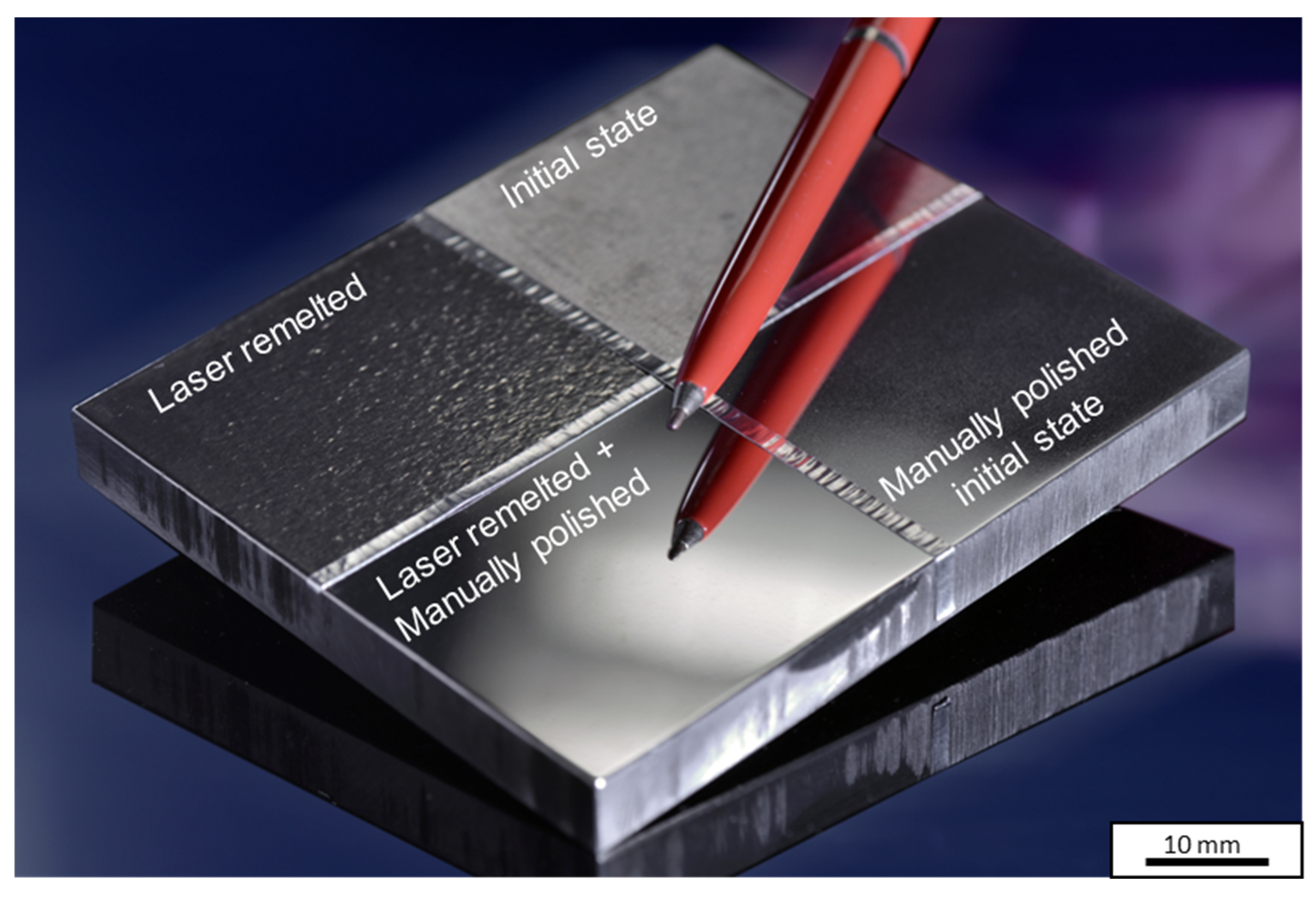
In order to facilitate manual high-gloss finishing, it is crucial to minimize the roughness and roughness peaks after laser remelting. Consequently, the initial investigation focused on examining the influence of laser power and the number of passes on the surface roughness. According to Kiedrowski [31], it is expected that the roughness will initially decrease with increasing laser power or an increasing number of exposures, as the initial surface is increasingly smoothed. Therefore, the laser power was varied in four steps (PL = 150 W, 200 W, 250 W and 300 W) and the number of passes in two steps (n = 1 and n = 4). Figure 6 shows the surface roughness of the laser-polished test fields as a function of laser power for the three investigated microstructures. Figure 6a shows the surface roughness for a single pass and Figure 6b for four passes.
For one pass (Figure 6a), the roughness increases with increasing laser power for all microstructures investigated. While the roughness at a laser power of PL = 150 W is in the range of Sa = 0.55 µm (geometry YII) to Sa = 0.87 µm (cylinder geometry), it increases at a laser power of PL = 300 W to Sa = 1.58 µm (geometry YII) and Sa = 2.42 µm (cylinder geometry). Geometry YII has a smaller roughness for all examined laser powers. For four passes, a roughness of Sa < 1 µm is determined for all examined microstructures for all laser powers. The smallest roughness is obtained with a laser power of PL = 300 W for geometry YIV with Sa = 0.41 µm, which is similar to the roughness obtained by Ukar et al. [6,7,8].
The underlying cause for the smaller roughness observed after laser remelting with four passes becomes apparent upon examining the microscopic images of the laser-remelted surfaces. Exemplary microscopic images of the laser-remelted test fields, remelting the YIV geometry with a laser power of PL = 300 W, are presented in Figure 7. Specifically, Figure 7a,b depict the surface after a single pass, while Figure 7c,d display the surface after four passes. After a single pass, the remelted surface of the test field shows the presence of defects, which is likely the cause of the high roughness. However, after four passes, the surface is nearly defect-free and exhibits no visible graphite particles, resulting in a reduction in roughness.
The remelting depth’s dependence on laser power and the number of passes is determined in the following. Figure 8 shows the remelting depth as a function of laser power for all three microstructures investigated. Figure 8a shows the remelting depth for one pass and Figure 8b for four passes.
For both one and four passes, the determined remelting depth increases with the laser power and does not differ outside the standard deviation for the three microstructures investigated. For one pass, the remelting depth at PL = 150 W is between d = 28 µm (geometry YIV) and d = 44 µm (geometry YII). For PL = 300 W, the remelting depth increases by a factor of 3–4 to d = 111 µm (geometry YIV) and d = 123 µm (geometry YII and cylinder). For four passes, the remelting depth at PL = 150 W is between d = 37 µm (cylinder geometry) and d = 57 µm (geometry YIV) and therefore slightly higher than the remelting depth determined after one pass. For PL = 300 W, the remelting depth increases by a factor of 2–3 to values between d = 125 µm (geometry YIV) and d = 137 µm (geometry YII). The influence of the number of passes on the remelting depth is thus much smaller than the influence of the laser power.
Figure 9 shows microscopic images of the metallographically prepared cross-sections of the laser-remelted test fields with PL = 300 W on the YIV geometry with one pass (Figure 9a) and four passes (Figure 9b). The remelted surface layer after one pass contains fewer graphite particles than the initial state of the ductile cast iron (cf. Figure 2). The graphite particles are marked yellow in Figure 9a and are located close to the surface. For four passes, the cross-section shows no graphite particles in the remelted surface layer.

3.2. Demonstration

After successfully demonstrating the creation of a graphite-free surface layer through laser melting, the next objective is to identify a set of process parameters that can achieve both minimal roughness and maximum remelting depth. Given that the impact of the three microstructures on the outcome of laser remelting is negligible, the investigations were conducted on the cylinder geometry. This geometry, characterized by the lowest investigated cooling rate, closely emulates industrial casting processes employed in the fabrication of deep-drawing or mold tools.
Figure 10a shows the remelting depth and Figure 10b the roughness as a function of laser power for different numbers of passes on the cylinder geometry. As previously observed, the remelting depth increases with laser power. Doubling the laser power from PL = 150 W to PL = 300 W leads to a melting depth that is, on average, 3.4 times larger. The remelting depth also tends to increase with an increasing number of passes. When the number of passes is increased from n = 1 to n = 8, the average remelting depth increases by a factor of 1.3.
The impact of laser power and the number of passes on roughness is not as evident as on the remelting depth. In the case of a single pass, roughness increases with an increase in laser power from Sa = 0.872 µm (PL = 150 W) to Sa = 2.418 µm (PL = 300 W). This can be attributed to the presence of graphite particles on the surface, as observed in Figure 9a. However, as the number of passes is increased to n = 2 and n = 4, roughness decreases with higher laser power as a graphite-free surface layer is achieved. The minimum roughness of Sa = 0.53 µm is obtained with a laser power of PL = 300 W and four passes. With a further increase in the number of passes to n = 8, the roughness increases as observed for n = 1 with increasing laser power. The underlying cause cannot be attributed to the presence of graphite particles on the surface, but rather, increasing oxidation of the sample surface.
With four passes and a laser power of PL = 300 W, the largest remelting depth and the smallest roughness are achieved. Figure 11a shows a microscopy image of the cross-section and Figure 11b an image of the surface topography of the test field. In addition, a scanning electron microscopy (SEM) image and an electron backscatter diffraction (EBSD) image are shown in Figure 12a,b. In the EBSD image, the microstructure before and after laser remelting can be analyzed.
The SEM image reveals distinct features in different regions: the upper part displays the remelted surface layer, while the lower part shows the initial ferritic structure. The laser remelting process induces a phase transformation in the remelted surface layer, resulting in the formation of an austenitic structure. A thin martensitic layer is observed between the initial ferritic structure and the produced austenitic surface layer. The remelted layer is largely free of graphite particles. However, in the vicinity of the transition zone between the remelted surface layer and the initial structure, an increasing presence of graphite particles is observed. The EBSD picture in Figure 12 shows bcc (body-centered cubic) and fcc (face-centered cubic) phases. The red bcc phases represent the ferrite and the blue fcc phases the austenite.
Based on the EBSD, SEM and light microscopic examination of the cross-sections, it is observed that the remelted surface layer is predominantly devoid of graphite. In order to investigate the feasibility of achieving a high-gloss finish, meaning a roughness of Sa < 0.05 µm, the laser-remelted surface is subjected to manual polishing. The demonstrator shown in Figure 13 was made for this purpose. It consists of a flat sample divided into four quadrants, each with a different surface state. These quadrants consist of the initial state, a laser-remelted surface, the manually polished initial state and a surface that has been subjected to laser remelting followed by manual polishing.
Laser remelting alone does not improve the visual appearance of the initial condition, nor does it reduce the roughness, but instead, increases it from Sa = 0.51 µm to Sa = 0.53 µm. After subsequent manual polishing, the laser-remelted surface has a roughness of Sa = 0.018 µm and therefore a high-gloss finish. The roughness of the manually polished initial state is Sa = 0.103 µm, so a high-gloss finish cannot be achieved.
Figure 14a shows the surface topography of the initial manually polished state, while Figure 14b shows the surface topography of the laser-remelted and subsequently manually polished state. When comparing the surface topographies, it is evident that the surface that underwent laser remelting exhibits considerably fewer defects, thus resulting in less roughness.

4. Discussion

Although ductile cast irons have good thermal conductivity and can be cast to produce complex and large tool geometries, they are often overlooked for other potential tooling applications. There are two main reasons for this. Compared to hot-work tool steels, cast iron alloys have lower wear properties due to their lower material hardness. Additionally, the polishability of the material is limited by the graphite particles in its microstructure.
The objective of the investigations is to produce a steel-like, defect-free surface layer that can be polished to a high-gloss finish. The aim is to enable the industrial use of cast iron for molding tools, which have traditionally been made exclusively from tool steel.
This investigation demonstrated that a surface with no visible graphite particles can be achieved using four passes and a laser power of PL = 300 W. The reason why four passes are necessary is that not all of the graphite can be removed after a single remelting. This is likely due to the interaction time between the melt pool and the CO2 atmosphere being too short for the graphite to dissolve or be removed. CO2 is crucial as a shielding gas to remove graphite from the remelted zone. The surface layer is decarburized through the following mechanism: during the interaction between laser radiation and the material, CO2 dissociates into CO and O2. The carbon from the melt pool combines with oxygen to form CO. The process gas containing oxygen promotes the reformation of CO2 from the carbon monoxide that is formed. The experiments conducted demonstrate that using CO2 as a shielding gas during laser remelting with four passes can achieve a graphite-free surface layer for all investigated graphite microstructures.
It was also found that all three investigated microstructures exhibit similar remelting depth and roughness after laser remelting. The microstructures differ mainly in the nodule count. The laser remelting process is therefore not affected by the different nodule counts that were investigated. This is advantageous for prospective industrial applications as the microstructure, particularly the nodule count, can vary within a manufactured part. This is due to different geometric elements of a part exhibiting varying local cooling rates, such as those caused by differences in wall thickness.
After laser remelting, the remelted layer exhibits an austenitic microstructure. A similar microstructure was also found by Pagano et al. [24], while Benyounis et al. [23] found a microstructure which includes retained austenite, martensite and cementite. Tool steels, such as H12 or H13, usually have a microstructure of martensite with retained austenite [32].
The smallest roughness achieved by laser remelting is Sa = 0.41 µm, which is obtained with a laser power of PL = 300 W and four passes. The roughness is similar to the roughness obtained in the literature [6,7,8]. With subsequent manual polishing, a roughness of Sa = 0.018 µm, and therefore, a high-gloss finish can be achieved on cast iron. The roughness of the manually polished initial state is Sa = 0.103 µm; a high-gloss finish can therefore not be achieved without laser remelting as a pre-treatment.

5. Conclusions

In conclusion, this investigation focused on the laser remelting of ductile cast iron to achieve a graphite-free surface layer with a large remelting depth and a low surface roughness, as this allows for subsequent manual polishing to achieve a high-gloss finish. Samples with three different graphite microstructures were laser-remelted to investigate the impact of laser remelting process parameters. The influence of laser power and the number of passes on surface roughness was examined, revealing that a combination of four passes and a laser power of PL = 300 W achieved the smallest roughness of Sa = 0.41 µm and the largest remelting depth of d = 137 µm. Scanning electron microscopy (SEM) and EBSD analysis revealed the formation of an austenitic structure in the remelted surface layer, with a thin martensitic layer between the initial ferritic structure and the produced austenitic layer. The remelted layer was found to be mostly free of graphite particles and consisted of austenite (fcc iron), which could be identified by EBSD measurements.
To evaluate the potential for achieving a high-gloss finish, which means a roughness of Sa < 0.05 µm, a laser-remelted surface underwent manual polishing. The results indicate that laser remelting alone cannot enhance visual appearance or reduce roughness. However, after subsequent manual polishing, the roughness of the laser-remelted surface was reduced below that of a manually polished surface. Surface topography analysis revealed fewer defects in the form of graphite at the surface and a smoother appearance in the laser-remelted and subsequently manually polished surface, resulting in a high-gloss finish with a roughness of Sa = 0.018 µm. These findings suggest that laser remelting, when followed by manual polishing, can improve the surface quality and may serve as a beneficial pre-treatment step for achieving a high-gloss finish on cast iron.

Author Contributions

Conceptualization, L.K., J.S. and O.Ö.; methodology, L.K., J.S., S.K.S. and E.W.; formal analysis, L.K., J.S., O.Ö. and S.K.S.; investigation, S.K.S., L.K. and J.S.; data curation, L.K., S.K.S. and J.S.; writing—original draft preparation, L.K.; writing—review and editing, E.W., O.Ö., J.S. and A.B.-P.; funding acquisition, E.W. and A.B.-P. All authors have read and agreed to the published version of the manuscript.

Funding

This research was funded by the Federal Ministry for Economic Affairs and Climate Action, grant number 22681.

Data Availability Statement

The data presented in this study are available on request from the corresponding author.

Acknowledgments

The authors would like to thank Bestenlehrer GmbH for the manual polishing of the demonstrator sample.

Conflicts of Interest

The authors declare no conflicts of interest.

References

  1. Bissacco, G.; Hansen, H.N.; de Chiffre, L. Micromilling of hardened tool steel for mould making applications. J. Mater. Process. Technol. 2005, 167, 207–210. [Google Scholar] [CrossRef]
  2. Griffiths, C.A.; Dimov, S.S.; Brousseau, E.B.; Hoyle, R.T. The effects of tool surface quality in micro-injection moulding. J. Mater. Process. Technol. 2007, 189, 418–427. [Google Scholar] [CrossRef]
  3. Kluck, S.; Hambitzer, L.; Luitz, M.; Mader, M.; Sanjaya, M.; Balster, A.; Milich, M.; Greiner, C.; Kotz-Helmer, F.; Rapp, B.E. Replicative manufacturing of metal moulds for low surface roughness polymer replication. Nat. Commun. 2022, 13, 5048. [Google Scholar] [CrossRef] [PubMed]
  4. Fallböhmer, P.; RodrõÂguez, C.A.; Ozel, T.; Altan, T. High-speed machining of cast iron and alloy steels for die and mold manufacturing. J. Mater. Process. Technol. 2000, 98, 104–115. [Google Scholar] [CrossRef]
  5. Catalán, N.; Ramos-Moore, E.; Boccardo, A.; Celentano, D. Surface Laser Treatment of Cast Irons: A Review. Metals 2022, 12, 562. [Google Scholar] [CrossRef]
  6. Yakut, R.; Ortakaya, R. Investigation of the Effect of Additional Zirconium Diboride (ZrB2) in Spherical Graphite Cast Iron on Mechanical Properties. Coatings 2023, 13, 1385. [Google Scholar] [CrossRef]
  7. Lagarinhos, J.N.; Santos, S.; Miranda, G.; Afonso, D.; Torcato, R.; Santos, C.; Oliveira, J.M. The influence of surface finishing on laser heat treatments of a tool steel. Procedia CIRP 2022, 108, 839–844. [Google Scholar] [CrossRef]
  8. Sun, F.; Li, Y.; Tan, W.; Pang, M. Effect of laser scanning speed on the thermal-mechanical coupling field of laser remelting of valve seat. Int. J. Light. Electron. Opt. 2021, 225, 165776. [Google Scholar] [CrossRef]
  9. Feldshtein, E.; Devojno, O.; Wojciechowski, S.; Kardapolava, M.; Kasiakova, I. On the Microstructure, Microhardnessand Wear Behavior of Gray Cast Iron Surface Layer after Laser Strengthening. Materials 2022, 15, 75. [Google Scholar] [CrossRef]
  10. Küçük, Y.; Altaş, E.; Topcu, M.E. A comparative analysis of the effect of laser surface treatment on the dry sliding wear behavior of ductile cast irons with different microstructures. Optik 2023, 274, 170540. [Google Scholar] [CrossRef]
  11. Song, J.; Zheng, B.; Tang, Y.; Li, Z.; Lei, J. Surface Residual Stress and Friction Wear Behavior of Vermicular Graphite Cast Iron after Laser Remelting. J. Mater. Eng. Perform. 2024, 1–13. [Google Scholar] [CrossRef]
  12. Li, Y.; Liu, X.; Dong, S.; Ren, X.; Yan, S.; Xu, B. Influence of laser power on interface characteristics and cracking behavior during laser remanufacturing of nodular cast iron. Eng. Fail. Anal. 2021, 122, 105226. [Google Scholar] [CrossRef]
  13. Paczkowska, M. The Comparison of the Effects of Nodular Cast Iron Laser Alloying with Selected Substances. Materials 2022, 15, 7561. [Google Scholar] [CrossRef] [PubMed]
  14. Nüsser, C.; Kumstel, J.; Kiedrowski, T.; Diatlov, A.; Willenborg, E. Process- and Material-Induced Surface Structures During Laser Polishing. Adv. Eng. Mater. 2015, 17, 268–277. [Google Scholar] [CrossRef]
  15. Ermergen, T.; Taylan, F. Review on Surface Quality Improvement of Additively Manufactured Metals by Laser Polishing. Arab. J. Sci. Eng. 2021, 46, 7125–7141. [Google Scholar] [CrossRef]
  16. Bordatchev, E.V.; Hafiz, A.M.K.; Tutunea-Fatan, O.R. Performance of laser polishing in finishing of metallic surfaces. Int. J. Adv. Manuf. Technol. 2014, 73, 35–52. [Google Scholar] [CrossRef]
  17. Gisario, A.; Barletta, M.; Veniali, F. Laser polishing: A review of a constantly growing technology in the surface finishing of components made by additive manufacturing. Int. J. Adv. Manuf. Technol. 2022, 120, 1433–1472. [Google Scholar] [CrossRef]
  18. Kiedrowski, T.; Wissenbach, K. Laser Beam Polishing of Cast Iron—Annual Report 2004; Fraunhofer ILT: Aachen, Germany, 2004; p. 78. [Google Scholar]
  19. Ukar, E.; Lamikiz, A.; Liébana, F.; Martinez, S.; Tabernero, I. An industrial approach of laser polishing with different laser sources. Mater. Sci. Eng. Technol. 2015, 46, 661–667. [Google Scholar] [CrossRef]
  20. Ukar, E.; Lamikiz, A.; Martinez, S.; Tabernero, I. Polishing of Ductile Cast Iron with Scan-Head Guided Fiber Laser. In Materials Science Forum; Trans Tech Publications Ltd.: Zurich, Germany, 2014; pp. 151–156. [Google Scholar] [CrossRef]
  21. Ukar, E.; Lamikiz, A.; Martínez, S.; Estalayo, F.; Tabernero, I. Laser Polishing of GGG70L Cast Iron with 2D Scan-head. Procedia Eng. 2013, 63, 53–59. [Google Scholar] [CrossRef]
  22. DIN EN 1563:2019-04; Founding—Spheroidal Graphite Cast Irons. Deutsches Institut für Normung: Berlin, Germany, 2019.
  23. Benyounis, K.Y.; Fakron, O.; Abboud, J.H.; Olabi, A.G.; Hashmi, M. Surface melting of nodular cast iron by Nd-YAG laser and TIG. J. Mater. Process. Technol. 2005, 170, 127–132. [Google Scholar] [CrossRef]
  24. Pagano, N.; Angelini, V.; Ceschini, L.; Campana, G. Laser Remelting for Enhancing Tribological Performances of a Ductile Iron. Procedia CIRP 2016, 41, 987–991. [Google Scholar] [CrossRef]
  25. Friess, J.; Sonntag, U.; Steller, I.; Bührig-Polaczek, A. From Individual Graphite Assignment to an Improved Digital Image Analysis of Ductile Iron. Inter. J. Met. 2020, 14, 1090–1104. [Google Scholar] [CrossRef]
  26. Franzen, D.; Pustal, B.; Bührig-Polaczek, A. Influence of Graphite-Phase Parameters on the Mechanical Properties of High-Silicon Ductile Iron. Inter. J. Met. 2023, 17, 4–21. [Google Scholar] [CrossRef]
  27. Guo, X.; Stefanescu, D.M.; Chuzhoy, L.; Pershing, M.A.; Biltgen, G.L. A Mechanical Properties Model for Ductile Iron. AFS Trans. 1997, 105, 47–54. [Google Scholar]
  28. Willenborg, E.; Wissenbach, K.; Poprawe, R. Polishing by laser radiation. In Proceedings of the Second International WLT-Conference Lasers in Manufacturing, Munich, Germany, 24–26 June 2003; pp. 297–300. [Google Scholar]
  29. ISO 4288; Geometrical Product Specifications (GPS) Surface Texture: Profile Method. ISO: Geneva, Switzerland, 2017.
  30. ISO 25178; Geometrical Product Specifications (GPS) Surface Texture: Areal. ISO: Geneva, Switzerland, 2017.
  31. Kiedrowski, T. Oberflächenstrukturbildung beim Laserpolieren von Stahlwerkstoffen. Ph.D Thesis, RWTH Aachen, Aachen, Germany, 2009. [Google Scholar]
  32. Dhokey, N.B.; Maske, S.S.; Ghosh, P. Effect of tempering and cryogenic treatment on wear and mechanical properties of hot work tool steel (H13). Mater. Today Proc. 2021, 43, 3006–3013. [Google Scholar] [CrossRef]
Figure 1. (a) Schematic representation of the three cast geometries with a gating system. (b) Cooling rates of the distinct geometries.
Metals 14 00347 g001
Figure 2. Light microscopy images of metallographically prepared cross-sections of the three geometries. (a) Geometry YIV. (b) Geometry YII. (c) Cylinder geometry.
Metals 14 00347 g002
Figure 3. Microstructure analysis for the three geometries. Standard deviation calculated from 5 measurements. (a) Graphite content. (b) Nodularity. (c) Nodule count.
Metals 14 00347 g003
Figure 4. Machine used for laser remelting.
Metals 14 00347 g004
Figure 5. Exemplary representation of the measurement of the remelting depth from a microscopic image of the etched metallographically prepared cross-section.
Metals 14 00347 g005
Figure 6. Roughness as a function of laser power for laser-remelted test fields on the three microstructures investigated. (a) Number of passes n = 1. (b) Number of passes n = 4. With dL = 500 µm, vscan = 50 mm/s, dy = 100 µm.
Metals 14 00347 g006
Figure 7. Light microscopy images of laser-remelted test fields on a sample of the YIV geometry. (a,b) Number of passes n = 1. (c,d) Number of passes n = 4. PL = 300 W, dL = 500 µm, vscan = 50 mm/s, dy = 100 µm.
Metals 14 00347 g007
Figure 8. Remelting depth as a function of laser power for laser-remelted test fields on the three microstructures investigated. (a) Number of passes n = 1. (b) Number of passes n = 4. DL = 500 µm, vscan = 50 mm/s, dy = 100 µm.
Metals 14 00347 g008
Figure 9. Light microscopy images of metallographically prepared cross-sections of laser-remelted test fields on a sample of the YIV geometry. The yellow circles mark graphite particles in the remelted layer. (a) Number of passes n = 1. (b) Number of passes n = 4. PL = 300 W, dL = 500 µm, vscan = 50 mm/s, dy = 100 µm.
Metals 14 00347 g009
Figure 10. (a) Remelting depth and (b) roughness as a function of laser power for laser-remelted test fields with various numbers of passes on a sample of the cylinder geometry. PL = 300 W, dL = 500 µm, vscan = 50 mm/s, dy = 100 µm.
Metals 14 00347 g010
Figure 11. (a) Light microscopy image of a metallographically prepared cross-section of a laser-remelted test field on a sample of the cylinder geometry. (b) Surface topography of a laser-remelted test field on a sample of the cylinder geometry. PL = 300 W, dL = 500 µm, vscan = 50 mm/s, dy = 100 µm.
Metals 14 00347 g011
Figure 12. (a) SEM image and (b) EBSD analysis (acceleration voltage: 20.00 kV, sample tilt angle (degrees): 70.00°, hit rate: 80.31%, acquisition speed: 12.02 Hz) of a metallographically prepared cross-section of a laser-remelted test field on a sample of the cylinder geometry. PL = 300 W, dL = 500 µm, vscan = 50 mm/s, dy = 100 µm.
Metals 14 00347 g012
Figure 13. Demonstrator sample after laser remelting and manual polishing.
Metals 14 00347 g013
Figure 14. Surface topography of the demonstrator sample. (a) Manually polished initial state. (b) Laser-remelted and manually polished surface.
Metals 14 00347 g014
Table 1. Chemical composition of the cast EN-GJS-400-15.
ElementCSiMnPCrMoMgSFe
wt%3.552.840.110.020.05<0.010.05<0.0005Bal.
Disclaimer/Publisher’s Note: The statements, opinions and data contained in all publications are solely those of the individual author(s) and contributor(s) and not of MDPI and/or the editor(s). MDPI and/or the editor(s) disclaim responsibility for any injury to people or property resulting from any ideas, methods, instructions or products referred to in the content.

