
Effect of Electromagnetic Power on the Microstructure and Properties of 2219 Aluminum Alloy in Electromagnetic Continuous Casting Technology
Abstract
:1. Introduction
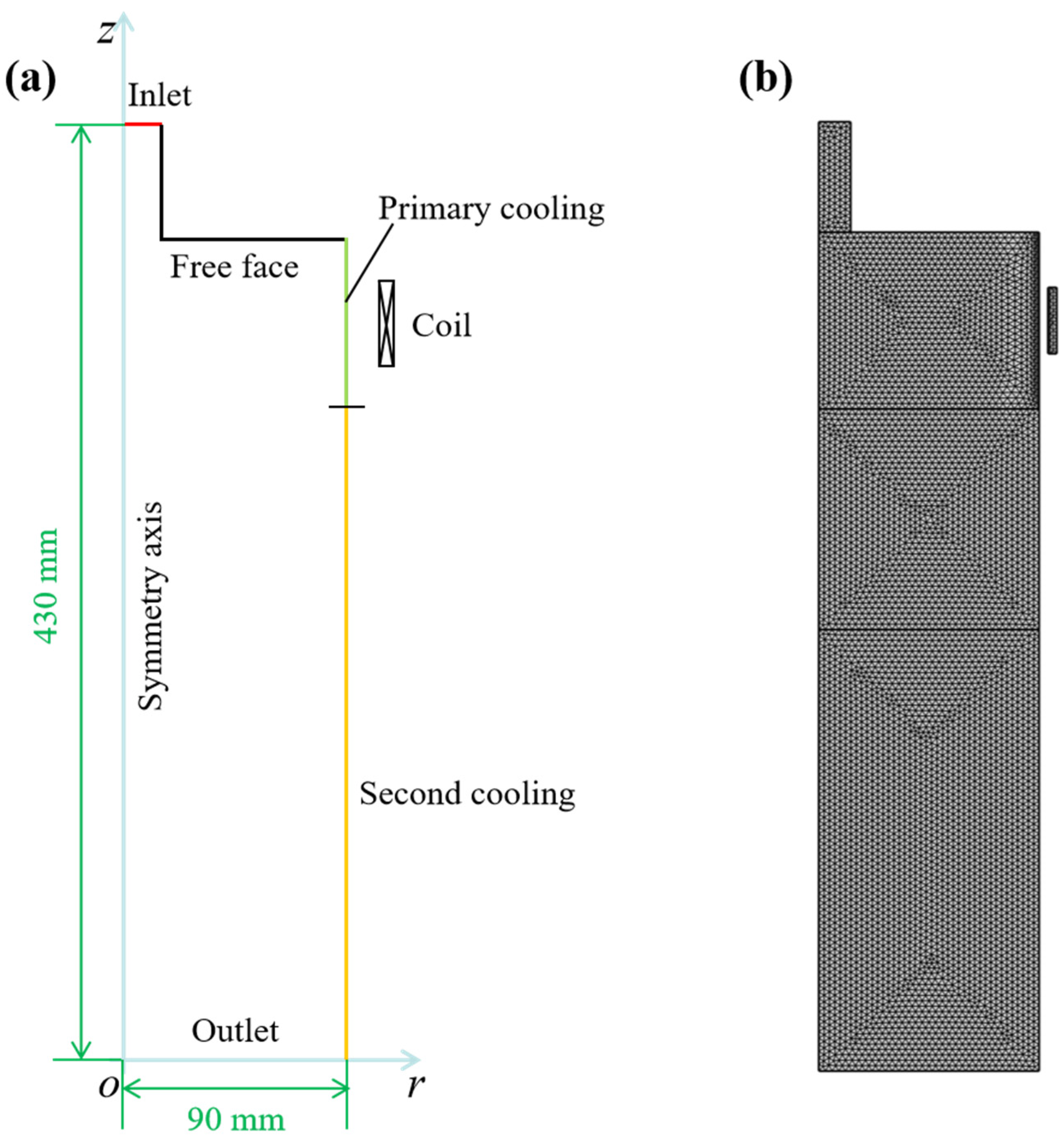
2. Materials and Methods
2.1. Experimental
2.2. Governing Equations
2.3. Boundary Conditions
3. Results
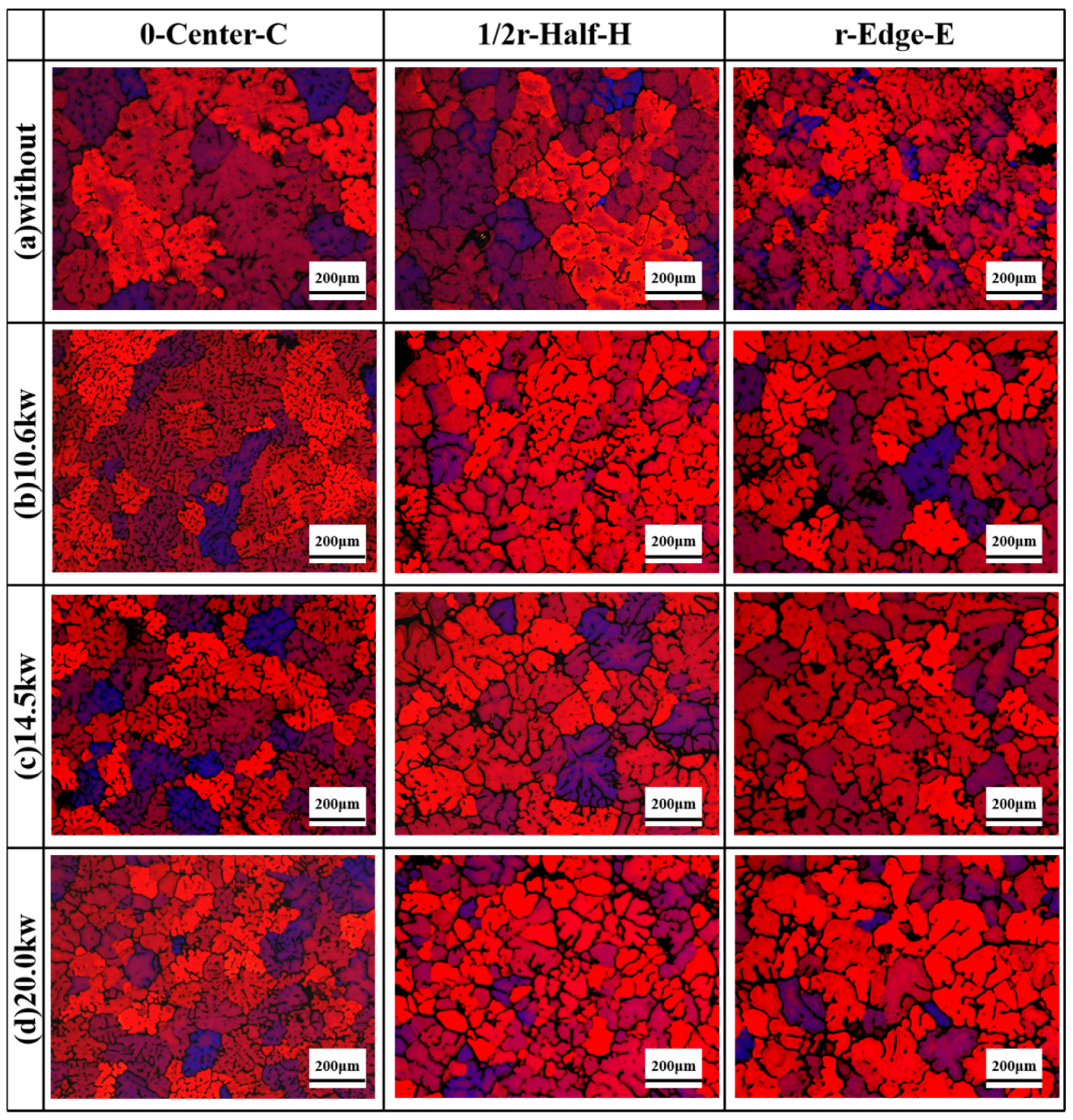
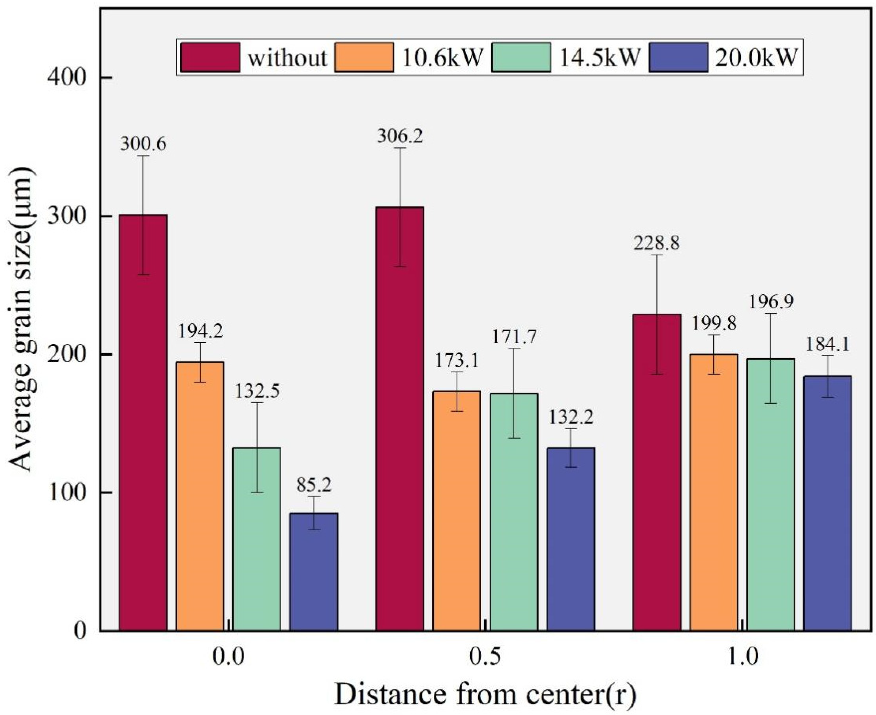
3.1. Microstructure
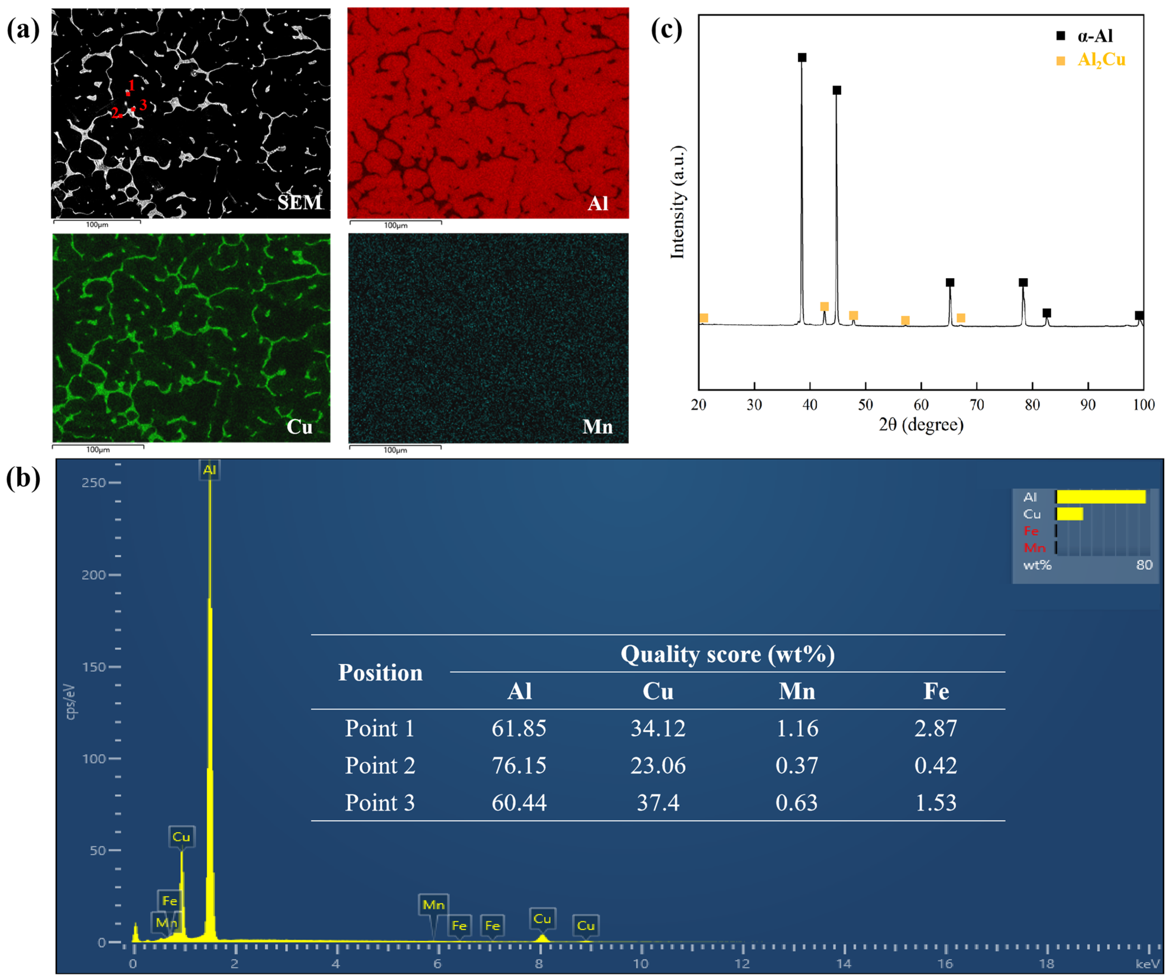
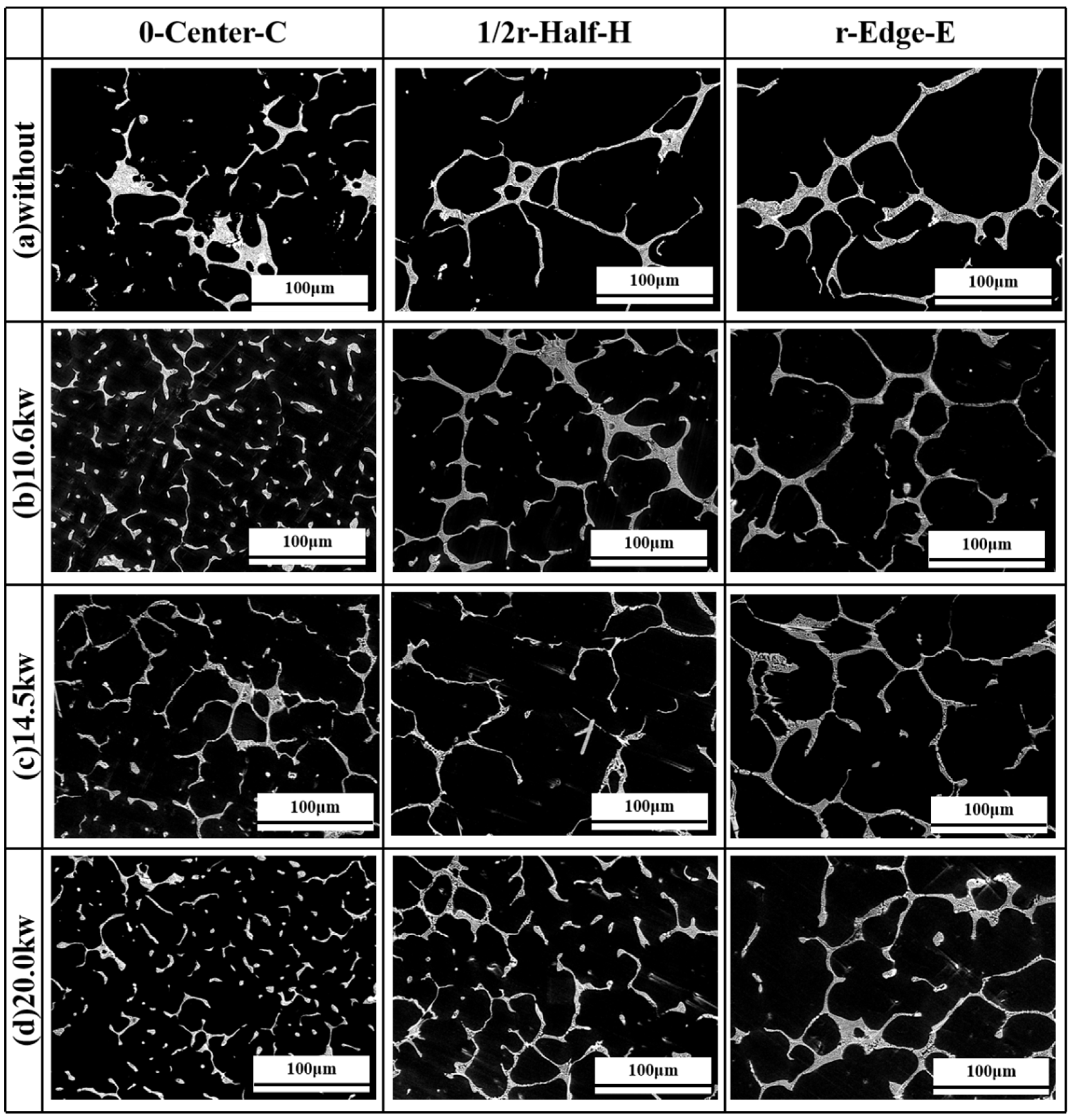
3.2. Distribution Characteristic of Eutectic Phase
3.3. Mechanical Properties
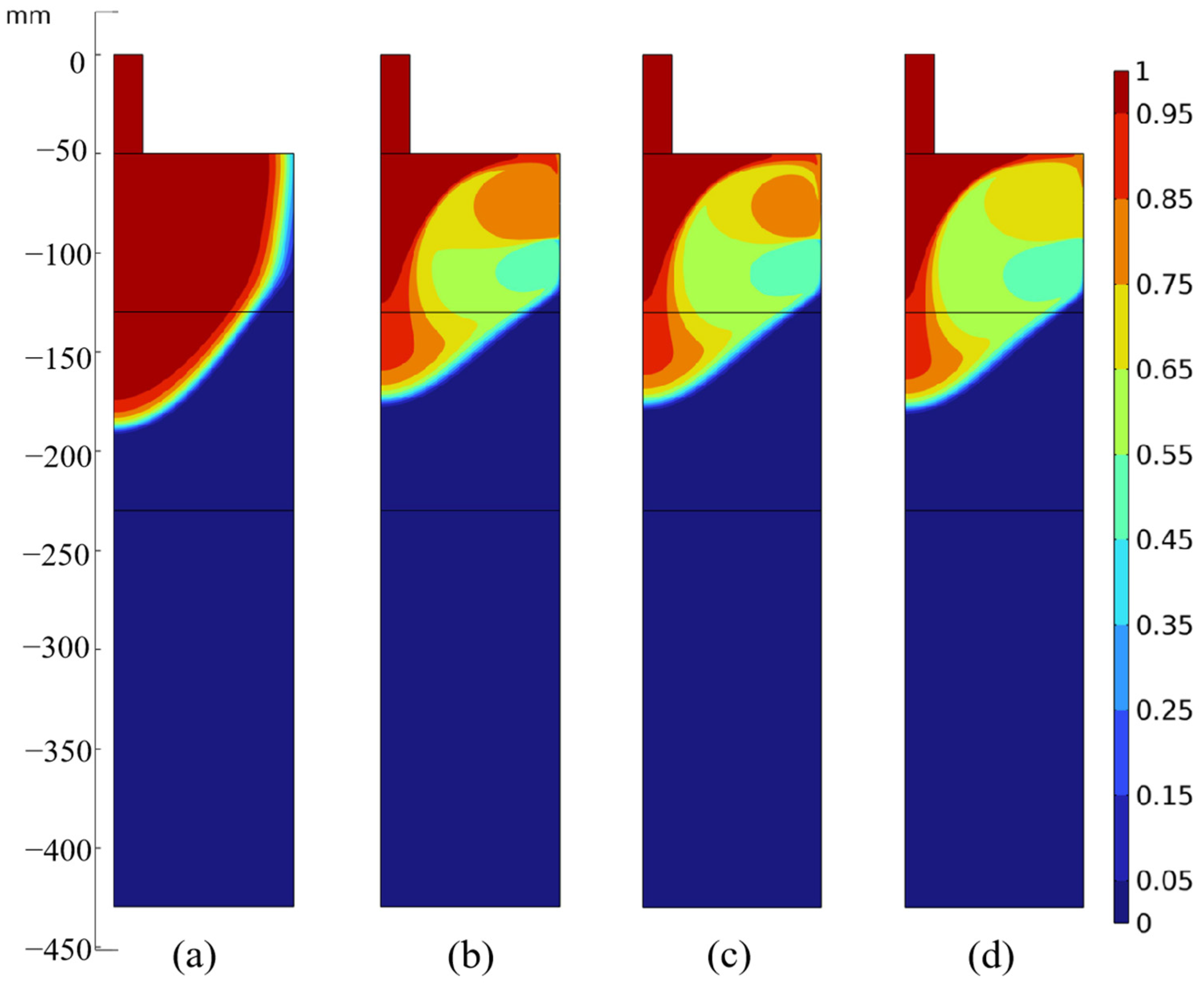
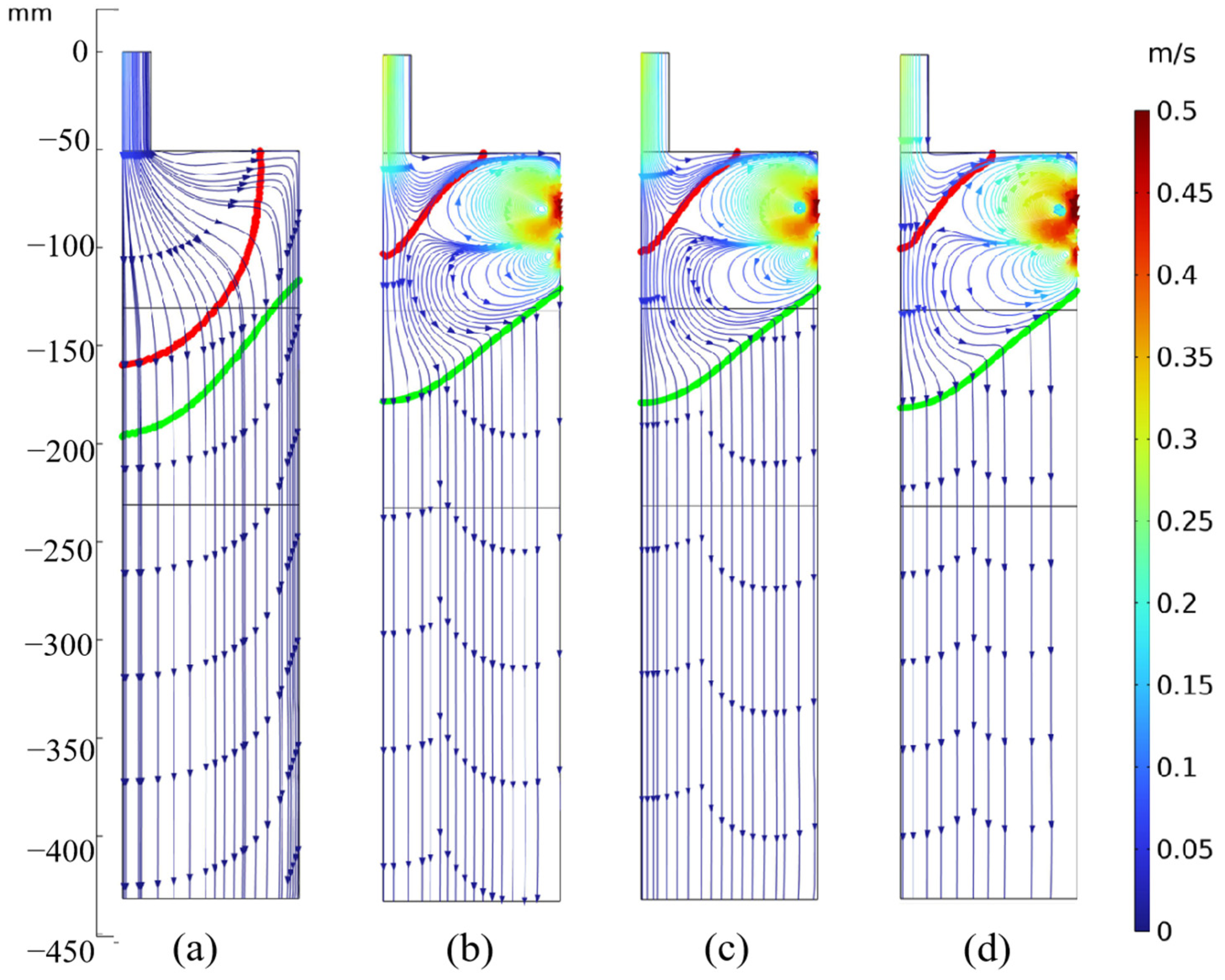
4. Discussion
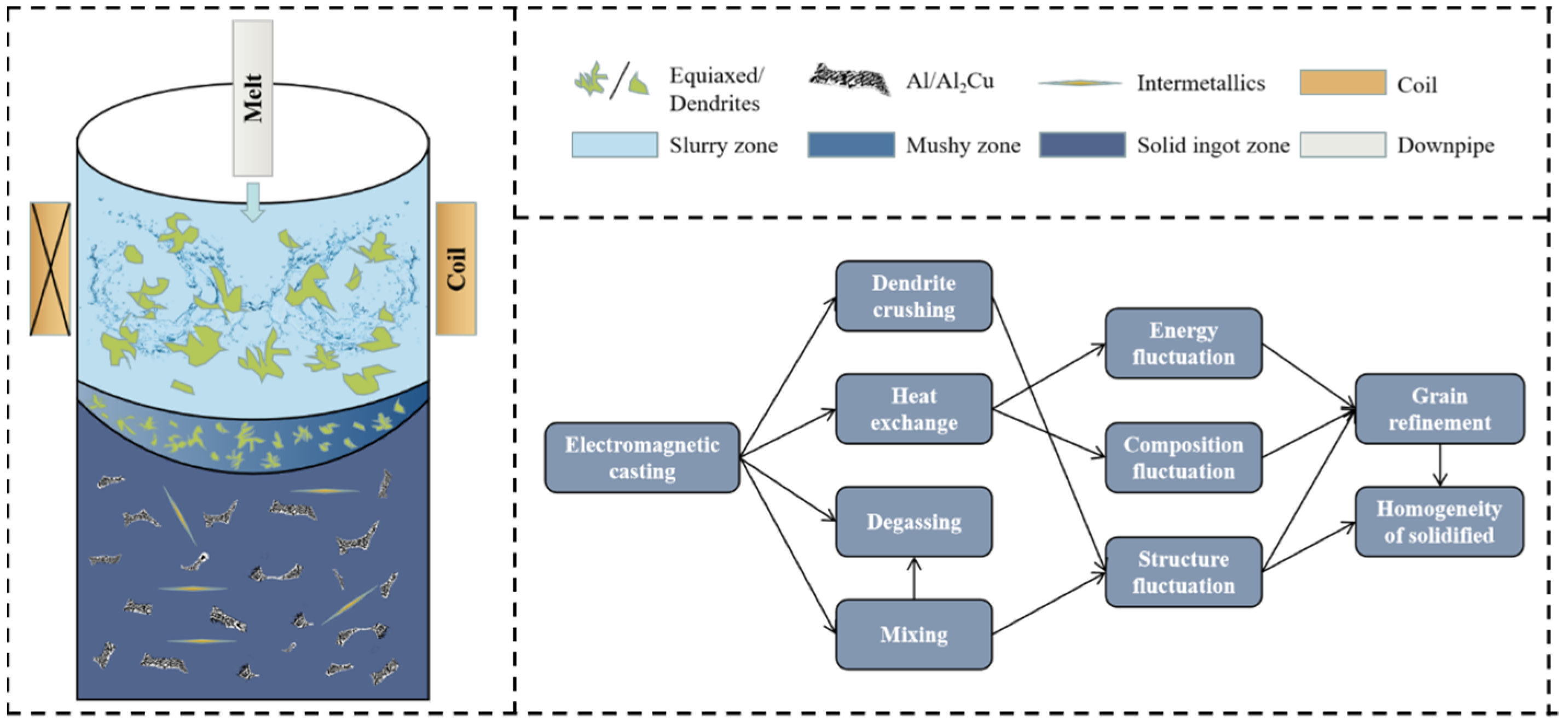
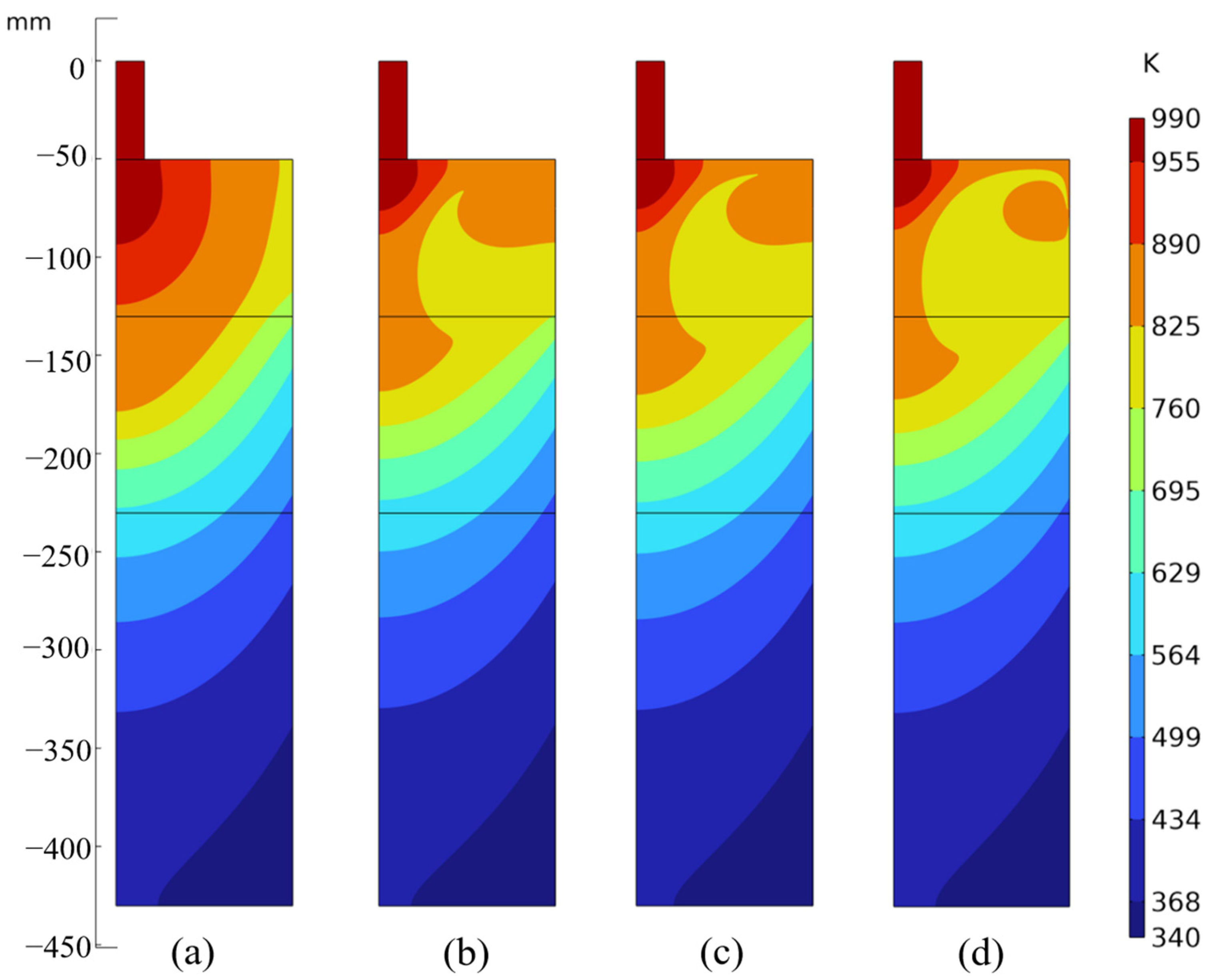
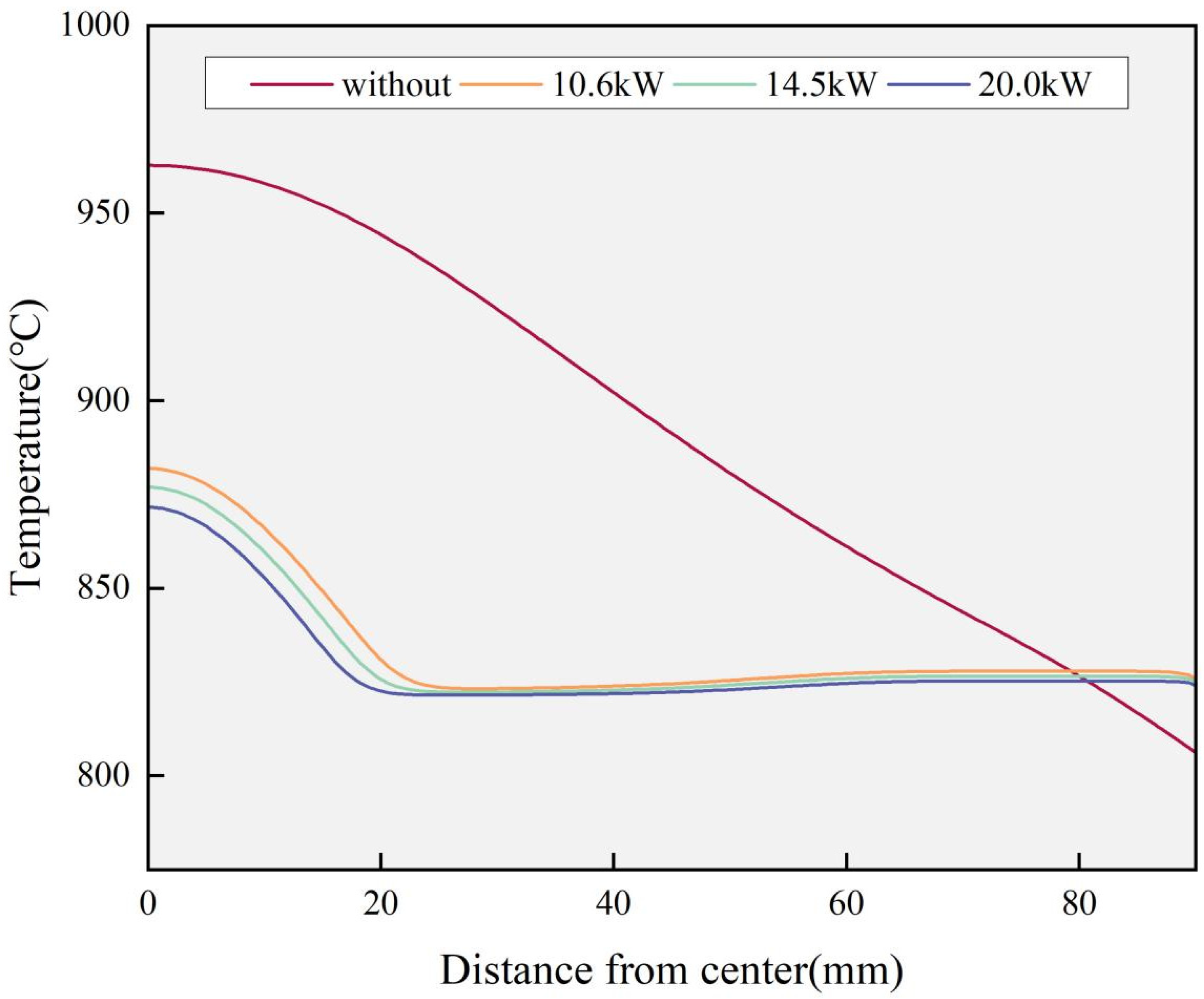
4.1. Effect of Physical Field on Grains
4.2. Effect of Physical Field on Eutectic Phase
4.3. Effect of Physical Field on Mechanical Properties
5. Conclusions
- (1)
- An electromagnetic field can lead to a reduction in grain size when compared to traditional ingots. At the core position with a power of 20.0 kW, the maximum efficiency of grain refinement for α-Al grains was from 300.6 μm to 85.2 μm. Furthermore, the segregation phenomenon of the ingot showed significant improvement, with the segregation index ΔC not exceeding 0.014 at a power of 20.0 kW.
- (2)
- The mechanical properties of 2219 Al-alloy were significantly enhanced by the electromagnetic field. The optimal comprehensive mechanical performance of the ingot was achieved at a power level of 20.0 kW. The tensile strength, yield strength, and elongation at the center increased from 189.6 MPa to 249.9 MPa, 112.1 MPa to 164.4 MPa, and from 6.25% to 10.62%, respectively.
- (3)
- The distribution of the temperature field in the casting process was significantly influenced by the electromagnetic field. The field accelerated the exchange of heat between the central position and the edge, resulting in a reduction in the temperature gradient. Additionally, it helped in making the liquid cavities shallower. Moreover, the electromagnetic field was capable of enhancing the flow rate and increasing the distance between the solid–liquid interface, which ultimately led to an expansion of the paste zone. The Lorentz force generated by the electromagnetic field could drive the stirring of the paste zone, which was effective in crushing dendrites, promoting composition mixing, and improving the segregation phenomenon.
- (4)
- With an increase in electromagnetic power, the stirring of the melt increased and the melt sped up. This led to more thorough stirring of the melt at the center, further increasing the system energy and enhancing the strengthening effect. As a result, better organization and mechanical properties were obtained at 20.0 kW, and the segregation phenomenon was further improved.
Author Contributions
Funding
Data Availability Statement
Acknowledgments
Conflicts of Interest
References
- Tzoumakis, G.; Fotopoulos, K.; Lampeas, G. Multi-Physics Digital Model of an Aluminum 2219 Liquid Hydrogen Aircraft Tank. Aerospace 2024, 11, 161. [Google Scholar] [CrossRef]
- Teng, L.; Lu, X.; Luan, Y.; Sun, S. Predicting Axial Force in Friction Stir Welding Thick 2219 Aluminum Alloy Plate. Int. J. Adv. Manuf. Technol. 2023, 126, 1025–1034. [Google Scholar] [CrossRef]
- He, W.; Hu, Y.; Wu, Z.; Wang, F.; Meng, F.; Lin, Y.; Wang, G.; Wu, S. Defect Sensitivity and High-Cycle Fatigue Resistance of Arc-Welded 2219 Aluminum Alloy at 77 K. Int. J. Fatigue 2024, 182, 108189. [Google Scholar] [CrossRef]
- Zhang, T.; Chen, J.; Gong, H.; Li, H. Study on Residual Stresses of 2219 Aluminum Alloy with TIG Welding and Its Reduction by Shot Peening. Metals 2023, 13, 1581. [Google Scholar] [CrossRef]
- Wan, S.; Su, H.; Shao, B.; Zong, Y.; Shan, D.; Guo, B. Changes in Microstructure and Mechanical Properties of 2219 Al Alloy during Hot Extrusion and Post-Extrusion Aging. J. Mater. Res. Technol. 2023, 24, 3453–3463. [Google Scholar] [CrossRef]
- Qiu, Y.; Zheng, K.; Li, X.; Luo, Y.; Xia, P.; Liu, M.; Zhou, N.; Jia, Y. Processing Map of 2219 Al Alloy Prepared by Internal Electromagnetic Stirring Direct Chill Casting. J. Mater. Res. Technol. 2022, 18, 2885–2895. [Google Scholar] [CrossRef]
- Murthy, N.V.; Prasad Reddy, A.; Selvaraj, N.; Rao, C.S.P. Dispersion of Alumina Nano Particles in Al 2219 Alloy by Ultrasonic Assisted Stir Casting Technique. Mater. Today Proc. 2017, 4, 10113–10117. [Google Scholar] [CrossRef]
- Huang, J.; Hao, K.; Xu, L.; Han, Y.; Zhao, L.; Ren, W. Grain Refinement of Laser-Arc Hybrid Welded 2219 Aluminum Alloy by Introducing TiB2 Particles Employing Laser Pre-Cladding. J. Mater. Res. Technol. 2023, 27, 194–199. [Google Scholar] [CrossRef]
- Walinjkar, D.; Rao, A.K.P. C-DC and MC–DC Casting of Al-Alloys—A Comsol Approach. Mater. Lett. 2015, 161, 698–700. [Google Scholar] [CrossRef]
- Li, R.; Liu, Z.; Chen, P.; Zhong, Z.; Li, X. Investigation on the Manufacture of a Large-Scale Aluminum Alloy Ingot: Microstructure and Macrosegregation: Manufacture of a Large-Scale Al Alloy Ingot. Adv. Eng. Mater. 2017, 19, 1600375. [Google Scholar] [CrossRef]
- Mohanty, P.S.; Gruzleski, J.E. Mechanism of Grain Refinement in Aluminium. Acta Metall. Mater. 1995, 43, 2001–2012. [Google Scholar] [CrossRef]
- Wang, F.; Wang, X.; Cui, J. Effect of Low-Frequency Electromagnetic Casting on Micro-Structure and Macro-Segregation of 5A90 Alloy Ingots. Materials 2020, 13, 2720. [Google Scholar] [CrossRef] [PubMed]
- Wang, Y.; Zhao, S.; Guo, Y. Numerical Simulation and Experimental Investigation of the Preparation of Aluminium Alloy 2A50 Semi-Solid Billet by Electromagnetic Stirring. Materials 2020, 13, 5470. [Google Scholar] [CrossRef]
- Hosseini, S.M.; Amani, E. An Improved Combination of Ruler and Local Electromagnetic Brakes for Continuous Casting Process. J. Manuf. Process. 2023, 85, 1037–1053. [Google Scholar] [CrossRef]
- Wang, F.; Wang, X.; Cui, J. Micro-Structure and Mechanical Properties of 2A97 Al-Li Alloy Cast by Low-Frequency Electromagnetic Casting. Metals 2019, 9, 822. [Google Scholar] [CrossRef]
- Zhao, H.; Zhang, Z.; Li, B.; Bai, Y.; Gao, M. Grain Size and Macrosegregation Control of Large-Sized AA2219 Billets by Internal Electromagnetic Stirring in DC Casting. Front. Mater. 2022, 9, 892765. [Google Scholar] [CrossRef]
- Bondareva, N.S.; Sheremet, M.A. Natural Convection Heat Transfer Combined with Melting Process in a Cubical Cavity under the Effects of Uniform Inclined Magnetic Field and Local Heat Source. Int. J. Heat Mass Transf. 2017, 108, 1057–1067. [Google Scholar] [CrossRef]
- Qiu, Y.; Li, X.; Liu, M.; Zhou, N.; Zheng, K. Effects of Intercooling Intensity on Temperature Field and Microstructure of Large-Scale 2219 Al Alloy Billet Prepared by Internal Electromagnetic Stirring Casting. Materials 2022, 15, 1809. [Google Scholar] [CrossRef]
- Zhou, Z.; Yang, Y.; Duan, W.; Zhang, Z.; Cui, J. Numerical Simulation of DC Casting of Large-Size Rare Earth Magnesium Alloy Ingot under Low-Frequency Electromagnetic Field. Int. J. Adv. Manuf. Technol. 2022, 122, 1367–1381. [Google Scholar] [CrossRef]
- Zhang, L.; Li, X.; Li, R.; Jiang, R.; Zhang, L. Effects of High-Intensity Ultrasound on the Microstructures and Mechanical Properties of Ultra-Large 2219 Al Alloy Ingot. Mater. Sci. Eng. A 2019, 763, 138154. [Google Scholar] [CrossRef]
- ASTM E112-10; Standard Test Methods for Determining Average Grain Size. ASTM International: West Conshohocken, PA, USA, 2010.
- Hatić, V.; Mavrič, B.; Košnik, N.; Šarler, B. Simulation of Direct Chill Casting under the Influence of a Low-Frequency Electromagnetic Field. Appl. Math. Model. 2018, 54, 170–188. [Google Scholar] [CrossRef]
- Jia, Y.; Wang, H.; Le, Q. Transient Coupling Simulation of Multi-Physical Field during Pulse Electromagnetic Direct-Chill Casting of AZ80 Magnesium Alloy. Int. J. Heat Mass Transf. 2019, 143, 118524. [Google Scholar] [CrossRef]
- Maurya, A.; Jha, P.K. Two-Phase Analysis of Interface Level Fluctuation in Continuous Casting Mold with Electromagnetic Stirring. Int. J. Numer. Methods Heat Fluid Flow 2018, 28, 2036–2051. [Google Scholar] [CrossRef]
- Maurya, A.; Kumar, R.; Jha, P.K. Simulation of Electromagnetic Field and Its Effect during Electromagnetic Stirring in Continuous Casting Mold. J. Manuf. Process. 2020, 60, 596–607. [Google Scholar] [CrossRef]
- Chen, X.; Jia, Y.; Le, Q.; Yu, F. Understanding the Influence of Ultrasonic Streaming on Solidification of AZ80 Magnesium Alloy during Direct-Chill Casting Using a Transient Coupling Modeling. J. Mater. Res. Technol. 2021, 14, 1154–1166. [Google Scholar] [CrossRef]
- Kang, K.-G.; Ryou, H.-S.; Hur, N.-K. Coupled Turbulent Flow, Heat, and Solute Transport in Continuous Casting Processes with an Electromagnetic Brake. Numer. Heat Transf. Part A Appl. 2005, 48, 461–481. [Google Scholar] [CrossRef]
- Weckman, D.C.; Niessen, P. A Numerical Simulation of the D.C. Continuous Casting Process Including Nucleate Boiling Heat Transfer. Metall. Mater. Trans. B 1982, 13, 593–602. [Google Scholar] [CrossRef]
- Zhang, L.; Li, R.; Jiang, R.; Zhang, L.; Li, X. A Comparative Study on the Effect of Four-Source Ultrasonic Power on the Microstructure and Mechanical Properties of Large-Scale 2219 Aluminum Ingots. JOM 2019, 71, 2063–2071. [Google Scholar] [CrossRef]
- Nadella, R.; Eskin, D.G.; Du, Q.; Katgerman, L. Macrosegregation in Direct-Chill Casting of Aluminium Alloys. Prog. Mater. Sci. 2008, 53, 421–480. [Google Scholar] [CrossRef]
- Wang, F.; Ren, Y.; Wang, S.; Zhang, S.; Gao, H.; Fu, C.; Zhang, Z.; Cui, J. Microstructure and Tensile Properties of 5A90 Al–Mg–Li Alloy Containing Minor Sc Cast by Low-Frequency Electromagnetic Casting. J. Mater. Res. Technol. 2023, 24, 5782–5791. [Google Scholar] [CrossRef]
- Menapace, C.; Fioretta, L.; Straffelini, G.; Canevari, L.; Sannicolò, S. Microstructural Characterisation and Hot-Deformation Behaviour of AA6082 Al Alloy Produced by Low-Frequency Electromagnetic Casting. J. Mater. Eng. Perform. 2020, 29, 2667–2678. [Google Scholar] [CrossRef]
- Liotti, E.; Lui, A.; Vincent, R.; Kumar, S.; Guo, Z.; Connolley, T.; Dolbnya, I.P.; Hart, M.; Arnberg, L.; Mathiesen, R.H.; et al. A Synchrotron X-ray Radiography Study of Dendrite Fragmentation Induced by a Pulsed Electromagnetic Field in an Al–15Cu Alloy. Acta Mater. 2014, 70, 228–239. [Google Scholar] [CrossRef]
- Jung, J.-G.; Lee, J.-M.; Cho, Y.-H.; Yoon, W.-H. Combined Effects of Ultrasonic Melt Treatment, Si Addition and Solution Treatment on the Microstructure and Tensile Properties of Multicomponent Al Si Alloys. J. Alloys Compd. 2017, 693, 201–210. [Google Scholar] [CrossRef]
- Sun, N.; Patterson, B.R.; Suni, J.P.; Simielli, E.A.; Weiland, H.; Allard, L.F. Microstructural Evolution in Twin Roll Cast AA3105 during Homogenization. Mater. Sci. Eng. A 2006, 416, 232–239. [Google Scholar] [CrossRef]
- Hansen, N. Hall–Petch Relation and Boundary Strengthening. Scr. Mater. 2004, 51, 801–806. [Google Scholar] [CrossRef]
- Wolczynski, W. Back-Diffusion Phenomenon during the Crystal Growth by the Bridgman Method, Chapter 2. In Modelling of Transport Phenomena in Crystal Growth; Szmyd, J.S., Suzuki, K., Eds.; WIT Press: Southampton, UK; Boston, MA, USA, 2000; pp. 19–59. [Google Scholar]
- Wołczyński, W. Nature of Segregation in the Steel Static and Brass Continuously Cast Ingots. Arch. Metall. Mater. 2018, 63, 1915–1922. [Google Scholar] [CrossRef]
- Al-Helal, K.; Chang, I.; Patel, J.B.; Fan, Z. Thermomechanical Treatment of High-Shear Melt-Conditioned Twin-Roll Cast Strip of Recycled AA5754 Alloy. JOM 2019, 71, 2018–2024. [Google Scholar] [CrossRef]


| Cu | Mn | Zr | Ti | V | Fe | Si | Mg | Zn | Al |
|---|---|---|---|---|---|---|---|---|---|
| 5.80–6.80 | 0.20–0.40 | 0.10–0.25 | 0.02–0.10 | 0.05–0.15 | ≤0.30 | ≤0.20 | ≤0.02 | ≤0.10 | Bal. |
| Items | Value (unit) |
|---|---|
| Casting speed, Ucast | 60 (mm/min) |
| Melting point of alloy, Tm | 818 (K) |
| Environment temperature, Text | 293 (K) |
| Cooling water temperature, Twater | 293 (K) |
| Solidus temperature, TS | 787 (K) |
| Liquid temperature, TL | 916 (K) |
| Latent heat, dH | 360 (KJ/kg) |
| Mushy zone constant, Amush | 105 |
| χ | 0.001 |
| Heat transfer coefficient (primary cooling zone), hmold | 1500 (W/m2·K) |
| Heat transfer coefficient(air), hair | 50 (W/m2·K) |
| Samples | Position | |||||
|---|---|---|---|---|---|---|
| 0 | RE (%) | 1/2r | RE (%) | r | RE (%) | |
| Without (μm) | 300.6 | - | 306.2 | - | 228.8 | - |
| 10.6 kW (μm) | 194.2 | 35.4 | 173.1 | 43.5 | 199.8 | 12.7 |
| 14.5 kW (μm) | 132.4 | 55.7 | 171.7 | 43.9 | 196.9 | 14.0 |
| 20.0 kW (μm) | 85.2 | 71.7 | 132.2 | 56.8 | 184.1 | 19.5 |
| Position | |||
|---|---|---|---|
| 0 | 1/2r | r | |
| Without | 0.068 | 0.059 | −0.128 |
| 10.6 kW | 0.024 | 0.022 | −0.047 |
| 14.5 kW | 0.017 | 0.010 | −0.027 |
| 20.0 kW | 0.014 | −0.007 | −0.008 |
Disclaimer/Publisher’s Note: The statements, opinions and data contained in all publications are solely those of the individual author(s) and contributor(s) and not of MDPI and/or the editor(s). MDPI and/or the editor(s) disclaim responsibility for any injury to people or property resulting from any ideas, methods, instructions or products referred to in the content. |
© 2024 by the authors. Licensee MDPI, Basel, Switzerland. This article is an open access article distributed under the terms and conditions of the Creative Commons Attribution (CC BY) license (https://creativecommons.org/licenses/by/4.0/).
Share and Cite
Jiang, M.; Xu, D.; Ya, B.; Meng, L.; Zhu, M.; Shan, C.; Zhang, X. Effect of Electromagnetic Power on the Microstructure and Properties of 2219 Aluminum Alloy in Electromagnetic Continuous Casting Technology. Metals 2024, 14, 393. https://doi.org/10.3390/met14040393
Jiang M, Xu D, Ya B, Meng L, Zhu M, Shan C, Zhang X. Effect of Electromagnetic Power on the Microstructure and Properties of 2219 Aluminum Alloy in Electromagnetic Continuous Casting Technology. Metals. 2024; 14(4):393. https://doi.org/10.3390/met14040393
Chicago/Turabian StyleJiang, Mingxi, Dazhao Xu, Bin Ya, Linggang Meng, Mengqi Zhu, Changzhi Shan, and Xingguo Zhang. 2024. "Effect of Electromagnetic Power on the Microstructure and Properties of 2219 Aluminum Alloy in Electromagnetic Continuous Casting Technology" Metals 14, no. 4: 393. https://doi.org/10.3390/met14040393