Article

On Dynamic Recrystallization during the Friction Stir Processing of Commercially Pure Ti and Its Influence on the Microstructure and Mechanical Properties

by
Michael Regev
1,* and
Stefano Spigarelli
2
1
Department of Mechanical Engineering, Braude College, P.O. Box 78, Karmiel 2161002, Israel
2
DIISM, Università Politecnica delle Marche, 60131 Ancona, Italy
*
Author to whom correspondence should be addressed.
Metals 2024, 14(6), 644; https://doi.org/10.3390/met14060644
Submission received: 8 May 2024 / Revised: 26 May 2024 / Accepted: 27 May 2024 / Published: 28 May 2024

Abstract

:
Friction stir processing (FSP), a severe plastic deformation process, was applied on commercially pure Ti to obtain an improved microstructure. The process yielded a refined microstructure and higher mechanical properties at room temperature (RT). Yet the microstructure was found to contain bright bands demonstrating high hardness values of about 500 HV. High-resolution scanning electron microscopy (HRSEM) as well as electron backscattering diffraction (EBSD) analysis indicated that these bands were composed of extra-fine equiaxed α-Ti grains with an average radius of 1–2 microns. In addition, a retained β phase was detected at the boundaries of these α-Ti grains, together with a small quantity of separate β grains. The results of a fractography study conducted on broken tensile specimens showed that the material that underwent FSP was free of defects and that the fracture started at these bands. It is proposed that these bright bands are due to excessive deformation occurring during the processing stage, leading to an accelerated dynamic recrystallization (DRX) process. In turn, these heavy deformation regions act as a strengthening constituent, making the material superior to the parent material as far as its mechanical RT properties are concerned. Consequently, this means that the FSP of CP-Ti has the potential to serve as an industrial means of improving the mechanical properties of the material.

Graphical Abstract

1. Introduction

The specific strength, heat resistance, erosion and corrosion resistance of titanium and its alloys are well known [1,2,3,4,5,6,7,8,9,10,11,12,13,14,15]. A friction stir processing process (FSP) was derived from friction stir welding (FSW). It was first described by Mishra et al. [16] in 2000. In FSP, the rotating tool does not weld the parts to each other as in FSW. The purpose of FSP is to produce a very fine grain size stir zone through severe plastic deformation, in order to improve the mechanical properties of the material. The use of FSP for improving the mechanical properties of titanium products was also reported with reference to additive manufacturing [17]. Applying FSW, and hence FSP, to Ti and its alloys is somewhat challenging due to the high melting temperature of titanium (1668 °C), thus requiring welding tool materials that are more resistant to temperature and wear [3,7,8,9,10,11,12,13,18,19,20,21,22,23,24].
Several studies, among them [8,9,10,11,12,13,14,24,25], have examined the microstructure obtained during the FSP of commercially pure (CP) Ti. Yet these studies are marked by many discrepancies, including the sizes and shapes of the grains as well as the influence of the processing parameters on grain shape and size and the metallurgical processes involved. Several researchers mentioned the occurrence of DRX during FSP. Bahl et al. [8], who processed the material at rotational speeds of 600 and 1250 rpm and a transverse speed of 200 mm/min, reported on grain refinement at the SZ from 57 µm down to 19 µm and 13 µm for 600 and 1250 rpm, respectively. They claimed that Ti, which has a high stacking-fault energy (SFE), tends to undergo geometric dynamic recrystallization (GDRX) and continuous dynamic recrystallization (CDRX) rather than discontinuous dynamic recrystallization (DDRX). Yet they also noted the occurrence of grain boundary bulging at the stir zone (SZ) as an indication that DDRX took place to some extent and therefore concluded that all three types of DRX are responsible for grain refinement. Jiang et al. [9] reported an average grain size of 33.1 μm in the case of the PM, which decreased to 5.8 μm in the case of processing at 180 rpm, whereas processing at 270 rpm yielded a bimodal grain size distribution with an average value of 13 μm on the surface and 9.3 μm at 1 mm deep. Singh et al. [10] reported grain refinement from 11.61 ± 6.69 μm down to about 1 μm at the SZ, using processing parameters of 600 rpm and 350 mm/min. Vakili-Azghandi et al. [11] processed the material at 1400 rpm and 14 mm/min. They reported grain refinement down to 4.5 μm after the first FSP pass and further refinement down to 3.1 μm together with the formation of a Widmanstätten structure after the third pass. In a recent publication of Vakili-Azghandi et al. on the FSP of CP Ti [25], they reported an average grain size of 3.8 μm at the SZ. However, they did not report anything about the BM grain size. Fattah-alhosseini et al. [12] processed the material at a rotational speed of 1400 rpm and a transverse speed of 40 mm/min. They also reported more extensive grain refinement when the number of passes was increased from an average BM grain size of 25 μm down to submicron size after three passes, though they did not state the exact grain size obtained after FSP. Zhang et al. [14] processed the material at 200–400 rpm and 60–120 mm/min. They reported that the microstructure of the BM consisted of equiaxed grains with an average size of ~38 μm, while the SZ consisted of fine grains with an average grain size of ~6 μm. According to Zhang et al. [14], both CDRX and DDRX took place at the SZ. Nevertheless, the consensus among researchers seems to be that the development of the microstructure during FSW is a complex, multi-stage process that is based on various types of DRX, as stated in the reviews by Sajid et al. [24], Zykove et al. [26] and Ding et al. [27].
In this study, CP Ti grade 2 is examined due to its superior corrosion resistance compared to other grades of CP-Ti as well as its high mechanical tensile strength and hardness [28]. Previous studies conducted by the authors on CP-Ti grade 2 that underwent FSW [29,30] indicated that the weld was not the weakest link, either at high temperatures or at RT. Both for tensile tests conducted at RT and for creep tests conducted at high temperatures, failure always occurred at the parent material (PM) rather than at the weld. This led to the conclusion that FSP has the potential to produce an improved microstructure and hence to yield improved mechanical properties. In all cases reported, the consensus in the literature seems to be that both the hardness [9,10,11,13] and the tensile properties [9] of the material subjected to FSP are higher than those of the PM. With respect to fractography, the only reported fractography study was in Jiang et al. [9], and this study was quite limited.
Materials subjected to FSP are compared to their parent materials in terms of tension and hardness at RT, as well as fractography, in the current study. The microstructure of CP-Ti that underwent FSW and hence of CP-Ti that underwent FSP has been discussed in the authors’ previous publications [29,30]. As mentioned in those publications, heavy deformation bands characterized by very high hardness values and extra-fine grains were detected. Neither these bands nor their influence on the mechanical properties of the material subjected to FSP have been noted in any of the references mentioned, motivating the decision to study these bands and their origin. The current study focuses on the microstructure of these deformation bands and their influence on the mechanical properties. The main finding of the current study is that the microstructure of the cross-section as well as its mechanical properties are not uniform either longitudinally or transversally. Besides demonstrating superior strength, the shape and distribution of these bands changed along the processed strip. As stated, the special structure and properties of these deformation bands as well as their changing distribution have not been mentioned in any previous publications dealing with the FSP of CP-Ti.
HRSEM as well as EBSD analysis carried out on these bands revealed that they were composed of extra-fine equiaxed α-Ti grains having an average radius of 1–2 microns. In addition, a retained β phase was detected at the grain boundaries of these α-Ti, together with a small quantity of separate β grains. The material subjected to FSP was free of defects and the fracture initiated at these bands, according to the fractography results on broken tensile specimens. According to this model, the grains mentioned above were formed due to DRX taking place during FSP. The retained β phase at the grain boundaries and in a few cases as separate β grains shows that the α-β phase transformation temperature of about 880 °C in the case of pure Ti was reached during FSP. The microstructure observed in the current study at these bands, namely a sort of α + β extra-fine equiaxed grain microstructure, is a result of increased deformation during FSP. This in turn led to excessive DRX resulting in a higher degree of grain refinement, while the α-β phase transformation contributed to an even higher degree of grain refinement.
According to the results of this study, the material subjected to FSP showed superior mechanical properties at room temperature when compared with its parent material. This means, in turn, that the FSP of CP-Ti has the potential to become an industrial means of improving the mechanical properties of the material. Several questions still require further research: How stable is this microstructure at high temperatures? Is the correct selection of process parameters capable of yielding a uniform cross-section composed entirely of the α + β extra-fine microstructure, as observed at the excessive deformation regions detected?

2. Materials and Methods

2.1. Material Processing

The material used for this study was commercially pure (CP) Ti grade 2 with an ultimate tensile strength close to 500 MPa in the form of 200 mm × 200 mm plates, 3 mm thick. The plate’s hardness was typical for an annealed Ti CP-2 containing 0.15% O [31]. A SHARNOA CNC milling machine was used to perform FSP on the above plates. The processing tool was made of H-13 tool steel with a 20 mm diameter shoulder and a 2 mm long, 6-mm-diameter WC pin. For FSP, the authors decided to use the same processing tool and parameters they used in their previous studies [29,30] due to their ability to produce a defect-free material subjected to FSP. In the parameter lookup stage, nine rotational and transverse speed combinations were considered. Each material subjected to FSP was tested both metallographically and radiographically. A metallographic study was carried out after extracting metallographic specimens at four different locations along the processed strip under each of these different sets. Readers are referred to [29] for complete information on the nine possible rotational and transverse speeds. In the end, 500 mm/min for the transverse speed and 700 rpm for the rotational speed were selected. A total of 15 plates were then processed; the dimensions of a processed plate can be seen in Figure 1.

2.2. Metallography

Metallographic analysis was performed using a Zeiss AX10 optical microscope (Carl Zeiss AG, Oberkochen, Germany) and a Thermo Fisher Scientific Prisma E scanning electron microscope (SEM) equipped with an energy-dispersive X-ray spectroscopy (EDS) system (Thermo Fisher Scientific Inc., Waltham, MA, USA) having an accuracy level higher than 1% for quantitative analysis and a lateral resolution of 1 μm. Electron backscattering diffraction (EBSD) analysis was carried out using a Zeiss Ultra Plus high-resolution (HR) SEM (Carl Zeiss AG, Oberkochen, Germany) equipped with an Oxford X-MAX EDS detector and Bruker QUANTAX EBSD detector. The lateral resolution of the EBSD analysis was similar to that of the EDS, namely 1 μm. A metallographic study was carried out on three different cross-section specimens machined out at three different points along the processed strip—at the first third, second third and final third of the processed strip; the location of the metallographic cross-sections can be seen in Figure 1. The etchant used for both optical metallography and SEM metallography was Kroll’s reagent.

2.3. Mechanical Properties
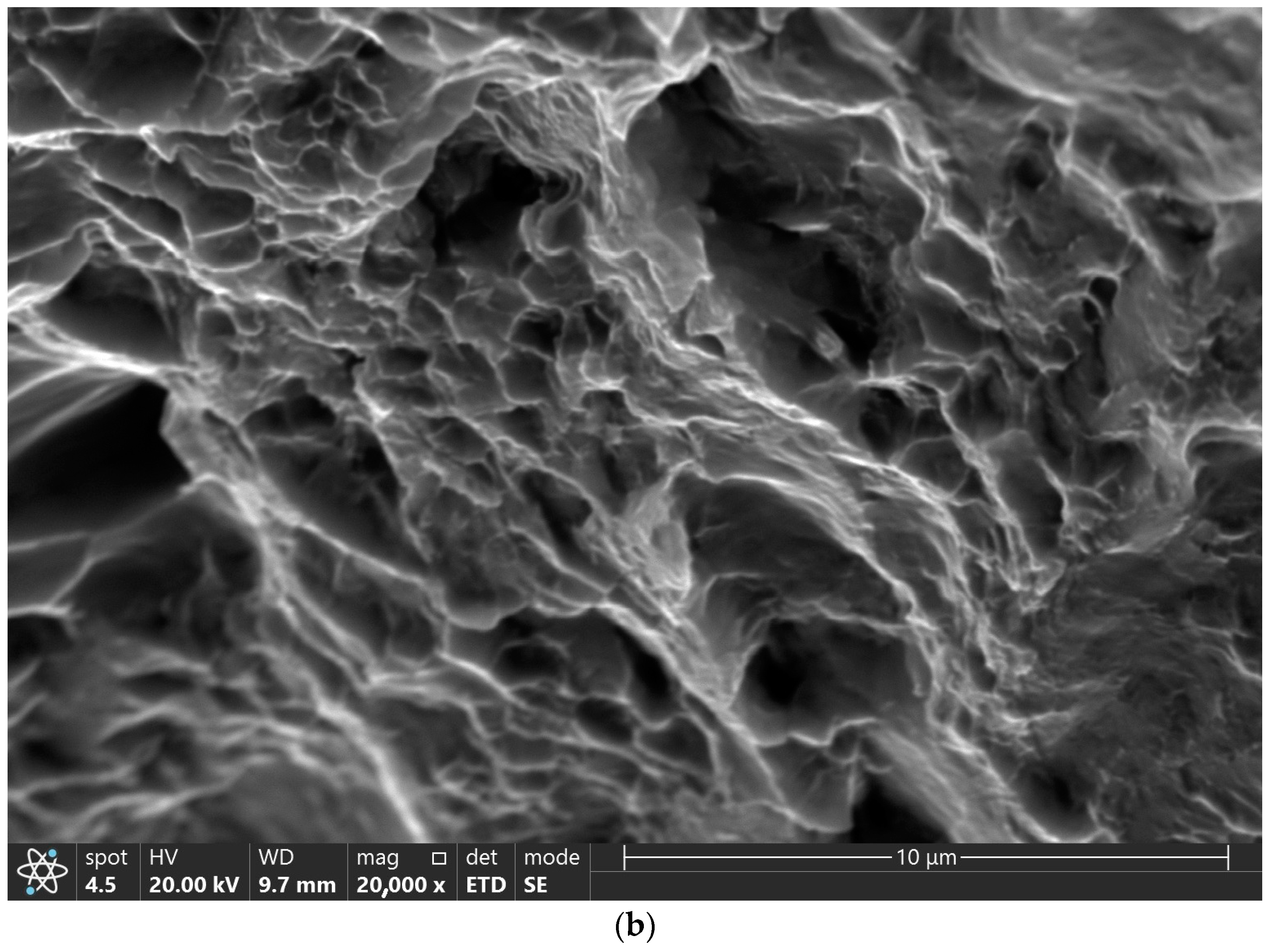
A Shimadzu microhardness tester (Shimadzu Corporation, Kyoto, Japan) was used to measure Vickers microhardness under 200 gf load.
Microhardness testing was carried out on the three metallographic cross-section specimens mentioned above. Each cross-section metallographic specimen provided three microhardness profiles: 0.5 mm above the lower surface, 1.2 mm above the lower surface and 0.5 mm below the upper surface. The measurements were taken perpendicularly to the longitudinal axis of the processed strip while keeping a distance of 0.5 mm between each indentation.
Then, 3 mm × 3 mm square cross-section specimens with a 25 mm gauge length were machined from the FSP region of the plates with the longitudinal axis parallel to the FSP direction. The configuration of the tensile specimens with respect to the welded specimen is shown in Figure 1a, while the dimensions of the tensile specimen are given in Figure 1b. The gauge length was 25 mm, with the center of the processed strip corresponding to the center of the tensile specimen. Five tensile tests were carried out on the parent material (PM), while another five tensile tests were carried out on specimens subjected to FSP.

2.4. Fractography

A Thermo Fisher Scientific Prisma E SEM (Thermo Fisher Scientific Inc., Waltham, MA, USA) was used to examine broken friction-stir-processed tensile specimens for fractography.

3. Results

Figure 2a–c show optical images of three cross-sections taken along the processed strip after the first third, second third and final third of the processed strip, respectively. In addition, bright bands similar to the ones reported in [29] are discernible across the cross-section in all three cases.
A comparison of Figure 2a–c shows that the shape and the dimensions of the bright bands across the cross-section vary along the processed strip. The microhardness mapping of these cross-sections was carried out in order to find correlations with the appearance of these bright bands. Figure 3a–c depict microhardness profiles taken from the specimens shown in Figure 2a–c, respectively. Each of Figure 3a–c depicts three microhardness profiles taken across the processed strip at 0.5 mm above the lower surface, 1.2 mm above the lower surface and 0.5 mm below the upper surface taken perpendicularly to the longitudinal axis of the processed strip while keeping a distance of 0.5 mm between each indentation.
As stated earlier, the diameter of the tool’s pin was 6 mm, indicating in turn that the SZ spanned an area of at least −3 to 3 mm from the centerline. The borders of the SZ are shown by vertical lines in Figure 2a–c.
It can be seen from Figure 3 that the hardness of the processed material is around 200 HV0.2; the microhardness values of profile 1 are markedly higher and reach up to 483 HV0.2. In the case of Figure 2b, profile 2 and profile 1 show higher values that reach 539 HV0.2. All three microhardness profiles shown in Figure 3c exhibit values higher than 400 HV0.2, in some cases even reaching 479 HV0.2.
Figure 4 depicts an SEM micrograph taken from one of the bright bands shown in Figure 2. As can be seen in the figure, most of the grains are fine equiaxed with an average size of one to two microns. In addition, a small fraction of the grains have a fibrous morphology. This structure is discernible in all cases within the above-mentioned bright bands. EDS analyses conducted on the bright bands and on an adjacent region of the stir zone out of the bright band revealed that the chemical composition of both microstructures was pure Ti.
Figure 5a depicts a high-resolution scanning electron microscope (HRSEM) grain map obtained by electron backscattered diffraction (EBSD) taken from one of the bright bands under a magnification of 15,000×, and Figure 5b depicts the respective misorientation angle histogram. The large misorientation angles show that most of the grains are separate grains rather than subgrains. A grain size histogram referring to the same region is shown in Figure 5c. The average grain size according to this histogram is 1.62 μm based on a sample size of 107 grains. Figure 5d depicts a phase map image of the respective region shown in Figure 5a. The red color represents the α-Ti phase, while the green color represents the β-Ti phase. The β-Ti phase is concentrated at the grain boundaries of the α-Ti but also appears as separate grains in a few cases.
Table 1 summarizes the tensile test results for five PM specimens, as well as for five specimens subjected to FSP. It should be noted that the PM tensile test results have already been published elsewhere [28] and are given here for the sake of comparison with the material subjected to FSP.
SEM image 6a shows the fracture surface of a broken tensile specimen that underwent FSP, and Figure 6b shows where the fracture originated at higher magnification. As can be seen from Figure 6a, the fracture surface had a ductile fracture character. Figure 6a also shows that the fracture initiated at the lower right corner of the cross-section, as indicated by the arrow, and propagated upwards and left toward the middle of the cross-section. The size of the dimples shown in Figure 6b varies from less than one micron up to 2–3 microns. No evidence of pre-existing cracks or other defects was detected.

4. Discussion

As stated earlier, the microstructure of Ti subjected to FSW was studied and reported in detail in a previous publication by the authors [29]. Keeping in mind that the microstructure of Ti subjected to FSP corresponds to the stir zone of the material subjected to FSW welded under the same parameters, it is evident that the average grain size of the material that underwent FSP is similar to that of the SZ of the material that underwent FSW, namely several microns compared to the coarse equiaxed grains of the PM, which have an average diameter of 20–30 μm.
In the case of Figure 2a, the bright bands mentioned above appear only at the upper half of the cross-section. Profiles 2 and 3 of Figure 3a show that the average hardness of the processed material is around 200 HV0.2 with relatively small variations, in line with the findings of a previous study [29]. Unlike profiles 2 and 3 of Figure 3a, the microhardness values of profile 1, which was taken next to the upper surface where bright bands can be seen, are markedly higher and reach up to 483 HV0.2. In the case of Figure 2b, no bands are discernible next to the lower surface. Moreover, the values of profile 3 in Figure 3b are in good agreement with the hardness of the processed zone, whereas profile 2 and especially profile 1 show higher values that reach 539 HV0.2 (in the case of profile 1), correlating well with the existence and location of the bright bands. In the case of Figure 2c, the entire cross-section contains bright bands, whereas all three microhardness profiles shown in Figure 3c exhibit values higher than 400 HV0.2, in some cases even reaching 479 HV0.2. The conclusion is that the cross-section is non-homogenous along its depth axis as well as along its longitudinal axis. As shown in Figure 1b, the dimensions of the cross-section of the gauge length of the tensile specimens were 3 × 3, in turn indicating that they were machined out from between −1.5 and 1.5 mm from the centerline. Keeping in mind that the diameter of the processing tool’s pin was 6 mm, one can assume that the whole gauge length of the tensile specimens was within the stir zone (SZ). Nevertheless, Figure 2 and Figure 3 show that both the microstructure and the hardness properties of the tensile specimens differed markedly not only from one another but also along the longitudinal axis of each specimen.
A comparison of the hardness values of the bright bands mentioned above to the findings of other publications shows that they are significantly higher than these of the common microstructure of the stir zone. The maximum hardness value according to Vakili-Azghandi [11] who studied grade 2 CP-Ti was 269 HV after three consecutive FSP passes, while one pass yielded 199 HV. Jiang et al. [9] reported hardness values of up to 190 ± 10 HV, while Singh et al. [10] reported maximum values of 287 HV. In another publication of Singh et al. [13], the authors reported maximum values of 248 ± 20 HV. It should be stated that the exact grade of the CP-Ti plates was not reported in the cases of [9,10,13]; however, the hardness values of the PM reported by Jiang et al. [9] were ~150 HV, while those reported by Singh et al. [10,13] were ~165 which are quite similar to the values of the PM in the current study.
The fine grain size detected within the bright bands seen in Figure 4 leads to the conclusion that these bands are due to extensive grain refinement and therefore show increased hardness. It may be assumed, therefore, that these bright bands are due to a more extensive plastic deformation during FSP and hence a more extensive grain refinement resulting from DRX. As stated earlier, many discrepancies exist among researchers regarding whether all three types of DRX, namely GDRX, CDRX and DDRX [8], are the prevalent microstructure formation process mechanisms or whether the mechanisms are just CDRX and DDRX [14] or Widmanstätten formation [11]. Nonetheless, it seems that except for the bright bands, the microstructure of the PM as reported by the authors [28] and the refined structure within the SZ are in line with the publications mentioned above.
Nevertheless, the above reported grain sizes are still coarser than the average grain size inside the bright bands as measured in the current study. The average grain size was found to be 1.62 μm based on a sample size of 107 grains (see Figure 5c). As stated earlier, the high misorientation angles between the grains (see Figure 5c) show that these are separate grains rather than subgrains. This leads, in turn, to the conclusion that these grains were formed due to DRX taking place during FSP. The retained β phase at the grain boundaries, and in a few cases as separate grains as depicted in the phase map (see Figure 5d), shows that the α-β phase transformation temperature of about 880 °C in the case of pure Ti was reached during FSP. Vakili-Azghandi et al. [11] referred to the occurrence of α-β phase transformation at the SZ during the FSP of pure Ti. Upon examining the influence of repeated passes, these authors reported that one pass resulted in a refined equiaxed structure, while three passes yielded the formation of a Widmanstätten structure. However, the microstructure they reported is different than the one observed in the current study at the deformation bands, namely a sort of α + β extra-fine equiaxed grain microstructure.
Based on the findings reported in the current paper, the following qualitative model is proposed. The microstructure of these bands is a result of increased deformation during FSP, which in turn led to excessive DRX resulting in a higher degree of grain refinement. The α-β phase transformation temperature of 880 °C was reached during FSP so that the α-β phase transformation contributed, in turn, to a higher degree of grain refinement, as expected in the case of allotropic transformations. This sequence explains the existence of the extra-refined grains, while the rapid cooling yielded a retained β phase at the grain boundaries as well as separate β grains to a certain extent that comprise the microstructure shown in Figure 5d.
A comparison of yield strength and ultimate tensile strength between the material subjected to FSP and the parent material is shown in Table 1. The latter, however, shows that the material subjected to FSP had significantly less elongation. Taking the significantly higher hardness values of the bright deformation bands into account, one may assume that these bands are the strengthening constituent of the microstructure. It can also be assumed that the values of the yield strength and of the ultimate tensile strength are somewhere between the strengthening constituent, namely the deformation bands, and the rest of the SZ, as in the case of composite materials. The larger scattering in the case of the material subjected to FSP, especially of the ultimate tensile strength, may be related to the variations in the microstructure, namely the size and distribution of the heavy deformation bands, as noted earlier. Nevertheless, even though the mechanical properties of the material that underwent FSP are non-uniform compared to those of the PM, they are superior to the PM.
Figure 6a shows that the location of the fracture initiation point is close to the outer upper surface, where the deformation bands were detected. A comparison of Figure 4 and Figure 6b indicates that the size of the dimples seen in Figure 6b fits the grain size within the deformation bands. It may be concluded, therefore, that fracture tends to start at the deformation bands. This is not surprising by itself because these recrystallized bands, besides being stronger, are expected to be less ductile than the rest of the material.
To summarize, the microstructure obtained by the FSP of CP-Ti was found to be non-uniform. Clear evidence of DRX was revealed. Nevertheless, the cross-section contained certain regions that underwent a more significant DRX, in turn yielding a finer equiaxed grain microstructure. The size and distribution of these regions across the cross-section were found to change along the processed strip. The variance in the size and shape of these extra-fine-grained regions yielded variance in the mechanical properties of the material subjected to FSP. These regions were also responsible for crack nucleation during the tensile test. Yet as far as the RT mechanical properties are concerned, FSP yielded an improved structure compared to that of the parent material. Keeping in mind that, as stated earlier, the deformation bands are characterized by significantly higher hardness values than the rest of the SZ, in addition to a sort of α + β extra-fine microstructure, it may be claimed that these bands have a different microstructure than the one expected at the SZ. This microstructure seems to be advantageous with respect to the common microstructure of the SZ. The practical question to be asked at this point is whether suitable processing parameters can yield an entire cross-section having this preferred microstructure. The next stage of the current study will focus on the creep properties of CP-Ti subjected to FSP. Another important aspect that should also be studied is the stability of the microstructure of the deformation bands upon exposure to high temperatures.

5. Conclusions

  • Pure CP-Ti underwent FSP with the aid of an H13 tool with a WC pin, thus yielding a defect-free processed material.
  • The material that underwent FSP proved to be mechanically superior to the parent material at RT.
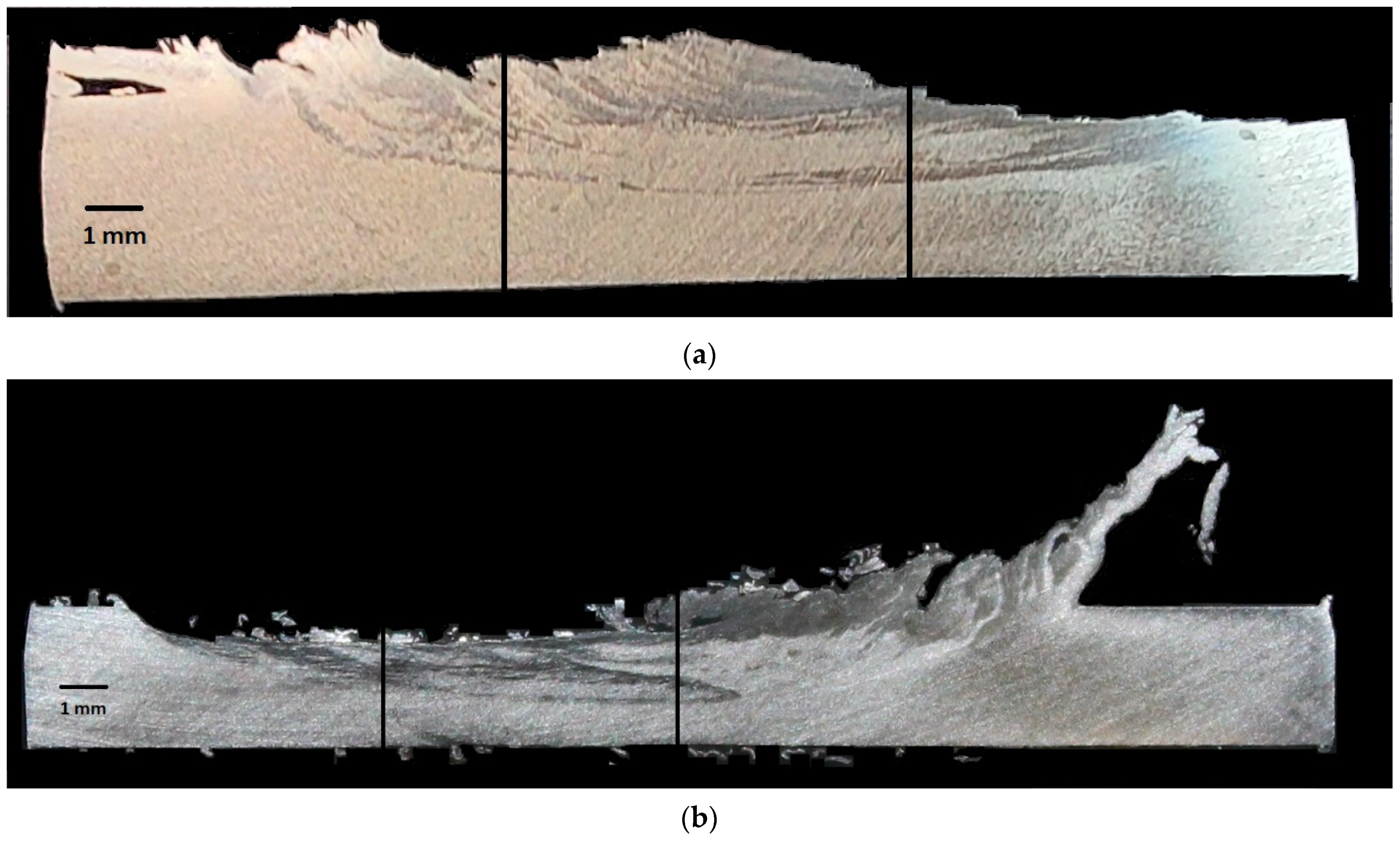
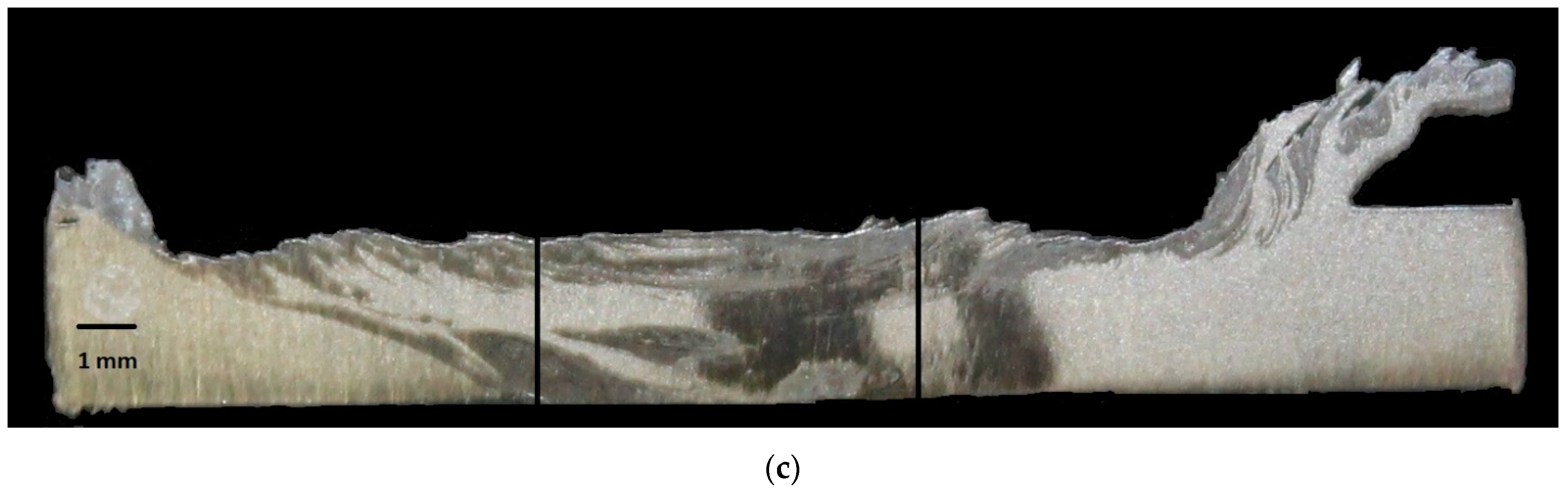
  • Optical microscopy revealed bright bands across the cross-section; the size and shape of these bands changed along the processed strip.
  • The microhardness values measured at the bright regions were significantly higher than those of the rest of the material subjected to FSP.
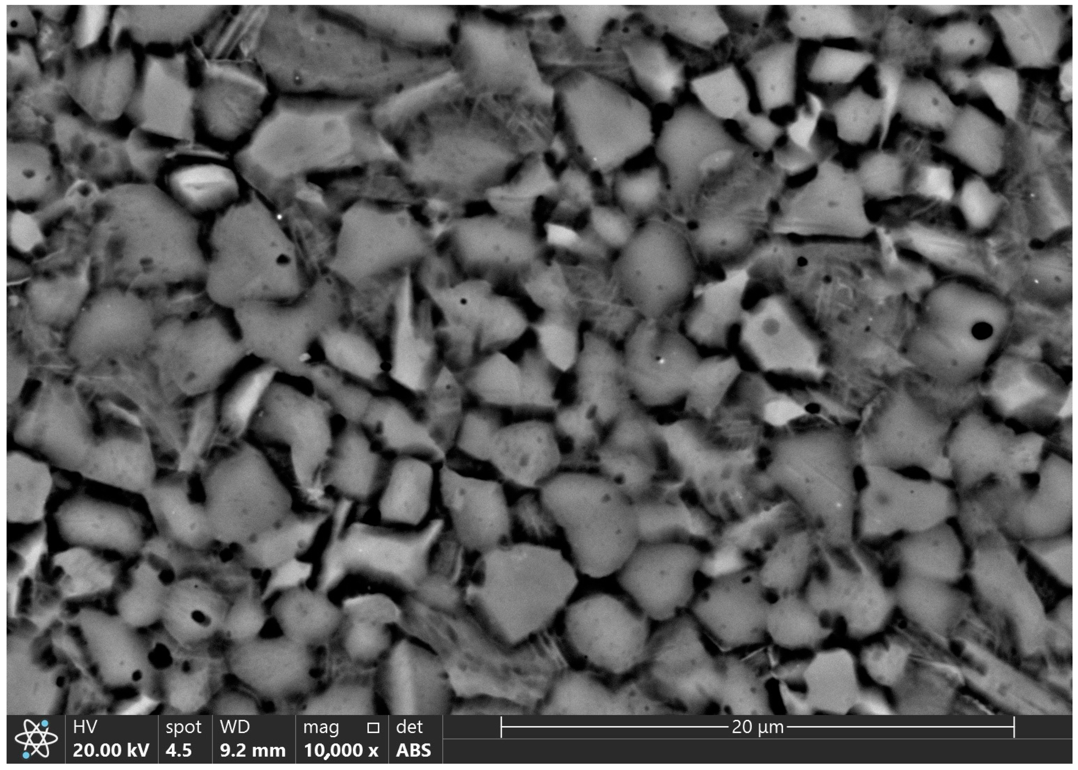
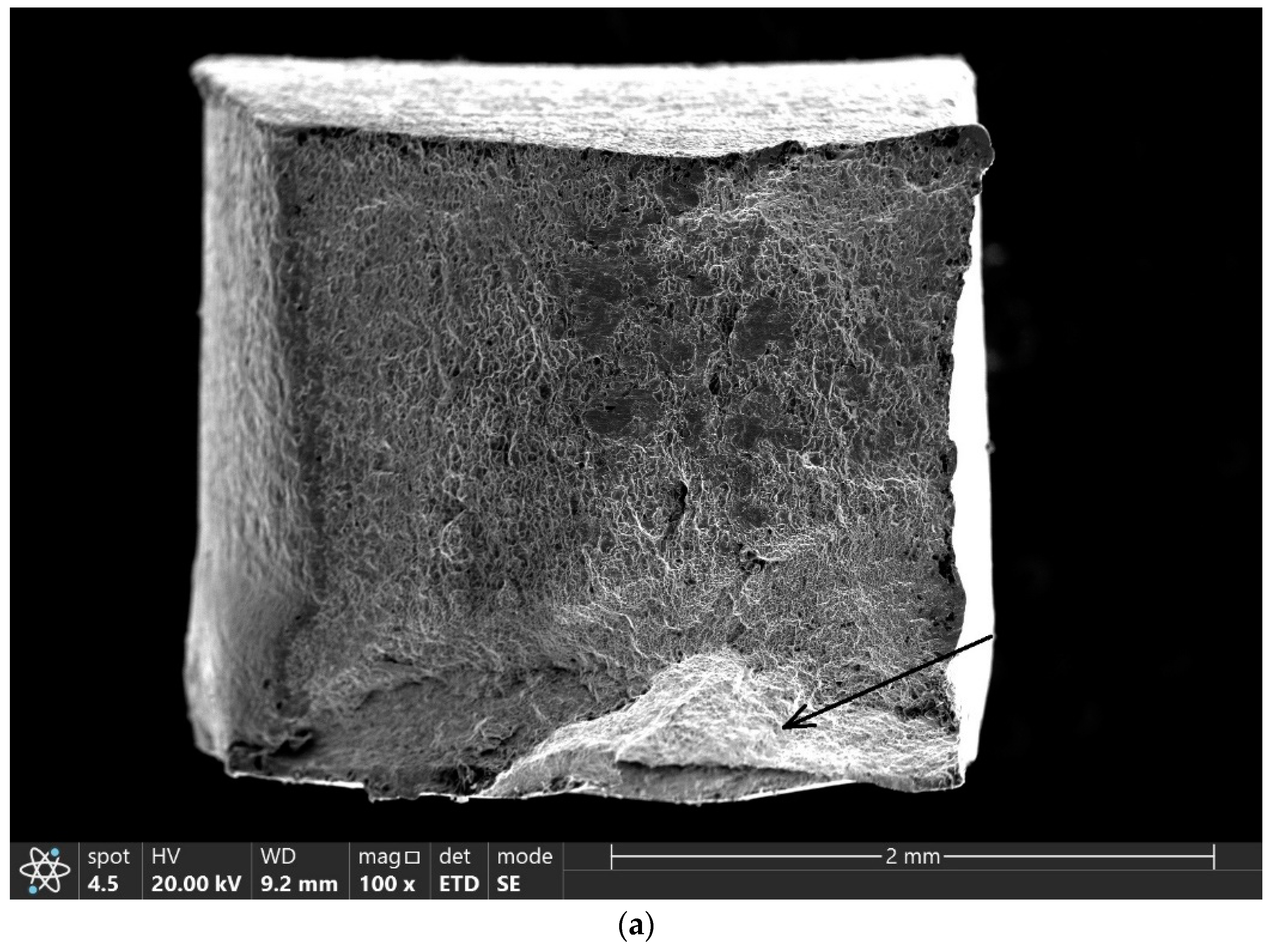
  • A SEM study showed that these regions were composed of fine equiaxed α grains having an average size of one to two microns, together with a retained β phase at the grain boundaries as well as separate β grains to a certain extent. These regions also served as fracture nucleation sites, as revealed by a fractography study.
  • EDS analyses conducted on the bright regions revealed that their chemical composition was similar to the rest of the stir zone, namely pure Ti.
  • The above regions are likely to be due to excessive DRX resulting from higher amounts of plastic deformation.
  • Due to its markedly lower cost than Ti alloys such as Ti-6Al-4V, CP-Ti subjected to FSP has the potential to become an industrial means of improving the mechanical properties of the material to make it a partial replacement for expensive alloys.
  • The material that underwent FSP showed improved mechanical properties at room temperature as expected, but the microstructure revealed in the deformation bands was not expected since it had not been reported before.
  • Further research is still required in order to find suitable processing parameters that can yield an entire cross-section having the microstructure of the deformation bands. These parameters include the rotational speed, transverse speed, shape and material of the processing tool. The stability of this microstructure upon exposure to high temperatures and its creep properties should be investigated as well.

Author Contributions

Conceptualization, M.R. and S.S.; data curation, M.R.; formal analysis, M.R. and S.S.; funding acquisition, M.R.; investigation, M.R. and S.S.; methodology, M.R. and S.S.; validation, S.S.; writing—original draft, M.R.; writing—review and editing, M.R. All authors have read and agreed to the published version of the manuscript.

Funding

This research project is partially funded by Braude College of Engineering.

Data Availability Statement

The data presented in this study are available on request from the corresponding author due to privacy.

Acknowledgments

The assistance of Netzer Navot in processing the material is highly appreciated. The authors thank A. Katz-Demyanetz and T. Vompe for their assistance with the SEM study. A special thanks also goes out to Shmuel Ariely for assisting with the EBSD analysis.

Conflicts of Interest

The authors declare no conflicts of interest.

References

  1. Zhang, Y.; Sato, Y.S.; Kokawa, H.; Park, S.H.C.; Hirano, S. Stir zone microstructure of commercial purity titanium friction stir welded using pcBN tool. Mater. Sci. Eng. A 2008, 488, 25–30. [Google Scholar] [CrossRef]
  2. Lee, W.B.; Lee, C.Y.; Chang, W.S.; Yeon, Y.M.; Jung, S.B. Microstructural investigation of friction stir welded pure titanium. Mater. Lett. 2005, 59, 3315–3318. [Google Scholar] [CrossRef]
  3. Reshad Seighalani, K.; Besharati Givi, M.K.; Nasiri, A.M.; Behemat, P. Investigations on the effects of the tool material, geometry, and tilt angle on friction stir welding of pure titanium. J. Mater. Eng. Perform. 2010, 19, 955–962. [Google Scholar] [CrossRef]
  4. Fujii, H.; Sun, Y.; Kato, H.; Nakata, K. Investigation of welding parameter dependent microstructure and mechanical properties in friction stir welded pure Ti joints. Mater. Sci. Eng. A 2010, 527, 3386–3391. [Google Scholar] [CrossRef]
  5. Kim, J.D.; Jin, E.G.; Murugan, S.P.; Park, Y.D. Recent advances in friction-stir welding process and microstructural investigation of friction stir welded pure titanium. J. Weld. Join. 2017, 35, 6–15. [Google Scholar] [CrossRef]
  6. Karna, S.; Cheepu, M.; Venkateswarulu, D.; Srikanth, V. Recent developments and research progress on friction stir welding of titanium alloys: An overview. IOP Conf. Ser. Mater. Sci. Eng. 2018, 330, 012068. [Google Scholar] [CrossRef]
  7. Xu, N.; Song, Q.; Bao, Y.; Jiang, Y.; Shen, J.; Cao, X. Twinning-induced mechanical properties’ modification of CP-Ti by friction stir welding associated with simultaneous backward cooling. Sci. Technol. Weld. Join. 2017, 7, 610–616. [Google Scholar] [CrossRef]
  8. Bahl, S.; Nithilaksh, P.L.; Suwas, S.; Kailas, S.V.; Chatterjee, K. Processing–microstructure–crystallographic texture–surface property relationships in friction stir processing of titanium. J. Mater. Eng. Perform. 2017, 26, 4206–4216. [Google Scholar] [CrossRef]
  9. Jiang, L.; Huang, W.; Liu, C.; Chai, L.; Yang, X.; Xu, Q. Microstructure, texture evolution and mechanical properties of pure Ti by friction stir processing with slow rotation speed. Mater. Charact. 2019, 148, 1–8. [Google Scholar] [CrossRef]
  10. Singh, A.K.; Kaushik, L.; Pawar, S.; Singh, J.; Das, H.; Mondal, M.; Hong, S.T.; Choi, S.H. Unraveling the heterogeneous evolution of the microstructure and texture in the thermomechanically affected zone of commercially pure titanium during friction stir processing. Int. J. Mech. Sci. 2023, 239, 107894. [Google Scholar] [CrossRef]
  11. Vakili-Azghandi, M.; Rokinan, M.; Szpunar, J.A.; Mousavizade, S.M. Surface modification of pure titanium via friction stir processing: Microstructure evolution and dry sliding wear performance. J. Alloys Compd. 2020, 816, 152557. [Google Scholar] [CrossRef]
  12. Fattah-alhosseini, A.; Vakili-Azghandi, M.; Haghshenas, M. On the passive and electrochemical behavior of severely deformed pure Ti through friction stir processing. Int. J. Adv. Manuf. Technol. 2017, 90, 991–1002. [Google Scholar] [CrossRef]
  13. Singh, A.K.; Kaushik, L.; Pawar, S.; Singh, J.; Das, H.; Mondal, M.; Hong, S.T.; Choi, S.H. Evolution of microstructure and texture in the stir zone of commercially pure titanium during friction stir processing. Int. J. Plast. 2022, 150, 103184. [Google Scholar] [CrossRef]
  14. Zhang, Y.; Sato, Y.S.; Kokawa, H.; Park, S.H.C.; Hirano, S. Grain structure and microtexture in friction stir welded commercial purity titanium. Sci. Technol. Weld. Join. 2010, 15, 500–505. [Google Scholar] [CrossRef]
  15. Nguyen, H.D.; Pramanik, A.; Basak, A.K.; Dong, Y.; Prakash, C.; Debnath, S.; Shankar, S.; Jawahir, I.S.; Dixit, S.; Buddhi, D. A Critical Review on Additive Manufacturing of Ti-6Al-4V Alloy: Microstructure and Mechanical Properties. J. Mater. Res. Technol. 2022, 18, 4641–4661. [Google Scholar] [CrossRef]
  16. Mishra, R.S.; Mahoney, M.W.; McFadden, S.X.; Mara, N.A.; Mukherjee, A.K. High strain rate superplasticity in a friction stir processed 7070 Al alloy. Scr. Mater. 2000, 42, 163–168. [Google Scholar] [CrossRef]
  17. Rubtsov, V.; Chumaevskii, A.; Knyazhev, E.; Utyaganova, V.; Gurianov, D.; Amirov, A.; Cheremnov, A.; Kolubaev, E. The Regularities of Metal Transfer by a Nickel-Based Superalloy Tool During Friction Stir Processing of a Titanium Alloy Produced by Wire-Feed Electron Beam Additive Manufacturing. Metals 2024, 14, 105. [Google Scholar] [CrossRef]
  18. Kang, D.S.; Lee, K.J. Recent R&D status on friction stir welding of Ti and its alloys. J. Weld. Join. 2015, 33, 1–7. [Google Scholar]
  19. Mironov, S.; Sato, Y.S.; Kokawa, H. Development of grain structure during friction stir welding of pure titanium. Acta Mater. 2009, 57, 4519–4528. [Google Scholar] [CrossRef]
  20. Liu, H.; Nakata, K.; Yamamoto, N.; Liao, J. Friction stir welding of pure titanium lap joint. Sci. Technol. Weld. Join. 2010, 15, 428–432. [Google Scholar] [CrossRef]
  21. Fonda, R.W.; Knipling, K.E.; Levinson, A.J.; Feng, C.R. Enhancing the weldability of CP titanium friction stir welds with elemental foils. Sci. Technol. Weld. Join. 2019, 24, 617–623. [Google Scholar] [CrossRef]
  22. Ganesan, R.; Porthur, H. Review on Friction Stir Welding of Titanium Alloys—A Fracture Mechanics Perspective. In Advances in Additive Manufacturing and Metal Joining, Proceedings of the AIMTDR, Virtual, 9–11 December 2021; Ramesh Babu, N., Kumar, N.S., Thyla, P.R., Sripriyan, K., Eds.; Springer Nature Singapore Pte Ltd.: Singapore, 2023; pp. 445–458. [Google Scholar]
  23. Chumaevskii, A.; Amirov, A.; Ivanov, A.; Rubtsov, V.; Kolubaev, E. Friction Stir Welding/Processing of Various Metals with Working Tools of Different Materials and Its Peculiarities for Titanium Alloys: A Review. Metals 2023, 13, 970. [Google Scholar] [CrossRef]
  24. Sajid, M.; Kumar, G.; Kumar, M. Recent advances in friction stir welding and processing of light metals alloys. Int. J. Res. Eng. Innov. 2023, 7, 15–22. [Google Scholar] [CrossRef]
  25. Vakili-Azghandi, M.; Hatami, F.M.; Szpunar, J.A. Mechanical properties and corrosion behavior of titanium surface biocomposites reinforced with Al2O3 particles fabricated by friction stir processing. Mater. Chem. Phys. 2024, 313, 128749. [Google Scholar] [CrossRef]
  26. Zykova, A.P.; Tarasov, S.Y.; Chumaevskiy, A.V.; Kolubaev, E.A. A Review of Friction Stir Processing of Structural Metallic Materials: Process, Properties, and Methods. Metals 2020, 10, 772. [Google Scholar] [CrossRef]
  27. Ding, Z.; Fan, Q.; Wang, L. A Review on Friction Stir Processing of Titanium Alloy: Characterization, Method, Microstructure. Metall. Mater. Trans. B 2019, 50B, 2134–2162. [Google Scholar] [CrossRef]
  28. Santhanam, S.K.V.; Jeyarajan, J.R.; Manivannan, S.K.; Jayamanickam, J.B.; Kuppusamy, R.; Nambi, N. Analysis on Mechanical Properties and Corrosion Behavior of Friction Stir Processing of Commercially Pure-Titanium. In Proceedings of the ASME 2022 International Mechanical Engineering Congress and Exposition, Columbus, OH, USA, 30 October–3 November 2022; American Society of Mechanical Engineers: New York, NY, USA, 2022. [Google Scholar]
  29. Regev, M.; Almoznino, B.; Spigarelli, S. A Study of the Metallurgical and Mechanical Properties of Friction-Stir-Welded Pure Titanium. Metals 2023, 13, 524. [Google Scholar] [CrossRef]
  30. Regev, M.; Spigarelli, S. Metallurgical and Mechanical Properties of Friction Stir-Welded Pure Titanium. J. Mater. Eng. Perform. 2024; published online. [Google Scholar] [CrossRef]
  31. Zheng Chen, G.; Fray, D.J.; Farthing, T.W. Cathodic Deoxygenation of the Alpha Case on Titanium and Alloys in Molten Calcium Chloride. Metall. Mater. Trans. 2001, 32B, 1041–1052. [Google Scholar] [CrossRef]
Figure 1. Tensile specimen (a) configuration within the processed plate; (b) a drawing.
Metals 14 00644 g001
Figure 2. Optical images of cross-sections taken along the processed strip (a) after the first third, (b) after the second third, (c) after the final third.
Metals 14 00644 g002aMetals 14 00644 g002b
Figure 3. Microhardness profiles of the cross-sections shown in Figure 2a–c taken at various depths: (a) after the first third; (b) after the second third; (c) after the final third.
Metals 14 00644 g003aMetals 14 00644 g003b
Figure 4. SEM image taken from one of the bright bands.
Metals 14 00644 g004
Figure 5. HRSEM EBSD taken from a bright band: (a) grain map image; (b) misorientation angle histogram; (c) grain size histogram; and (d) phase map image.
Metals 14 00644 g005aMetals 14 00644 g005b
Figure 6. SEM micrographs of the fracture surface of broken tensile specimens: (a) general view where the arrow points at the fracture origin; (b) fracture origin under high magnification.
Metals 14 00644 g006aMetals 14 00644 g006b
Table 1. Tensile test results.
TypeAverage Yield Strength [MPa]Yield Strength S.D. [MPa]Ultimate Tensile Strength [MPa]Ultimate Tensile Strength S.D. [MPa]Elongation [%]Elongation S.D. [%]
PM 325.4 27.4 504.6 10.8 37.6 4.8
Subjected to FSP481.841.3616.841.8 11.8 4.4
Disclaimer/Publisher’s Note: The statements, opinions and data contained in all publications are solely those of the individual author(s) and contributor(s) and not of MDPI and/or the editor(s). MDPI and/or the editor(s) disclaim responsibility for any injury to people or property resulting from any ideas, methods, instructions or products referred to in the content.

