
Interaction of Mechanical Characteristics in Workpiece Subsurface Layers with Drilling Process Energy Characteristics

Abstract
:1. Introduction
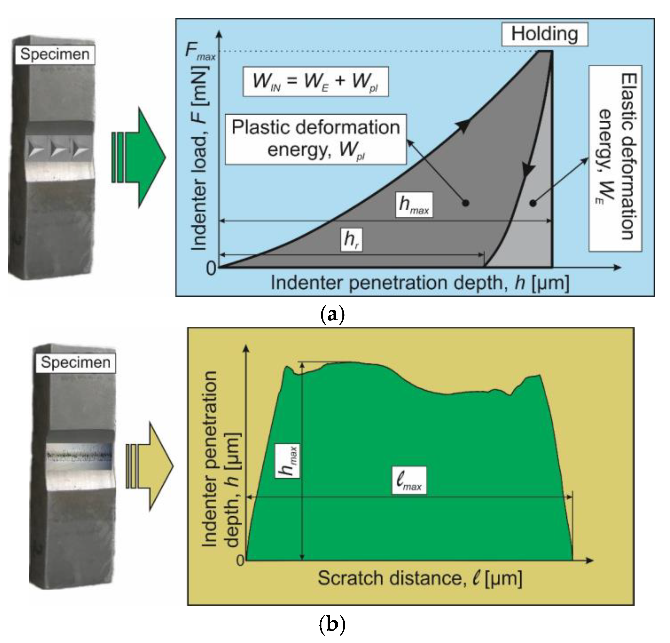
2. Mechanical Characteristics Determination of Drilled Subsurface Layers
3. Materials and Methods
3.1. Materials
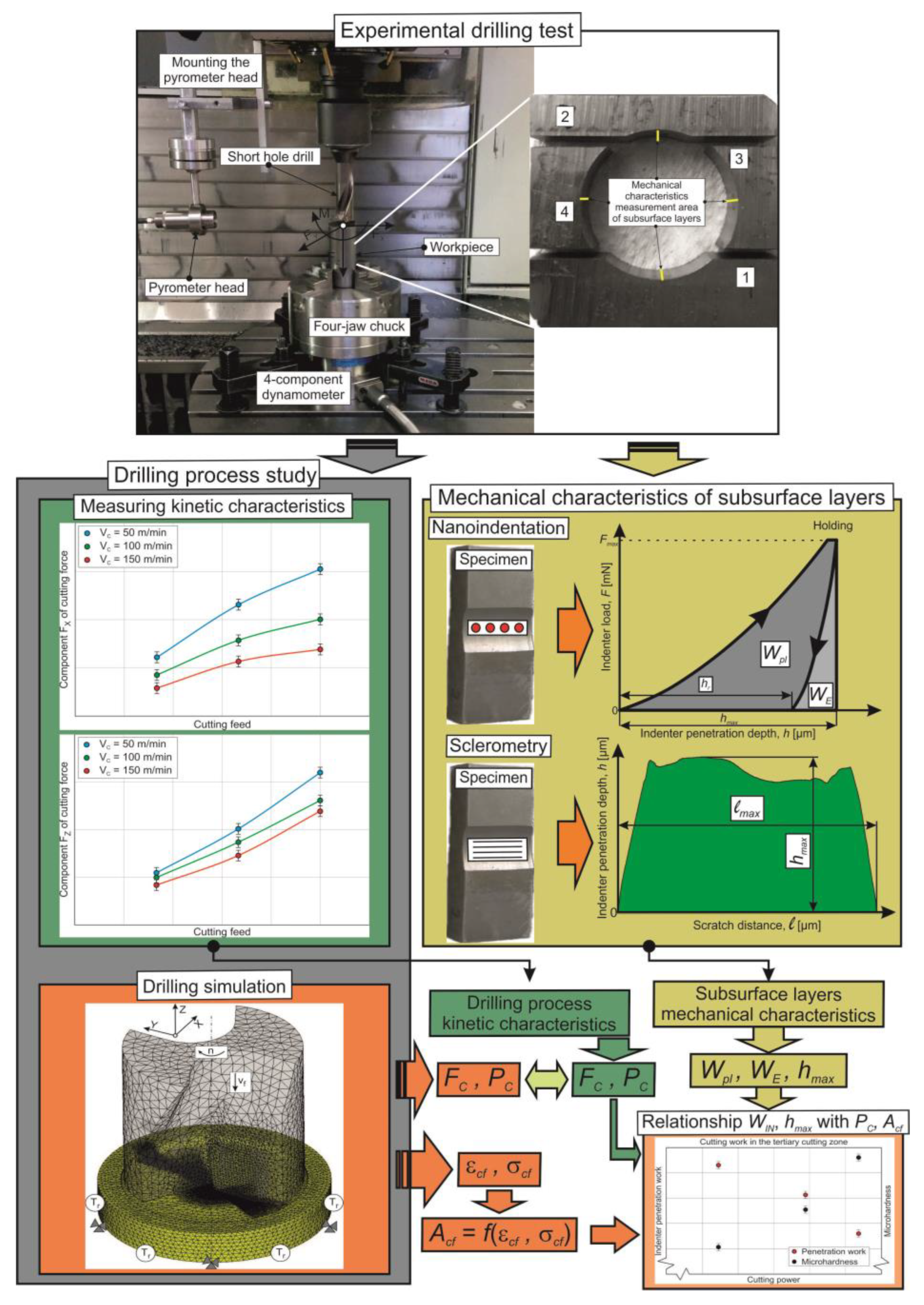
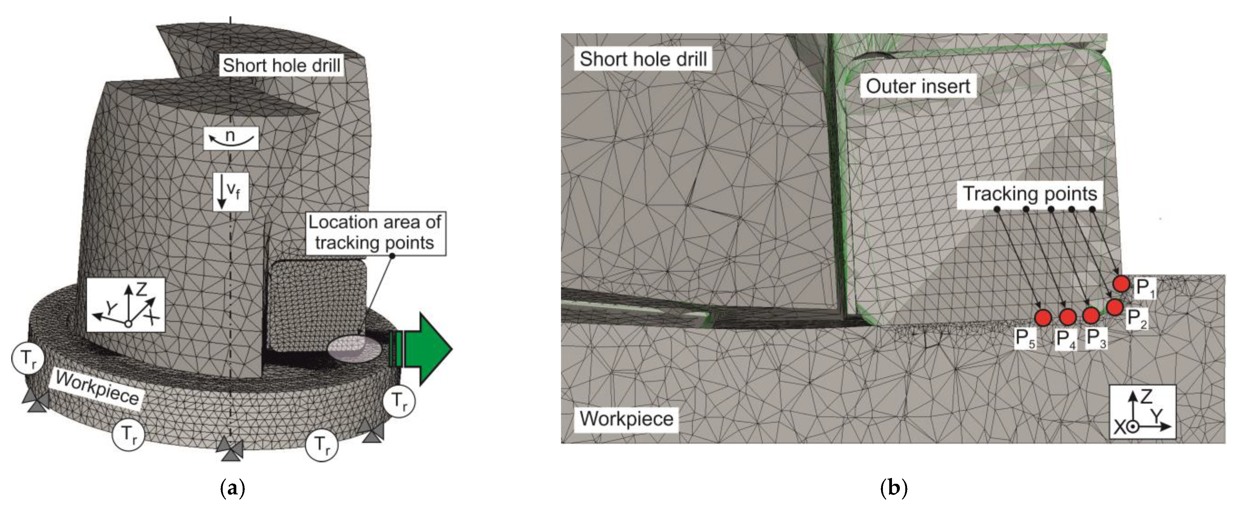
3.2. Methods
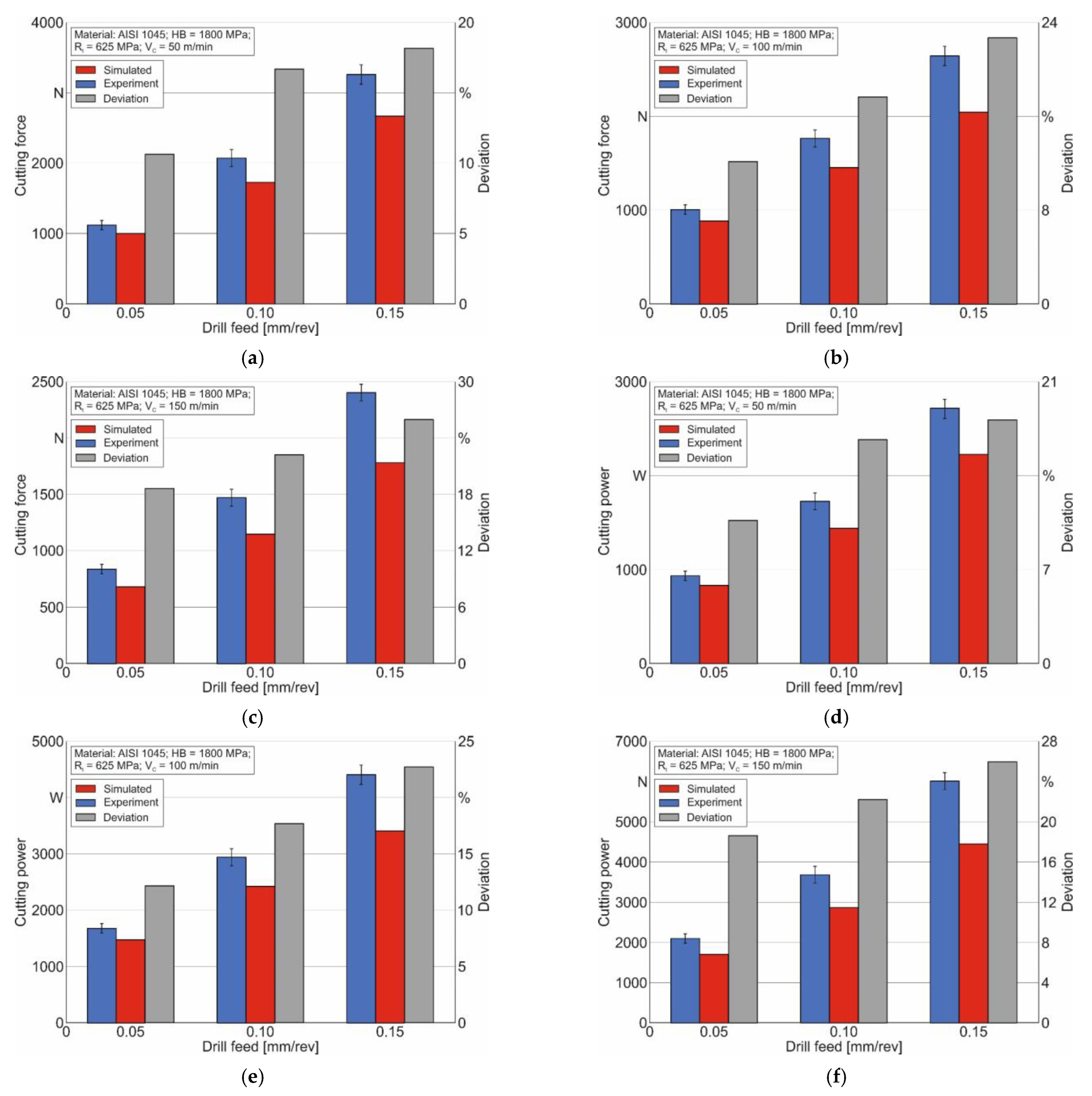
4. Results
5. Discussion
6. Conclusions
Author Contributions
Funding
Data Availability Statement
Acknowledgments
Conflicts of Interest
References
- Guo, Y.; Saldana, C.; Compton, W.D.; Chandrasekar, S. Controlling deformation and microstructure on machined surfaces. Acta Mater. 2011, 59, 4538–4547. [Google Scholar] [CrossRef]
- Sagapuram, D.; Udupa, A.; Viswanathan, K.; Mann, J.B.; M’Saoubi, R.; Sugihara, T.; Chandrasekar, S. On the Cutting of Metals: A Mechanics Viewpoint. ASME J. Manuf. Sci. Eng. 2020, 142, 110808. [Google Scholar] [CrossRef]
- Davim, J.P. Machining of Complex Sculptured Surfaces; Springer: London, UK, 2012; 258p. [Google Scholar] [CrossRef]
- Babichev, D.; Storchak, M. Synthesis of cylindrical gears with optimum rolling fatigue strength. Prod. Eng. Res. Dev. 2015, 9, 87–97. [Google Scholar] [CrossRef]
- Bag, R.; Panda, A.; Sahoo, A.K.; Kumar, R. A Perspective Review on Surface Integrity and Its Machining Behavior of AISI 4340 Hardened Alloy Steel. Mater. Today Proc. 2019, 18 Pt 7, 3532–3538. [Google Scholar] [CrossRef]
- Soori, M.; Arezoo, B. A Review in Machining-Induced Residual Stress. J. New Technol. Mater. 2022, 12, 64–83. Available online: https://hal.science/hal-03679993 (accessed on 19 April 2019).
- Malakizadi, A.; Bertolini, R.; Ducobu, F.; Kilic, Z.M.; Magnanini, M.C.; Shokrani, A. Recent advances in modelling and simulation of surface integrity in machining—A review. Procedia CIRP 2022, 115, 232–240. [Google Scholar] [CrossRef]
- Nagaraj, M.; Ezilarasan, C.; Kumar, A.J.P.; Velayudham, A. A review of machining characteristics in mechanical drilling of super alloy. Int. J. Mech. Prod. Eng. Res. Dev. 2018, 8, 579–588. [Google Scholar] [CrossRef]
- Kanaev, A.T.; Ramazanova, Z.M.; Biizhanov, S.K. Study of plasma-hardened wheel steel using nanoindentation. Industrial laboratory. Diagn. Mater. 2020, 86, 56–60. (In Russian) [Google Scholar] [CrossRef]
- Randall, N.X. The current state-of-the-art in scratch testing of coated systems. Surf. Coat. Technol. 2019, 380, 125092. [Google Scholar] [CrossRef]
- Storchak, M. Mechanical Characteristics Generation in the Workpiece Subsurface Layers through Cutting. Crystals 2023, 13, 761. [Google Scholar] [CrossRef]
- Komanduri, R. Machining and Grinding: A Historical Review of the Classical Papers. Appl. Mech. Rev. 1993, 46, 80–132. [Google Scholar] [CrossRef]
- Davim, J.P. Drilling Technology: Fundamentals and Recent Advances; De Gruyter Oldenbourg: Boston, MA, USA, 2018; 205p, ISBN 978-3110478631. [Google Scholar]
- Krishnaraj, V.; Zitoune, R.; Collombet, F. Comprehensive Review on Drilling of Multimaterial Stacks. J. Mach. Form. Technol. 2010, 2, 1–32. [Google Scholar]
- Kheireddine, A.H.; Ammouri, A.H.; Lu, T.; Jawahir, I.S.; Hamade, R.F. An FEM Analysis with Experimental Validation to Study the Hardness of In-Process Cryogenically Cooled Drilled Holes in Mg AZ31b. Procedia CIRP 2013, 8, 588–593. [Google Scholar] [CrossRef]
- Wegert, R.; Guski, V.; Schmauder, S.; Möhring, H.C. In-process approach for editing the subsurface properties during single-lip deep hole drilling using a sensor-integrated tool. Prod. Eng. Res. Dev. 2024, 18, 319–337. [Google Scholar] [CrossRef]
- Sun, Z.; Geng, D.; Guo, H.; Zhang, Q.; Liu, Y.; Liu, L.; Jiang, X.; Zhang, D. Introducing transversal vibration in twist drilling: Material removal mechanisms and surface integrity. J. Mater. Process. Technol. 2024, 325, 118296. [Google Scholar] [CrossRef]
- Strodick, S.; Schmidt, R.; Donnerbauer, K.; Rozo Vasquez, J.; Zabel, A.; Macias Barrientos, M.; Biermann, D.; Walther, F. Subsurface conditioning in BTA deep hole drilling for improved component performance. Prod. Eng. Res. Dev. 2024, 18, 299–317. [Google Scholar] [CrossRef]
- Ren, X.; Liu, Z. Influence of cutting parameters on work hardening behavior of surface layer during turning superalloy Inconel 718. Int. J. Adv. Manuf. Technol. 2016, 86, 2319–2327. [Google Scholar] [CrossRef]
- Garg, S.; Goyal, R.K. A Study of Surface Roughness in Drilling of AISI H11 Die Steel using Face Centered Design. Int. J. Innov. Res. Sci. Technol. 2015, 1, 464–474. [Google Scholar]
- Lacombe, A.; Landon, Y.; Paredes, M.; Chirol, C.; Benaben, A. Influence of the Hole Surface Integrity on the Fatigue Strength of an Aluminium Drilled Part. In Advances on Mechanics, Design Engineering and Manufacturing III. JCM 2020; Roucoules, L., Paredes, M., Eynard, B., Morer Camo, P., Rizzi, C., Eds.; Lecture Notes in Mechanical Engineering; Springer: Cham, Switzerland, 2020. [Google Scholar] [CrossRef]
- Farid, A.A.; Sharif, S.; Idris, M.H. Surface integrity study of high-speed drilling of Al–Si alloy using HSS drill. Proc. Inst. Mech. Eng. Part B J. Eng. Manuf. 2011, 225, 1001–1007. [Google Scholar] [CrossRef]
- Barik, T.; Pal, K.; Parimita, S.; Sahoo, P.; Patra, K. Monitoring of hole surface integrity in drilling of bi-directional woven carbon fiber reinforced plastic composites. Proc. Inst. Mech. Eng. Part C J. Mech. Eng. Sci. 2020, 234, 2432–2458. [Google Scholar] [CrossRef]
- Mendas, M.; Benayoun, S.; Miloud, M.H.; Zidane, I. Microhardness model based on geometrically necessary dislocations for heterogeneous material. J. Mater. Res. Technol. 2021, 15, 2792–2801. [Google Scholar] [CrossRef]
- Ameri, A.A.H.; Elewa, N.N.; Ashraf, M.; Escobedo-Diaz, J.P. General methodology to estimate the dislocation density from microhardness measurements. Mater. Charact. 2017, 131, 324–330. [Google Scholar] [CrossRef]
- Varote, N.; Joshi, S.S. Microstructural Analysis of Machined Surface Integrity in Drilling a Titanium Alloy. J. Mater. Eng. Perform. 2017, 26, 4391–4401. [Google Scholar] [CrossRef]
- Haddag, B.; Yameogo, D.; Nouari, M.; Makich, H. Multi-Physics Analysis of Machining Ti-6Al-4V Alloy: Experimental Characterization and a New Material Behavior Modeling. Metals 2022, 12, 581. [Google Scholar] [CrossRef]
- Wang, Z.-Y.; Ren, J.-X.; Zhou, J.-H.; Cai, J. Correlation analysis of microstructure evolution on microhardness and residual stress for cutting Ti-6Al-4V titanium alloy. Proc. Inst. Mech. Eng. Part B J. Eng. Manuf. 2023, 237, 885–898. [Google Scholar] [CrossRef]
- Harun, S.; Burhanuddin, Y.; Ibrahim, G.A. The Effect of Cutting Parameters on Surface Roughness and Morphology of Ti-6Al-4V ELI Titanium Alloy during Turning with Actively Driven Rotary Tools. J. Manuf. Mater. Process. 2022, 6, 105. [Google Scholar] [CrossRef]
- Hussein, R.; Sadek, A.; Elbestawi, M.A.; Attia, M.H. Surface and microstructure characterization of low-frequency vibration-assisted drilling of Ti6Al4V. Int. J. Adv. Manuf. Technol. 2019, 103, 1443–1457. [Google Scholar] [CrossRef]
- Hou, G.; Li, A. Effect of Surface Micro-Hardness Change in Multistep Machining on Friction and Wear Characteristics of Titanium Alloy. Appl. Sci. 2021, 11, 7471. [Google Scholar] [CrossRef]
- Rangasamy, N.; Rakurty, C.S.; Balaji, A.K. A Multiscale Study on Machining Induced Surface Integrity in Ti-6Al-4V Alloy. Procedia CIRP 2022, 108, 787–792. [Google Scholar] [CrossRef]
- Rodriguez, I.; Arrazola, P.J.; Cuesta, M.; Sterle, L.; Pušavec, F. Improving surface integrity when drilling CFRPs and Ti-6Al-4V using sustainable lubricated liquid carbon dioxide. Chin. J. Aeronaut. 2023, 36, 129–146. [Google Scholar] [CrossRef]
- Murad, M.N.; Sharif, S.; Rahim, E.A.; Rival, R. Effect of Drill Point Angle on Surface Integrity when Drilling Titanium Alloy. In Adv. Mater. Res. 2013, 845, 966–970. [Google Scholar] [CrossRef]
- Lotfi, M.; Farid, A.A.; Akbari, J.; Sharif, S.; Mohruni, A.S. Evaluation of surface integrity when drilling Inconel 718 through experimental measurement and finite element analysis. Int. J. Adv. Manuf. Technol. 2022, 119, 4237–4248. [Google Scholar] [CrossRef]
- Dutilh, V.; Dessein, G.; Alexis, J.; Perrin, G. Links Between Machining Parameters and Surface Integrity in Drilling Ni-Superalloy. Adv. Mater. Res. 2010, 112, 171–178. [Google Scholar] [CrossRef]
- Xu, D.; Ding, L.; Liu, Y.; Zhou, J.; Liao, Z. Investigation of the Influence of Tool Rake Angles on Machining of Inconel 718. J. Manuf. Mater. Process. 2021, 5, 100. [Google Scholar] [CrossRef]
- Rahim, E.A.; Sasahara, H. An Analysis of Surface Integrity when Drilling Inconel 718 Using Palm Oil and Synthetic Ester under MQL Condition. Mach. Sci. Technol. 2011, 15, 76–90. [Google Scholar] [CrossRef]
- Karabulut, Y.; Kaynak, Y. Drilling process and resulting surface properties of Inconel 718 alloy fabricated by Selective Laser Melting Additive Manufacturing. Procedia CIRP 2020, 87, 355–359. [Google Scholar] [CrossRef]
- Girinon, M.; Valiorgue, F.; Rech, J.; Feulvarch, E. Development of a Procedure to Characterize Residual Stresses Induced by Drilling. Procedia CIRP 2016, 45, 79–82. [Google Scholar] [CrossRef]
- Nobre, J.P.; Outeiro, J.C. Evaluating Residual Stresses Induced by Drilling of Ti-6Al-4V Alloy by Using an Experimental-numerical Methodology. Procedia CIRP 2015, 31, 215–220. [Google Scholar] [CrossRef]
- Rasti, A.; Sadeghi, M.H.; Farshi, S.S. An analytical study on residual stresses in drilling of hardened steel. Int. J. Adv. Manuf. Technol. 2018, 99, 2389–2405. [Google Scholar] [CrossRef]
- Leveille, T.; Valiorgue, F.; Dumas, M.; Masciantonio, U.; Brosse, A.; Karaouni, H.; Rech, J. 3D numerical modelling of residual stresses induced by reaming. J. Manuf. Process. 2024, 113, 47–60. [Google Scholar] [CrossRef]
- Wu, R.; Huang, S.; Zhang, W.; Zhu, M.; Zheng, Z.; Li, T.; Xue, H. An improved grey wolf optimizer for minimizing drilling deformation and residual stress in AA2024 sheet. Int. J. Adv. Manuf. Technol. 2024, 130, 4443–4458. [Google Scholar] [CrossRef]
- Pharr, G.M. Recent advances in small-scale mechanical property measurement by nanoindentation. Curr. Opin. Solid State Mater. Sci. 2015, 19, 315–316. [Google Scholar] [CrossRef]
- Fischer-Cripps, A.C. Critical review of analysis and interpretation of nanoindentation test data. Surf. Coat. Technol. 2006, 200, 4153–4165. [Google Scholar] [CrossRef]
- Wredenberg, F.; Larsson, P.-L. Scratch testing of metals and polymers: Experiments and numerics. Wear 2009, 266, 76–83. [Google Scholar] [CrossRef]
- Kolawole, O.; Ispas, I. Evaluation of geomechanical properties via scratch tests: Where are we and where do we go from here? SN Appl. Sci. 2020, 2, 1633. [Google Scholar] [CrossRef]
- Fischer-Cripps, A.C. Nanoindentation, 2nd ed.; Springer: Berlin/Heidelberg, Germany, 2011; 276p. [Google Scholar] [CrossRef]
- Atkins, A.G.; Tabor, D. Plastic Indentation in Metals with Cones. J. Mech. Phys. Solids 1965, 13, 149–164. [Google Scholar] [CrossRef]
- Doerner, M.; Nix, W. A method for interpreting the data from depth-sensing indentation instruments. J. Mater. Res. 1986, 1, 601–609. [Google Scholar] [CrossRef]
- Oliver, W.C.; Pharr, G.M. An improved technique for determining hardness and elastic modulus using load and displacement sensing indentation experiments. J. Mater. Res. 1992, 7, 1564–1583. [Google Scholar] [CrossRef]
- Zivic, F.; Babic, M.; Adamovic, D.; Mitrovic, S.; Todorovic, P.; Favaro, G.; Pantić, M. Influence of the surface roughness on adhesion of chrome coatings on alloy tool steel x165crmov12. J. Balk. Tribol. Assoc. 2012, 18, 228–237. [Google Scholar]
- Bull, S.J. Failure modes in scratch adhesion testing. Surf. Coat. Technol. 1991, 50, 25–32. [Google Scholar] [CrossRef]
- Lin, C.K.; Berndt, C.C. Measurement and analysis of adhesion strength for thermally sprayed coatings. J. Therm. Spray Technol. 1994, 3, 75–104. [Google Scholar] [CrossRef]
- Yildiz, F.; Asaran, A. Multi-pass scratch test behavior of modified layer formed during plasma nitriding. Tribol. Int. 2010, 43, 1472–1478. [Google Scholar] [CrossRef]
- Storchak, M.; Zakiev, I.; Träris, L. Mechanical properties of subsurface layers in the machining of the titanium alloy Ti10V2Fe3Al. J. Mech. Sci. Technol. 2018, 32, 315–322. [Google Scholar] [CrossRef]
- Sousa, F.J.P.; Tridapalli, D.; Pereira, M.; Flesch, C.A.; Alarcon, O.E. Evaluation of measurement uncertainties for a scratching tester. Measurement 2006, 39, 594–604. [Google Scholar] [CrossRef]
- Fritz, R.; Kiener, D. Development and application of a heated in-situ SEM micro-testing device. Measurement 2017, 110, 356–366. [Google Scholar] [CrossRef]
- Sivaram, S.; Jayasinghe, J.A.S.C.; Bandara, C.S. Qualitative Study on Pile-up Effect on Hardness Test by Nano-Indentation. Eng. J. Inst. Eng. 2021, 54, 47–55. [Google Scholar] [CrossRef]
- Farayibi, P.K.; Hankel, J.; van gen Hassend, F.; Blüm, M.; Weber, S.; Röttger, A. Tribological characteristics of sintered martensitic stainless steels by nano-scratch and nanoindentation tests. Wear 2023, 512–513, 204547. [Google Scholar] [CrossRef]
- Li, Z.; Herrmann, K.; Pohlenz, F. A comparative approach for calibration of the depth measuring system in a nanoindentation instrument. Measurement 2006, 39, 547–552. [Google Scholar] [CrossRef]
- Peng, G.; Xu, F.; Chen, J.; Hu, Y.; Wang, H.; Zhang, T. A cost-effective voice coil motor-based portable micro-indentation device for in situ testing. Measurement 2020, 165, 108105. [Google Scholar] [CrossRef]
- Ding, K.; Zhang, Y.; Birnbaum, A.J.; Michopoulos, J.G.; McDowell, D.L.; Zhu, T. Strain gradient plasticity modeling of nanoindentation of additively manufactured stainless steel. Extrem. Mech. Lett. 2021, 49, 101503. [Google Scholar] [CrossRef]
- Vargas, A.L.M.; Blando, E.; Hübler, R. Elasto—Plastic materials behavior evaluation according to different models applied in indentation hardness tests. Measurement 2019, 139, 134–139. [Google Scholar] [CrossRef]
- Kang, J.J.; Becker, A.A.; Wen, W.; Sun, W. Extracting elastic-plastic properties from experimental loading-unloading indentation curves using different optimization techniques. Int. J. Mech. Sci. 2018, 144, 102–109. [Google Scholar] [CrossRef]
- Tsybenko, H.; Farzam, F.; Dehm, G.; Brinckmann, S. Scratch hardness at a small scale: Experimental methods and correlation to nanoindentation hardness. Tribol. Int. 2021, 163, 107168. [Google Scholar] [CrossRef]
- England, J.; Uddin, M.J.; Ramirez-Cedillo, E.; Karunarathne, D.; Nasrazadani, S.; Golden, T.D.; Siller, H.R. Nanoindentation Hardness and Corrosion Studies of Additively Manufactured 316L Stainless Steel. J. Mater. Eng. Perform. 2022, 31, 6795–6805. [Google Scholar] [CrossRef]
- Moon, J.; Kim, S.; Jang, J.; Lee, J.; Lee, C. Orowan strengthening effect on the nanoindentation hardness of the ferrite matrix in microalloyed steels. Mater. Sci. Eng. A 2008, 487, 552–557. [Google Scholar] [CrossRef]
- Li, C.; Zhao, H.; Sun, L.; Yu, X. In situ nanoindentation method for characterizing tensile properties of AISI 1045 steel based on mesomechanical analysis. Adv. Mech. Eng. 2019, 11, 1687814019862919. [Google Scholar] [CrossRef]
- Paul, V.; Ameyama, K.; Ota-Kawabata, M.; Ohmura, T. Evaluation of Deformation and Fracture Behavior in 304L Austenitic Steel Harmonic Structures through Nanoindentation. Steel Res. Int. 2023, 94, 2200354. [Google Scholar] [CrossRef]
- Zhou, G.; Guo, J.; Zhao, J.; Tang, Q.; Hu, Z. Nanoindentation Properties of 18CrNiMo7-6 Steel after Carburizing and Quenching Determined by Continuous Stiffness Measurement Method. Metals 2020, 10, 125. [Google Scholar] [CrossRef]
- Dean, J.; Aldrich-Smith, G.; Clyne, T.W. Use of nanoindentation to measure residual stresses in surface layers. Acta Mater. 2011, 59, 2749–2761. [Google Scholar] [CrossRef]
- Wang, H.; Zhu, L.; Xu, B. Residual Stresses and Nanoindentation Testing of Films and Coatings; Springer Nature Singapore Pte Ltd.: Singapore; Science Press: Beijing, China, 2018; 207p, ISBN 978-981-10-7840-8. [Google Scholar] [CrossRef]
- Zhang, W.; Wang, X.; Hu, Y.; Wang, S. Predictive modelling of microstructure changes, micro-hardness and residual stress in machining of 304 austenitic stainless steel. Int. J. Mach. Tools Manuf. 2018, 130–131, 36–48. [Google Scholar] [CrossRef]
- Fan, P.; Katiyar, N.K.; Zhou, X.; Goel, S. Uniaxial pulling and nano-scratching of a newly synthesised high entropy alloy. APL Mater. 2022, 10, 111118. [Google Scholar] [CrossRef]
- Pratap, A.; Divse, V.; Goel, S.; Joshi, S.S. Understanding the surface generation mechanism during micro-scratching of Ti-6Al-4V. J. Manuf. Process. 2022, 82, 543–558. [Google Scholar] [CrossRef]
- Liu, H.; Xu, X.; Zhang, J.; Liu, Z.; He, Y.; Zhao, W.; Liu, Z. The state of the art for numerical simulations of the effect of the microstructure and its evolution in the metal-cutting processes. Int. J. Mach. Tools Manuf. 2022, 177, 103890. [Google Scholar] [CrossRef]
- Bezyazychnyy, V.F.; Prokofev, M.A.; Vinogradova, N.V. Research of the Influence of Technological Machining Conditions on the Accumulation of Latent Energy Deformation in the surface Parts. Bull. PNIPU Aerosp. Eng. 2015, 43, 131–144. [Google Scholar] [CrossRef]
- Yamamoto, M.; Tanaka, M.; Furukimi, O. Hardness–Deformation Energy Relationship in Metals and Alloys: A Comparative Evaluation Based on Nanoindentation Testing and Thermodynamic Consideration. Materials 2021, 14, 7217. [Google Scholar] [CrossRef] [PubMed]
- Storchak, M.; Stehle, T.; Möhring, H.-C. Numerical Modeling of Cutting Characteristics during Short Hole Drilling: Modeling of Kinetic Characteristics. J. Manuf. Mater. Process. 2023, 7, 195. [Google Scholar] [CrossRef]
- Material Property Data. Available online: http://www.matweb.com (accessed on 19 April 2019).
- Storchak, M.; Stehle, T.; Möhring, H.-C. Determination of thermal material properties for the numerical simulation of cutting processes. Int. J. Adv. Manuf. 2021, 118, 1941–1956. [Google Scholar] [CrossRef]
- Oxley, P.L.B. Development and Application of a Predictive Machining Theory. Mach. Sci. Technol. 1998, 2, 165–189. [Google Scholar] [CrossRef]
- Heisel, U.; Kushner, V.; Storchak, M. Effect of machining conditions on specific tangential forces. Prod. Eng. 2012, 6, 621–629. [Google Scholar] [CrossRef]
- Tsekhanov, J.; Storchak, M. Development of analytical model for orthogonal cutting. Prod. Eng. Res. Dev. 2015, 9, 247–255. [Google Scholar] [CrossRef]
- Heisel, U.; Krivoruchko, D.V.; Zaloha, W.A.; Storchak, M.; Stehle, T. Thermomechanical material models in the modeling of cutting processes. ZWF Z. Fuer Wirtsch. Fabr. 2009, 104, 482–491. [Google Scholar] [CrossRef]
- Storchak, M.; Jiang, L.; Xu, Y.; Li, X. Finite element modeling for the cutting process of the titanium alloy Ti10V2Fe3Al. Prod. Eng. Res. Dev. 2016, 10, 509–517. [Google Scholar] [CrossRef]
- Johnson, G.R.; Cook, W.H. A constitutive model and data for metals subjected to large strains, high strain and high temperatures. In Proceedings of the 7th International Symposium on Ballistics, The Hague, The Netherlands, 19–21 April 1983; pp. 541–547. [Google Scholar]
- Heisel, U.; Krivoruchko, D.V.; Zaloha, W.A.; Storchak, M.; Stehle, T. Thermomechanical exchange effects in machining. ZWF Z. Fuer Wirtsch. Fabr. 2009, 104, 263–272. [Google Scholar] [CrossRef]
- Storchak, M.; Möhring, H.-C.; Stehle, T. Improving the friction model for the simulation of cutting processes. Tribol. Int. 2022, 167, 107376. [Google Scholar] [CrossRef]
- Fluhrer, J. Deform-User Manual Deform V12.0; SFTC: Columbus, OH, USA, 2019. [Google Scholar]
- Heisel, U.; Krivoruchko, D.V.; Zaloha, W.A.; Storchak, M.; Stehle, T. Breakage models for the modeling of cutting processes. ZWF Z. Fuer Wirtsch. Fabr. 2009, 104, 330–339. [Google Scholar] [CrossRef]
- Storchak, M.; Kushner, V.; Möhring, H.-C.; Stehle, T. Refinement of temperature determination in cutting zones. J. Mech. Sci. Technol. 2021, 35, 3659–3673. [Google Scholar] [CrossRef]
- Kushner, V.; Storchak, M. Determining mechanical characteristics of material resistance to deformation in machining. Prod. Eng. Res. Dev. 2014, 8, 679–688. [Google Scholar] [CrossRef]
- Kushner, V.; Storchak, M. Determination of Material Resistance Characteristics in Cutting. Procedia CIRP 2017, 58, 293–298. [Google Scholar] [CrossRef]
- Heisel, U.; Storchak, M.; Krivoruchko, D.V. Thermal effects in orthogonal cutting. Prod. Eng. Res. Dev. 2013, 7, 203–211. [Google Scholar] [CrossRef]


| Material | Strength (MPa) | Elastic Modulus (GPa) | Elongation (%) | Hard-ness | Poisson′s Ratio | Specific Heat (J/kg·K) | Thermal Expansion (µm/m·°C) | Thermal Conductivity (W/m·K) | |
|---|---|---|---|---|---|---|---|---|---|
| Tensile | Yield | ||||||||
| AISI 1045 | 690 | 620 | 206 | 12 | HB 180 | 0.29 | 486 | 14 | 49.8 |
Disclaimer/Publisher’s Note: The statements, opinions and data contained in all publications are solely those of the individual author(s) and contributor(s) and not of MDPI and/or the editor(s). MDPI and/or the editor(s) disclaim responsibility for any injury to people or property resulting from any ideas, methods, instructions or products referred to in the content. |
© 2024 by the authors. Licensee MDPI, Basel, Switzerland. This article is an open access article distributed under the terms and conditions of the Creative Commons Attribution (CC BY) license (https://creativecommons.org/licenses/by/4.0/).
Share and Cite
Storchak, M.; Hlembotska, L.; Melnyk, O.; Baranivska, N. Interaction of Mechanical Characteristics in Workpiece Subsurface Layers with Drilling Process Energy Characteristics. Metals 2024, 14, 683. https://doi.org/10.3390/met14060683
Storchak M, Hlembotska L, Melnyk O, Baranivska N. Interaction of Mechanical Characteristics in Workpiece Subsurface Layers with Drilling Process Energy Characteristics. Metals. 2024; 14(6):683. https://doi.org/10.3390/met14060683
Chicago/Turabian StyleStorchak, Michael, Larysa Hlembotska, Oleksandr Melnyk, and Nataliia Baranivska. 2024. "Interaction of Mechanical Characteristics in Workpiece Subsurface Layers with Drilling Process Energy Characteristics" Metals 14, no. 6: 683. https://doi.org/10.3390/met14060683