
The Effect of Energy Parameters of Power Sources on the Structure and Properties of Permanent Joints at Manual Arc Welding

Abstract
:1. Introduction
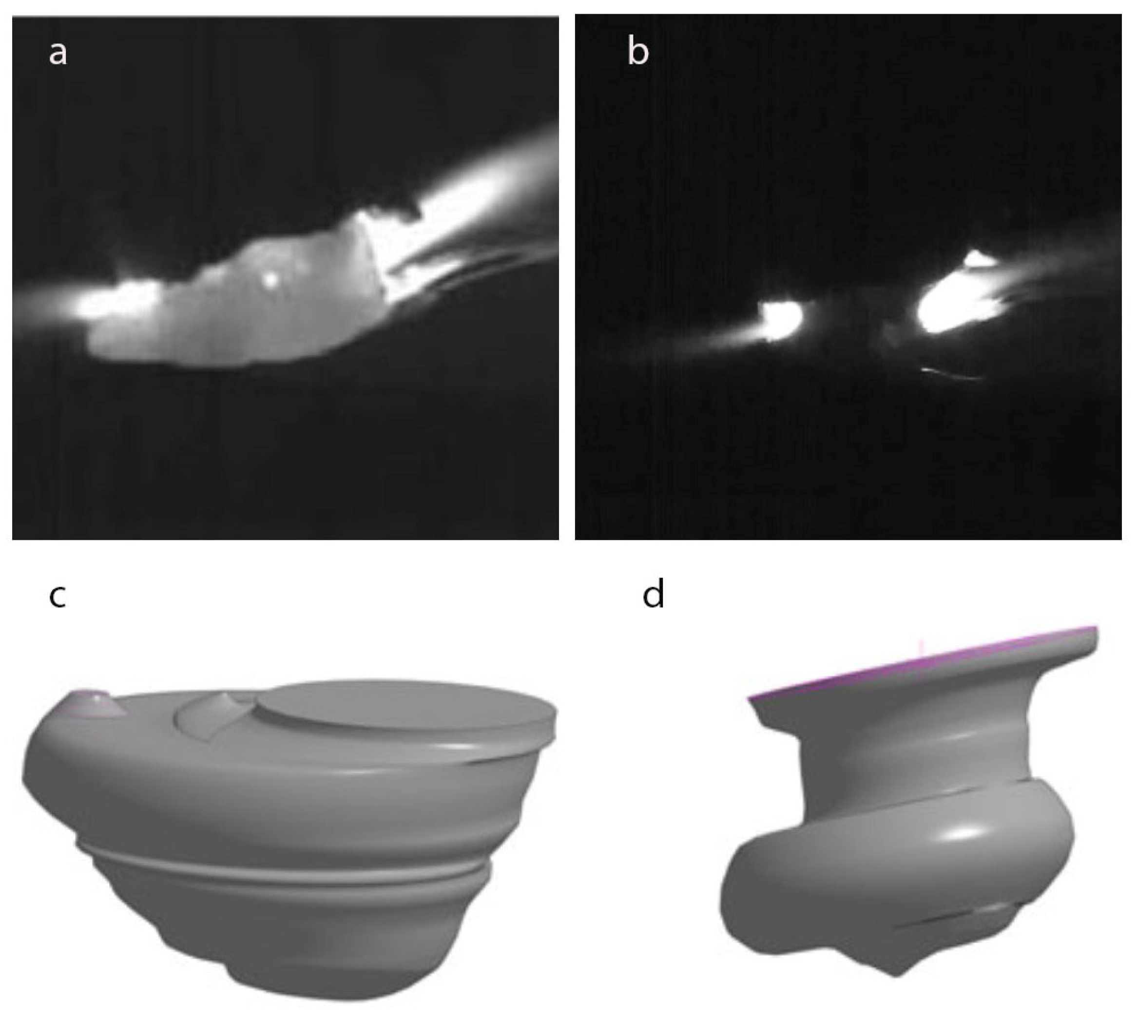
- The majority of the metal, approximately 85% [2], is transferred in the form of droplets;
- The size and shape of the droplets, as well as the frequency of their transfer, depend on the thermophysical properties of the electrode metal, the composition of the coating, the thickness of the coating, the diameter of the electrode, the welding regime, the polarity, and the relationship of forces acting on the molten electrode metal at various stages of melting and transfer.
- Higher rates of seam metal cooling and crystallization;
- Phase transformations of the base metal in the heat-affected zone.
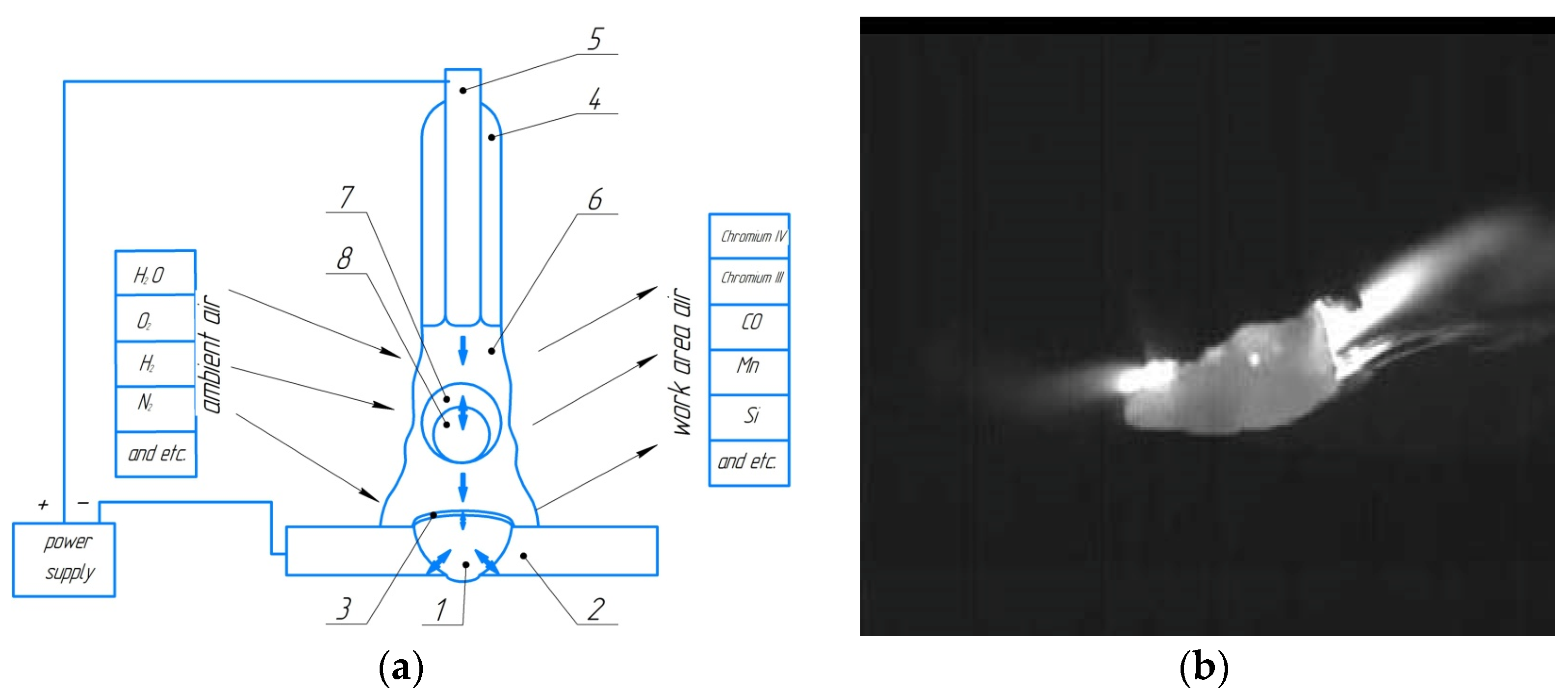
- The small volume of the weld pool and the relatively large number of reactive phases present within it;
- High temperatures within the welding arc (up to 7000 °C) leading to overheating of the molten material within the pool;
- The movement of liquid metal, intense mixing of molten materials, and continuous flow of metallurgical processes within the pool;
- Rapid cooling and solidification rates of deposited metal.
2. Methodology
- A pipe of steel 09G2S (joint type C17) with dimensions of 159 × 6 mm was welded with the following parameters: root pass was conducted with LB-52U (d = 2.6 mm) electrode at a welding current of 50–60 A; filling was conducted with LB-52U (d = 3.2 mm) electrode at a welding current of 80–90 A.
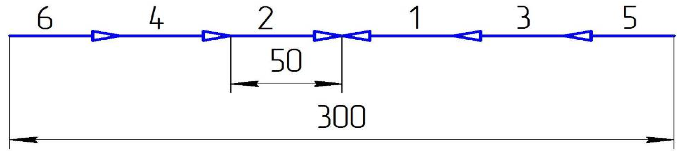
- Welding of 10 mm-thick plates made of steel 45 (joint type C17) was carried out using the following welding technique (Figure 3): the welding was performed in four layers with electrodes. The root pass was conducted with UONI 13/55 electrodes (d = 3 mm) at a welding current of 80–90 A. The filling was conducted with UONI 13/55 electrodes (d = 4 mm) at a welding current of 120–130 A. Before welding, the parts were preheated to 300 °C and then slowly cooled with asbestos fiber insulation until they were completely cooled.
- Welding of 3 mm-thick plates made of 12H18N10T steel (joint type C7) was carried out with CL11 electrodes of 08H20N9G2B type (d = 3 mm) at a welding current of 70–80 A.
3. Research Results
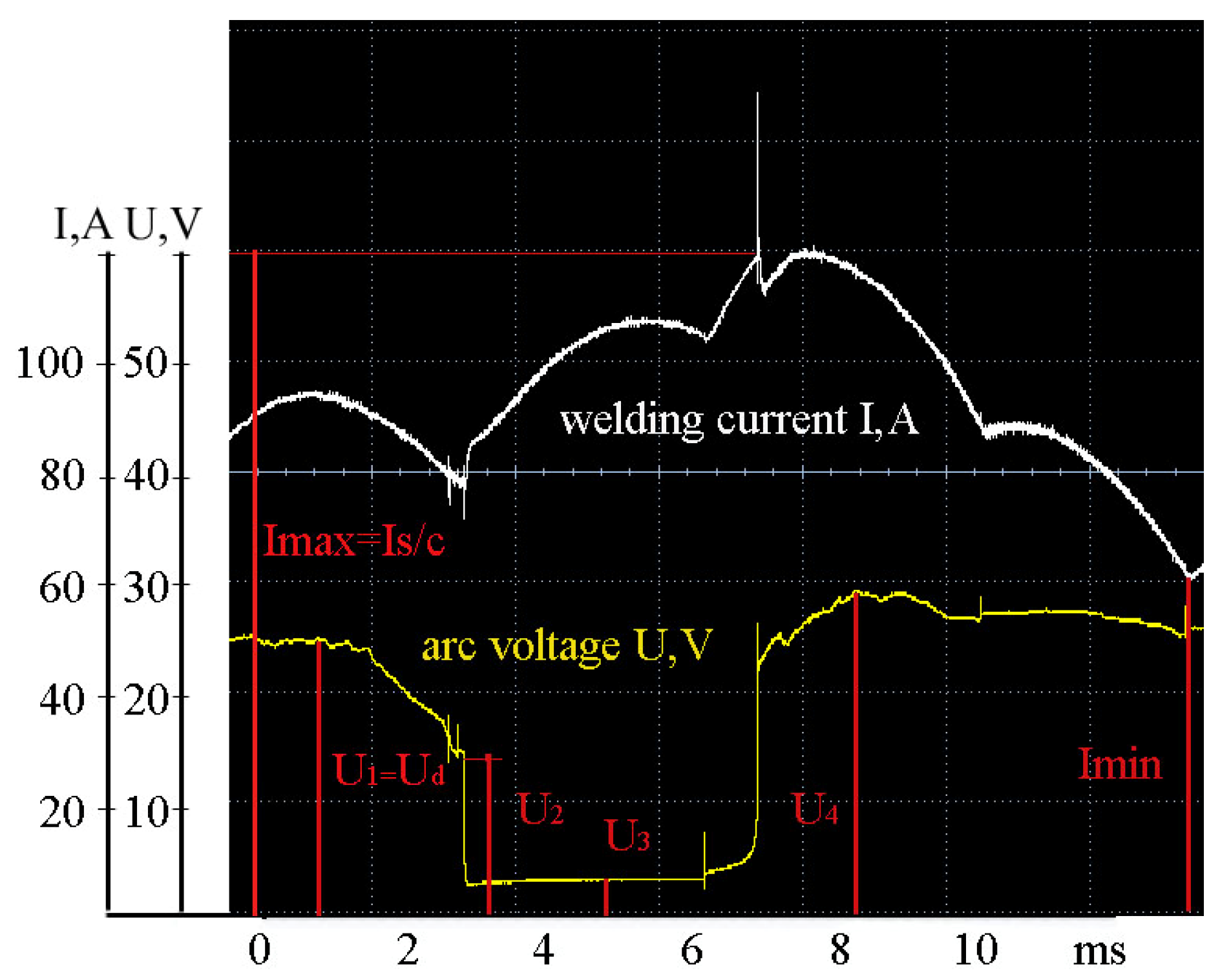
- τs/c is the residence time of the droplet at the end of the electrode, s;
- a is a coefficient of 0.33 × 10⁻⁴ g/s³;
- π is a mathematical constant equal to the ratio of the circumference to the length of the diameter, irrational number ≈ 3.14;
- γ is the density of liquid metal, g/mm³;
- R is the radius of surface curvature of the droplet, mm;
- r0 is the radius of the electrode rod, mm.
- –
- reduction of the volume of transferred droplets of molten electrode metal to the weld pool by 24% on average, which increases the transfer of chemical elements from the electrode to the weld metal;
- –
- reduction of the average duration of arc burning in the intervals of electrode melting and formation of electrode metal droplets by 36% on average, which contributes to the reduction of overheating of the welded product.

| Brand of Electrode | Elements Content, wt. % | ||||||
|---|---|---|---|---|---|---|---|
| C | Si | Mn | S | P | Сr | Ni | |
| CL11 | 0.05–0.09 | less than 0.70 | 1.50–2.00 | less than 0.018 | less than 0.025 | 18.50–20.50 | 9.00–10.50 |
| LB-52U | 0.11 | 0.2 | 0.41 | 0.010 | 0.021 | 0.04 | 0.02 |
| UONI13/55 | 0.07 | 0.4 | 0.38 | 0.020 | 0.020 | 0.02 | 0.03 |
| Name | Substance | ||||
|---|---|---|---|---|---|
| Mn | Si | Cr | Ni | С Graphite | |
| Melting point, K | 1517 | 1688 | 2130 | 1726 | 3820 |
| Boiling point, K | 2235 | 2623 | 2945 | 3005 | 5100 |
| Heat of vaporization, kJ/mol | 221 | 383 | 342 | 378.6 | - |
| Density, g/cm3 | 7.21 | 2.33 | 7.19 | 8.9 | 2.25 |
| Electrode, Type of Power Supply: Rectifier | Si, % | Mn, % | Cr, % | Ni, % |
|---|---|---|---|---|
| CL11, diode | 0.29 ± 0.02 | 2.44 ± 0.08 | 11.43 ± 0.19 | 8.10 ± 0.16 |
| CL11, inverter | 0.39 ± 0.02 | 2.48 ± 0.08 | 11.85 ± 0.19 | 8.59 ± 0.16 |
| LB 52U, diode | 0.17 ± 0.02 | 0.72 ± 0.03 | 0.05 ± 0.01 | 0.05 ± 0.08 |
| LB 52U, inverter | 0.33 ± 0.02 | 1.00 ± 0.05 | 0.08 ± 0.01 | 0.06 ± 0.08 |
| UONI 13/55, diode | 0.25 ± 0.02 | 0.94 ± 0.05 | 0.05 ± 0.01 | 0.06 ± 0.08 |
| UONI 13/55, inverter | 0.33 ± 0.02 | 1.10 ± 0.05 | 0.10 ± 0.01 | 0.06 ± 0.08 |
| Electrodes | Type of Power Supply: Rectifier | СаО, % | SiO2, % | TiO2, % | NbO, % | MnO, % | Fe2O3, % | Cr2O3, % | Al203, % |
|---|---|---|---|---|---|---|---|---|---|
| CL11 | diode | 62.33 | 12.48 | 7.27 | 6.31 | 3.53 | 3.52 | 3.29 | 1.27 |
| inverter | 60.64 | 12.14 | 6.31 | 5.67 | 3.48 | 8.26 | 2.74 | 0.76 | |
| LB-52U | diode | 38.66 | 25.37 | 9.57 | 0.05 | 7.48 | 15.09 | 0.17 | 3.61 |
| inverter | 36.27 | 24.18 | 8.74 | 0.10 | 7.21 | 19.69 | 0.15 | 3.66 | |
| UONI 13/55 | diode | 50.95 | 24.18 | 3.95 | 0.02 | 5.80 | 7.53 | - | 7.57 |
| inverter | 47.44 | 23.65 | 3.84 | 0.02 | 4.93 | 12.96 | - | 7.16 |
- Increase in the mass percentage of alloying elements in the weld metal:
- Si from 0.29% to 0.39% using CL11, from 0.17% to 0.33% using LB-52U, and from 0.25% to 0.33% using UONI13/55;
- Mn from 2.44% to 2.48% using CL11, from 0.72% to 1.00% using LB-52U, and from 0.94% to 1.1% using UONI13/55;
- Cr from 11.43% to 11.85% using CL11, from 0.05% to 0.08% using LB-52U, and from 0.05% to 0.1% using UONI13/55.
- Decrease in the percentage of oxides 5% (SiO2, MnO) in the slag phase.
4. Conclusions
- The use of inverter power sources for manual arc welding with coated electrodes provides increased stability of the welding process as well as heat and mass transfer efficiency in comparison with diode rectifiers:
- reduction of the volume of droplets transferred to the weld pool by 24% on average, which increases the efficiency of chemical elements transfer from the electrode to the weld metal;
- reduction of the average duration of arc burning in the intervals of electrode melting and formation of electrode metal droplets by 36% on average, which contributes to the reduction of overheating of the welded product;
- It has been demonstrated that an increase in the rate of change of the main energy parameters of one microcycle of the welding mode (on average doubled) when using an inverter rectifier in comparison with diode rectifiers provides:
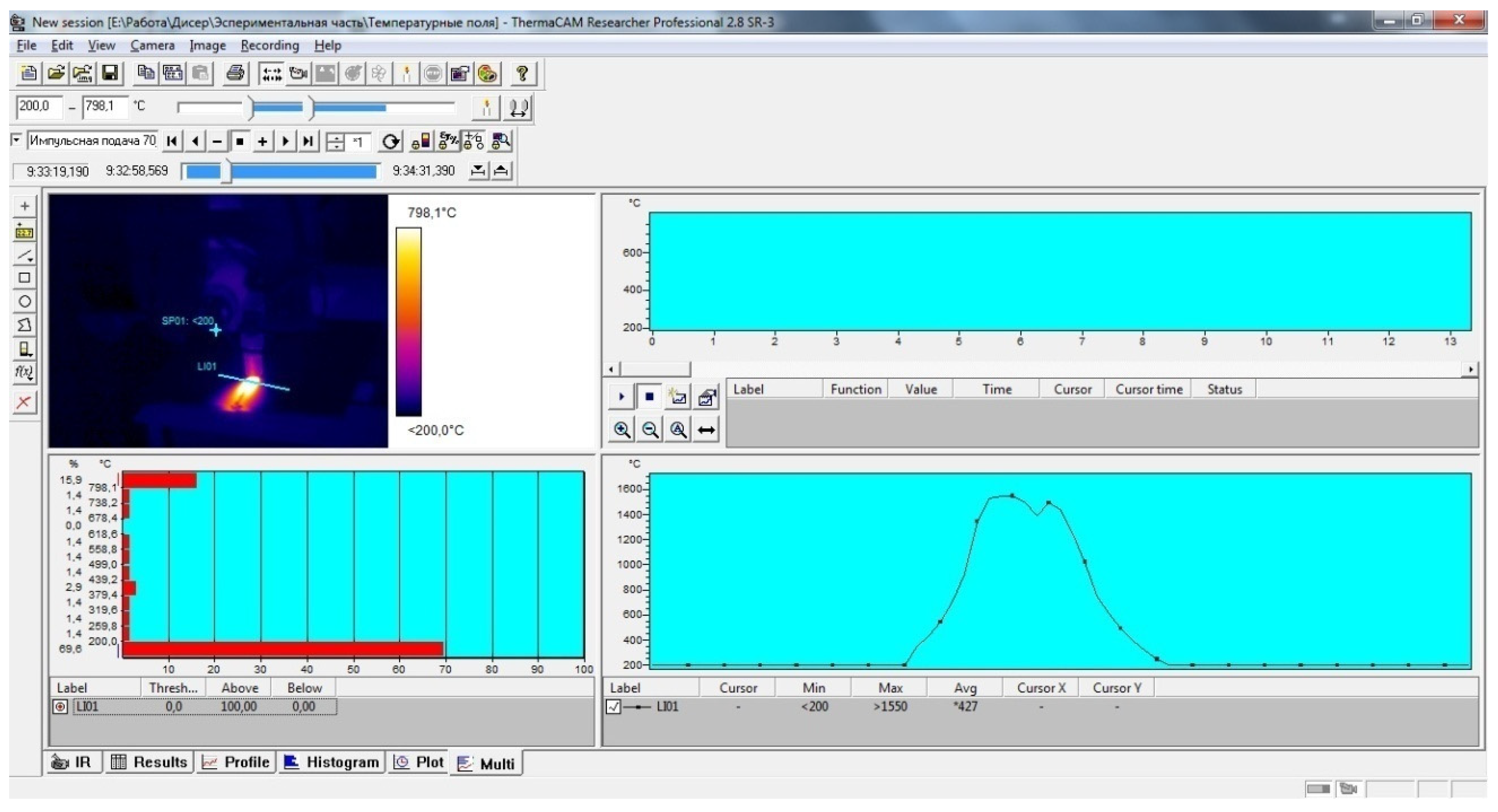
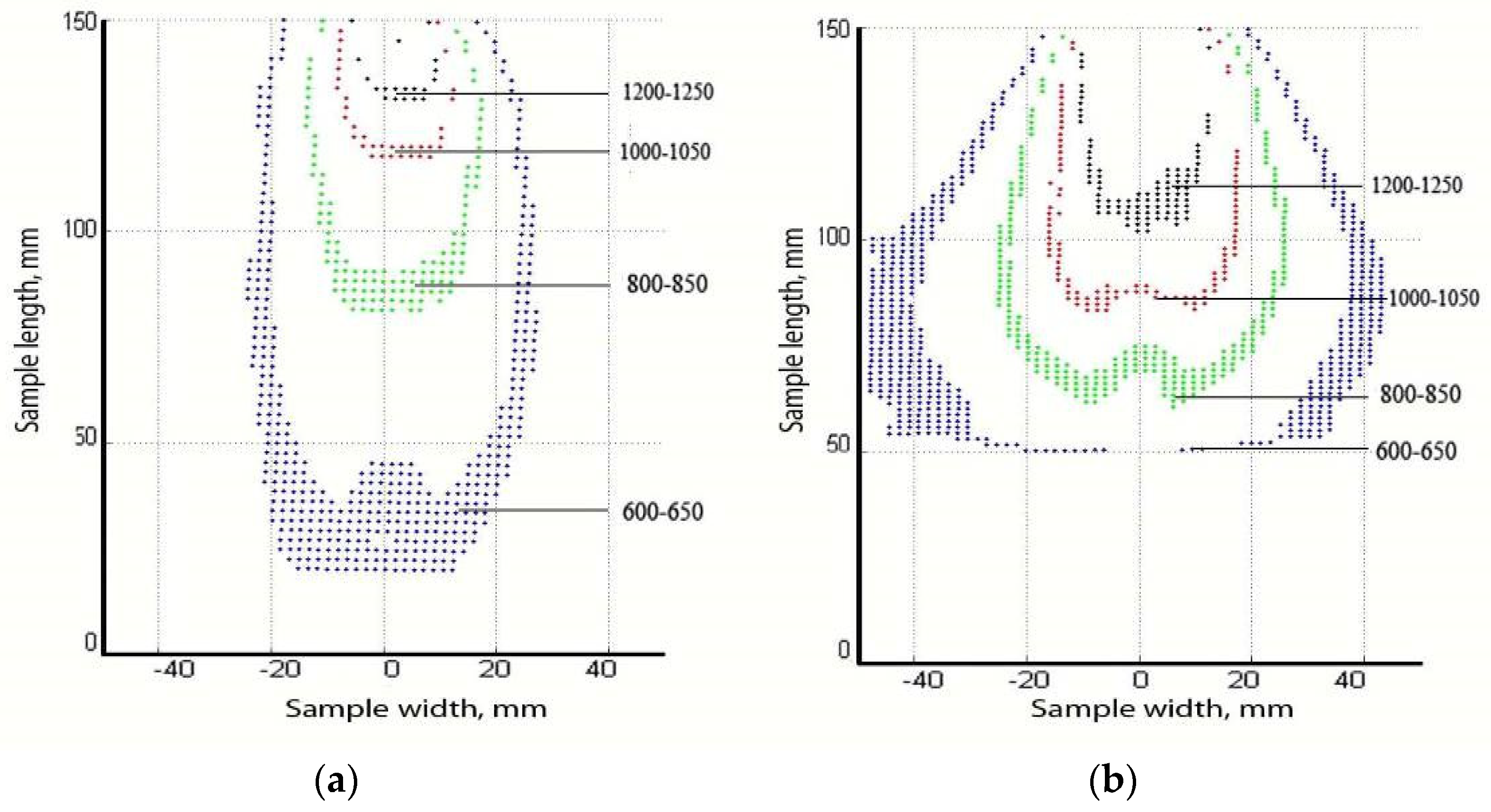
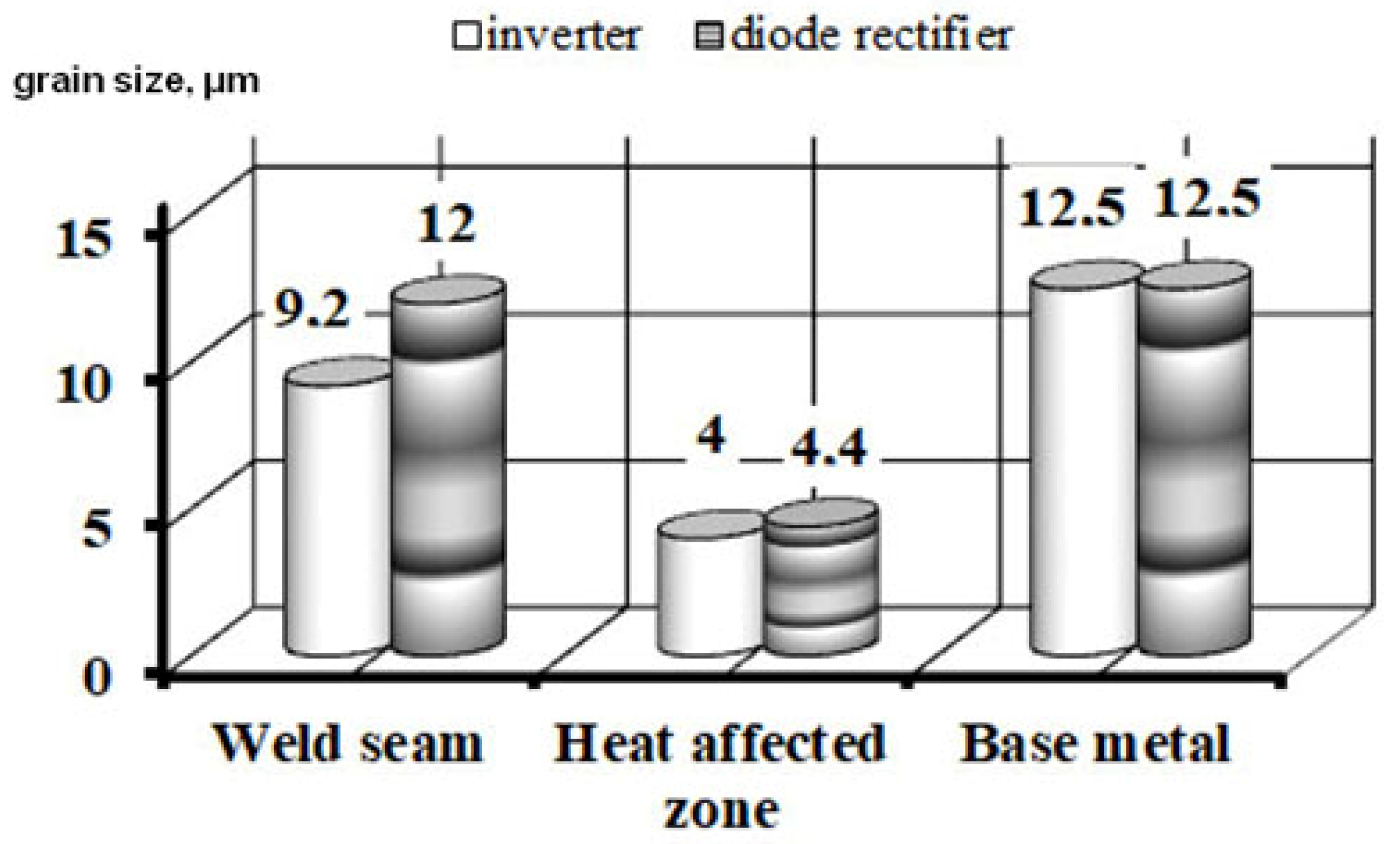
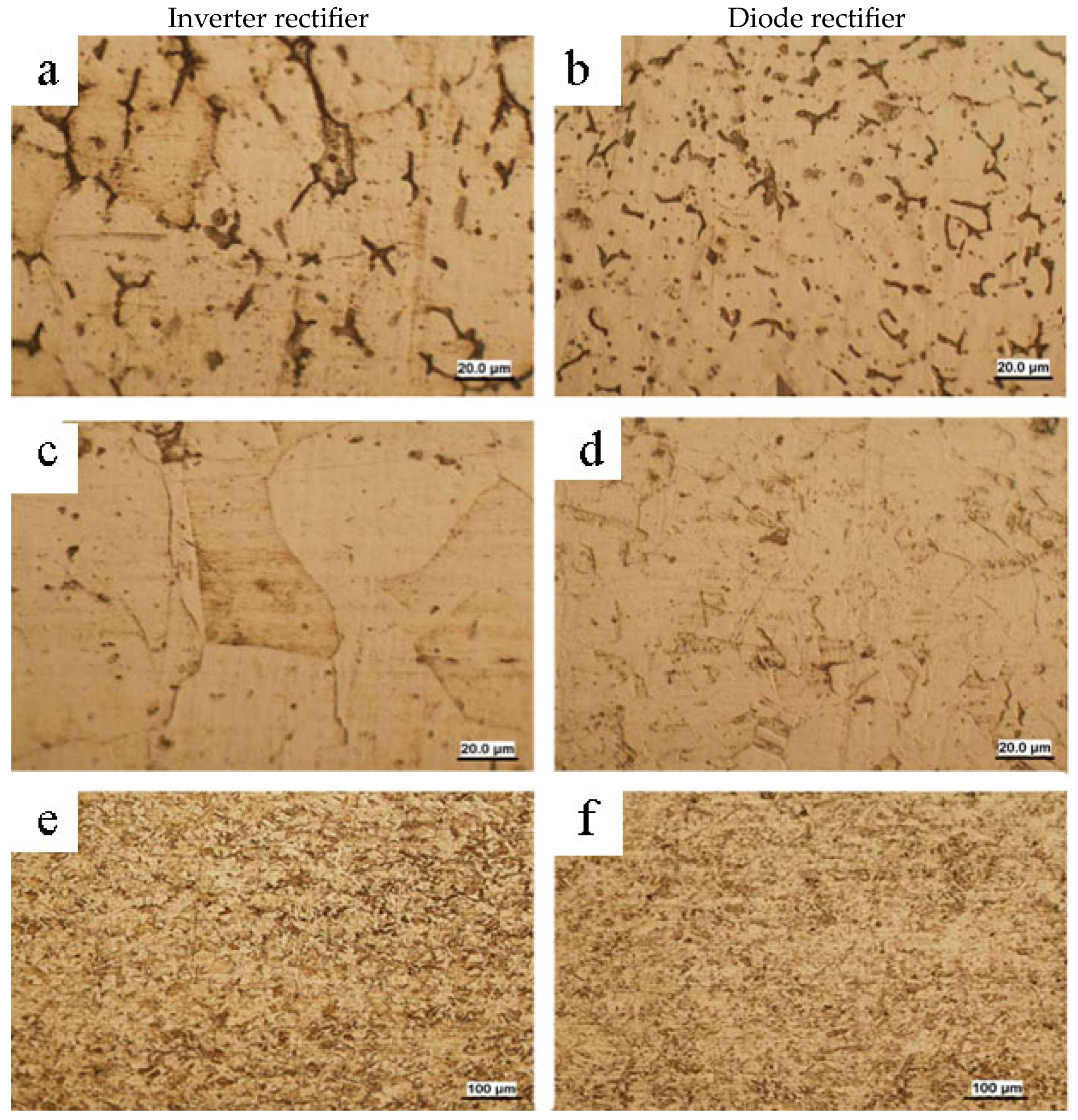
- reduction of the heat content of electrode metal droplets (on average by 15%) contributes to a reduction of the width of temperature fields on the surface of the welded product by 25%, the area of HAZ by 15%, and the width of HAZ by 36%.
- improved structure of the welded joint by reducing the grain size of the clad metal by 30% on average and the HAZ by 35% on average, as well as the welded joint due to the increased impact toughness by 15%.
Author Contributions
Funding
Data Availability Statement
Conflicts of Interest
References
- Vlasov, A.; Makarenko, N.; Holub, D.; Kushchii, H.; Titarenko, V. Increasing of efficiency of manual arc welding and surfacing of engineering products. Sci. J. Ternopil Natl. Tech. Univ. 2018, 91, 46–55. [Google Scholar] [CrossRef]
- Milyutin, V.S. Testing the Welding Properties of Arc Welding Equipment; ESAB: Yekaterinburg, Russia, 2019; 466p. [Google Scholar]
- Il’yaschenko, D.P.; Chinakhov, D.А.; Gotovshchik, Y.M. MAW Productivity Development and Reduction of its Harmful Effect on Human Organisms. Appl. Mech. Mater. Sci. J. 2014, 682, 122–126. [Google Scholar] [CrossRef]
- Lebedev, V.A.; Sorokin, M.S.; Belov, A.A. Algorithms for controlling inverter sources of welding current to optimize the electrode metal transfer parameters. Weld. Int. 2014, 28, 957–961. [Google Scholar] [CrossRef]
- Słania, J.; Slazak, B. Analysis of the Covered Electrode Welding Process Stability on the Basis of Linear Regression Equation. Arch. Metall. Mater. 2014, 59, 905–909. [Google Scholar] [CrossRef]
- Lebedev, V.A.; Krot, A.F.; Yurashevich, V.G. A method for controlling molten droplet transfer in mechanized welding. Weld. Int. 2013, 27, 702–704. [Google Scholar] [CrossRef]
- Dyurgerov, N.G.; Morozkin, I.S.; Lenivkin, V.A. Integral self-regulation in arc welding processes. Weld. Int. 2017, 31, 713–716. [Google Scholar] [CrossRef]
- Ohara, M.; Mizuguchi, T.; Miyata, K.; Tsuyama, T.; Fujiwara, K. A new approach to controlling metal transfer by dynamic modification in gas composition of arc atmosphere: Studies on pulsed gas MAG welding. Weld. Int. 2020, 34, 430–454. [Google Scholar] [CrossRef]
- Ślązak, B. Analysis of instantaneous values of current and voltage parameters in the evaluation of process stability of shielded electrode welding. Weld. Int. 2016, 30, 33–37. [Google Scholar] [CrossRef]
- Lankin, Y.N. Stability parameters of manual metal arc welding. Autom. Weld. 2011, 1, 7–15. [Google Scholar]
- Skrzyniecki, K.; Kolasa, A.; Cegielski, P. Study of static and dynamic characteristics of welding power source-arc systems. Weld. Int. 2015, 29, 865–867. [Google Scholar] [CrossRef]
- Rykała, J.; Pfeifer, T. Influence of the technological conditions of welding using the MIG/MAG method on metal transfer in the welding arc. Weld. Int. 2014, 28, 931–940. [Google Scholar] [CrossRef]
- Sas, A.V.; Sorokin, V.N.; Chernov, A.V. Ensuring the Stability of Arc Welding Process when Using Inverter Power Sources. Glob. Nucl. Saf. 2017, 22, 46–53. Available online: https://cyberleninka.ru/article/n/obespechenie-stabilnosti-protsessa-dugovoy-svarki-pri-ispolzovanii-invertornyh-istochnikov-pitaniya (accessed on 21 March 2024). [CrossRef]
- Yun, D.H.; Lee, W.S.; Lee, J.Y.; Lee, I.O. A 3-leg inverter-based high-frequency welding power supply capable of AC 220 and 440-V operation. IEEE Trans. Power Electron. 2021, 36, 12877–12888. [Google Scholar] [CrossRef]
- Kar, A.; Sengupta, M. Design, analysis and experimental validation of a variable frequency silicon carbide-based resonant-converter for welding applications. Sādhanā 2021, 46, 75. [Google Scholar] [CrossRef]
- Jamrozik, W.; Górka, J. Assessing MMA Welding Process Stability Using Machine Vision-Based Arc Features Tracking System. Sensors 2021, 21, 84. [Google Scholar] [CrossRef] [PubMed]
- Jabavathi, J.D.; Sait, H. Design of a single chip PWM driver circuit for inverter welding power source. IEEE Trans. Circuits Syst. II Express Briefs 2019, 67, 720–724. [Google Scholar] [CrossRef]
- Marneni, A.; Sivani, A.S.; Kumar, S.S.; Babu, N.; Padmanaban, N. Analysis and Control of Energy Efficient Welding Machine Test Bed Employing SiC based Power Electronic Converter. In Proceedings of the 2023 11th National Power Electronics Conference (NPEC), Guwahati, India, 14–16 December 2023; pp. 1–6. [Google Scholar]
- Shatilo, S.P. Model of electrode metal transfer at manual arc welding. Weld. Prod. 1995, 9, 3–5. [Google Scholar]
- Qin, R. Critical Assessment of the Electric Effect in Electric Arc Welding. Metals 2021, 11, 1917. [Google Scholar] [CrossRef]
- Novozhilov, N.M. Fundamentals of Metallurgy of Arc Welding in Gases; Mashinostroenie: Moscow, Russia, 1979; 231p. [Google Scholar]
- Erokhin, A.A. Fundamentals of Fusion Welding. Physico-Chemical Regularities; Mashinostroenie: Moscow, Russia, 1973; 448p. [Google Scholar]
- Pokhodnya, I.K. (Ed.) Metallurgy of Arc Welding: Processes in the Arc and Electrode Fusion; Naukova Dumka: Kiev, Ukraine, 1990; 222p. [Google Scholar]
- Sindo, K. Welding Metallurgy; Wiley-Interscience; University of Wisconsin: Madison, WI, USA, 1987. [Google Scholar]
- Mills, K.C.; Seethharaman, S. Fundamentals of Metallurgy; Woodhead Publishing: Abington, UK, 2005. [Google Scholar]
- Leskov, G.I. Electric Welding Arc; Mashinostroenie: Moscow, Russia, 1970; 335p. [Google Scholar]
- Bagryanskiy, K.V. Theory of Welding Processes; Vishcha Shkola Publishing House: Kiev, Ukraine, 1976; 424p. [Google Scholar]
- Fedko, V.T. Melting and transfer of the electrode metal at arc welding with coated electrodes. Weld. Int. 2003, 2, 3–10. [Google Scholar] [CrossRef]
- Neves, A.C.; Sartori Moreno, J.R.; Corrêa, C.A.; Trevisani Olívio, E.F. Study of arc welding stability in flux cored arc welding process and pulsed continuous current. Weld. Int. 2021, 35, 158–169. [Google Scholar] [CrossRef]
- Bulychev, V.V.; Golubina, S.A.; Latypova, G.R. Prediction of manufacturing process stability in electric arc welding of metals. Electrometallurgy 2019, 8, 24–29. [Google Scholar]
- Lukić, U.; Prokić-Cvetković, R.; Popović, O.; Rajičić, B.; Serbia, B.; Jovičić, R.; Burzić, M. Impact Of Welding Parameters On The Stability Of Gas Metal Arc Welding Process. In Proceedings of the 18th International Research/Expert Conference “Trends in the Development of Machinery and Associated Technology” TMT 2014, Budapest, Hungary, 10–12 September 2014. [Google Scholar]
- Guilherme, L.H.; Benedetti, A.V.; Fugivara, C.S.; Magnabosco, R.; Oliveira, M.F. Effect of MAG welding transfer mode on sigma phase precipitation and corrosion performance of 316L stainless steel multi-pass welds. Integr. Med. Res. 2020, 9, 10537–10549. [Google Scholar] [CrossRef]
- Vaz, C.T.; Bracarense, A.Q. The Effect of the Use of PTFE as a Covered-Electrode Binder on Metal Transfer. Soldag. Insp. 2013, 20, 160–170. [Google Scholar] [CrossRef]
- Vaz, C.T. Influência do Polímero Utilizado como Aglomerante em Eletrodos Revestidos Básicos Sobre a Formação de Ferrita Acicular no Metal de Solda. Ph.D. Thesis, Universidade Federal de Minas Gerais, Belo Horizonte, Brazil, 2014. [Google Scholar]
- García Rodríguez, A.; Miguel Oria, J.V.; Gómez, A.D. Theoretical and empirical assessment of evaluation methods of the electric charge transference in welding with covered electrodes. Weld. Int. 2016, 30, 527–534. [Google Scholar] [CrossRef]
- Chen, J.H.; Fan, D.; He, Z.Q.; Ye, J.; Luo, Y.C. A study of the mechanism for globular metal transfer from covered. Weld. J. 1989, 68, 145s–150s. [Google Scholar]
- Brandi, S.D.; Taniguchi, C.; Liu, S. Analysis of metal transfer in shielded metal arc welding. Weld. J. 1991, 70, 261s–270s. [Google Scholar]
- Lancaster, J.F. Metallurgy of Welding, 5th ed.; Chapman & Hall: London, UK, 1993. [Google Scholar]
- Lancaster, J.F. The Physics of Welding, 2nd ed.; Pergamon: Oxford, UK, 1986. [Google Scholar]
- Ivanov, V.P.; Leshchinskiy, L.K.; Stepnov, K.K. Control of the alloying process of weld metal of variable chemical composition. Weld. Int. 2021, 35, 441–446. [Google Scholar] [CrossRef]
- Letyagin, I.Y. Using Mathematical Modeling To Develop Electrode Coating Composition For Stable Arcing And Arc Restarting. Solid State Phenom. 2017, 265, 445–449. [Google Scholar] [CrossRef]
- Votinova, E.B.; Shalimov, M.P.; Razikov, N.M. Methodology of determination of partial transition coefficients of elements at manual arc welding. Weld. Diagn. 2012, 2, 28–31. [Google Scholar]
- Votinova, E.B.; Shalimov, M.P. Development of the calculation methodology of the weld metal composition at welding with coated electrodes or flux-cored wire. Weld. Diagn. 2011, 5, 31–36. [Google Scholar]
- Il’yaschenko, D.P.; Chinakhov, D.A.; Chinakhova, E.D.; Kirichenko, K.Y.; Verkhoturova, E.V. Assessment Of Negative Influence Of Manganese In Welding Fumes On Welder’s Health And Ways To Reduce It. FME Trans. 2020, 48, 75–81. [Google Scholar] [CrossRef]
- Kirichenko, K.Y.; Vakhniuk, I.A.; Rogulin, R.S.; Kirichenko, A.V.; Gridasov, A.V.; Kosyanov, D.Y.; Drozd, V.A.; Piekoszewski, W.; Golokhvast, K.S.; Kholodov, A.S. Characteristics Of Fume Sedimentation In The Working Zone During Arc Welding With Covered Electrodes. Toxicol. Environ. Chem. 2019, 101, 463–474. [Google Scholar] [CrossRef]
- Golovatyuk, A.P.; Sidoruk, V.S.; Levchenko, O.G.; Zatserkovny, S.A.; Taraborkin, L.A. Intensity of aerosols formation at manual welding with modulated current. Autom. Weld. 1985, 2, 39–40. [Google Scholar]
- Il’yashchenko, D.P.; Zernin, E.A.; Shadskii, S.V. Chemical composition of welding aerosol in manual coated electrode arc welding. Weld. Int. 2011, 25, 719–721. [Google Scholar] [CrossRef]
- Gomes, J.F.P.; Albuquerque, P.C.S.; Miranda, R.M.M.; Vieira, M.T.F. Determination of airborne nanoparticles from welding operations. J. Toxicol. Environ. Health Part A 2012, 75, 747–755. [Google Scholar] [CrossRef]
- Belokon, V.M.; Lukyanchikov, I.A.; Dondo, D.A. Movement of Molten Electrode Metal Droplets during Welding in CO2. Bull. Belarusian-Russ. Univ. 2011, 2, 6–12. Available online: https://cyberleninka.ru/article/n/dvizhenie-kapel-rasplavlennogo-elektrodnogo-metalla-pri-svarke-v-so2 (accessed on 11 April 2024).
- Makarenko, V.D.; Shatilo, S.P. Calculation of kinetic characteristics of electrode droplets at their transition through the arc gap in the process of welding with coated electrodes. Weld. Prod. 1999, 14, 6–10. [Google Scholar]
- Kosheleva Natalya, N.; Zakharova Dinara, Z. Application of the Concept “Root of the N-th Degree” in Solving Cubic Equations. Cardano formula. ANI Pedagog. Psychol. 2021, 1, 162–164. Available online: https://cyberleninka.ru/article/n/primenenie-ponyatiya-koren-n-oy-stepeni-pri-reshenii-kubicheskih-uravneniy-formula-kardano (accessed on 11 April 2024).
- Ilyashchenko, D.P.; Chinakhov, D.A.; Kirichenko, K.Y.; Sydorets, V.N. Mathematical formula to determine geometrical dimensions of electrode metal droplets transferred with short circuits. Mater. Sci. Forum 2018, 938, 1–6. [Google Scholar] [CrossRef]
- Makarenko, V.D.; Paliy, R.V.; Mukhin, M.Y. Technological Properties of Assembly Welding of Pipelines; Makarenko, V.D., Ed.; Nedra-Business Center: Moscow, Russia, 2001; 118p. [Google Scholar]
- Belousov Yuriy, V. Calculations of Thermal Processes of the High-Temperature Area of the Surface Heat Sources at Welding. GVUZ “Priazovsky State Technical University”. 2000. Available online: https://cyberleninka.ru/article/n/raschety-teplovyh-protsessov-vysokotemperaturnoy-oblasti-poverhnostnyh-istochnikov-teploty-pri-svarke (accessed on 13 April 2024).
- Ilyashchenko, D.P.; Chinakhov, D.A. Influence of the power source type on heat and mass transfer at manual arc welding. Weld. Diagn. 2010, 6, 26–29. [Google Scholar]
- Gorpenyuk, V.N.; Makarenko, V.D.; Ponomarev, V.E. On the possibility of predicting the porosity in the weld seam with the help of electronic devices when welding with coated electrodes. In Saving of Material, Energy and Labor Resources in Welding Production; Publishing House of Chelyabinsk State University: Chelyabinsk, Russia, 1986; pp. 341–342. [Google Scholar]
- Górka, J.; Janicki, D.; Fidali, M. Thermographic Assessment of the HAZ Properties and Structure of Thermomechanically Treated Steel. Int. J. Thermophys. 2017, 38, 183. [Google Scholar] [CrossRef]
- Erofeev, V.A.; Strakhova, E.A. Estimation of probability of conformity of weld quality indicators to the specified tolerances in the development of welding technology. Prep. Ind. Mech. Eng. 2019, 17, 345–349. [Google Scholar]
- Sholokhov, M.A.; Melnikov, A.Y.; Buzorina, D.S.; Smorodinsky, Y.G. Development of an approach to forcast the defect formation in the end of a weld joint based on the modeling of heat processes. Russ. J. Nondestruct. Test. 2020, 56, 460–467. [Google Scholar] [CrossRef]
- Filiakov, A.E.; Poloskov, S.I.; Erofeev, V.A.; Sholokhov, M.A. Physical and Mathematical Model of Influence of Deviations of Arc Energy Parameters on Defects Formation at Welding of Pipelines. Weld. Diagn. 2020, 2, 16–22. [Google Scholar]
- Yapp, D.; Blackman, S.A. Recent Developments in High Productivity Pipeline Welding. J. Braz. Soc. Mech. Sci. Eng. 2004, 26, 89–97. [Google Scholar] [CrossRef]
- Makarenko, V.D.; Muravyev, K.A.; Kalyanov, A.I. Features of manual arc welding of root seams of non-rotating joints of oil pipelines operated in Western Siberia. Weld. Prod. 2005, 12, 38–41. [Google Scholar]
- Ilyaschenko, D.P.; Kryukov, A.V.; Lavrova, E.V.; Kuznetsov, M.A.; Verkhoturova, E.V. Determination of Parameters of Electrode Metal Transported Drops by Simulation and Visualization. Devices Methods Meas. 2020, 11, 222–227. [Google Scholar] [CrossRef]
- Ilyashchenko, N.V.P. Certificate of Registration of Computer Programs No. 2015615010. Calculation of Heat Deposition in a Drop of Electrode Metal at RDS/D.P. 6 May 2015. Available online: https://portal.tpu.ru/portal/pls/portal/docs/1/16047790.JPEG (accessed on 14 June 2024).
- Ilyashchenko, D.P.; Pavlov, N.V.; Chinakhov, D.A. Comparative analysis of heat distribution in the product at fusion arc welding. Repair Restor. Mod. 2011, 3, 35–37. [Google Scholar]
- Chinakhov, D.A.; Il’yashchenko, D.P. The Influence of Two-Jet Gas Shielding Parameters on the Structure and Microhardness of Steel 45 Joints during Consumable Electrode Welding. Metals 2023, 13, 1136. [Google Scholar] [CrossRef]
- Marques, E.S.V.; Silva, F.U.G.; Pereira, A.B. Comparison of finite element methods in fusion welding processes-a review. Metals 2020, 10, 75. [Google Scholar] [CrossRef]
- Sapozhkov, S.B.; Zernin, E.A.; Petrova, E.D.; Petrov, R.V.; Zakharov, M.A. Application of Nano- and Ultradisperse Materials for Control of Structure and Properties of Metals in Joining Technologies: World Practice (Review). Vestnik NovSU. 2023. Available online: https://cyberleninka.ru/article/n/primenenie-nanoi-ultradispersnyh-materialov-dlya-upravleniya-strukturoy-i-svoystvami-metallov-v-soedinitelnyh-tehnologiyah-mirovaya (accessed on 13 April 2024).
- Ilyashchenko, D.P.; Chinakhov, D.A.; Verkhoturova, E.V.; Lavrova, E.V. Stability Of MMA Welding With Protective Coatings. Struct. Integr. Life 2020, 20, 33–36. [Google Scholar]
- Rybin, V.S.; Scherbakov, I.A. Model of welding thermal processes with a limited number of fictitious point sources. Ferrous metallurgy. Bull. Sci.-Tech. Econ. Inf. 2022, 78, 435–444. [Google Scholar]
- Sheshukov, O.Y.; Nekrasov, I.V.; Metelkin, A.A.; Lozovaya, E.Y.; Shevchenko, O.I.; Savelyev, M.V. Modern Steel: Theory and Technology; Textbook: Recommended by the Methodical Council of the Ural Federal University for Students of the University, Studying in the Fields of Training 22.03.02, 22.04.02—Metallurgy; Mironova, M.V., Ed.; Nizhny Tagil Technological Institute (branch) of UrFU: Nizhny Tagil, Russia, 2020; 400p, Available online: https://elar.urfu.ru/handle/10995/94364 (accessed on 14 June 2024).
- Panteleenko, F.I.; Mamonov, A.M. Installation for low-deformation welding of stainless steels with dry ice. Foundry Prod. Metall. 2022, 2, 54–58. [Google Scholar] [CrossRef]
- Mamadaliev, R.A.; Bakhmatov, P.V.; Martyushev, N.V.; Skeeba, V.Y.; Karlina, A.I. Influence Of Welding Regimes On Structure And Properties Of Steel 12kh18n10t Weld Metal In Different Spatial Positions. Metallurgist 2022, 65, 1255–1264. [Google Scholar]
- Vicente, A.A.; Silva AC, S.; Torres Lopez, E.A.; Pereira, M.; Santos, T.F.; Tenório, J.A. The possible solidification modes of austenitic stainless steels joints according to different chemical compositions and cooling rates. Weld. Int. 2024, 38, 187–197. [Google Scholar] [CrossRef]
- Mamadaliev, R.A.; Bakhmatov, P.V. Distribution of alloying elements in multi-pass welds of chromium-nickel steel. Met. Heat Treat. Met. 2023, 5, 55–60. [Google Scholar]
- Bakhmatov, P.V.; Mamadaliev, R.A.; Kravchenko, A.S. Change in weld metal structure and properties for multi-pass butt welding of stainless steel process piping. In Current Problems and Ways of Industry Development: Equipment and Technologies; Springer: Cham, Switzerland, 2021; pp. 497–506. [Google Scholar]
- Malhotra, D.; Shahi, A.S. Weld metal composition and aging influence on metallurgical, corrosion and fatigue crack growth behavior of austenitic stainless steel welds. Mater. Res. Express 2019, 6, 106555. [Google Scholar] [CrossRef]
- Zhang, T.; Yu, H.; Li, Z.; Kou, S.; Kim, H.J.; Tillmann, W. Progress on effects of alloying elements on bainite formation and strength and toughness of high strength steel weld metal. Mater. Res. Express 2021, 8, 032002. [Google Scholar] [CrossRef]
- Krivonosova, E.A.; Akulova, S.N.; Myshkina, A.V. To the problem of corrosion damage of welded seams. Bulletin of Perm National Research Polytechnic University. Mechanical Engineering. Mater. Sci. 2017, 19, 118–119. [Google Scholar]
- Krivonosova, E.A. Predicting the properties of the metal of welded joints on the basis of the results of quantitative parametrisation of the structure. Weld. Int. 2016, 30, 459–462. [Google Scholar] [CrossRef]
- Krivonosova, E.A. Prediction of weld metal properties based on the results of quantitative structure parameterization. Weld. Prod. 2015, 6, 3–6. [Google Scholar]
- Matvienko, Y.G.; Vasiliev, I.E.; Chernov, D.V.; Marchenkov, A.Y. Diagnostics of welded joints in main pipelines equipment. Sci. Technol. Oil Prod. Pipeline Transp. 2018, 8, 618–630. [Google Scholar]
- AMelakhsou, A.; Batton-Hubert, M. On welding defect detection and causalities between welding signals. In Proceedings of the 2021 IEEE 17th International Conference on Automation Science and Engineering (CASE), Lyon, France, 23–27 August 2021; pp. 401–408. [Google Scholar] [CrossRef]
- Sholokhov, M.A.; Buzorina, D.S.; Lunina, E.V. Efficiency of operation of inverter rectifier power supplies. Weld. Diagn. 2012, 3, 26–29. [Google Scholar]


| Type of Power Supply: Rectifier | Brand of Electrodes | Average Values of Mode Parameters (Oscilloscope AKIP-4122/1 V (AKIP, China)) | Number of Short Circuits during Cladding Time |
|---|---|---|---|
| diode | LB-52U | Current: 83 + 2.7 A Voltage: 20.8 + 0.6 V Projected welding speed: 0.25 m/min | 17 |
| inverter | 22 | ||
| diode | UONI13/55 | Current: 83 + 2.7 A Voltage: 21.5 + 0.6 V Projected welding speed: 0.29 m/min | 17 |
| inverter | 22 | ||
| diode | CL11 | Current: 84 + 2.7 A Voltage: 24.5 + 0.6 V Projected welding speed: 0.27 m/min | 12 |
| inverter | 24 |
| Parameters | Type of Power Supply: Rectifier | Brand of Electrode | ||
|---|---|---|---|---|
| LB-52U | UONI13/55 | CL11 | ||
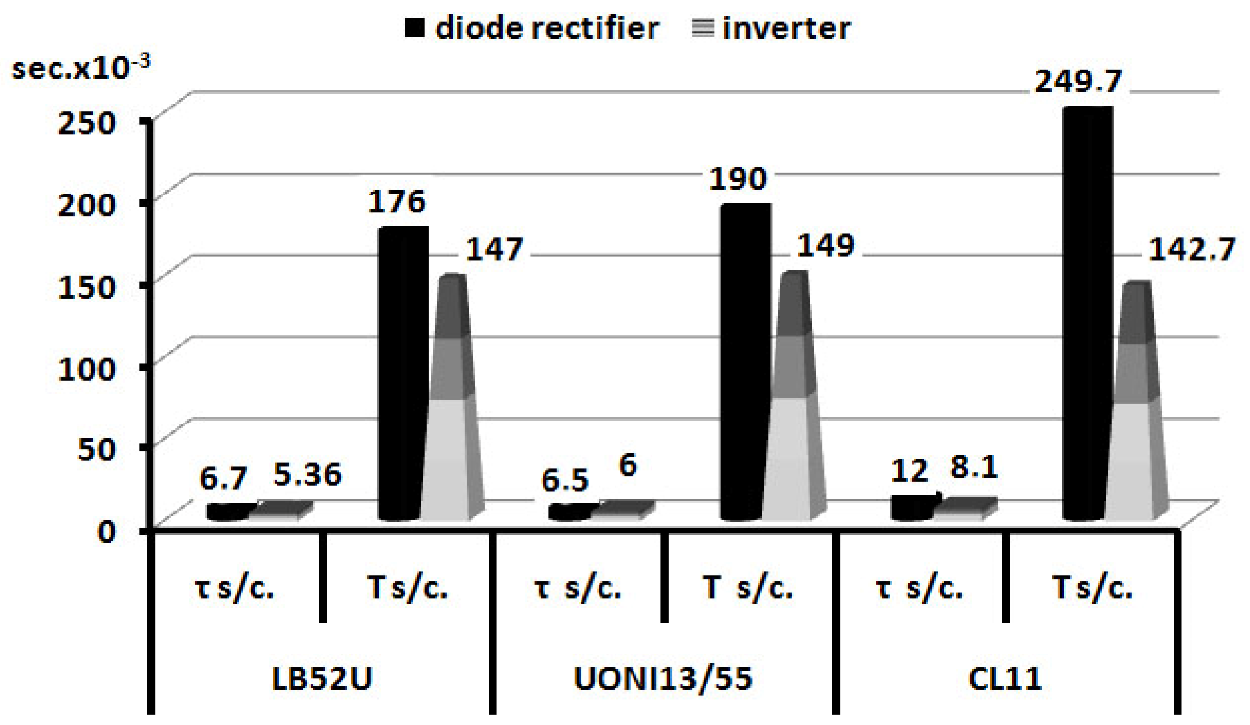
| Short-circuit duration of the arc interval τs/c, µs | Diode | 6.7 | 6.5 | 12 |
| Inverter | 5.36 | 6 | 8.1 | |
| RMS deviation of short-circuit duration, στs/c, ms | Diode | 1.85 | 2.1 | 3.8 |
| Inverter | 1.34 | 1.9 | 2.3 | |
| Coefficient of short-circuit duration variation, КVτs/c, % | Diode | 27.6 | 32.3 | 28 |
| Inverter | 25 | 31.9 | 28.7 | |
| Cycle duration, Ts/c, ms | Diode | 179 | 190 | 249.7 |
| Inverter | 147 | 149 | 142.7 | |
| RMS deviation of cycle duration σ Ts/c., ms | Diode | 52 | 52 | 58.7 |
| Inverter | 15 | 27 | 29.3 | |
| Coefficient of cycle duration variation KVTs/c., % | Diode | 29 | 27.2 | 23 |
| Inverter | 10 | 27.48 | 20 | |
| Parameters | Type of Source: Rectifier | Brand of Electrode | ||
|---|---|---|---|---|
| LB-52U | UONI13/55 | CL11 | ||
| Imax, А | Diode | 109.9 + 3.3 | 115.5 + 2.7 | 118.1 + 3.7 |
| Inverter | 100.2 + 0.8 | 104.2 + 0.6 | 102 + 1.6 | |
| Imin, А | Diode | 61.3 + 3.4 | 63.1 + 2.1 | 65.9 + 4.8 |
| Inverter | 73.1 + 0.8 | 79.3 + 0.8 | 78 + 1.1 | |
| , | Diode | 0.75 | 0.73 | 0.71 |
| Inverter | 0.83 | 0.8 | 0.82 | |
| V of Imax rise, kA/s | Diode | 7.3 + 2.6 | 8.1 + 0.8 | 8.3 + 0.3 |
| Inverter | 15.5 + 1.6 | 15.5 + 1.5 | 11.2 + 0.3 | |
| V of Imin fall, kA/s | Diode | 10.3 + 2.2 | 12.3 + 2.2 | 11.2 + 0.8 |
| Inverter | 18 + 1.1 | 18 + 1.1 | 19 + 1.9 | |
| Brand of Electrode | Power Source | |||||||
|---|---|---|---|---|---|---|---|---|
| Diode Rectifier | Inverter Rectifier | |||||||
| U1, V | U2, V | U3, V | U4, V | U1, V | U2, V | U3, V | U4, V | |
| LB-52U | 16.9 ± 2.5 | 14.1 ± 0.9 | 1.1 ± 0.2 | 40.9 ± 5.8 | 18.4 ± 2.7 | 15.1 ± 1.1 | 0.7 ± 0.2 | 26.5 ± 5.7 |
| UONI 13/55 | 20.4 ± 2 | 15.76 ± 2.4 | 0.7 ± 0.1 | 39.3 ± 5.1 | 19.9 ± 2.8 | 15.4 ± 1.4 | 0.7 ± 0.2 | 24.4 ± 2.3 |
| CL11 | 23.4 ± 4.3 | 21.7 ± 2.4 | 3.5 ± 0.3 | 40.6 ± 4.9 | 23.7 ± 3.5 | 19.7 ± 1.4 | 3 ± 0.2 | 25.2 ± 2.5 |
| Type of Power Supply: Rectifier | Brand of Electrode | τs/c, 10–3 s | Droplet Weight, mg | Droplet Radius, mm | Droplet Volume, mm3 |
|---|---|---|---|---|---|
| Diode | LB-52U | 6.7 ± 1.85 | 0.099 ± 0.002 | 1.39 ± 0.026 | 6.89 ± 1.9 |
| Inverter | 5.36 ± 1.34 | 0.052 ± 0.015 | 1.05 ± 0.01 | 4.36 ± 1.38 | |
| Diode | UONI13/55 | 6.5 ± 2.1 | 0.091 ± 0.004 | 1.3 ± 0.03 | 6.5 ± 1.99 |
| Inverter | 6 ± 1.9 | 0.071 ± 0.002 | 1.23 ± 0.02 | 5.66 ± 1.8 | |
| Diode | CL11 | 12 ± 3.8 | 0.57 ± 0.04 | 2.5 ± 0.05 | 15.48 ± 4.9 |
| Inverter | 8.1 ± 2.3 | 0.175 ± 0.05 | 1.8 ± 0.04 | 10.28 ± 2.9 |
| Type of power Supply: Rectifier | Brand of Electrodes | τs/c., 10–3 s | ΔТs/c Average, °С |
|---|---|---|---|
| Diode | LB-52U | 6.7 ± 1.85 | 694 |
| Inverter | 5.36 ± 1.34 | 1496 | |
| Diode | UONI13/55 | 6.5 ± 2.1 | 888 |
| Inverter | 6 ± 1.9 | 1061 | |
| Diode | CL11 | 12 ± 3.8 | 30 |
| Inverter | 8.1 ± 2.3 | 130 |
| Power Source: Rectifier | Elements Content, wt. % | |||||||
|---|---|---|---|---|---|---|---|---|
| C | Si | Mn | S | P | Сr | Ni | Cu | |
| diode | 0.10 ± 0.012 | 0.52 ± 0.03 | 1.03 ± 0.05 | 0.010 ± 0.002 | 0.014 ± 0.003 | 0.03 ± 0.01 | 0.05 ± 0.01 | 0.03 ± 0.008 |
| inverter | 0.09 ± 0.005 | 0.60 ± 0.03 | 1.23 ± 0.05 | 0.010 ± 0.002 | 0.014 ± 0.003 | 0.03 ± 0.01 | 0.06 ± 0.01 | 0.03 ± 0.008 |
| Type of Power Supply: Rectifier | Elements Content, wt. % | ||||||
|---|---|---|---|---|---|---|---|
| C | Si | Mn | P | Сr | Ni | Cu | |
| diode | 0.11 ± 0.012 | 0.30 ± 0.02 | 0.92 ± 0.05 | 0.019 ± 0.003 | 0.06 ± 0.01 | 0.05 ± 0.01 | 0.09 ± 0.012 |
| inverter | 0.12 ± 0.012 | 0.31 ± 0.02 | 1.00 ± 0.05 | 0.02 ± 0.003 | 0.06 ± 0.01 | 0.06 ± 0.01 | 0.10 ± 0.012 |
| Power Source: Rectifier | Elements Content, wt. % | |||||||
|---|---|---|---|---|---|---|---|---|
| C | Si | Mn | S | P | Сr | Ni | Nb | |
| diode | 0.12 ± 0.012 | 0.80 ± 0.03 | 1.04 ± 0.05 | 0.008 ± 0.002 | 0.018 ± 0.003 | 18.08 ± 0.2 | 9.23 ± 0.16 | 0.70 ± 0.08 |
| inverter | 0.12 ± 0.012 | 0.82 ± 0.03 | 1.23 ± 0.05 | 0.008 ± 0.002 | 0.018 ± 0.003 | 18.45 ± 0.2 | 10.01 ± 0.16 | 0.70 ± 0.08 |
| Steel | Elements Content, wt. % | |||||||
|---|---|---|---|---|---|---|---|---|
| C | Si | Mn | S | P | Сr | Ni | Cu | |
| 45 | 0.42–0.5 | 0.17–0.37 | 0.5–0.8 | <0.035 | <0.03 | <0.25 | <0.30 | <0.30 |
| 09G2S | <0.12 | 0.5–0.8 | 13–1.7 | <0.035 | <0.03 | <0.25 | <0.30 | <0.30 |
| 12H18N10T | <0.12 | <0.8 | <2 | <0.035 | <0.02 | 17–19 | 9–11 | <0.30 |
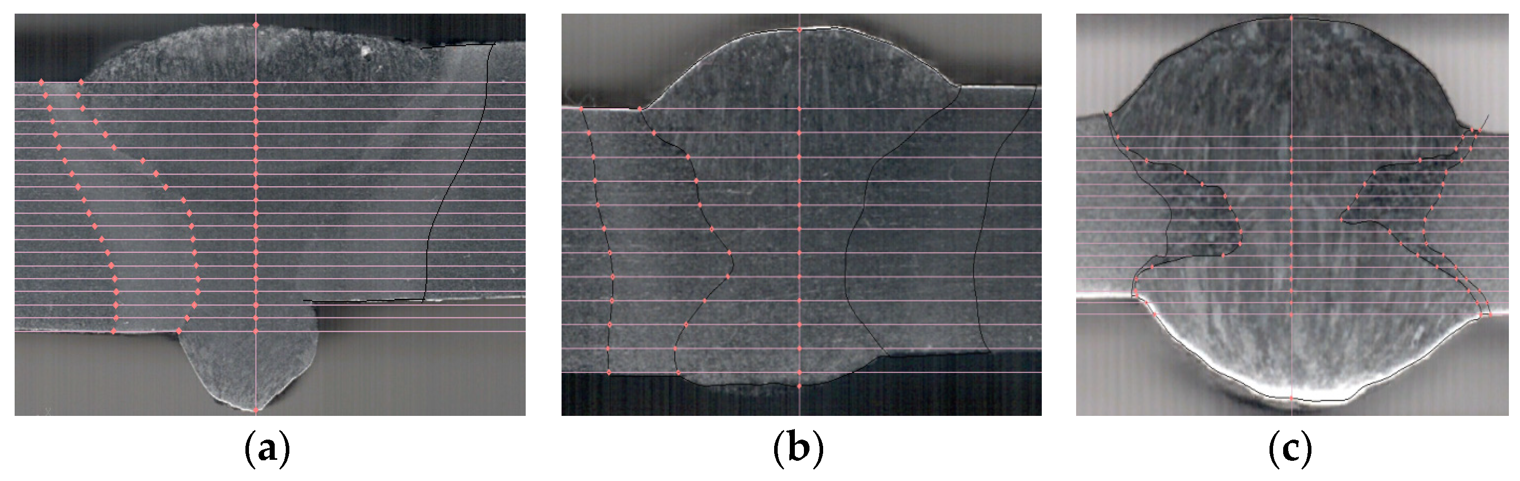
| Steel | Type of Joint According to GOST | Type of Power Supply: Rectifier | Area of Welded Metal, mm2 | Width of Welded Metal, mm | HAZ Area, mm2 | HAZ Width, mm |
|---|---|---|---|---|---|---|
| 45 | С17 thickness 10 mm | Diode | 133 ± 5.1 | 4.06 ± 0.04 | 95.5 ± 2.9 | 5.17 ± 0.04 |
| Inverter | 129 ± 2.6 | 4 ± 0.04 | 80.6 ± 2.8 | 3.34 ± 0.03 | ||
| 09G2S | С17 thickness 6 mm | Diode | 23.6 ± 0.4 | 3.33 ± 2.6 | 51.8 ± 0.53 | 2.08 ± 0.06 |
| Inverter | 21.4 ± 0.3 | 2.89 ± 0.94 | 42.6 ± 0.28 | 1.58 ± 0.04 | ||
| 12H18N10T | С7 thickness 3 mm | Diode | 43.8 ± 0.3 | 3.73 ± 0.07 | 10.3 ± 0.7 | 1.48 ± 0.05 |
| Inverter | 40.1 ± 0.6 | 3.28 ± 0.05 | 6 ± 0.47 | 1.01 ± 0.05 |
| Type of Power Supply: Rectifier | Range of Rupture Strength σB, MPa | Outward, Inward and Rib Bending Angle, deg. | KCU Impact Strength, J/cm2 (Notch in the Center of the Seam) | |||
|---|---|---|---|---|---|---|
| +20 °С | 0 °С | −20 °С | −40 °С | |||
| diode | 542 + 1 | more than 120 | 197 + 12 | 219 + 9 | 226 + 5 | 182 + 21 |
| inverter | 550 + 5 | more than 120 | 219.6 + 3 | 234.6 + 3 | 237 + 3 | 186.8 + 11 |
| Power Source | Range of Rupture Strength σB, MPa | KCU Impact Strength, J/cm2 (Notch in the Center of the Seam) | |||||
|---|---|---|---|---|---|---|---|
| +20 °С | −40 °С | ||||||
| КСU | σKCU | KV.КCU | КСU | σKCU | KV.КCU | ||
| diode rectifier | 648 | 96.5 | 22.15 | 22 | 12.58 | 2.5 | 19 |
| inverter rectifier | 650 | 121 | 13.86 | 11 | 58.3 | 8.35 | 14 |
| Power Source: Rectifier | Range of Rupture Strength σB, MPa | Flow Stress σT, MPa |
|---|---|---|
| diode | 589 ± 1 | 224 ± 26 |
| inverter | 593 ± 1 | 236 ± 36 |
Disclaimer/Publisher’s Note: The statements, opinions and data contained in all publications are solely those of the individual author(s) and contributor(s) and not of MDPI and/or the editor(s). MDPI and/or the editor(s) disclaim responsibility for any injury to people or property resulting from any ideas, methods, instructions or products referred to in the content. |
© 2024 by the authors. Licensee MDPI, Basel, Switzerland. This article is an open access article distributed under the terms and conditions of the Creative Commons Attribution (CC BY) license (https://creativecommons.org/licenses/by/4.0/).
Share and Cite
Il’yashchenko, D.P.; Chinakhov, D.A.; Lavrova, E.V. The Effect of Energy Parameters of Power Sources on the Structure and Properties of Permanent Joints at Manual Arc Welding. Metals 2024, 14, 759. https://doi.org/10.3390/met14070759
Il’yashchenko DP, Chinakhov DA, Lavrova EV. The Effect of Energy Parameters of Power Sources on the Structure and Properties of Permanent Joints at Manual Arc Welding. Metals. 2024; 14(7):759. https://doi.org/10.3390/met14070759
Chicago/Turabian StyleIl’yashchenko, Dmitry P., Dmitry A. Chinakhov, and Elena V. Lavrova. 2024. "The Effect of Energy Parameters of Power Sources on the Structure and Properties of Permanent Joints at Manual Arc Welding" Metals 14, no. 7: 759. https://doi.org/10.3390/met14070759