
High-Performance 2319 Aluminum Alloy via CMT-WAAM: Microstructure, Porosity, and Mechanical Properties


Abstract
1. Introduction
2. Materials and Methods
2.1. Materials
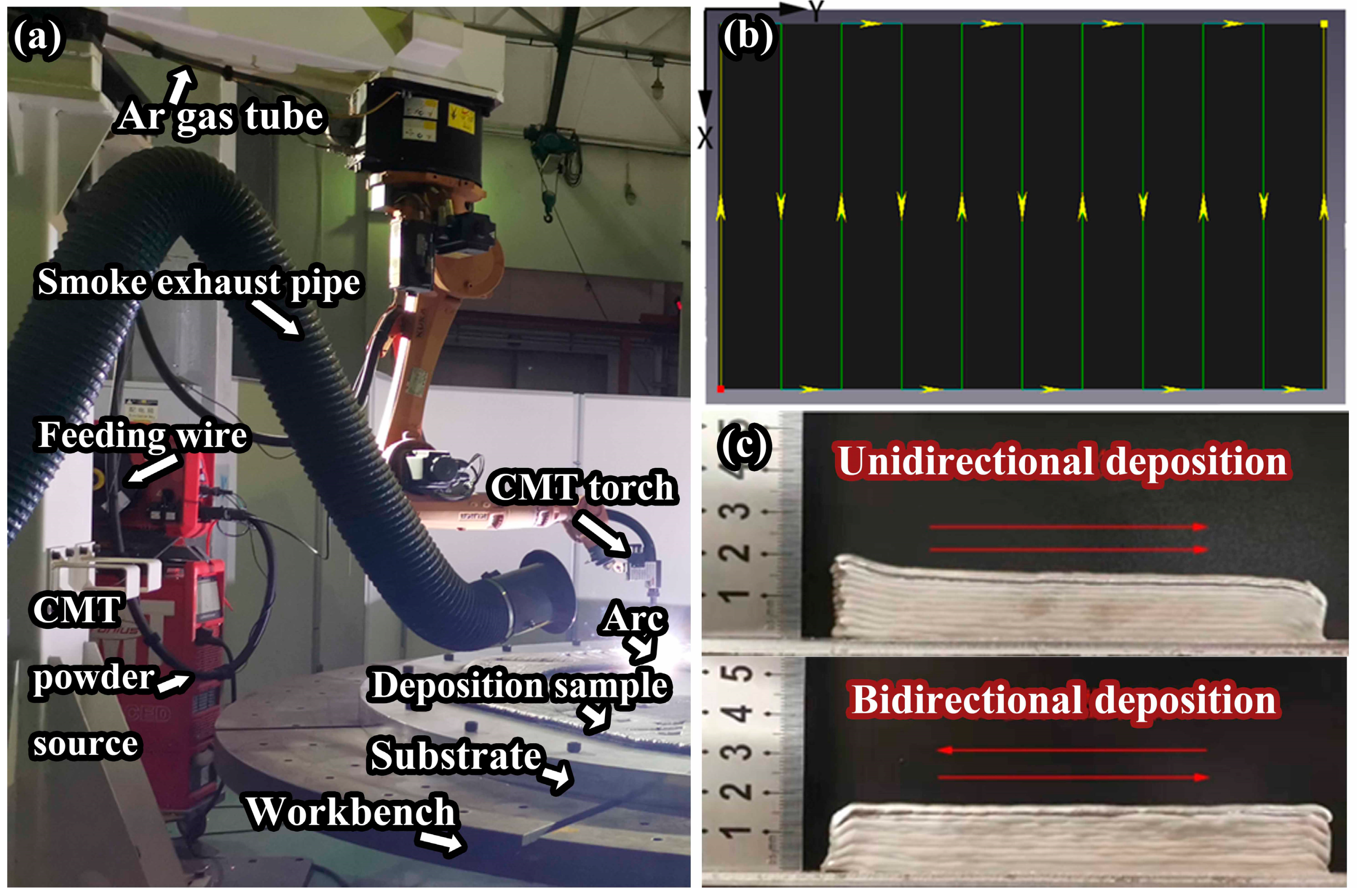
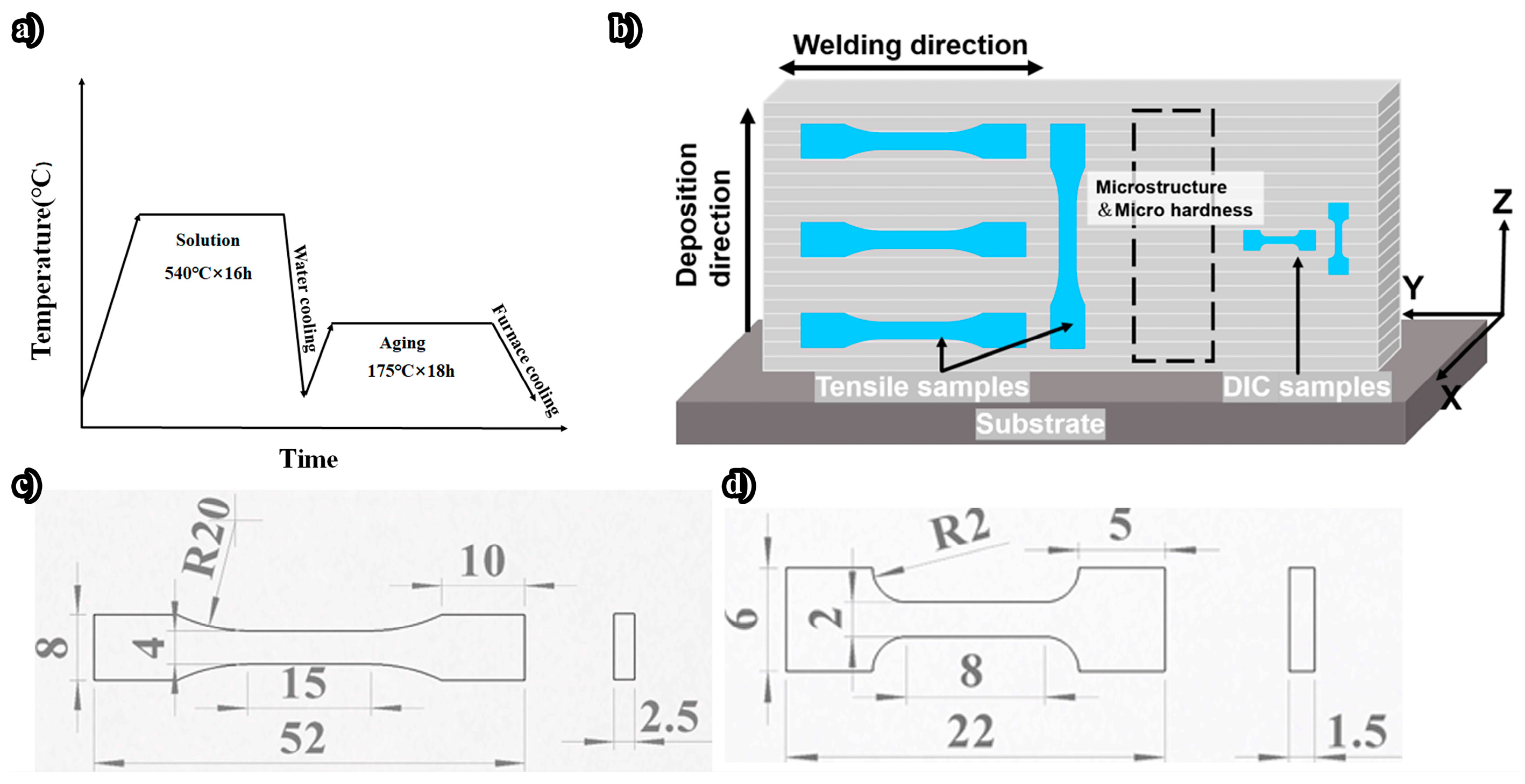
2.2. Methods
3. Results and Discussion
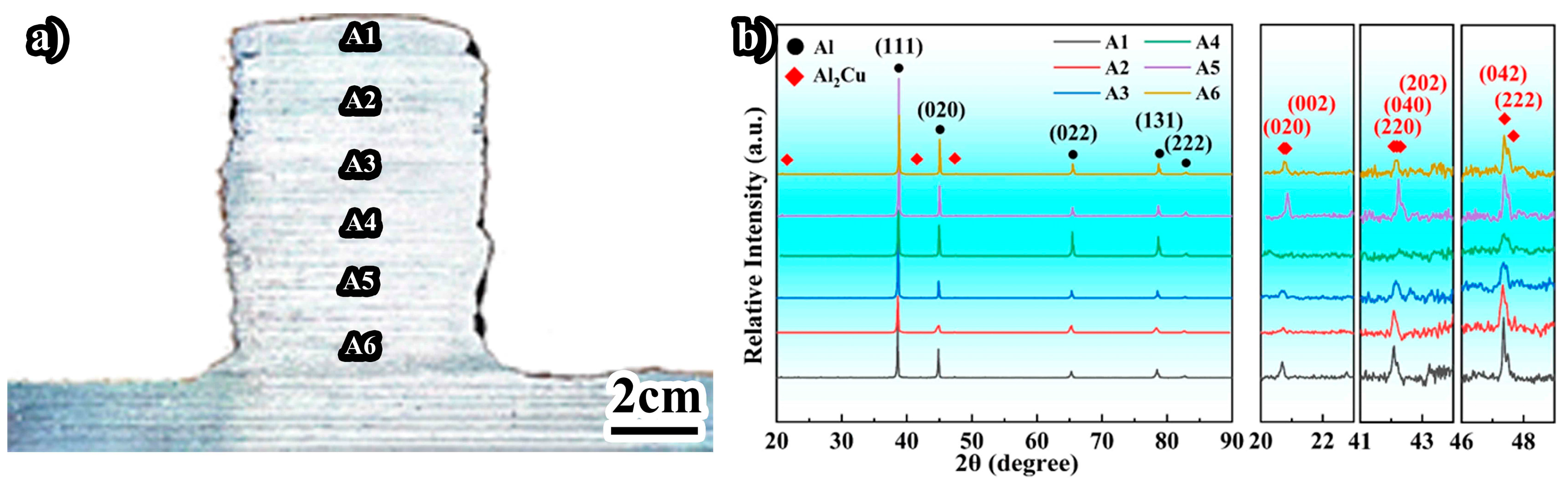
3.1. Microstructure and Porosity
3.2. Mechanical Poperties
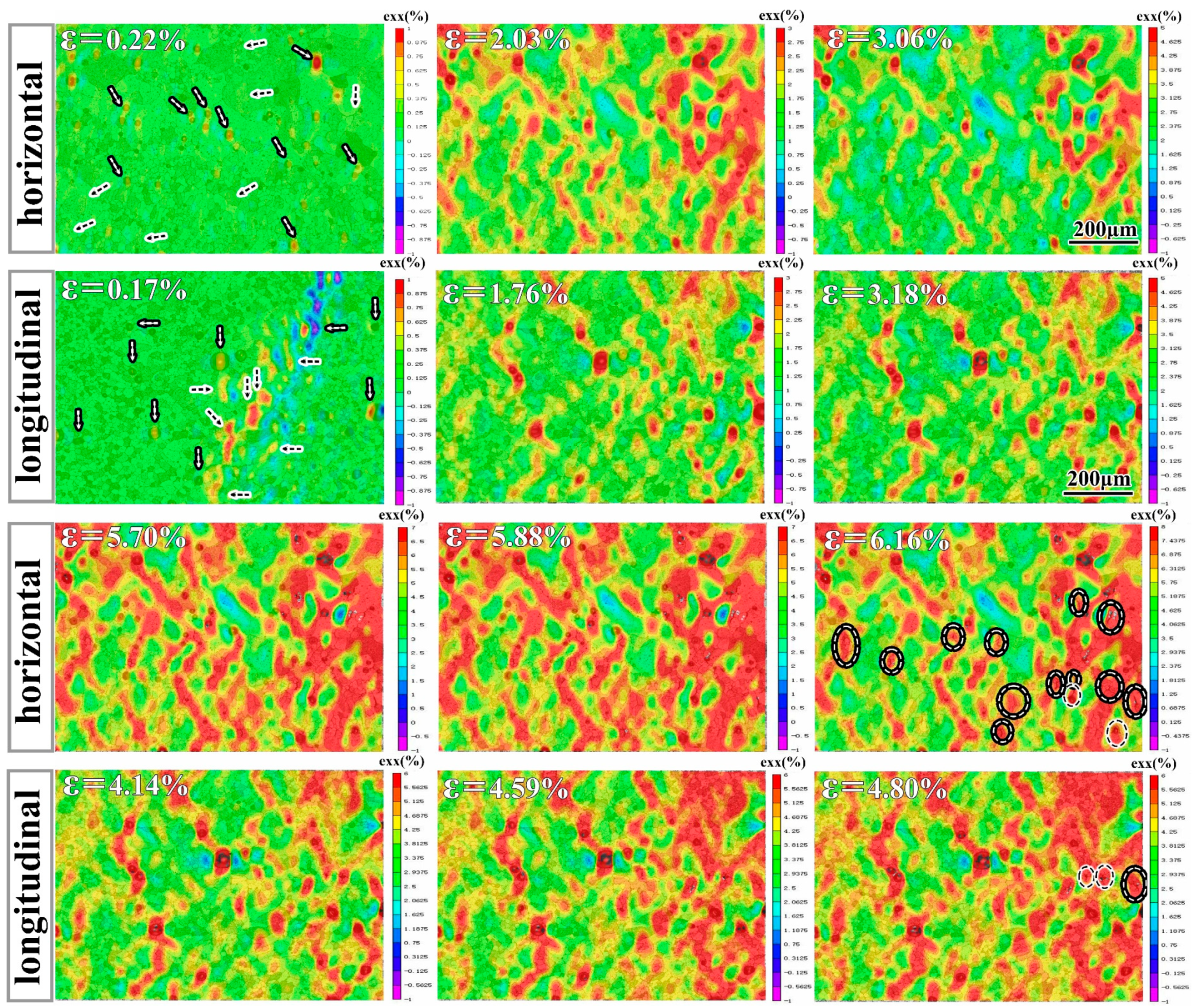
3.2.1. In Situ Micromechanical Test
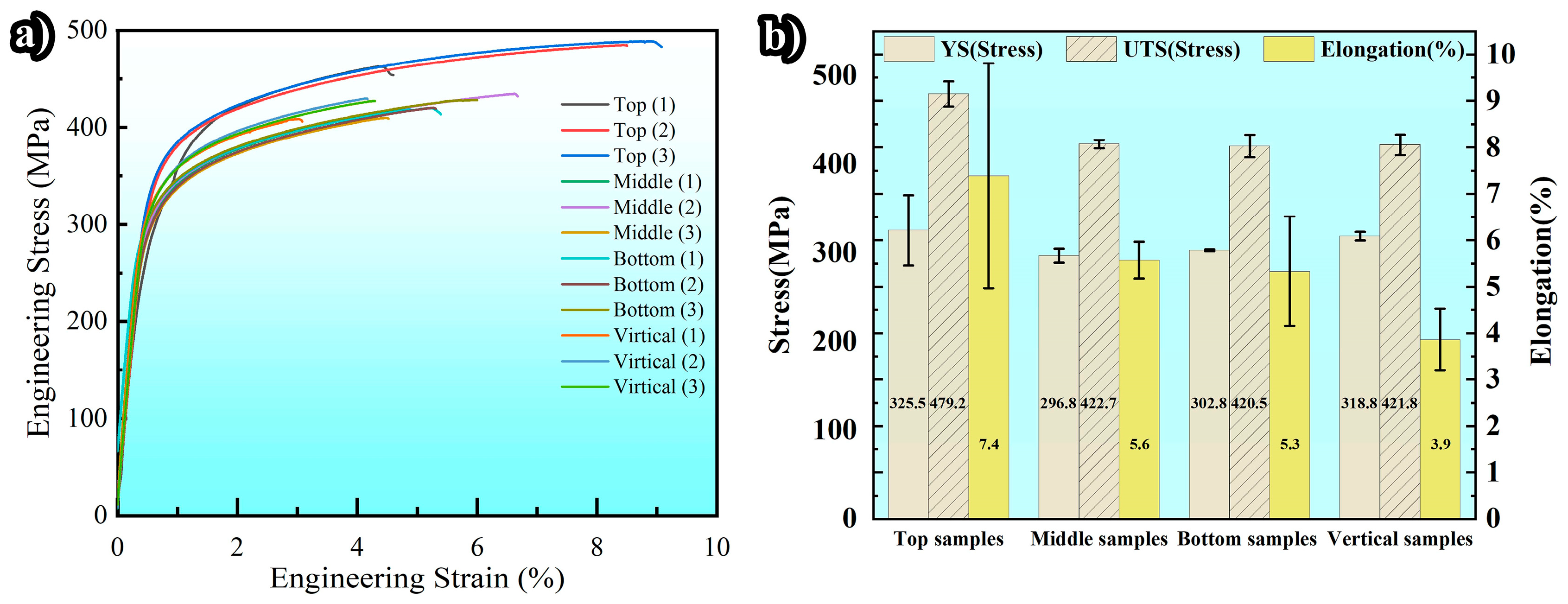
3.2.2. Tensile Properties
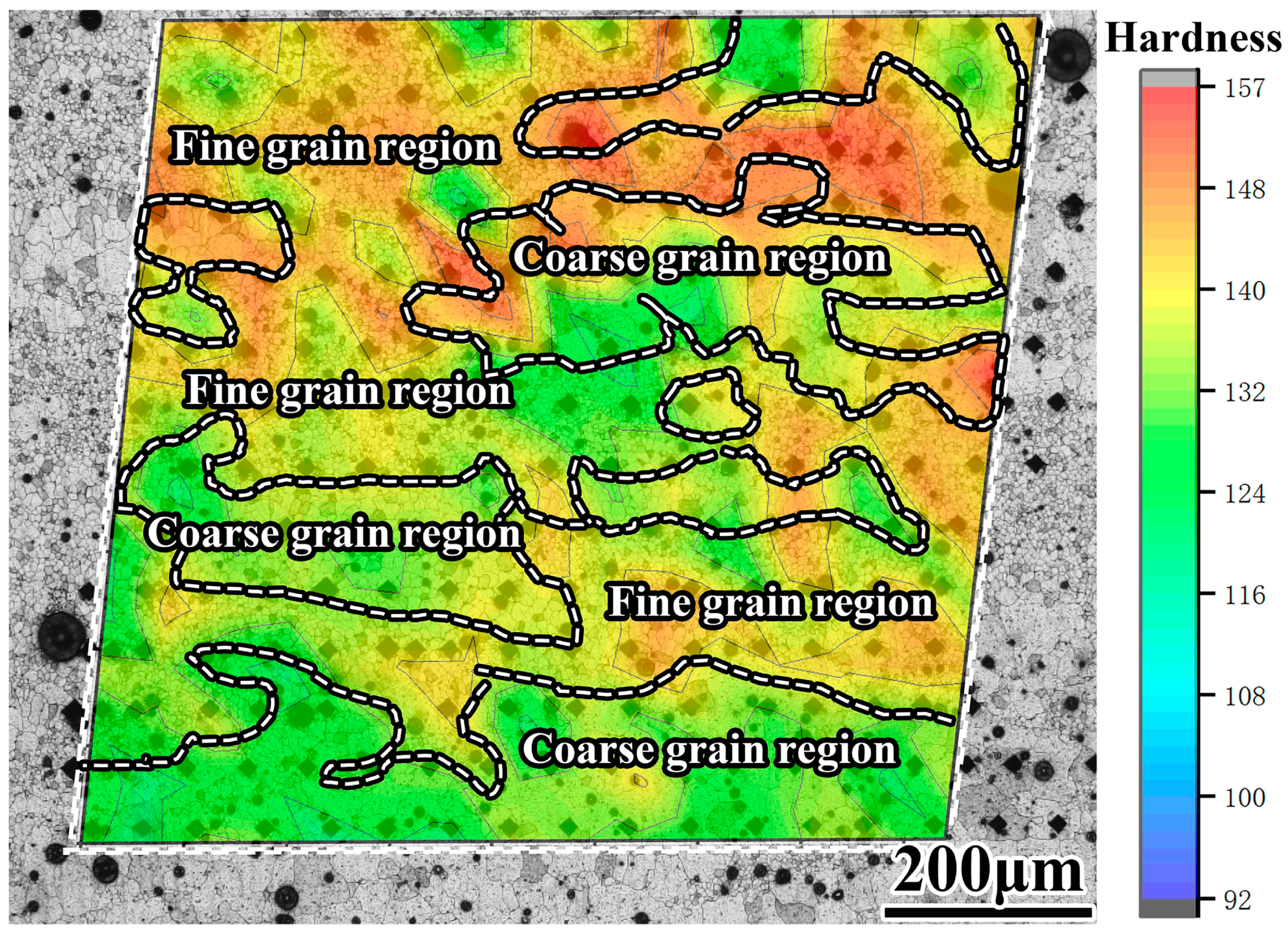
3.2.3. Hardness Test
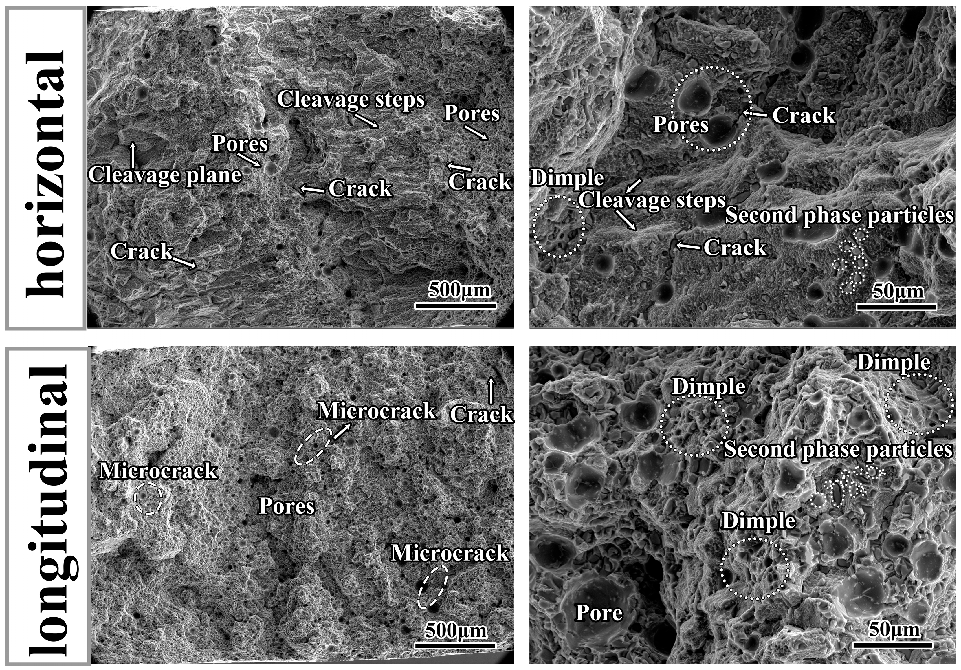
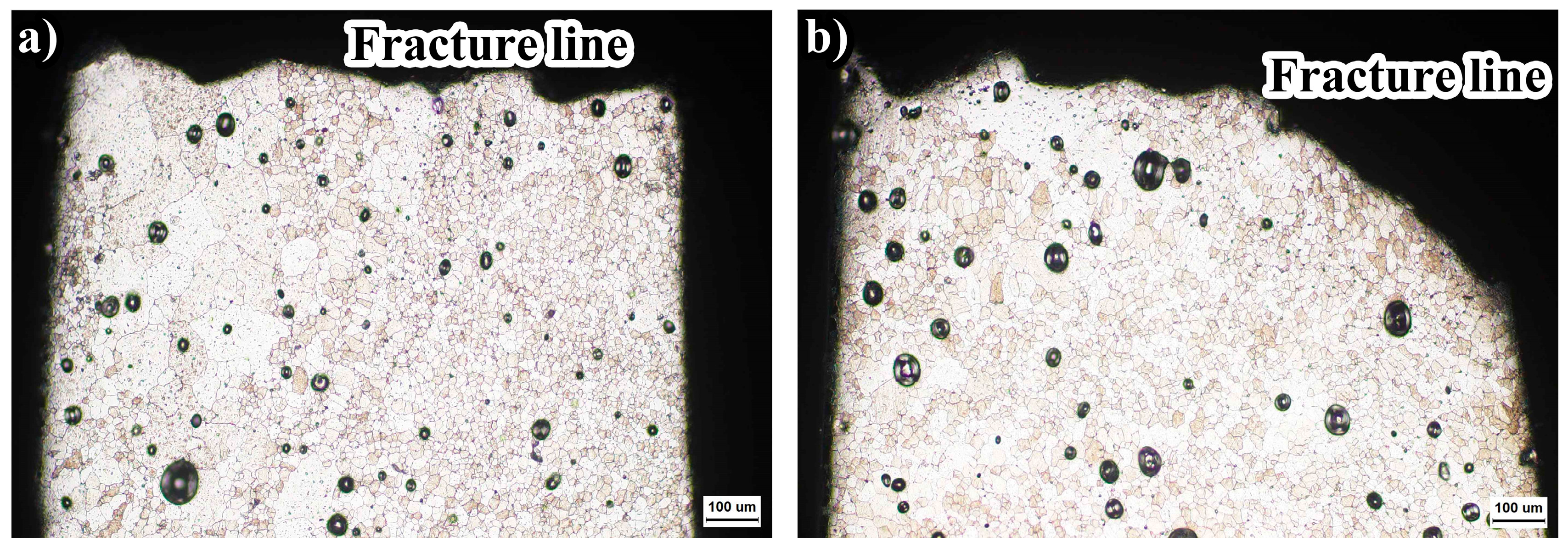
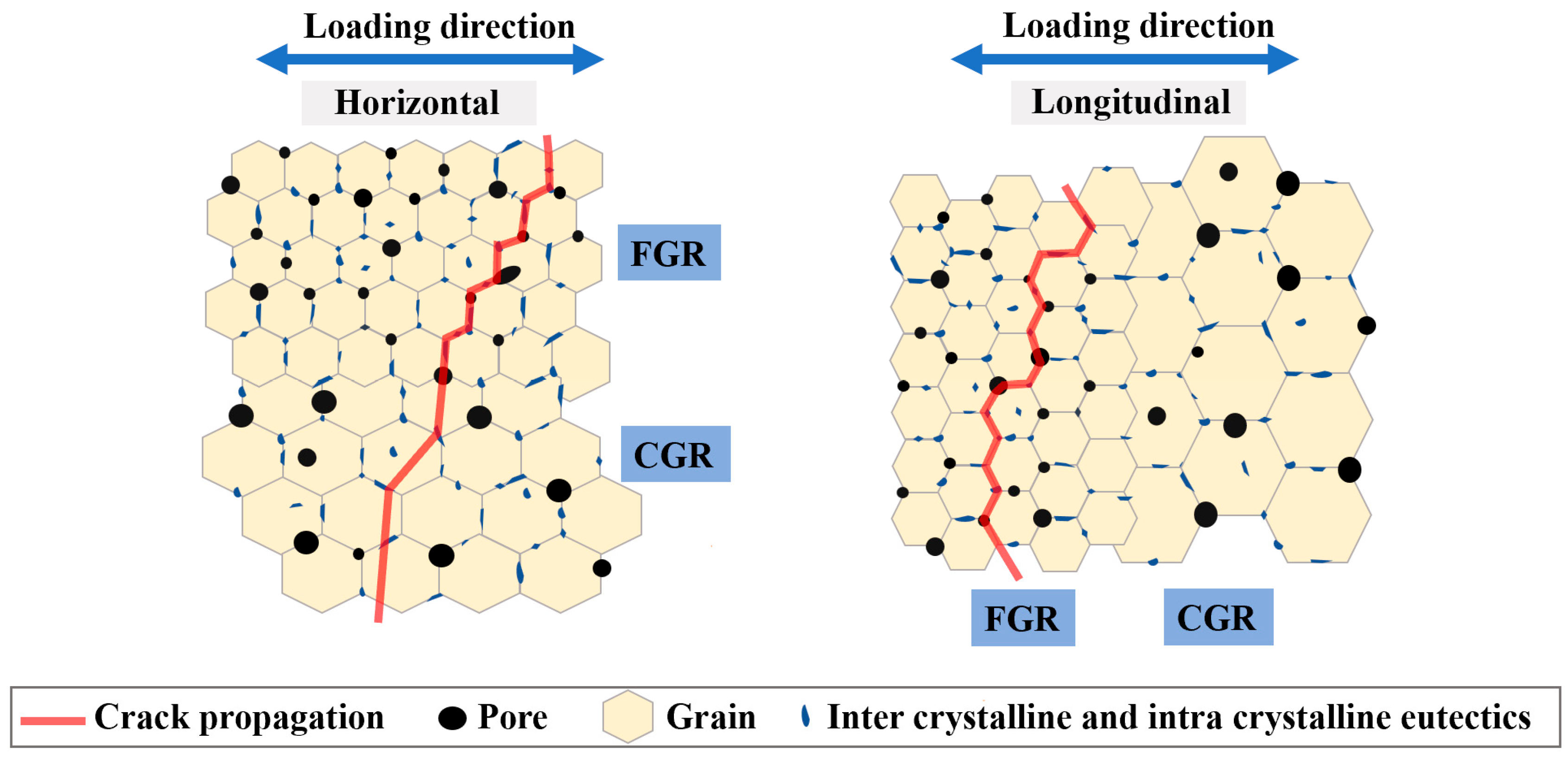
3.2.4. Fracture Analysis
4. Conclusions
- By employing the CMT + PADV mode with a solution treatment of 16 h followed by aging treatment of 18 h, a high-performance 2319 aluminum alloy with a tensile strength of 479.2 MPa, yield strength of 325.5 MPa, and elongation of 7.4% was achieved. These properties are among the highest yield strengths reported in the literature for 2319 aluminum alloy.
- Pores affect the mechanical properties of the prepared 2319 Al alloy, with fewer pores in the top layer exhibiting the best mechanical performance. Additionally, the accumulation of fine pores in equiaxed grain regions leads to different deformation mechanisms and failure modes in longitudinal and horizontal directions. Further reduction in porosity is advantageous for improving the mechanical properties of longitudinal specimens.
- In fine grain layers, cracks initiate at brittle second-phase particles and propagate along the grain boundaries intersecting with the second phase. Encounters with pores along the grain boundaries accelerate the overall failure of the material. In coarse grain layers, cracks directly penetrate through the grains.
Supplementary Materials
Author Contributions
Funding
Data Availability Statement
Acknowledgments
Conflicts of Interest
References
- Fan, H.; Hu, J.; Wang, Y. A review of laser additive manufacturing (LAM) aluminum alloys: Methods, microstructures and mechanical properties. Opt. Laser Technol. 2024, 175, 110722. [Google Scholar] [CrossRef]
- Dixit, S.; Liu, S. Laser Additive Manufacturing of High Strength Aluminum Alloys Challenges and Strategies. J. Manuf. Mater. Process. 2022, 6, 156. [Google Scholar] [CrossRef]
- Montanari, R.; Palombi, A.; Richetta, M. Additive Manufacturing of Aluminum Alloys for Aeronautic Applications: Advantages and Problems. Metals 2023, 13, 716. [Google Scholar] [CrossRef]
- Blakey-Milner, B.; Gradl, P.; Snedden, G. Metal additive manufacturing in aerospace: A review. Mater. Des. 2021, 209, 110008. [Google Scholar] [CrossRef]
- Harshita, P.; Anisha, A.; Sutha, G.G. Applications of wire arc additive manufacturing (WAAM) for aerospace component manufacturing. Int. J. Adv. Manuf. Technol. 2023, 127, 4995–5011. [Google Scholar]
- Debroy, T.; Wei, H.L.; Zuback, J.S. Additive manufacturing of metallic components—Process, structure and properties. Prog. Mater. Sci. 2018, 92, 112–224. [Google Scholar] [CrossRef]
- Svetlizky, D.; Das, M.; Zheng, B. Directed energy deposition (DED) additive manufacturing: Physical characteristics, defects, challenges and applications. Mater. Today 2021, 49, 271–295. [Google Scholar] [CrossRef]
- Svetlizky, D.; Zheng, B.; Vyatskikh, A. Laser-based directed energy deposition (DED-LB) of advanced materials. Mater. Sci. Eng. A 2022, 840, 142967. [Google Scholar] [CrossRef]
- Martina, F.; Williams, S.W. Wire+arc additive manufacturing vs. traditional machining from solid: A cost comparison. Mater. Sci. Technol. 2015, 32, 27. [Google Scholar]
- Köhler, M.; Fiebig, S.; Hensel, J. Wire and Arc Additive Manufacturing of Aluminum Components. Metals 2019, 9, 608. [Google Scholar] [CrossRef]
- Tabernero, I.; Paskual, A.; Álvarez, P. Ivántabernero; Paskual, A.; Álvarez, P. Study on Arc Welding Processes for High Deposition Rate Additive Manufacturing. Procedia CIRP 2018, 68, 358–362. [Google Scholar]
- Liu, D.; Wu, D.; Wang, R. Formation mechanism of Al-Zn-Mg-Cu alloy fabricated by laser-arc hybrid additive manufacturing: Microstructure evaluation and mechanical properties. Addit. Manuf. 2022, 50, 102554. [Google Scholar] [CrossRef]
- Zhang, L.; Wang, S.; Wang, H. Mechanical properties and microstructure revolution of vibration assisted wire arc additive manufacturing 2319 aluminum alloy. Mater. Sci. Eng. A 2023, 885, 145634. [Google Scholar] [CrossRef]
- Wang, Z.; Lin, X.; Wang, L. Microstructure evolution and mechanical properties of the wire + arc additive manufacturing Al-Cu alloy. Addit. Manuf. 2021, 47, 102298. [Google Scholar] [CrossRef]
- Lopez, M.A.; Ukar, E.; Rodriguez, I. Influence of Deposition Strategy and Heat Treatment on Mechanical Properties and Microstructure of 2319 Aluminium Waam Components. Mater. Des. 2022, 221, 110974. [Google Scholar]
- Guo, Y.; Han, Q.; Hu, J. Comparative Study on Wire-Arc Additive Manufacturing and Conventional Casting of Al–Si Alloys: Porosity, Microstructure and Mechanical Property. Acta Metall. Sin. (Engl. Lett.) 2022, 35, 475–485. [Google Scholar] [CrossRef]
- Cong, B.; Ding, J.; Williams, S. Effect of arc mode in cold metal transfer process on porosity of additively manufactured Al-6.3%Cu alloy. Int. J. Adv. Manuf. Technol. 2015, 76, 1593–1606. [Google Scholar] [CrossRef]
- Cui, J.; Commins, P.; He, F. WAAM process for metal block structure parts based on Mixed Heat Input. Int. J. Adv. Manuf. Technol. 2021, 113, 503–521. [Google Scholar] [CrossRef]
- Fang, X.; Zhang, L.; Chen, G. Microstructure evolution of wire-arc additively manufactured 2319 aluminum alloy with interlayer hammering. Mater. Sci. Eng. A 2021, 800, 140168. [Google Scholar] [CrossRef]
- Gu, J.; Ding, J.; Williams, S.W. The effect of inter-layer cold working and post-deposition heat treatment on porosity in additively manufactured aluminum alloys. J. Mater. Process. Technol. 2016, 230, 26–34. [Google Scholar] [CrossRef]
- Li, R.; Wang, R.; Zhou, X. Microstructure and mechanical properties of 2319 aluminum alloy deposited by laser and cold metal transfer hybrid additive manufacturing. J. Mater. Res. Technol. 2023, 26, 6342–6355. [Google Scholar] [CrossRef]
- Wu, D.; Liu, D.; Niu, F.; Miao, Q.; Zhao, K.; Tang, B.; Bi, G.; Ma, G. Al–Cu alloy fabricated by novel laser-tungsten inert gas hybrid additive manufacturing. Addit. Manuf. 2020, 32, 100954. [Google Scholar] [CrossRef]
- He, H.; Yi, Y.; Huang, S. Effects of thermomechanical treatment on grain refinement, second-phase particle dissolution, and mechanical properties of 2219 Al alloy. J. Mater. Process. Technol. 2020, 278, 116506. [Google Scholar] [CrossRef]
- Derekar, K.S. A review of wire arc additive manufacturing and advances in wire arc additive manufacturing of aluminium. Mater. Sci. Technol. 2018, 34, 895–916. [Google Scholar] [CrossRef]
- Gu, J.; Ding, J.; Williams, S.W. The strengthening effect of inter-layer cold working and post-deposition heat treatment on the additively manufactured Al–6.3Cu alloy. Mater. Sci. Eng. A 2016, 651, 18–26. [Google Scholar] [CrossRef]
- Gu, J.; Gao, M.; Yang, S. Microstructure, defects, and mechanical properties of wire + arc additively manufactured Al Cu4.3-Mg1.5 alloy. Mater. Des. 2019, 186, 108357. [Google Scholar] [CrossRef]
- Mclean, N.; Bermingham, M.J.; Colegrove, P. Effect of Hot Isostatic Pressing and heat treatments on porosity of Wire Arc Additive Manufactured Al 2319. J. Mater. Process. Technol. 2022, 310, 117769. [Google Scholar] [CrossRef]
- GB/T 10858-2023; Wire Electrodes, Wires and Rods for Welding of Aluminium and Aluminium Alloys. China Quality Inspection Press: Beijing, China, 2023.
- ISO 6892-1:2009; Metallic Materials—Tensile testing—Part 1: Method of Test at Room Temperature. International Organization for Standardization (ISO): Geneva, Switzerland, 2009.
- Gu, J.; Gao, M.; Yang, S. Pore formation and evolution in wire + arc additively manufactured 2319 Al alloy. Addit. Manuf. 2019, 30, 100900. [Google Scholar] [CrossRef]
- Hu, S.; Zhang, H.; Wang, Z. The arc characteristics of cold metal transfer welding with AZ31 magnesium alloy wire. J. Manuf. Process. 2016, 24, 298–306. [Google Scholar] [CrossRef]
- Evans, S.I.; Wang, J.; Qin, J. A review of WAAM for steel construction—Manufacturing, material and geometric properties, design, and future directions. Structures 2022, 44, 1506–1522. [Google Scholar] [CrossRef]
- Tian, Y.; Shen, J.; Hu, S. Microstructure and mechanical properties of wire and arc additive manufactured Ti-6Al-4V and AlSi5 dissimilar alloys using cold metal transfer welding. J. Manuf. Process. 2019, 46, 337–344. [Google Scholar] [CrossRef]
- Zhou, Y.; Lin, X.; Kang, N.; Huang, W.; Wang, J.; Wang, Z. Influence of travel speed on microstructure and mechanical properties of wire + arc additively manufactured 2219 aluminum alloy. J. Mater. Sci. Technol. 2020, 37, 143–153. [Google Scholar] [CrossRef]
- Zhou, Y.; Lin, X.; Kang, N. Mechanical properties and precipitation behavior of the heat-treated wire + arc additively manufactured 2219 aluminum alloy. Mater. Charact. 2021, 171, 110735. [Google Scholar] [CrossRef]
- Zhou, Y.; Lin, X.; Kang, N. The heterogeneous band microstructure and mechanical performance in a wire + arc additively manufactured 2219 Al alloy. Addit. Manuf. 2022, 49, 102486. [Google Scholar] [CrossRef]
- Zhou, Y.; Lin, X.; Kang, N. Hot deformation induced microstructural evolution in local-heterogeneous wire + arc additive manufactured 2219 Al alloy. J. Alloys Compd. 2021, 865, 158949. [Google Scholar] [CrossRef]
- Dai, G.; Xue, M.; Guo, Y. Gradient microstructure and strength-ductility synergy improvement of 2319 aluminum alloys by hybrid additive manufacturing. J. Alloys Compd. 2023, 968, 171781. [Google Scholar] [CrossRef]
- Chang, T.; Fang, X.; Liu, G. Wire and arc additive manufacturing of dissimilar 2319 and 5B06 aluminum alloys. J. Mater. Sci. Technol. 2022, 124, 65–75. [Google Scholar] [CrossRef]
- Sun, R.; Li, L.; Zhu, Y. Microstructure, residual stress and tensile properties control of wire-arc additive manufactured 2319 aluminum alloy with laser shock peening. J. Alloys 2018, 747, 255–265. [Google Scholar] [CrossRef]
- Eimer, E.; Williams, S.; Ding, J. Mechanical performances of the interface between the substrate and deposited material in aluminium wire Direct Energy Deposition. Mater. Des. 2023, 225, 111594. [Google Scholar] [CrossRef]
- Anderson-Wedge, K.; Avery, D.Z.; Daniewicz, S.R. Characterization of the fatigue behavior of additive friction stir-deposition AA2219. Int. J. Fatigue 2021, 142, 105951. [Google Scholar] [CrossRef]
- Gu, J.; Wang, X.; Bai, J. Deformation microstructures and strengthening mechanisms for the wire+arc additively manufactured Al-Mg4.5Mn alloy with inter-layer rolling. Mater. Sci. Eng. A 2018, 712, 292–301. [Google Scholar]
- Guo, W.; Yi, Y.; Huang, S. Effect of warm-rolling temperature on the microstructural evolution and mechanical properties of large 2219 Al-Cu alloy rings. Mater. Today Commun. 2023, 36, 106702. [Google Scholar] [CrossRef]
- Xiao, H.; Zhang, C.; Zhu, H. Effect of direct aging and annealing on the microstructure and mechanical properties of AlSi10Mg fabricated by selective laser melting. Rapid Prototyp. J. 2023, 29, 118–127. [Google Scholar] [CrossRef]
- Huang, C.; Kou, S. Partially melted zone in aluminum welds: Solute segregation and mechanical behavior. Weld. J. 2001, 80, 9–17. [Google Scholar]
- Yang, J.; Ni, Y.; Li, H. Heat Treatment Optimization of 2219 Aluminum Alloy Fabricated by Wire-Arc Additive Manufacturing. Coatings 2023, 13, 610. [Google Scholar] [CrossRef]


| Cu | Mn | Zr | Ti | Fe | Zn | Si | V | Al |
|---|---|---|---|---|---|---|---|---|
| 6.54 | 0.31 | 0.16 | 0.14 | 0.09 | 0.07 | 0.04 | 0.03 | Bal. |
| Process Parameters | Value |
|---|---|
| Type | CMT-PADV |
| Wire feeding speed | 6.5 m/min |
| Travel speed | 9 mm/s |
| EP/EN balance | 3.0 |
| Argon | 99.99% purity |
| Protective gas flow | 25 L/min |
| Arc length correction | 3% |
| Wire extension | 15 mm |
| Sample Position | YS (MPa) | UTS (MPa) | EL (%) |
|---|---|---|---|
| Top | 325.5 ± 39.5 | 479.2 ± 14.2 | 7.4 ± 2.4 |
| Middle | 296.8 ± 7.8 | 422.7 ± 4.7 | 5.6 ± 0.4 |
| Bottom | 302.8 ± 1.0 | 420.5 ± 12.7 | 5.3 ± 1.2 |
| Vertical | 318.8 ± 4.8 | 421.8 ± 11.5 | 3.9 ± 0.7 |
Disclaimer/Publisher’s Note: The statements, opinions and data contained in all publications are solely those of the individual author(s) and contributor(s) and not of MDPI and/or the editor(s). MDPI and/or the editor(s) disclaim responsibility for any injury to people or property resulting from any ideas, methods, instructions or products referred to in the content. |
© 2024 by the authors. Licensee MDPI, Basel, Switzerland. This article is an open access article distributed under the terms and conditions of the Creative Commons Attribution (CC BY) license (https://creativecommons.org/licenses/by/4.0/).
Share and Cite
Pan, Y.; Yu, M.; Xu, C.; Zhang, J.; Geng, L. High-Performance 2319 Aluminum Alloy via CMT-WAAM: Microstructure, Porosity, and Mechanical Properties. Metals 2024, 14, 797. https://doi.org/10.3390/met14070797
Pan Y, Yu M, Xu C, Zhang J, Geng L. High-Performance 2319 Aluminum Alloy via CMT-WAAM: Microstructure, Porosity, and Mechanical Properties. Metals. 2024; 14(7):797. https://doi.org/10.3390/met14070797
Chicago/Turabian StylePan, Yuxin, Ming Yu, Chao Xu, Jianchao Zhang, and Lin Geng. 2024. "High-Performance 2319 Aluminum Alloy via CMT-WAAM: Microstructure, Porosity, and Mechanical Properties" Metals 14, no. 7: 797. https://doi.org/10.3390/met14070797
APA StylePan, Y., Yu, M., Xu, C., Zhang, J., & Geng, L. (2024). High-Performance 2319 Aluminum Alloy via CMT-WAAM: Microstructure, Porosity, and Mechanical Properties. Metals, 14(7), 797. https://doi.org/10.3390/met14070797