Communication

A Comparative Analysis of a Microstructure and Properties for Monel K500 Hot-Rolled to a Round Bar and Wire Deposited on a Round Surface

1
Centre for Microscopy and Microanalysis, The University of Queensland, Brisbane, QLD 4072, Australia
2
School of Mechanical, Materials, Mechatronics and Biomedical Engineering, University of Wollongong, Northfields Avenue, Wollongong, NSW 2522, Australia
*
Author to whom correspondence should be addressed.
Metals 2024, 14(7), 813; https://doi.org/10.3390/met14070813
Submission received: 23 May 2024 / Revised: 27 June 2024 / Accepted: 11 July 2024 / Published: 13 July 2024
(This article belongs to the Section Additive Manufacturing)

Abstract

:
Metal manufacturing processes based on deformation (forging, rolling) result in a fine grain structure with a complex dislocation substructure, which positively influence mechanical properties. Casting and additive manufacturing (powder- or wire-based) usually produce a coarse grain structure with a poorly developed dislocation substructure, which negatively affect mechanical properties. Heat treatment may alter phase balance and stimulate precipitation strengthening; however, precipitation kinetics depends on the dislocation substructure. In this paper, a comparative study of the microstructure and strength is presented for Monel K500 alloy containing 63 Ni, 30 Cu, 2.0 Mn, and 2.0 Fe (wt.%), and microalloyed with Al, Ti, and C hot-rolled to a round bar and deposited on a round surface using wire additive manufacturing (WAAM) technology. An increased dislocation density and number density of fine precipitates resulted in 8–25% higher hardness and 1.8–2.6 times higher compression yield stress in the hot-rolled alloy compared to these in the WAAM-produced alloy. However, due to a high work hardening rate, only 3–10% cold deformation was necessary to increase the strength of the WAAM alloy to this of the hot-rolled one. Age hardening heat treatment, through the intensification of the precipitation strengthening mechanism, reduced the value of cold deformation strain required to equalise the properties. Based on the obtained results, a new technology consisting of additive manufacturing, heat treatment, and cold deformation can be proposed. It can produce WAAM components with strength and hardness improved to the level of hot-rolled components, which is a significant development of additive manufacturing.

1. Introduction

Wire arc additive manufacturing (WAAM) is a rapidly developing process for the fabrication of machine components. Recent publications reported the successful application of WAAM for making parts from alloys based on Ti, Fe, Al, Cu, Mg, Ni-Cr, and Ni-Ti [1,2,3,4,5,6,7,8,9,10,11,12,13,14,15,16,17,18,19,20]. WAAM of Ni-Cu alloys has been previously reported in our publications [21,22]. In spite of significant technological progress in WAAM of several alloy groups, the chemistry–microstructure–properties relationship is not fully understood. This inspires further investigations.
Reliability and lifetime of machinery depends on mechanical properties of their parts, such as hardness, strength, and toughness. Therefore, the fabrication process should guarantee the required properties’ level. Traditional metal manufacturing processes based on hot and cold deformation (forging, rolling) result in development of a fine grain structure with a complex dislocation substructure. These positively influence mechanical properties via strong grain boundary and dislocation strengthening mechanisms. However, casting and additive manufacturing (powder- or wire-based) usually produce a coarse grain structure with a poorly developed dislocation substructure. These negatively affect mechanical properties. Heat treatment is widely applied to improve strength and toughness via altering phase balance and stimulating precipitation strengthening. These two mechanisms may compensate for a weak grain boundary and dislocation strengthening inherent to additively manufactured metals. However, precipitation kinetics depends on the dislocation substructure. In particular, a decrease in dislocation density is expected to slow down the particle precipitation [23,24,25], which would result in lower precipitate number density and strength. Therefore, further growth of the industrial application of additive manufacturing requires understanding of microstructure–properties relationships, in particular the level of contribution to mechanical properties from various strengthening mechanisms. This knowledge would be used for the optimisation of processing technologies containing an additive manufacturing stage.
In this paper, the microstructure and mechanical properties are studied for Monel K500 alloy deposited on a round surface (40 mm diameter bar), in contrast to our previous works where we studied deposition on a plate. The shape of the base metal will affect the cooling rate during the solidification of the melt pool, and, therefore, will produce a different set of microstructural parameters. Although the cooling rate during solidification was not measured, our characterisation results show a variation in the microstructural parameters with the shape of base metal: the secondary dendrite arm spacing (SDAS) and sizes of coarse particles were half the size after deposition on a plate (SDAS was 4–9 μm and coarse particle average size range was 0.33–0.45 μm [21]) compared to these after deposition on a round bar (SDAS is 13 μm and coarse particle average size is 0.7 μm in Table 1 in this paper). This may indicate a slower cooling rate after deposition on a round bar and longer times at elevated temperatures, leading to the particle growth.
Monel K500 contains 63 Ni-30 Cu-2.0 Mn-2.0 Fe-AlTiC (wt.%). High copper additions improve corrosion resistance of Ni in many agents. Additions of Al, Ti, and C provide precipitation strengthening by γ′-Ni3AlX (where X can be Cu, Mn, Ti, or Si), Ni3Ti, NiFe3 (AlFe), and TiC particles [26]. A unique properties combination of NiCu alloys is widely utilised in (i) machine components for chemical and nuclear industries [27,28] and marine [29,30,31,32,33,34] and high-temperature equipment (gas turbines, missiles, aerospace) [28,35,36]; (ii) electrodes in fuel cells [37]; (iii) hydrogen generation [38,39,40], and (iv) corrosion resisting coatings [41,42]. For load bearing applications, rolled or forged microstructures are preferred. Applicability of the additively produced microstructures in the areas where deformed ones are usually used remains a question, because additively produced alloys may show reduced strength. However, mechanical properties can be improved with post processing heat treatment. Therefore, in this work, we studied the effect of heat treatment with respect to both microstructure types, hot-rolled and additively produced. This study allowed us to propose a new technology based on wire arc additive manufacturing followed by heat treatment and cold deformation. This technology has a potential to produce additively manufactured components with strength and hardness similar to these of the hot-rolled alloys, which is not the case at the moment.

2. Materials and Experimental Techniques

Two materials were comparatively studied in this paper: (1) the weld deposition of a 1.0 mm diameter wire containing 68.8 Ni-3.0 Al-0.5 Ti-1.29 Fe-0.8 Mn-0.17 Si-0.088 C-bal. Cu (wt.%) and (2) a 40 mm hot-rolled rod containing 63.57 Ni-3.32 Al-0.70 Ti-0.75 Fe-0.75 Mn-0.25 Si-0.09 C-bal Cu (wt.%). Both compositions correspond to the Monel K500 alloy. The chemical composition of both the deposition and rod were measured using an optical emission spectroscopy system manufactured by Oxford Instruments (Abingdon, UK). At least seven points were measured for each material. The first three points have not been taken into consideration as they were used for the gun warm up and recalibration.
The deposition of the wire on the rod was carried out by cold metal transfer technology using an ABB 1400 robot with a Fronius welder (manufactured by Fronius International, Weis, Austria) covering the whole rod circumference on the length of 20 cm. The deposited layer thickness was ~5 mm (Figure 1). The following welding parameters were used: torch travel speed of 200 mm/min, average current value of 153 A, and average voltage of 14.8 V; the resulting average heat input was 679 J/mm. After deposition, 3 mm thick discs were cut perpendicular to the longitudinal axis of the rod to investigate the microstructure–properties relationship. The discs cut after deposition were subjected to the post-weld heat treatment according to the standard industrial practise. Both the hot-rolled and WAAM processed samples were subjected to the same heat treatment schedule; for a guaranty, the samples were put in the furnace simultaneously. The following two conditions were studied, in addition to the as-received/as-welded ones: (i) annealed at 1100 °C for 15 min and age-hardened at 610 °C for 8 h in vacuum and air-cooled to room temperature; and (ii) age-hardened at 610 °C for 8 h in vacuum without prior annealing, and then air-cooled to room temperature.
Microhardness was measured on the cross-section disc specimens cut from the rod after deposition (Figure 1). Microhardness maps covering hot-rolled and weld-deposited areas were acquired on a Struers DuraScan Vickers hardness tester with 0.5 kg load. About 250 indentations were performed for each map; one map was acquired for each heat treatment condition. The indentations were performed at a distance of approximately five times the length of the indent diagonals to ensure that the results were not contaminated by work hardening from previous indentations. The indentation dwell time was 14 s.
Compression testing was carried out on a Kammrath and Weiss GmbH mini-tensile stage (Kammrath and Weiss GmbH, Dortmund, Germany). The testing was performed using cylindrical specimens of a 3 mm diameter and 4 mm height cut on a wire cutting machine. Industrial-grade grease was applied on top and bottom surfaces of the cylinders to minimise friction between the specimens and the machine traverses; this had to guarantee unidirectional deformation during testing. The constant crosshead speed of 4 mm·s−1 was applied and resulted in a 1 × 10⁻³ s−1 initial strain rate. Two specimens were tested for each of the six studied conditions.
Sample preparation for optical and scanning electron microscopy was carried out using standard metallographic techniques including mounting in Polyfast resin, polishing on a Struers Tegramin-25 automatic polisher to a 1 μm finish, and etching with a ferric chloride solution. Optical microscopy was carried out using a Leica DM 6000 M optical microscope (manufactured by Leica Microsystems, Wetzlar, Germany) equipped with Leica Application Suite (LAS) 4.0.0 image processing software. More than 400 dendrite arms (for the weld-deposited areas) and grains (for hot-rolled rod) were measured for each heat treatment condition to determine average secondary dendrite arm spacing and grain size. Scanning electron microscopy was conducted using a JEOL7001F FEG scanning electron microscope (SEM) (manufactured by JEOL Ltd., Tokyo, Japan) operating at 15 kV. The energy dispersive X-ray spectroscopy (EDS) of precipitates was carried out using an AZtec 2.0 Oxford SEM EDS system (manufactured by Oxford Instruments, Abingdon, UK). Particle compositions were analysed on up to 60 particles for each condition. More than 200 particles were manually measured for each condition to determine the particle size distributions.
Transmission electron microscopy was conducted using JEOL JEM-2011 (manufactured by JEOL Ltd., Tokyo, Japan) operating at 200 kV. For the determination of <20 nm particle size and number density values, up to 600 particles have been measured for each studied condition. Particle types were analysed using the selected area diffraction technique. The dislocation imaging was conducted near the [101] grain zone axis.

3. Results

3.1. Hardness and Strength

The microhardness maps and compression stress–strain curves are presented in Figure 2 and Figure 3, respectively. The microhardness in the deposition was measured to be
  • In the range of 140–170 HV (the difference between maximum and minimum Δ = 30) with the average value of 153 HV in the as-welded condition;
  • In the range of 230–316 HV (Δ = 86) with the average value of 263 HV in the aged condition;
  • In the range of 203–275 HV (Δ = 72) with the average value of 238 HV in the annealed and aged condition; and this in the hot-rolled rod was measured to be
  • In the range of 175–206 HV (Δ = 31) with the average value of 191 HV in the as-received condition;
  • In the range of 274–294 HV (Δ = 20) with the average value of 285 HV in the aged condition;
  • In the range of 269–294 HV (Δ = 25) with the average value of 276 HV in the annealed and aged condition.
Figure 2. (ac) Optical images of indentations and (df) hardness maps for (a,d) as-welded, (b,e) aged, and (c,f) annealed and aged conditions.
Metals 14 00813 g002
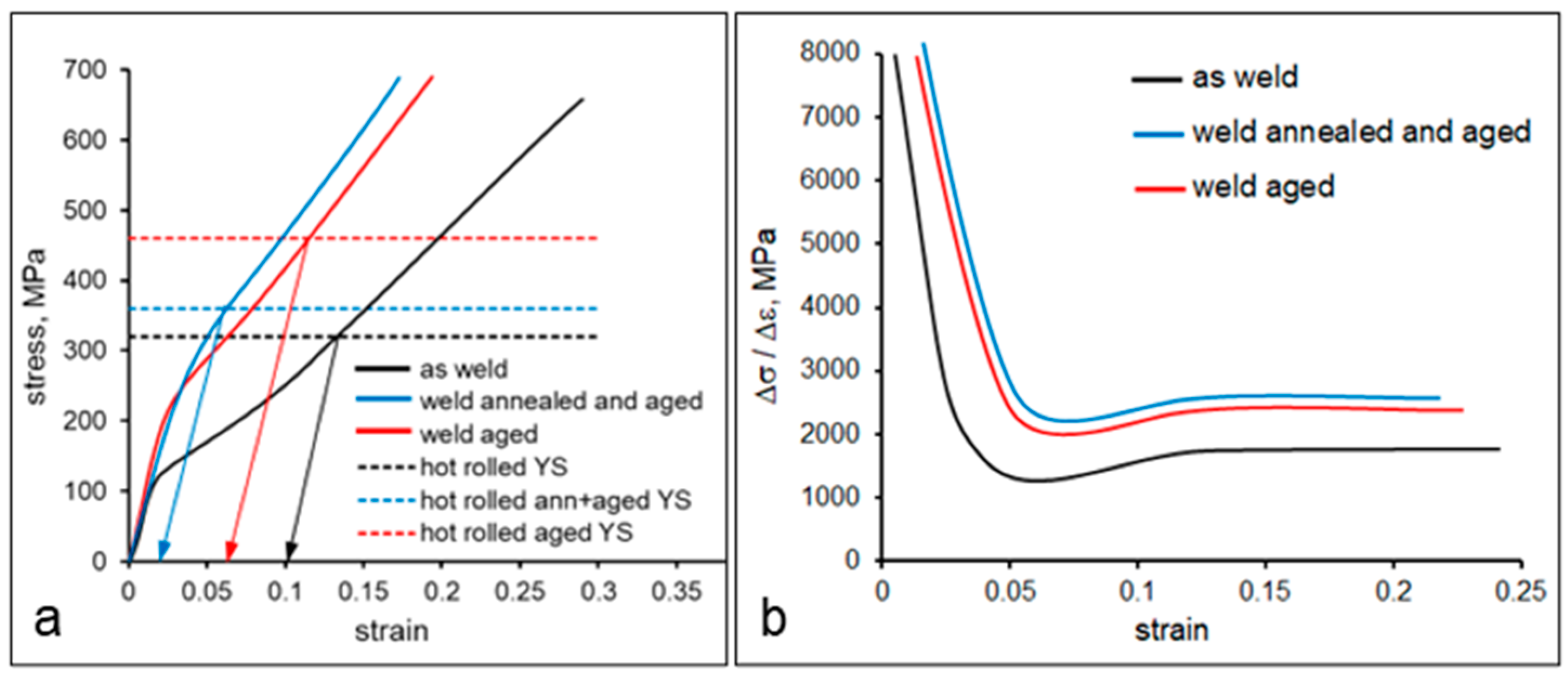
Figure 3. (a) Average engineering compression stress–strain curves for the weld deposition with YS values for the hot-rolled material, and (b) the work hardening rate for the three studied weld conditions.
Metals 14 00813 g003
Hardness of the hot-rolled alloy was 20–40 HV higher than this of the weld deposition (depending on heat treatment). In both material conditions (rolled and deposited), the hardness increased after ageing without prior annealing to a greater extent than this after ageing following annealing. Hardness mapping showed a similar hardness range value of 30 HV between the maximum and minimum values for the hot-rolled and weld-deposited conditions. However, the variation in the hardness range with heat treatment varied for hot-rolled and deposited materials: for the weld deposition, the hardness range increased (to 86 and 72 HV for the aged and annealed and aged conditions, respectively), and for the hot-rolled bar, the hardness range decreased (to 20 and 25 HV for the aged and annealed and aged conditions, respectively). This indicates the homogenization of the microstructure with heat treatment in the hot-rolled rod, and development of a less homogeneous microstructure in the weld deposition.
The compression yield stress in the weld deposition was measured to be
  • 120 ± 10 MPa in the as-welded condition;
  • 220 ± 14 MPa in the aged condition;
  • 200 ± 12 MPa in the annealed and aged condition; and this in the hot-rolled rod was measured to be
  • 320 ± 10 MPa in the as-received hot-rolled condition;
  • 470 ± 15 MPa in the aged condition;
  • 360 ± 12 MPa after annealing followed by ageing.
The yield stress of hot-rolled alloy was 1.8–2.6 times higher than this of the weld deposition (depending on heat treatment). In both material conditions (rolled and deposited), the yield stress increased after ageing without prior annealing to a greater extent than this after ageing following annealing. In spite of the yield stress value being higher for the aged deposition compared to the annealed and aged one (Figure 3a), the work hardening rate was higher for the annealed and aged deposition (Figure 3b). An overall high work hardening rate of the weld-deposited alloy resulted in fast growth of the flow stress during compression testing. Thus, only minor cold deformation strains were required for the yield stress in weld deposition to reach similar values that were measured in the hot-rolled alloy (plastic component in Figure 3a): 0.10 strain for the as-welded condition, 0.06 for the aged, and 0.03 for the annealed and aged. This result has a significant practical importance as it opens opportunities for new technology design, which would include minor cold deformations following additive manufacturing. The microstructural investigation presented below supported the discussion on properties’ formation in the studied materials.

3.2. Microstructure Characterisation

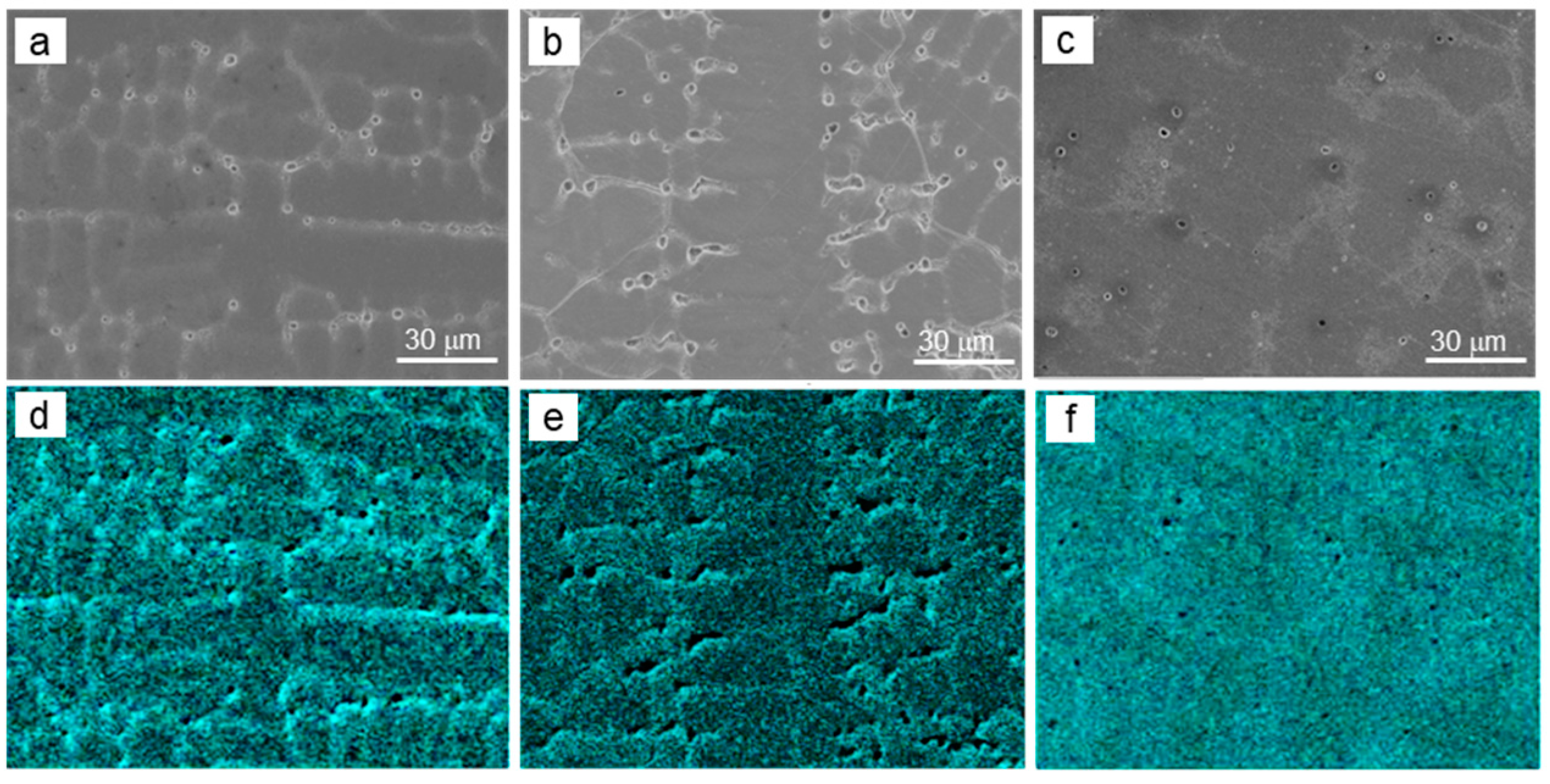
Optical imaging revealed a dendritic microstructure in the weld deposition characteristic for cast metals (Figure 4). The secondary dendrite arm spacing in the as-welded condition was measured to be 13 μm and did not vary with ageing at 610 °C (Table 1). However, after annealing at 1100 °C followed by ageing at 610 °C, it grew to 16 μm. This is in line with previously observed grain growth behaviour in Ni-base alloys [43,44,45]. EDS mapping showed Cu segregation in the as-welded condition associated with a variation in melting points between Cu and Ni (Figure 5a,d). This phenomenon was reported recently for Monel FM60 with a slightly lower Cu content (20.8 compared to 25.5 wt.% in this work) [46]. The Cu segregation remained after ageing at 610 °C but almost completely disappeared after annealing at 1100 °C followed by ageing (compare Figure 5b,e and Figure 5c,f). This can be explained by more intense atom diffusion at elevated temperatures.
Coarse precipitates were identified by SEM-EDS to be mainly TiCN, with some amount of Mn, Al, O, and S occasionally present (Figure 6). Their sizes were in the range of 0.36–0.84 μm (average: 0.7 μm), 0.48–0.96 μm (average: 0.7 μm), and 1.2–4.2 μm (average: 2.1 μm) in the as-welded, aged, and annealed and aged conditions, respectively (Table 1). The particle number density was slightly lower after ageing compared to the as-welded condition; however, it significantly (by 4 times) decreased following annealing and ageing. This can be related to the dissolution of smaller particles accompanied by possible coarsening of larger TiCN. Such behaviour of Ti-rich particles during holding at high temperatures was reported previously for Ti alloys [47], steels [48,49,50], and Ni alloys [51]. In the annealed and aged condition, zones of increased TiCN number density were observed (Figure 4f). This could be related to Ti segregation into the interdendritic areas during solidification [52] followed by particle growth during annealing. Inhomogeneity of TiCN distribution after annealing correlates with a larger variation in hardness values in the annealed and aged condition.
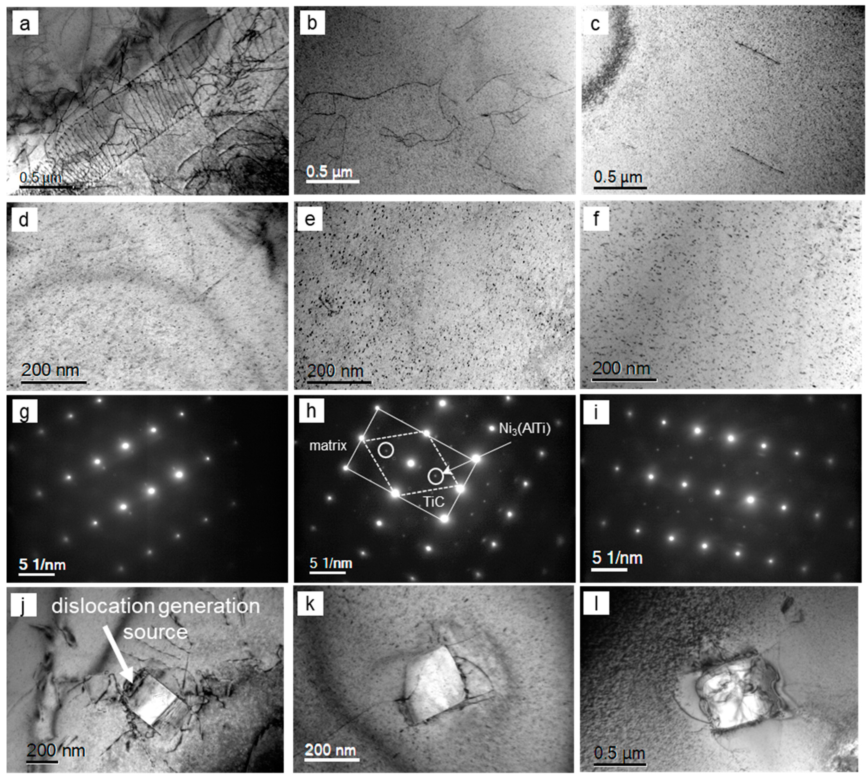
TEM images of the dislocation structure and nano-sized particles are presented in Figure 7, and the measured parameters are summarised in Table 1. The dislocation density in the weld deposition (0.2–0.3 × 10¹⁴ m−2) was in the range of values observed in cast Ni alloys (<1 × 10¹⁴ m−2 [53,54]) and several times lower than this in hot-deformed Ni alloys (1–2 × 10¹⁴ m−2 [55], up to 10 × 1014 m−2 [56], 12 × 1014 m−2 [57]). The dislocation density decreased with heat treatment following annihilation, and this decrease was to a larger extent for the annealed and aged condition compared to the aged.
Fine precipitates were observed by TEM to be in the range of 3–8 nm (average: 4 nm) in the as-welded and aged conditions, and 3–11 nm (average: 4 nm) in the annealed and aged condition. The diffraction pattern analysis confirmed the presence of Ti-rich MC carbides in all material conditions and γ′-Ni3AlTi particles in the aged alloys. This corresponds to well-known behaviour of γ′ precipitates in Ni-base alloys [26,58,59,60,61,62]. The fine particle number density increased with heat treatment due to precipitation, and this occurred to a slightly larger extent during ageing without annealing. Probably, after the particle dissolution during annealing, their reprecipitation during ageing did not fully compensate for the decrease in number density. A higher dislocation density during ageing without annealing facilitated the formation of higher particle number density via the nucleation of precipitates on dislocations [63,64].
An interesting observation is illustrated in Figure 7j–l: coarse particles (or rather interphases between the particles and the matrix) can act as dislocation generation sources, thus increasing the dislocation generation rate. In fact, a higher number density of coarse particles corresponds to a higher work hardening rate in the annealed and aged weld deposition (compare the data in Table 1 and Figure 3b). The influence of a coarse particle on dislocation structure development in a NiFeNbC alloy was analysed in one of our previous publications [25]: coarse NbC particles stimulated development of dislocation tangles and cell walls, which would enhance the work hardening rate.
Microstructural characterisation for a hot-rolled bar subjected to the same heat treatment was presented previously [65]; the average parameters are summarised in Table 1. The following differences were observed for the hot-rolled and weld-deposited microstructures:
  • The secondary dendrite arm spacing in the weld-deposited alloy was smaller than the average grain size (distance between the high angle boundaries) in the hot-rolled condition; this could be related to a relatively fast cooling rate during the solidification of the small weld pool and multiple cycles of recrystallisation and grain growth taking place during hot rolling.
  • Grain coarsening followed the annealing and ageing in both material conditions.
  • The average size of coarse particles decreased and the particle number density increased in the hot-rolled alloy after annealing and ageing; this was an opposite trend to the weld deposition. This could be explained if the particle reprecipitation process during ageing prevailed over their dissolution during annealing in the deformed microstructure. The reason for this might be a 10 times higher dislocation density in the hot-rolled alloy facilitating nucleation on dislocations.
  • The number density of fine particles similarly increased for both alloy conditions during ageing, although to a greater extent in the deformed alloy (from 5422 to 9794 μm−3 in weld deposition against that from 8920 to 11,000 μm−3 in the deformed one).
  • However, after annealing and ageing, the fine particle number density decreased in the hot-rolled alloy and increased in the weld-deposited one; this could follow a larger matrix depletion in Ti and Al in the hot-rolled alloy due to a faster growth of the coarse particles.
  • The dislocation density decreased in both alloy conditions with heat treatment, however, to a lesser extent in the hot-rolled alloy (3 times in the hot-rolled one compared to 5 times in the weld-deposited one for the annealed and aged condition), leading to almost 10 times variation in the dislocation density in the hot-rolled and weld-deposited alloys; this could be related to a slower dislocation annihilation process in the deformed microstructure due to multiple dislocation tangles that slow down the dislocation motion [66,67].

4. Discussion

Comparing the properties of the weld-deposited and hot-rolled alloys, it is worthwhile to discuss three areas: (1) microstructural inhomogeneity, (2) average properties’ values, and (3) effect of cold deformation.
Hardness measurements showed a larger strength inhomogeneity in the heat-treated WAAM alloy compared to this of the hot-rolled one. In addition, the inhomogeneity increased with age hardening heat treatment for the WAAM alloy and decreased for the hot-rolled one. This coincides with the existence of high-Cu-concentration areas and zones of increased TiCN number density in the WAAM alloy. A significant difference in melting points between Cu (1085 °C) and Ni (1455 °C) results in Ni-rich areas solidifying first. Microalloying elements and precipitates (which can potentially form in liquid) would migrate into the last solidifying Cu-rich areas. Therefore, in a solid state, the interdendritic areas would be more highly alloyed and, potentially, can exhibit a higher strength. In fact, for the Ti and C contents in this work, the TiC precipitation could start at temperatures around 1430 °C (presence of nitrogen would increase this temperature). This means that some Ti-rich particles could precipitate in liquid and then be segregated to the interdendritic areas. After annealing, this resulted in a larger variation in the local particle number density and a larger hardness range measured in the weld deposition. In contrast, the hot-rolled microstructure was more homogeneous and the hardness variation was less. This is a result of atom diffusion and multiple grain structure recrystallisation taking place over the relatively long periods of hot rolling compared to the solidification of the weld pool. The microstructure and mechanical properties’ inhomogeneity in the weld deposition may lead to uneven surface degradation in service; for example, wear could be enhanced in softer areas. This requires further investigation.
In spite of about 3 times smaller secondary dendrite arm spacing in the weld deposition than the average grain size in the hot-rolled alloy (which determine the grain boundary strengthening), the average hardness and strength were higher in the hot-rolled alloy. This corresponds to a slightly higher precipitate number density and up to 10 times higher dislocation density in the hot-rolled alloy. Although not studied in this work, the solid solution strengthening could also be higher in the hot-rolled alloy due to higher contents of Al (3.32 wt.% against 3.0 in the welding wire), Ti (0.7 wt.% against 0.5 in the welding wire), and Si (0.25 wt.% against 0.17 in the welding wire).
A high work hardening rate in the WAAM-produced Monel K500 is believed to result from a relatively low initial dislocation density, giving space for dislocation accumulation over a certain strain range, and the presence of coarse (>200 nm) particles, which act as dislocation generation sources. In fact, the largest average size of coarse particles observed in the annealed and aged weld deposition (Table 1) corresponds to the highest work hardening rate for this material condition (Figure 3b). As a result of an increased work hardening rate, only minor cold deformation (0.03–0.10 strain depending on prior heat treatment) was required to increase the yield stress of this layer to the yield stress of the hot-rolled alloy. This opens new opportunities for further development of the WAAM technologies. For instance, the WAAM-processed components can be subjected to sand blasting or shot peening (Figure 8). This would provide the deformation penetration down to several hundreds of microns from the surface and deformation strains of up to 0.15–0.20 [68,69,70], the values that were shown in this work as reasonable enough to equalise the strength of an additively manufactured alloy to this of the hot-rolled one. Positive effects of shot peening on surface strengthening, wear, and corrosion resistance were discussed in several recent publications [71,72,73,74,75].

5. Conclusions

The comparison of the microstructure and properties of hot-rolled and WAAM-processed Monel K500 has shown the following:
  • In the hot-rolled alloy, the average hardness was 20–40 HV higher and the yield stress was 1.8–2.6 times higher than these in the weld deposition (depending on heat treatment). Higher strength of the hot-rolled alloy was associated with up to 60% higher precipitate number density and up to 10 times higher dislocation density.
  • In both material conditions (rolled and WAAM-processed), the hardness and compression yield stress increased after ageing without prior annealing to a greater extent than this after ageing following annealing. This can be explained by two major microstructural transformations taking place during annealing: grain growth—decreases the grain boundary strengthening; and dislocation annihilation—decreases the dislocation strengthening and the number of particle nucleation sites during ageing, leading to a decreased particle number density and precipitation strengthening effect.
  • The hardness inhomogeneity (a variation between the largest and smallest values) was of a similar level in the WAAM-processed alloy as in the hot-rolled one. However, age hardening heat treatment resulted in the hardness inhomogeneity increase in the WAAM alloy and a decrease in the hot-rolled one. This corresponds to the chemical inhomogeneity of the WAAM alloy, namely the presence of Cu-rich and Cu-poor areas and zones of increased number density of TiCN particles. Chemical inhomogeneity may originate from the elements’ segregation during the weld pool solidification over a relatively short period of time.
  • Coarse > 200 nm particles were shown to act as dislocation generation sources, leading to an increase in the work hardening rate. Due to the high work hardening rate, minor cold deformation (0.03–0.10 strain depending on prior heat treatment) was required to equalise the yield stress values for the WAAM alloy to these of the hot-rolled one.
  • On the bases of the obtained results, a new technology was proposed, which includes wire arc additive manufacturing followed by heat treatment in the 610–1100 °C temperature range and cold deformation to 0.15 strain. This technology is expected to produce Monel K500 alloy components with hardness and strength similar to these in the hot-rolled products.

Author Contributions

Conceptualization, O.M., Z.P., H.L. and S.v.D.; methodology, O.M. and A.K.; validation, O.M. and A.K.; formal analysis, O.M. and A.K.; investigation, O.M. and A.K.; resources, Z.P., H.L. and S.v.D.; data curation, A.K. and O.M.; writing—original draft preparation, A.K. and O.M.; writing—review and editing, Z.P., H.L. and S.v.D.; visualisation, O.M. and A.K.; supervision, Z.P., H.L. and S.v.D.; project administration, Z.P., H.L. and S.v.D.; funding acquisition, Z.P., H.L. and S.v.D. All authors have read and agreed to the published version of the manuscript.

Funding

This paper includes research that was supported by DMTC Limited (Australia). The JEOL JEM-2011 TEM and JEOL JSM-7001F FEG-SEM used in this work for microstructure characterisation were funded by the Australian Research Council grants LE0237478 and LE0882613.

Institutional Review Board Statement

No ethical approval was required for this research as it did not involve human tissue or any other parts of living organisms.

Data Availability Statement

The raw data supporting the conclusions of this article will be made available by the authors on request.

Acknowledgments

The authors have prepared this paper in accordance with the intellectual property rights granted by a DMTC Project Agreement. The experiments were carried out at the University of Wollongong.

Conflicts of Interest

The authors declare no conflicts of interest. The authors declare that this study received funding from DMTC Limited (Australia). The funder was not involved in the study design, collection, analysis, interpretation of data, the writing of this article or the decision to submit it for publication.

References

  1. Wang, F.; Williams, S.; Rush, M. Morphology investigation on direct current pulsed gas tungsten arc welded additive layer manufactured Ti6Al4V alloy. Int. J. Adv. Manuf. Technol. 2011, 57, 597–603. [Google Scholar] [CrossRef]
  2. Wu, B.; Ding, D.; Pan, Z.; Cuiuri, D.; Li, H.; Han, J.; Fei, Z. Effects of heat accumulation on the arc characteristics and metal transfer behavior in Wire Arc Additive Manufacturing of Ti6Al4V. J. Mater. Process. Technol. 2017, 250, 304–312. [Google Scholar] [CrossRef]
  3. Davis, A.E.; Breheny, C.I.; Fellowes, J.; Nwankpa, U.; Martina, F.; Ding, J.; Machry, T.; Prangnell, P.B. Mechanical performance and microstructural characterisation of titanium alloy-alloy composites built by wire-arc additive manufacture. Mater. Sci. Eng. A 2019, 765, 138289. [Google Scholar] [CrossRef]
  4. Lin, Z.; Song, K.; Yu, X. A review on wire and arc additive manufacturing of titanium alloy. J. Manuf. Processes 2021, 70, 24–45. [Google Scholar] [CrossRef]
  5. Haden, C.V.; Zeng, G.; Carter, F.M., III; Ruhl, C.; Krick, B.A.; Harlow, D.G. Wire and arc additive manufactured steel: Tensile and wear properties. Addit. Manuf. 2017, 16, 115–123. [Google Scholar] [CrossRef]
  6. Shen, C.; Pan, Z.; Cuiuri, D.; Ding, D.; Li, H. Influences of deposition current and interpass temperature to the Fe3Al-based iron aluminide fabricated using wire-arc additive manufacturing process. Int. J. Adv. Manuf. Technol. 2017, 88, 2009–2018. [Google Scholar] [CrossRef]
  7. Wang, L.; Xue, J.; Wang, Q. Correlation between arc mode, microstructure, and mechanical properties during wire arc additive manufacturing of 316L stainless steel. Mater. Sci. Eng. A 2019, 751, 183–190. [Google Scholar] [CrossRef]
  8. Rodrigues, T.A.; Duarte, V.R.; Tomás, D.; Avila, J.A.; Escobar, J.D.; Rossinyol, E.; Schell, N.; Santos, T.G.; Oliveira, J.P. In-situ strengthening of a high strength low alloy steel during Wire and Arc Additive Manufacturing (WAAM). Addit. Manuf. 2020, 34, 101200. [Google Scholar] [CrossRef]
  9. Cong, B.; Ding, J.; Williams, S. Effect of arc mode in cold metal transfer process on porosity of additively manufactured Al-6.3%Cu alloy. Int. J. Adv. Manuf. Technol. 2015, 76, 1593–1606. [Google Scholar] [CrossRef]
  10. Gu, J.; Wang, X.; Bai, J.; Ding, J.; Williams, S.; Zhai, Y.; Liu, K. Deformation microstructures and strengthening mechanisms for the wire + arc additively manufactured Al-Mg4.5Mn alloy with inter-layer rolling. Mater. Sci. Eng. A 2018, 712, 292–301. [Google Scholar] [CrossRef]
  11. Qi, Z.; Cong, B.; Qi, B.; Sun, H.; Zhao, G.; Ding, J. Microstructure and mechanical properties of double-wire+arc additively manufactured Al-Cu-Mg alloys. J. Mater. Process. Technol. 2018, 255, 347–353. [Google Scholar] [CrossRef]
  12. Klein, T.; Reiter, L.; Schnall, M. Wire-arc additive manufacturing of Al-Zn5.5-Mg-Cu (ML7075): Shifting paradigms of additive manufacture-ability. Mater. Lett. 2022, 313, 131841. [Google Scholar] [CrossRef]
  13. Ding, D.; Pan, Z.; van Duin, S.; Li, H.; Shen, C. Fabricating Superior NiAl Bronze Components through Wire Arc Additive Manufacturing. Materials 2016, 9, 652. [Google Scholar] [CrossRef] [PubMed]
  14. Zhang, H.; Hu, S.; Wang, Z.; Liang, Y. The effect of welding speed on microstructures of cold metal transfer deposited AZ31 magnesium alloy clad. Mater. Des. 2015, 86, 894–901. [Google Scholar] [CrossRef]
  15. Li, J.; Qiu, Y.; Yang, J.; Sheng, Y.; Yi, Y.; Zeng, X.; Chen, L.; Yin, F.; Su, J.; Zhang, T.; et al. Effect of grain refinement induced by wire and arc additive manufacture (WAAM) on the corrosion behaviors of AZ31 magnesium alloy in NaCl solution. J. Magnes. Alloys 2023, 11, 217–229. [Google Scholar] [CrossRef]
  16. Baufeld, B. Mechanical Properties of Inconel 718 Parts Manufactured by Shaped Metal Deposition (SMD). J. Mater. Eng. Perform. 2012, 21, 1416–1421. [Google Scholar] [CrossRef]
  17. Xu, F.J.; Lv, Y.H.; Xu, B.S.; Liu, Y.X.; Shu, F.Y.; He, P. Effect of deposition strategy on the microstructure and mechanical properties of Inconel 625 superalloy fabricated by pulsed plasma arc deposition. Mater. Des. 2013, 45, 446–455. [Google Scholar] [CrossRef]
  18. James, W.S.; Ganguly, S.; Pardal, G. High temperature performance of wire-arc additive manufactured Inconel 718. Sci. Rep. 2023, 13, 4541. [Google Scholar] [CrossRef]
  19. Wang, J.; Pan, Z.; Carpenter, K.; Han, J.; Wang, Z.; Li, H. Comparative study on crystallographic orientation, precipitation, phase transformation and mechanical response of Ni-rich NiTi alloy fabricated by WAAM at elevated substrate heating temperatures. Mater. Sci. Eng. A 2021, 800, 140307. [Google Scholar] [CrossRef]
  20. Ke, W.C.; Oliveira, J.P.; Cong, B.Q.; Ao, S.S.; Qi, Z.W.; Peng, B.; Zeng, Z. Multi-layer deposition mechanism in ultra high-frequency pulsed wire arc additive manufacturing (WAAM) of NiTi shape memory alloys. Addit. Manuf. 2022, 50, 102513. [Google Scholar] [CrossRef]
  21. Marenych, O.O.; Ding, D.; Pan, Z.; Kostryzhev, A.G.; Li, H.; van Duin, S. Effect of chemical composition on microstructure, strength and wear resistance of wire deposited Ni-Cu alloys. Addit. Manuf. 2018, 24, 30–36. [Google Scholar] [CrossRef]
  22. Marenych, O.; Kostryzhev, A.; Shen, C.; Pan, Z.; Li, H.; van Duin, S. Precipitation strengthening in Ni–Cu alloys fabricated using wire arc additive manufacturing technology. Metals 2019, 9, 105. [Google Scholar] [CrossRef]
  23. Qi, F.; Fu, H.; Song, Y.; Yun, X. Regulation of dislocation density and precipitates to maximize the mechanical strength and electrical conductivity in continuously extruded Cu–Ni–Si alloys. J. Mater. Res. Technol. 2024, 30, 8519–8528. [Google Scholar] [CrossRef]
  24. Poddar, D.; Cizek, P.; Beladi, H.; Hodgson, P.D. Evolution of strain-induced precipitates in a model austenitic Fe–30Ni–Nb steel and their effect on the flow behaviour. Acta Mater. 2014, 80, 1–15. [Google Scholar] [CrossRef]
  25. Kostryzhev, A.G.; Mannan, P.; Marenych, O.O. High temperature dislocation structure and NbC precipitation in three Ni-Fe-Nb-C model alloys. J. Mater. Sci. 2015, 50, 7115–7125. [Google Scholar] [CrossRef]
  26. Marenych, O.; Kostryzhev, A. Strengthening mechanisms in Ni-Cu alloys: A review. Metals 2020, 10, 1358. [Google Scholar] [CrossRef]
  27. Mishra, D.; Vignesh, M.K.; Raj, B.G.; Srungavarapu, P.; Ramkumar, K.D.; Arivazhagan, N.; Narayanan, S. Mechanical characterization of Monel 400 and 316 stainless steel weldments. Procedia Eng. 2014, 75, 24–28. [Google Scholar] [CrossRef]
  28. Khandke, S.P.; Surve, A.; Patil, D.; Balan, A.S.S.; Kuppan, P.; Oyyaravelu, R. Grindability studies on monel under different cooling environments. Mater. Today Proc. 2018, 5, 12559–12569. [Google Scholar] [CrossRef]
  29. Devendranath, R.K.; Arivazhagan, N.; Narayanan, S.; Narayanan, M.; Mondody, A.; Kashyap, R. Development of defect free Monel 400 welds for marine application. Adv. Mater. Res. 2012, 383–390, 4693–4696. [Google Scholar] [CrossRef]
  30. Shoemaker, L.E.; Smith, G.D. A century of Monel metal: 1906–2006. JOM 2006, 58, 22–26. [Google Scholar] [CrossRef]
  31. Dutta, R.S. Corrosion aspects of Ni–Cr–Fe based and Ni–Cu based steam generator tube materials. J. Nucl. Mater. 2009, 393, 343–349. [Google Scholar] [CrossRef]
  32. Francis, J.T.; Brennenstu, A.M.; Ramamurthy, S.N.; Mcintyre, S. Use of ToF-SIMS in the study of corrosion processes: Monel 400 steam generator tubing under CANDU start-up conditions. Surf. Interface Anal. 2002, 34, 189–191. [Google Scholar] [CrossRef]
  33. Hodge, F.G. The history of solid-solution-strengthened Ni alloys for aqueous corrosion service. JOM 2006, 58, 28–30. [Google Scholar] [CrossRef]
  34. Gaines, R.H. Monel metal. J. Ind. Eng. Chem. 1912, 4, 354–358. [Google Scholar] [CrossRef]
  35. Ganley, J.C. High temperature and pressure alkaline electrolysis. Int. J. Hydrogen Energy 2009, 34, 3604–3611. [Google Scholar] [CrossRef]
  36. Werner, T.C.; Yan, Y.; Mullen, D.; Halimic, E. Experimental analysis of a high temperature water heat pipe for thermal storage applications. Therm. Sci. Eng. Prog. 2020, 19, 100564. [Google Scholar] [CrossRef]
  37. Ghorbani, M.M.; Taherian, R.; Bozorg, M. Investigation on physical and electrochemical properties of TiN-coated Monel alloy used for bipolar plates of proton exchange membrane fuel cell. Mater. Chem. Phys. 2019, 238, 121916. [Google Scholar] [CrossRef]
  38. Solmaz, R.; Döner, A.; Kardas, G. The stability of hydrogen evolution activity and corrosion behavior of NiCu coatings with long-term electrolysis in alkaline solution. Int. J. Hydrogen Energy 2009, 34, 2089–2094. [Google Scholar] [CrossRef]
  39. Ahn, S.H.; Park, H.-Y.; Choi, I.; Yoo, S.J.; Hwang, S.J.; Kim, H.-J.; Cho, E.A.; Yoon, C.W.; Park, H.; Son, H.; et al. Electrochemically fabricated NiCu alloy catalysts for hydrogen production in alkaline water electrolysis. Int. J. Hydrogen Energy 2013, 38, 13493–13501. [Google Scholar] [CrossRef]
  40. Wang, K.; Xia, M.; Xiao, T.; Lei, T.; Yan, W. Metallurgically prepared NiCu alloys as cathode materials for hydrogen evolution reaction. Mater. Chem. Phys. 2017, 186, 61–66. [Google Scholar] [CrossRef]
  41. Ghosh, S.K.; Grover, A.K.; Dey, G.K.; Suri, A.K. Synthesis of corrosion-resistant nanocrystalline nickel–copper alloy coatings by pulse-plating technique. Def. Sci. J. 2005, 55, 63–74. [Google Scholar] [CrossRef]
  42. Geramipour, F.; Mousavi Khoei, S.M.; Shooshtari Gugtapeh, H. Effect of shaped waveform on structure and electrochemical corrosion behavior of pulse electrodeposited Ni–Cu alloy coatings. Surf. Coat. Technol. 2021, 424, 127643. [Google Scholar] [CrossRef]
  43. Rao, A.S.; Manda, P.; Mohan, M.K.; Nandy, T.K.; Singh, A.K. Microstructure, texture and mechanical properties of hot rolled and annealed Ni-Fe-W and Ni-Fe-W-Co matrix alloys. J. Alloys Compd. 2018, 742, 937–951. [Google Scholar]
  44. Song, Y.; Fan, J.; Liu, X.; Zhang, P.; Li, J. Thermal processing map and microstructure evolution of Inconel 625 alloy sheet based on plane strain compression deformation. Materials 2021, 14, 5059. [Google Scholar] [CrossRef]
  45. Yang, F.; Dong, L.; Hu, X.; Zhou, X.; Xie, Z.; Fang, F. Effect of solution treatment temperature upon the microstructure and mechanical properties of hot rolled Inconel 625 alloy. J. Mater. Sci. 2020, 55, 5613–5626. [Google Scholar] [CrossRef]
  46. Kannan, A.R.; Kumar, S.M.; Pramod, R.; Shanmugam, N.S.; Vishnukumar, M.; Channabasavanna, S.G. Microstructure and corrosion resistance of Ni-Cu alloy fabricated through wire arc additive manufacturing. Mater. Lett. 2022, 308, 131262. [Google Scholar] [CrossRef]
  47. Hu, D.; Loretto, M.H. Coarsening of TiC particles in a rapidly solidified Ti6A14V-TiC composite. J. Alloys Compd. 1994, 209, 167–173. [Google Scholar] [CrossRef]
  48. Gustafson, A. Coarsening of TiC in austenitic stainless steel–experiments and simulations in comparison. Mater. Sci. Eng. A 2000, 287, 52–58. [Google Scholar] [CrossRef]
  49. Jang, J.H.; Lee, C.-H.; Han, H.N.; Bhadeshia, H.K.D.H.; Suh, D.-W. Modelling coarsening behaviour of TiC precipitates in high strength, low alloy steels. Mater. Sci. Technol. 2013, 29, 1074–1079. [Google Scholar] [CrossRef]
  50. Solis-Bravo, G.; Merwin, M.; Garcia, C.I. Impact of precipitate morphology on the dissolution and grain-coarsening behavior of a Ti-Nb microalloyed linepipe steel. Metals 2020, 10, 89. [Google Scholar] [CrossRef]
  51. Marchese, G.; Aversa, A.; Bassini, E. Microstructure and hardness evolution of solution annealed Inconel 625/TiC composite processed by laser powder bed fusion. Metals 2021, 11, 929. [Google Scholar] [CrossRef]
  52. Shi, P.; Xu, W.; Fu, B.; Liu, J.; Zhang, J.; Wang, K.; Liu, X. Pore defects in a nickel-based superalloy with high Ti content. Prog. Nat. Sci. 2022, 32, 456–462. [Google Scholar] [CrossRef]
  53. Agudo-Jacome, L.; Nörtershäuser, P.; Heyer, J.-K.; Lahni, A.; Frenzel, J.; Dlouhy, A.; Somsen, C.; Eggeler, G. High-temperature and low-stress creep anisotropy of single-crystal superalloys. Acta Mater. 2013, 61, 2926–2943. [Google Scholar] [CrossRef]
  54. Nörtershäuser, P.; Frenzel, J.; Ludwig, A.; Neuking, K.; Eggeler, G. The effect of cast microstructure and crystallography on rafting, dislocation plasticity and creep anisotropy of single crystal Ni-base superalloys. Mater. Sci. Eng. A 2015, 626, 305–312. [Google Scholar] [CrossRef]
  55. Yamaguchi, I.; Yonemura, M. Recovery and recrystallization behaviors of Ni–30 Mass pct fe alloy during uniaxial cold and hot compression. Metall. Mater. Trans. A 2021, 52, 3517–3529. [Google Scholar] [CrossRef]
  56. Joseph, A.S.; Gupta, P.; Kumar, N.; Poletti, M.C.; Yadav, S.D. An advanced dislocation density-based approach to model the tensile flow behaviour of a 64.7Ni–31.96Cu alloy. Philos. Mag. 2022, 102, 1481–1504. [Google Scholar] [CrossRef]
  57. Zhou, G.; Pantleon, W.; Xu, R.; Liu, W.; Chen, K.; Zhang, Y. Quantification of local dislocation density using 3D synchrotron monochromatic X-ray microdiffraction. Mater. Res. Lett. 2021, 9, 182–188. [Google Scholar] [CrossRef]
  58. Moskovic, R. Precipitation of Ni3Al in a nickel rich NiAl. J. Mater. Sci. 1977, 12, 1895–1902. [Google Scholar] [CrossRef]
  59. Macchi, C.E.; Somoza, A.; Santos, G.; Petkov, M.; Lynn, K.G. On the precipitation sequence in a Ni-based superalloy: A Coincidence Doppler Broadening study. Phys. Status Solidi C 2007, 4, 3542–3545. [Google Scholar] [CrossRef]
  60. Ardell, A.J. Trans-interface-diffusion-controlled coarsening of c0 precipitates in ternary Ni–Al–Cr alloys. Acta Mater. 2013, 61, 7828–7840. [Google Scholar] [CrossRef]
  61. Chen, Y.Q.; Francis, E.; Robson, J.; Preuss, M.; Haigh, S.J. Compositional variations for small-scale gamma prime (γ′) precipitates formed at different cooling rates in an advanced Ni-based superalloy. Acta Mater. 2015, 85, 199–206. [Google Scholar] [CrossRef]
  62. Tang, S.; Ning, L.K.; Xin, T.Z.; Zheng, Z. Coarsening behavior of gamma prime precipitates in a nickel based single crystal superalloy. J. Mater. Sci. Technol. 2016, 32, 172–176. [Google Scholar] [CrossRef]
  63. Monajati, H.; Zarandi, F.; Jahazi, M.; Yue, S. Strain induced g′ precipitation in nickel base superalloy Udimet 720 using a stress relaxation based technique. Scr. Mater. 2005, 52, 771–776. [Google Scholar] [CrossRef]
  64. Liu, T.; Cheng, X.; Luo, R.; Cao, Y.; Ding, H.; Chen, L.; Wang, Q.; Zhang, B. Evolution of strain-induced precipitates in Inconel 617B alloy and their effect on flow behavior. J. Alloys Compd. 2021, 891, 161992. [Google Scholar] [CrossRef]
  65. Kostryzhev, A.G.; Marenych, O.O.; Pan, Z.; Li, H.; van Duin, S. Strengthening mechanisms in Monel K500 alloyed with Al and Ti. J. Mater. Sci. 2023, 58, 4150–4164. [Google Scholar] [CrossRef]
  66. Kohnert, A.A.; Capolungo, L. The kinetics of static recovery by dislocation climb. Comput. Mater. 2022, 8, 104. [Google Scholar] [CrossRef]
  67. Saha, D.C.; Biro, E.; Gerlich, A.P.; Zhou, Y. Martensite tempering kinetics: Effects of dislocation density and heating rates. Mater. Charact. 2020, 168, 110564. [Google Scholar] [CrossRef]
  68. Frija, M.; Hassine, T.; Fathallah, R.; Bouraoui, C.; Dogui, A. Finite element modelling of shot peening process: Prediction of the compressive residual stresses, the plastic deformations and the surface integrity. Mater. Sci. Eng. A 2006, 426, 173–180. [Google Scholar] [CrossRef]
  69. Soady, K.A.; Mellor, B.G.; West, G.D.; Harrison, G.; Morris, A.; Reed, P.A.S. Evaluating surface deformation and near surface strain hardening resulting from shot peening a tempered martensitic steel and application to low cycle fatigue. Int. J. Fatigue 2013, 54, 106–117. [Google Scholar] [CrossRef]
  70. Purohit, R.; Verma, C.S.; Rana, R.S.; Dwivedi, R.; Dwivedi, S. Simulation of shot peening process. Mater. Today Proc. 2017, 4, 1244–1251. [Google Scholar] [CrossRef]
  71. Bagheri, S.; Guagliano, M. Review of shot peening processes to obtain nanocrystalline surfaces in metal alloys. Surf. Eng. 2009, 25, 3–14. [Google Scholar] [CrossRef]
  72. Zhiming, L.; Laimin, S.; Shenjin, Z.; Zhidong, T.; Yazhou, J. Effect of high energy shot peening pressure on the stress corrosion cracking of the weld joint of 304 austenitic stainless steel. Mater. Sci. Eng. A 2015, 637, 170–174. [Google Scholar] [CrossRef]
  73. Dai, S.; Zhu, Y.; Huang, Z. Microstructure evolution and strengthening mechanisms of pure titanium with nano-structured surface obtained by high energy shot peening. Vacuum 2016, 125, 215–221. [Google Scholar] [CrossRef]
  74. Kovaci, H.; Bozkurt, Y.B.; Yetim, A.F.; Aslan, M.; Çelik, A. The effect of surface plastic deformation produced by shot peening on corrosion behavior of a low-alloy steel. Surf. Coat. Technol. 2019, 360, 78–86. [Google Scholar] [CrossRef]
  75. Zhang, C.; Zheng, M.; Wang, Y.; Gao, P.; Gan, B. Effect of high energy shot peening on the wear resistance of TiN films on a TA2 surface. Surf. Coat. Technol. 2019, 378, 124821. [Google Scholar] [CrossRef]
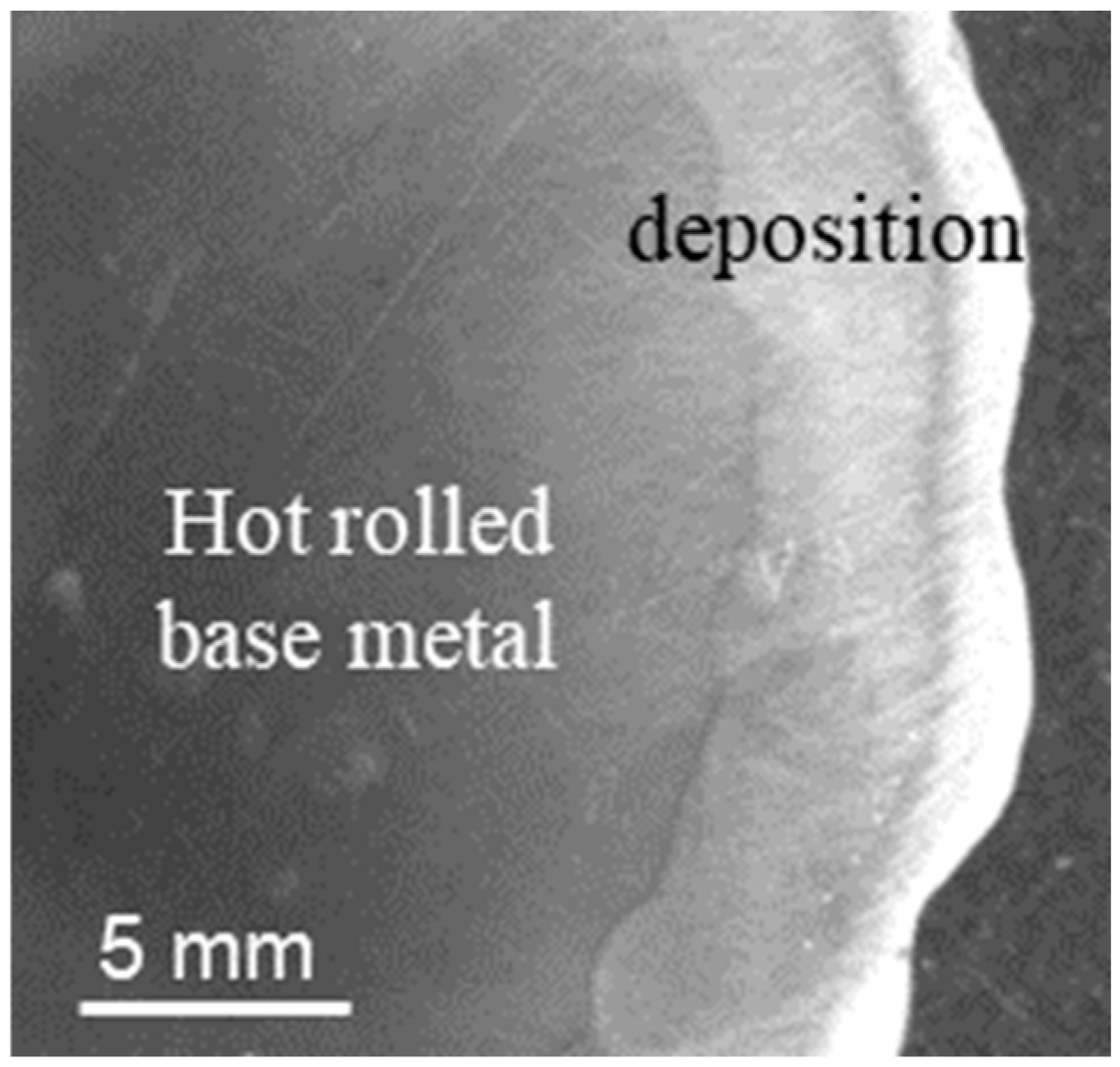
Figure 1. An optical image of the rod cross-section after the deposition.
Metals 14 00813 g001
Figure 4. (ac) Optical and (df) SEM images of the grain structure for the weld deposition in (a,d) as-welded, (b,e) aged, and (c,f) annealed and aged conditions.
Metals 14 00813 g004
Figure 5. (ac) SEM images and (df) Cu EDS maps for the weld deposition in (a,d) as-welded, (b,e) aged, and (c,f) annealed and aged conditions.
Metals 14 00813 g005
Figure 6. (a) SEM image and (b) the corresponding EDS spectrum of a TiCN particle.
Metals 14 00813 g006
Figure 7. Bright field TEM images of (ac) dislocation structure and (df) nano-particles, (gi) typical diffraction patterns, and (jl) coarse particles acting as dislocation generating sources in (a,d,g,j) as-welded, (b,e,h,k) aged, and (c,f,i,l) annealed and aged conditions.
Metals 14 00813 g007
Figure 8. New technology to produce additively manufactured parts with hardness and strength values similar to those after hot rolling.
Metals 14 00813 g008
Table 1. Microstructure and mechanical properties of the studied alloy.
Material ConditionDendrite
Arm/
Grain Size, μm
Coarse ParticlesFine ParticlesDislocation Density,
×1014 m−2
Hardness
HV
Yield Stress, MPa
Average Size, μmNumber Density, μm−2Area FractionAverage Size, nmNumber Density, μm−3Volume Fraction
Weld depositionAs-welded13 ± 40.7 ± 0.20.0130.00484 ± 154220.000200.2–0.3153 ± 5120 ± 10
Aged13 ± 40.7 ± 0.20.0120.00474 ± 197940.000440.08–0.2263 ± 10220 ± 14
Annealed and aged16 ± 42.1 ± 0.70.0030.01164 ± 294180.000630.04–0.08238 ± 10200 ± 12
Hot-rolled rodAs-received34 ± 161.2 ± 0.50.0110.01533 ± 189200.000251.2–1.3191 ± 8320 ± 10
Aged36 ± 181.1 ± 0.30.0100.01504 ± 211,0000.000620.9–1.0285 ± 5470 ± 15
Annealed and aged77 ± 350.9 ± 0.20.0240.01513 ± 186650.000190.4–0.5276 ± 7360 ± 12
Disclaimer/Publisher’s Note: The statements, opinions and data contained in all publications are solely those of the individual author(s) and contributor(s) and not of MDPI and/or the editor(s). MDPI and/or the editor(s) disclaim responsibility for any injury to people or property resulting from any ideas, methods, instructions or products referred to in the content.