

Assessment of the Thermomechanical Behavior and Microstructure of AA 7075-T6 Aluminum Alloy Lap Joints at Optimal Predicted FSW Process Parameters
 , ,
, ,  and
and
Abstract
:1. Introduction
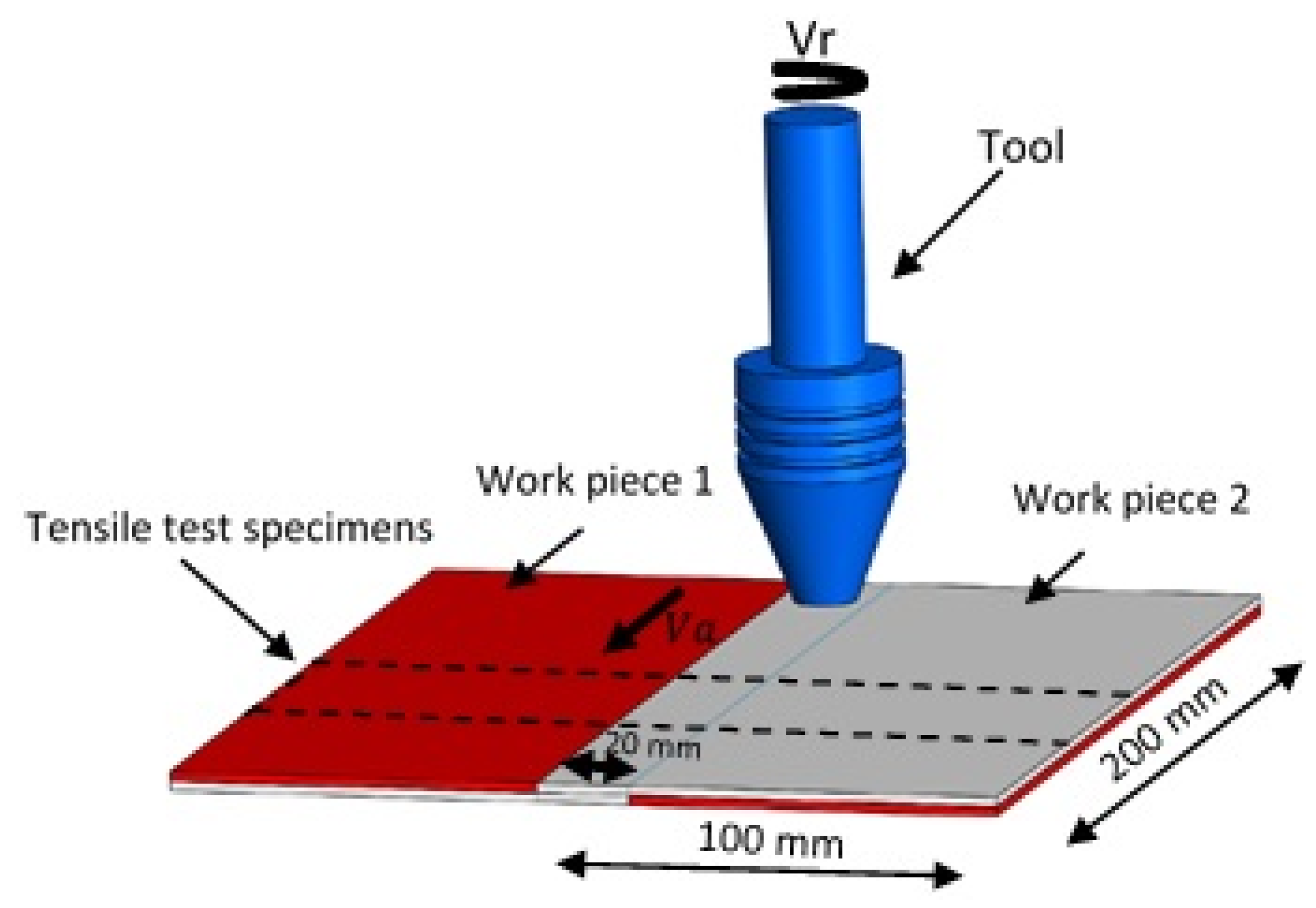
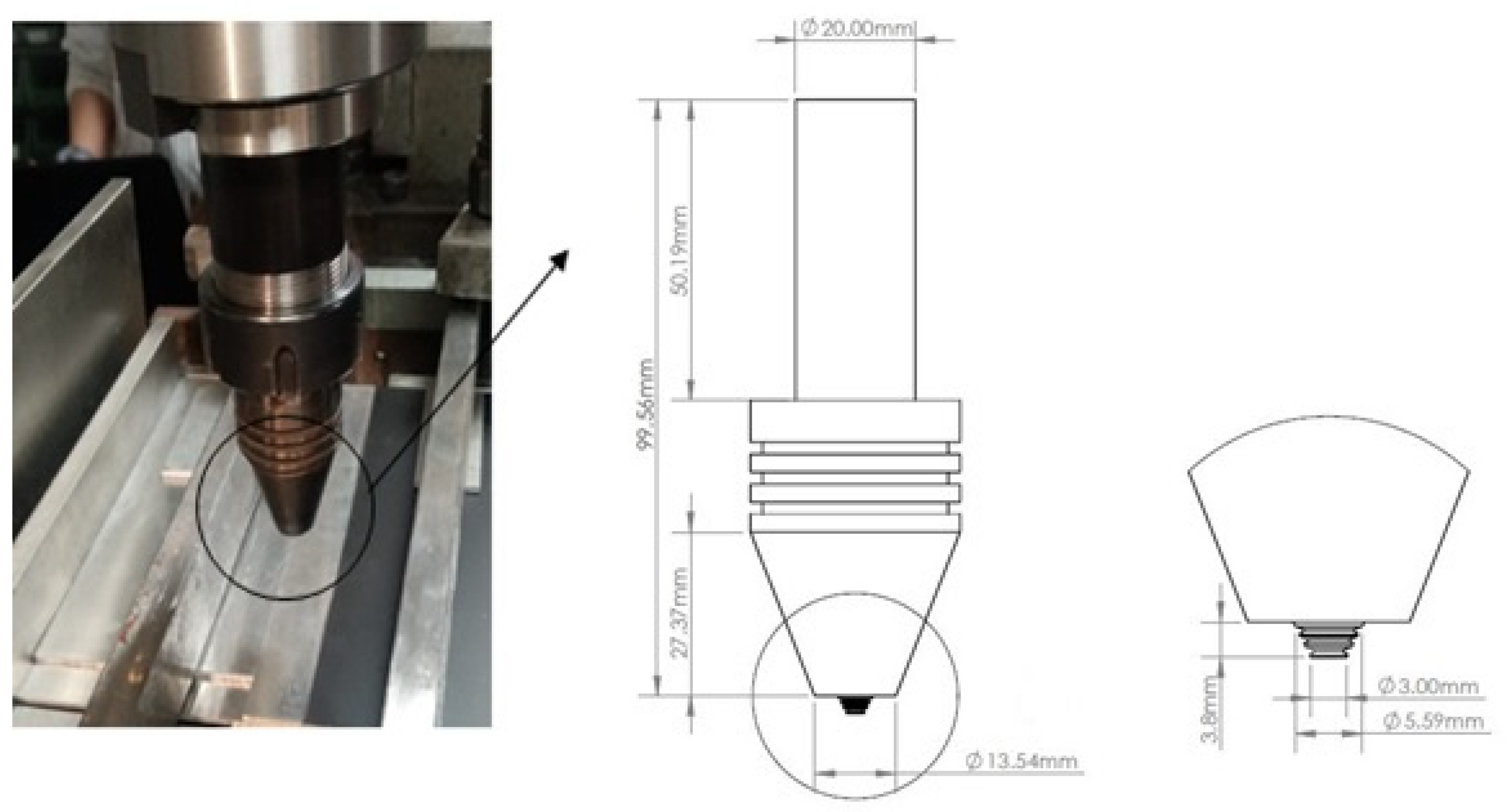
2. Experimental Set-Up
2.1. Prediction of Optimal FSW Process Conditions
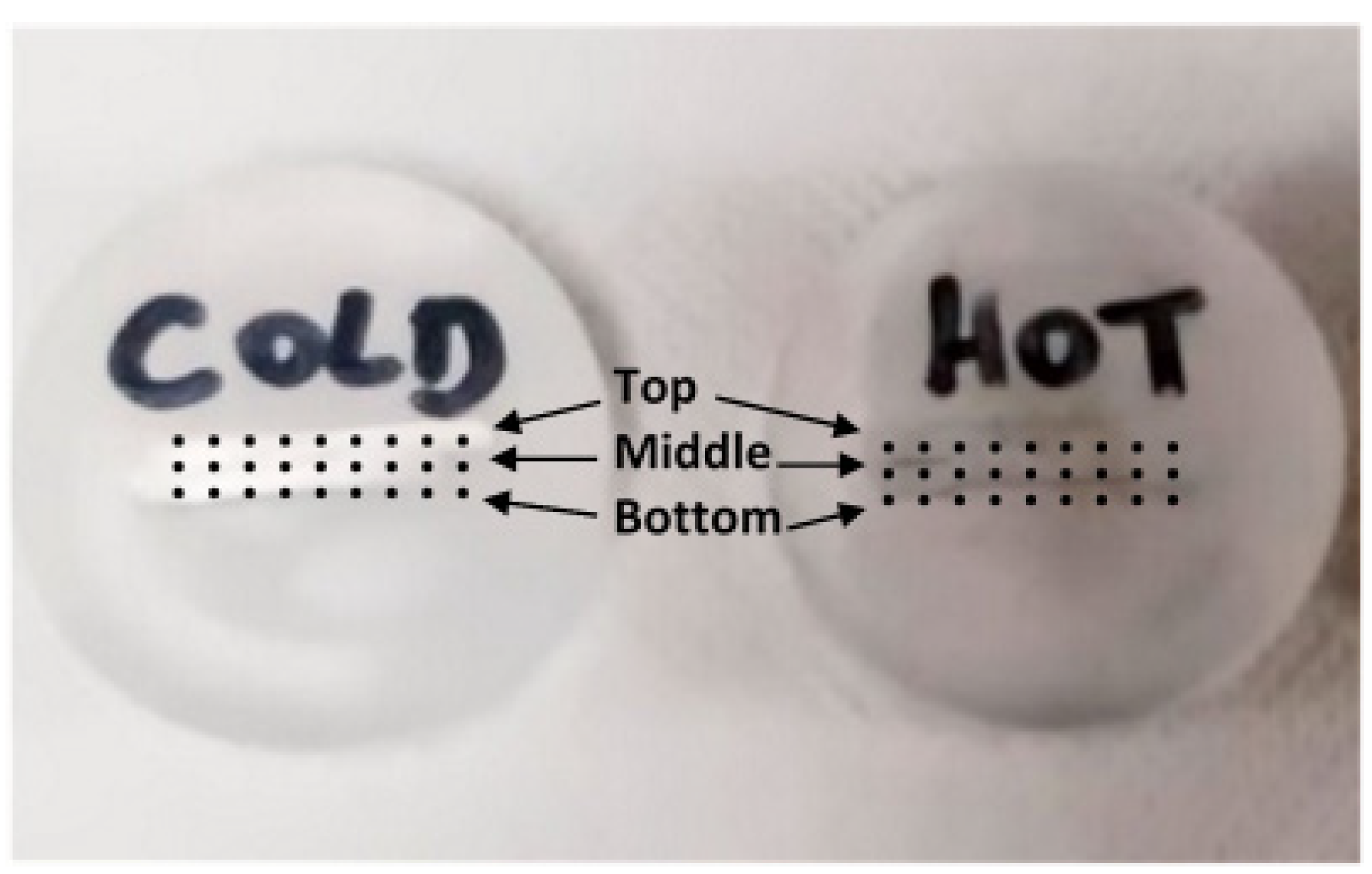
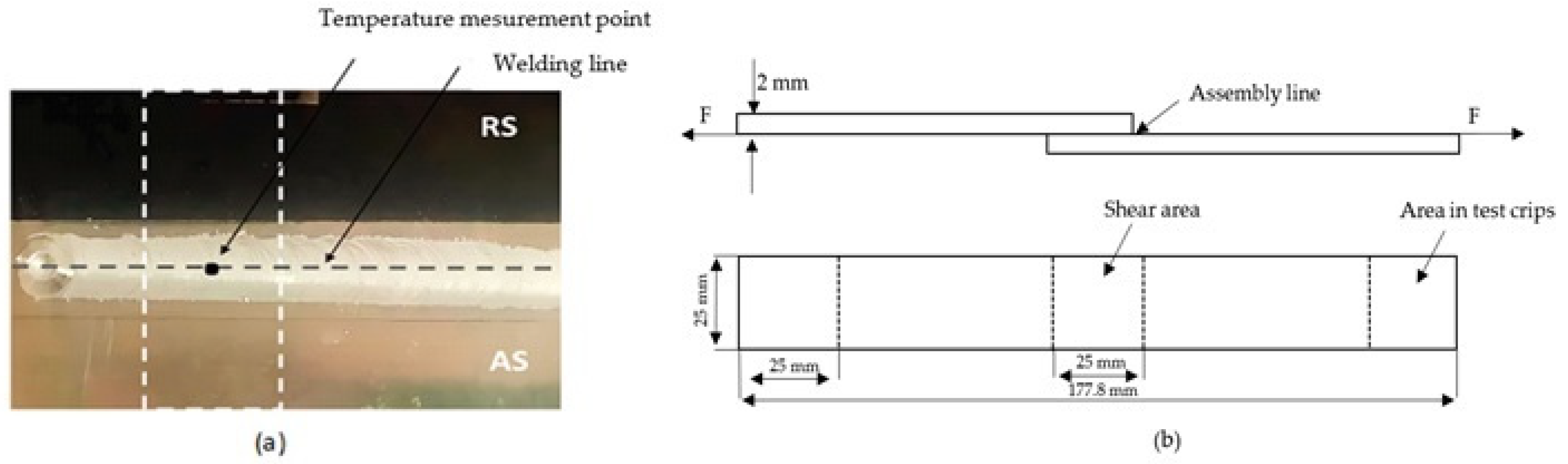
2.2. Temperature Measurement
2.3. Test Specimen Preparation
3. Results and Discussion
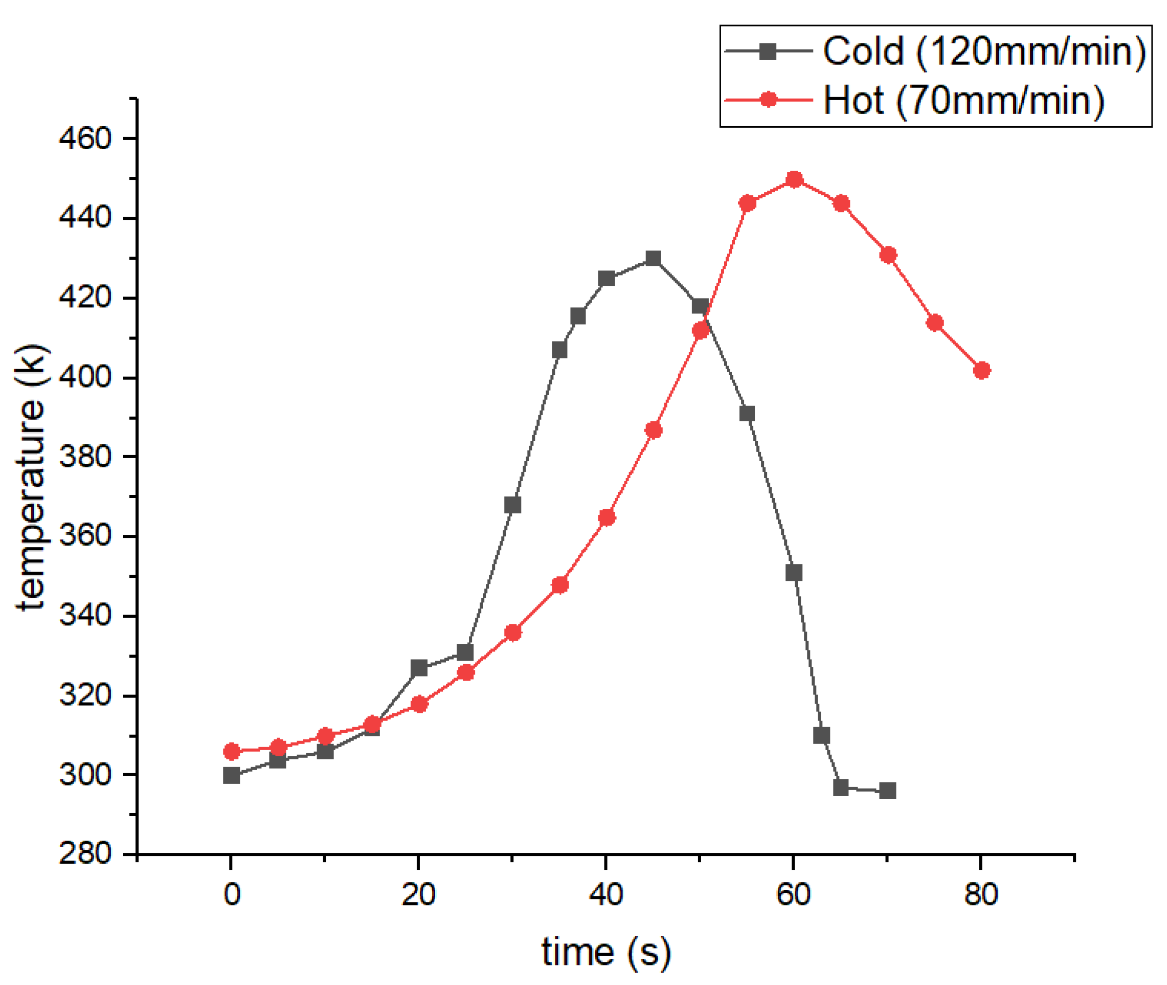
3.1. Temperature
3.2. Microhardness
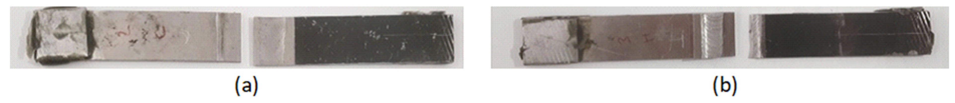
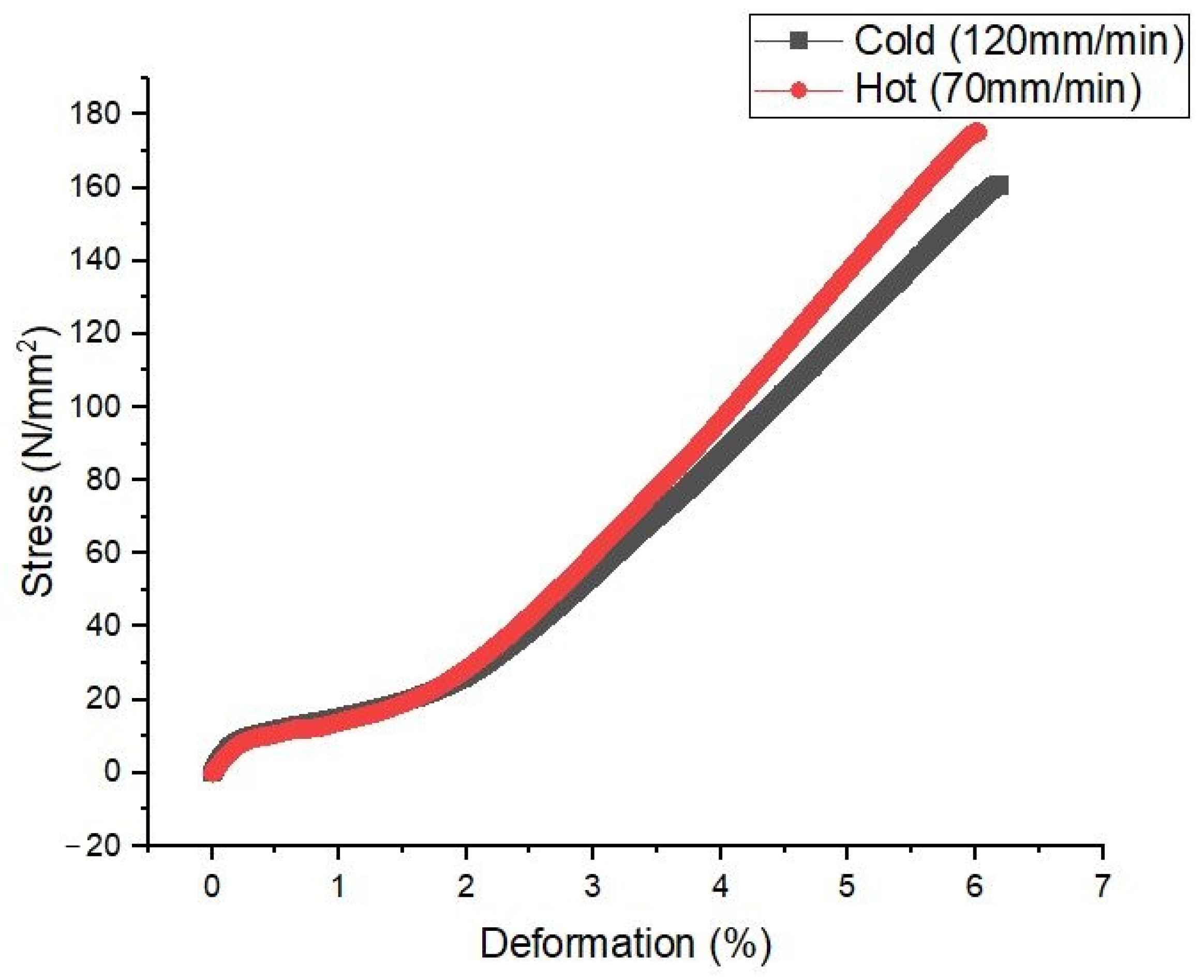
3.3. Tensile Test
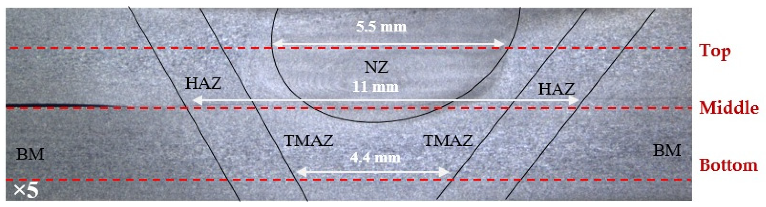
3.4. Microstructure
4. Conclusions
- -
- The lowest ultimate tensile strength of AA7075-T6 was obtained under hot welding conditions. The ultimate tensile strength decreased by decreasing the welding speed. This trend was also observed for microhardness. This is mainly attributed to the decline in the material’s inherent strength and ductility due to the microstructure modification caused by the heat generated by the tool’s welding speed.
- -
- The FSW process parameters were evaluated via tensile test and hardness tests. Comparing the two welding speeds, at a rotational speed of 1320 rpm, the best parameters were obtained at a welding speed of 120 mm/min.
- -
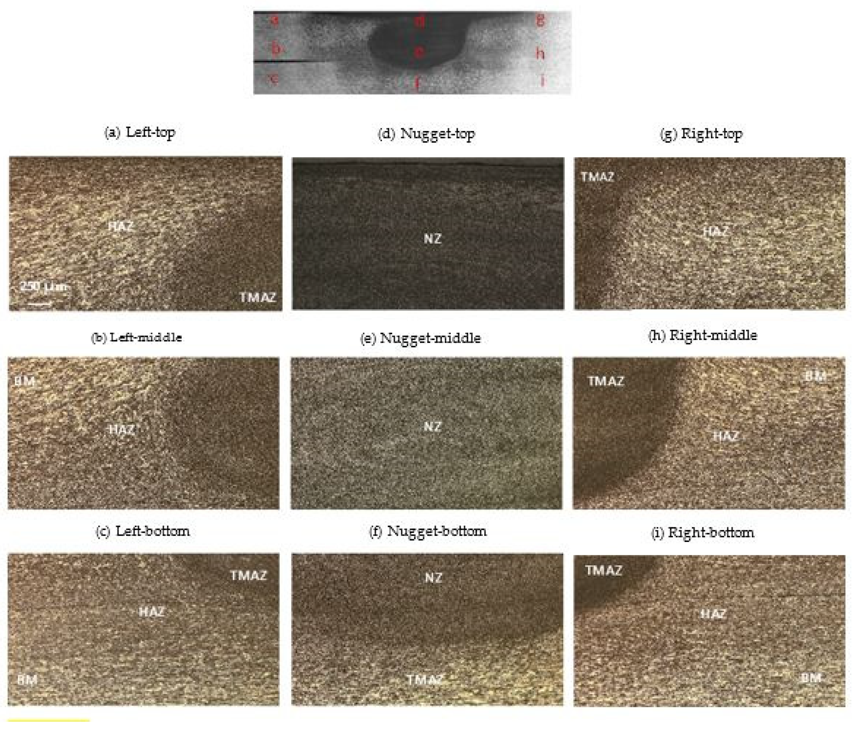
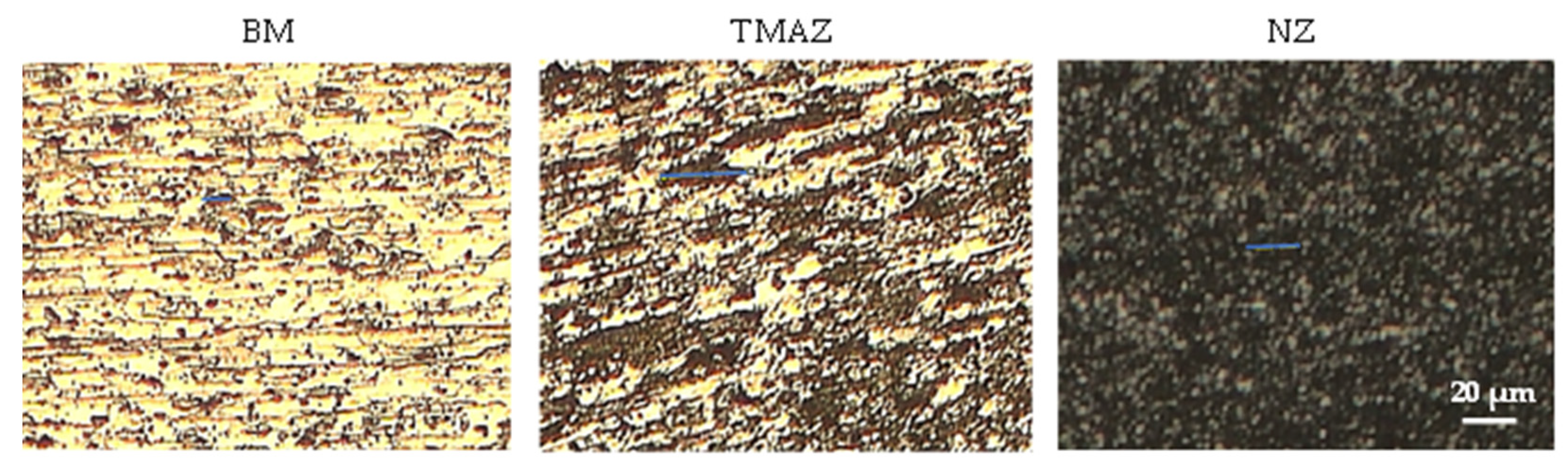
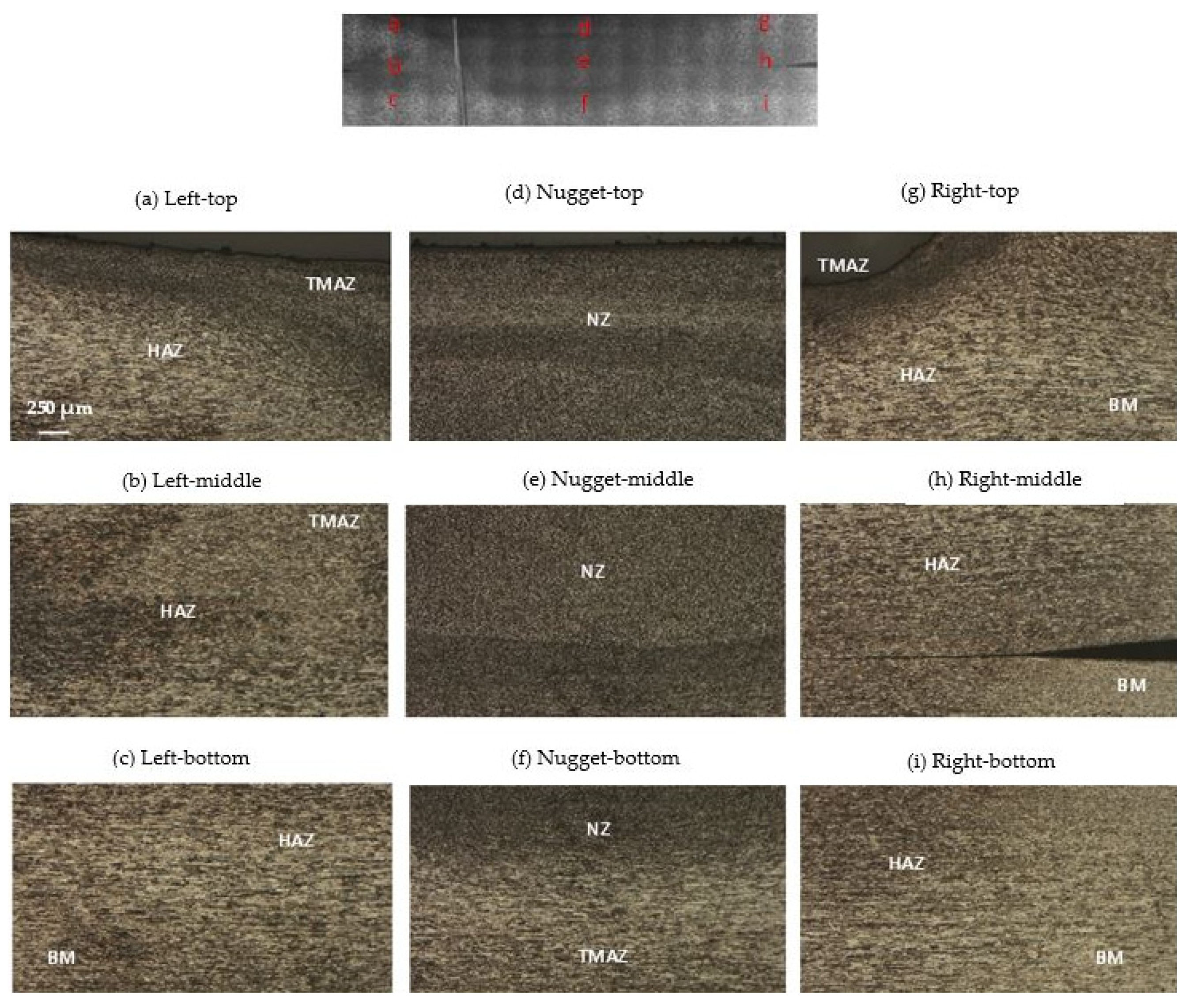
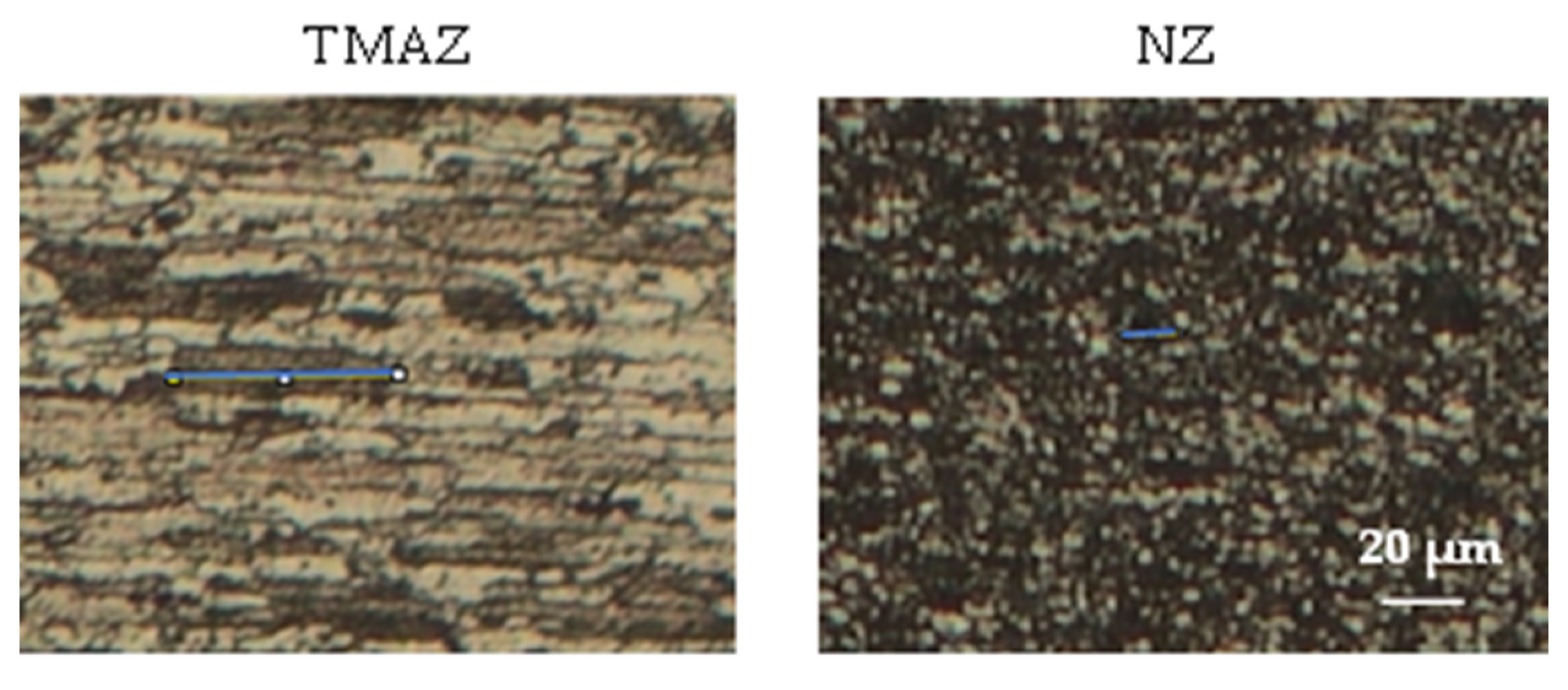
- The nugget zone (NZ) microstructure was characterized by extremely thin, completely reformed equiaxed grains, exhibiting the most significant refinement. In contrast, the thermomechanical-affected zone (TMAZ) consisted of highly distorted and partially recrystallized grain, caused by the elevated temperature and deformation applied by the welding tool. However, the heat-affected zone (HAZ) microstructure, characterized by overgrown grains, was similar to that of the base metal (BM), since the HAZ is only exposed to heat and not to deformations.
- -
- As the welding speed decreased, the NZ grain size increased by a rate ranging from 25% to 33% induced by the overaging effects due to the high temperatures reached during hot welding.
- -
- The ascending trend in TMAZ grain size at hot welding (Vs = 70 mm/min), with a rate ranging from 3% to 5%, compared to cold welding (Vs = 120 mm/min) shows that the generated heat played the main role in FSW rather than plastic deformation.
Author Contributions
Funding
Data Availability Statement
Acknowledgments
Conflicts of Interest
References
- Thomas, W.; Nicholas, E.; Needham, J.; Murch, M.; Temple-Smith, P.; Dawes, C. Friction Stir Butt Welding (The Welding Institute (TWI)). PCT World Patent Application WO 93/10935, 10 June 1993. [Google Scholar]
- Xiao, X.; Mao, Y.; Wang, X.; Qin, D.; Fu, L. Effects of Curvature Direction on Friction Stir Welding Lap Joint of Aluminum Alloy “S” Curved Surface. Int. J. Adv. Manuf. Technol. 2023, 125, 4693–4705. [Google Scholar] [CrossRef]
- Yaduwanshi, D.K.; Rao, C.R.M.; Naidu, S.R.M.; Sakharwade, S.G.; Sharma, S.; Khalkar, V.; Baskar, S.; Kaliyaperumal, G. Thermal Evaluation of Aluminum Welding: A Comparative Study of Friction Stir Welding (FSW), Plasma-Fsw, and Tungsten Inert Gas (TIG)-FSW Techniques. Int. J. Interact. Des. Manuf. (IJIDeM) 2024, 1–13. [Google Scholar] [CrossRef]
- Mirzaei, M.; Asadi, P.; Fazli, A. Effect of Tool Pin Profile on Material Flow in Double Shoulder Friction Stir Welding of AZ91 Magnesium Alloy. Int. J. Mech. Sci. 2020, 183, 105775. [Google Scholar] [CrossRef]
- Alemdar, A.S.A.; Jalal, S.R.; Mulapeer, M.M.S. Influence of Friction Stir Welding Process on the Mechanical Characteristics of the Hybrid Joints AA2198-T8 to AA2024-T3. Adv. Mater. Sci. Eng. 2022, 2022, 7055446. [Google Scholar] [CrossRef]
- Hassanifard, S.; Ghiasvand, A.; Varvani-Farahani, A. Fatigue Response of Aluminum 7075-T6 Joints through Inclusion of Al2O3 Particles to the Weld Nugget Zone during Friction Stir Spot Welding. J. Mater. Eng. Perform. 2021, 31, 1781–1790. [Google Scholar] [CrossRef]
- Lunetto, V.; De Maddis, M.; Russo Spena, P. Similar and Dissimilar Lap Friction Stir Welding of Titanium Alloys: On the Elimination of the Hook Defect. Int. J. Adv. Manuf. Technol. 2023, 126, 3417–3435. [Google Scholar] [CrossRef]
- Babu Rao, T. Stochastic Tensile Failure Analysis on Dissimilar AA6061-T6 with AA7075-T6 Friction Stir Welded Joints and Predictive Modeling. J. Fail. Anal. Prev. 2020, 20, 1333–1350. [Google Scholar] [CrossRef]
- Balakrishnan, M.; Leitão, C.; Arruti, E.; Aldanondo, E.; Rodrigues, D. Influence of Pin Imperfections on the Tensile and Fatigue Behaviour of AA 7075-T6 Friction Stir Lap Welds. Int. J. Adv. Manuf. Technol. 2018, 97, 3129–3139. [Google Scholar] [CrossRef]
- Ge, Z.; Gao, S.; Ji, S.; Yan, D. Effect of Pin Length and Welding Speed on Lap Joint Quality of Friction Stir Welded Dissimilar Aluminum Alloys. Int. J. Adv. Manuf. Technol. 2018, 98, 1461–1469. [Google Scholar] [CrossRef]
- Yuvaraj, K.; Varthanan, P.A.; Haribabu, L.; Madhubalan, R.; Boopathiraja, K. Optimization of FSW Tool Parameters for Joining Dissimilar AA7075-T651 and AA6061 Aluminium Alloys Using Taguchi Technique. Mater. Today Proc. 2021, 45, 919–925. [Google Scholar] [CrossRef]
- Abolusoro, O.P.; Akinlabi, E.T.; Kailas, S.V. Tool rotational speed impact on temperature variations, mechanical properties and microstructure of friction stir welding of dissimilar high-strength aluminium alloys. J. Braz. Soc. Mech. Sci. Eng. 2020, 42, 176. [Google Scholar] [CrossRef]
- Kubit, A.; Bucior, M.; Wydrzyński, D.; Trzepieciński, T.; Pytel, M. Failure Mechanisms of Refill Friction Stir Spot Welded 7075-T6 Aluminium Alloy Single-Lap Joints. Int. J. Adv. Manuf. Technol. 2018, 94, 4479–4491. [Google Scholar] [CrossRef]
- Kubit, A.; Trzepiecinski, T.; Bochnowski, W.; Drabczyk, M.; Faes, K. Analysis of the Mechanism of Fatigue Failure of the Refill Friction Stir Spot Welded Overlap Joints. Arch. Civ. Mech. Eng. 2019, 19, 1419–1430. [Google Scholar] [CrossRef]
- Garg, A.; Raturi, M.; Garg, A.; Bhattacharya, A. Microstructure Evolution and Mechanical Properties of Double-Sided Friction Stir Welding between AA6061-T6 and AA7075-T651. CIRP J. Manuf. Sci. Technol. 2020, 31, 431–438. [Google Scholar] [CrossRef]
- Li, B.; Shen, Y. A Feasibility Research on Friction Stir Welding of a New-Typed Lap–Butt Joint of Dissimilar Al Alloys. Mater. Des. 2012, 34, 725–731. [Google Scholar] [CrossRef]
- Ghiasvand, A.; Suksatan, W.; Tomków, J.; Rogalski, G.; Derazkola, H.A. Investigation of the Effects of Tool Positioning Factors on Peak Temperature in Dissimilar Friction Stir Welding of AA6061-T6 and AA7075-T6 Aluminum Alloys. Materials 2022, 15, 702. [Google Scholar] [CrossRef]
- Yi, D.; Onuma, T.; Mironov, S.; Sato, Y.; Kokawa, H. Evaluation of Heat Input during Friction Stir Welding of Aluminium Alloys. Sci. Technol. Weld. Join. 2017, 22, 41–46. [Google Scholar] [CrossRef]
- Ishak, M.; Noordin, N.; Shah, L. Parametric Studies on Tensile Strength in Joining AA6061-T6 and AA7075-T6 by Gas Metal Arc Welding Process; IOP Publishing: Bristol, UK, 2015; Volume 100, p. 012042. [Google Scholar] [CrossRef]
- Meengam, C.; Sillapasa, K. Evaluation of Optimization Parameters of Semi-Solid Metal 6063 Aluminum Alloy from Friction Stir Welding Process Using Factorial Design Analysis. J. Manuf. Mater. Process. 2020, 4, 123. [Google Scholar] [CrossRef]
- Azimzadegan, T.; Serajzadeh, S. An Investigation into Microstructures and Mechanical Properties of AA7075-T6 during Friction Stir Welding at Relatively High Rotational Speeds. J. Mater. Eng. Perform. 2010, 19, 1256–1263. [Google Scholar] [CrossRef]
- Silva, A.; De Backer, J.; Bolmsjö, G. Temperature Measurements during Friction Stir Welding. Int. J. Adv. Manuf. Technol. 2017, 88, 2899–2908. [Google Scholar] [CrossRef]
- ASTM E384-22; Standard Test Method for Microindentation Hardness of Materials. ASTM International: West Conshohocken, PA, USA, 2022. [CrossRef]
- ASTM E8/E8M-22; Standard Test Methods for Tension Testing of Metallic Materials. ASTM International: West Conshohocken, PA, USA, 2022. [CrossRef]
- Robitaille, B.; Provencher, P.R.; St-Georges, L.; Brochu, M. Mechanical Properties of 2024-T3 AlClad Aluminum FSW Lap Joints and Impact of Surface Preparation. Int. J. Fatigue 2021, 143, 105979. [Google Scholar] [CrossRef]
- Nandan, R.; Roy, G.; Lienert, T.; Debroy, T. Three-Dimensional Heat and Material Flow during Friction Stir Welding of Mild Steel. Acta Mater. 2007, 55, 883–895. [Google Scholar] [CrossRef]
- Verma, S.; Misra, J.P. Effect of Process Parameters on Temperature and Force Distribution during Friction Stir Welding of Armor-Marine Grade Aluminum Alloy. Proc. Inst. Mech. Eng. Part B J. Eng. Manuf. 2021, 235, 144–154. [Google Scholar] [CrossRef]
- Nadikudi, B.K.B.; Davidson, M.; Akasapu, N.R.; Govindaraju, M. Formability Analysis of Dissimilar Tailor Welded Blanks Welded with Different Tool Pin Profiles. Trans. Nonferrous Met. Soc. China 2015, 25, 1787–1793. [Google Scholar] [CrossRef]
- Dong, P.; Li, H.; Sun, D.; Gong, W.; Liu, J. Effects of Welding Speed on the Microstructure and Hardness in Friction Stir Welding Joints of 6005A-T6 Aluminum Alloy. Mater. Des. 2013, 45, 524–531. [Google Scholar] [CrossRef]
- Kumar, A.; Veeresh Nayak, C.; Herbert, M.A.; Rao, S.S. Microstructure and Hardness of Friction Stir Welded Aluminium–Copper Matrix-Based Composite Reinforced with 10 Wt-% SiCp. Mater. Res. Innov. 2014, 18, S6–S84. [Google Scholar] [CrossRef]
- Darzi Naghibi, H.; Shakeri, M.; Hosseinzadeh, M. Neural Network and Genetic Algorithm Based Modeling and Optimization of Tensile Properties in FSW of AA 5052 to AISI 304 Dissimilar Joints. Trans. Indian Inst. Met. 2016, 69, 891–900. [Google Scholar] [CrossRef]
- Aydin, H.; Tutar, M.; Durmuş, A.; Bayram, A.; Sayaca, T. Effect of Welding Parameters on Tensile Properties and Fatigue Behavior of Friction Stir Welded 2014-T6 Aluminum Alloy. Trans. Indian Inst. Met. 2012, 65, 21–30. [Google Scholar] [CrossRef]
- Cabrini, M.; Bocchi, S.; D’Urso, G.; Giardini, C.; Lorenzi, S.; Testa, C.; Pastore, T. Effect of Load on the Corrosion Behavior of Friction Stir Welded AA 7075-T6 Aluminum Alloy. Materials 2020, 13, 2600. [Google Scholar] [CrossRef]
- Manikandan, P.; Prabhu, T.A.; Manwatkar, S.K.; Rao, G.S.; Murty, S.N.; Sivakumar, D.; Pant, B.; Mohan, M. Tensile and Fracture Properties of Aluminium Alloy AA2219-T87 Friction Stir Weld Joints for Aerospace Applications. Metall. Mater. Trans. A 2021, 52, 3759–3776. [Google Scholar] [CrossRef]
- Carlone, P.; Astarita, A.; Rubino, F.; Pasquino, N. Microstructural Aspects in FSW and TIG Welding of Cast ZE41A Magnesium Alloy. Metall. Mater. Trans. B 2016, 47, 1340–1346. [Google Scholar] [CrossRef]
- Topic, I.; Höppel, H.W.; Göken, M. Deformation Behaviour of Accumulative Roll Bonded and Friction Stir Welded Aluminium Alloys; Trans Tech Publcations: Stafa-Zurich, Switzerland, 2008; Volume 584, pp. 833–839. [Google Scholar] [CrossRef]
- Sun, Y.; Fujii, H.; Takada, Y.; Tsuji, N.; Nakata, K.; Nogi, K. Effect of Initial Grain Size on the Joint Properties of Friction Stir Welded Aluminum. Mater. Sci. Eng. A 2009, 527, 317–321. [Google Scholar] [CrossRef]
- Aliha, M.; Shahheidari, M.; Bisadi, M.; Akbari, M.; Hossain, S. Mechanical and Metallurgical Properties of Dissimilar AA6061-T6 and AA7277-T6 Joint Made by FSW Technique. Int. J. Adv. Manuf. Technol. 2016, 86, 2551–2565. [Google Scholar] [CrossRef]


| AA 7075-T6 | ||||||||
|---|---|---|---|---|---|---|---|---|
| Cr | Al | Fe | Mg | Zn | Mn | Si | Cu | Ti |
| 0.029 | Balance | 0.61 | 2.04 | 5.11 | 0.014 | 0.33 | 1.11 | 0.027 |
| Aluminum Alloy | Yield Stress (MPa) | Elongation (%) | UTS (MPa) |
|---|---|---|---|
| AA7075-T6 | 485 | 11 | 568 |
Disclaimer/Publisher’s Note: The statements, opinions and data contained in all publications are solely those of the individual author(s) and contributor(s) and not of MDPI and/or the editor(s). MDPI and/or the editor(s) disclaim responsibility for any injury to people or property resulting from any ideas, methods, instructions or products referred to in the content. |
© 2024 by the authors. Licensee MDPI, Basel, Switzerland. This article is an open access article distributed under the terms and conditions of the Creative Commons Attribution (CC BY) license (https://creativecommons.org/licenses/by/4.0/).
Share and Cite
Toumi, O.; Khalifa, R.B.; Silvestri, A.T.; Ennetta, R.; Scherillo, F.; Prisco, U. Assessment of the Thermomechanical Behavior and Microstructure of AA 7075-T6 Aluminum Alloy Lap Joints at Optimal Predicted FSW Process Parameters. Metals 2024, 14, 839. https://doi.org/10.3390/met14080839
Toumi O, Khalifa RB, Silvestri AT, Ennetta R, Scherillo F, Prisco U. Assessment of the Thermomechanical Behavior and Microstructure of AA 7075-T6 Aluminum Alloy Lap Joints at Optimal Predicted FSW Process Parameters. Metals. 2024; 14(8):839. https://doi.org/10.3390/met14080839
Chicago/Turabian StyleToumi, Oumayma, Romdhane Ben Khalifa, Alessia Teresa Silvestri, Ridha Ennetta, Fabio Scherillo, and Umberto Prisco. 2024. "Assessment of the Thermomechanical Behavior and Microstructure of AA 7075-T6 Aluminum Alloy Lap Joints at Optimal Predicted FSW Process Parameters" Metals 14, no. 8: 839. https://doi.org/10.3390/met14080839