Abstract
Concurrently improving the formability and post-formed strength of Al-Zn-Mg alloy sheets is crucial for producing high-strength parts with complex shapes. A novel process of aging warm-forming (AWF) to form solution heat-treated and water-quenched aluminum alloy sheets is proposed in this paper. The as-quenched AA 7075 sheet was first pre-aged and then formed at the desired temperature. The automotive paint–bake process was then utilized as the second aging step to achieve the target strength of the formed part. Additionally, the post-formed strength and warm formability of specimens under the AWF process conditions, as well as the warm-forming of various heat-treated Al-Zn-Mg alloy sheets proposed in previous studies, were compared through tensile and limit dome height tests. Precipitate characteristics of specimens subjected to different warm-forming process conditions were examined to understand their impact on warm formability. The warm formability of Al-Zn-Mg alloy sheets was significantly enhanced, and the post-formed strength achieved was more than 90% of the strength of as-received AA 7075-T6 sheets under the AWF process condition. The results demonstrated the feasibility of this novel AWF process to manufacture Al-Zn-Mg alloy stamped parts for improved spring-back, formability, and good overall post-formed strength. The results also indicate that microstructural characteristics in Al-Zn-Mg alloy sheets under different warm-forming process conditions have a noticeable influence on warm formability and final mechanical properties.
1. Introduction
The trend of reducing CO2 emissions in gasoline automobiles and enhancing the energy efficiency of electric vehicles through lightweight body design has become increasingly prominent in the automotive industry over the past decade. With excellent properties such as a high strength-to-weight ratio and recycling rate, Al-Zn-Mg alloys have emerged as promising candidates to replace steel structural parts that demand a higher level of strength to satisfy impact safety standards [1]. However, the application of this high-strength aluminum alloy, particularly in the production of products with complex shapes, is limited due to poor formability and severe spring-back at room temperature. Several forming processes to overcome this limitation have been proposed by enhancing the formability of high-strength aluminum alloys at elevated temperatures [2].
Warm-forming a peak-aged (T6) Al-Zn-Mg alloy sheet at temperatures ranging from approximately 180 °C to 250 °C is a process for manufacturing lightweight structural parts. This process has attracted attention from automotive parts manufacturers due to its ability to enhance formability while maintaining sufficient strength within this temperature range, e.g., the BMW-i8 door beam [3]. However, the strength of as-formed parts is reduced due to the coarsening of precipitates during the warm-forming process [4], and the effect becomes more pronounced after the paint–bake (PB) treatment [5].
Several studies have proposed new processes to prevent the over-aging of post-formed parts by considering the influence of the PB treatment on the warm-forming process and utilizing under-aged aluminum alloy sheets for warm forming. Ivanoff et al. [6] conducted research aimed at overcoming strength loss in AA 7075-T6 warm-formed parts by combining characteristics of retrogression–re-aging treatment and the warm-forming process of high-strength aluminum alloy. The strength loss of warm-formed parts was attributed to the retrogression of AA7075-T6, while the subsequent strength recovery in the PB response was considered as re-aging. It was discovered that the strength loss in warm-formed parts, following the PB process, was kept within 5% of that of the received T6 sheets through the appropriate selection of warm-forming parameters. Österreicher et al. [7] and Lin et al. [8] investigated the warm-forming process of AA 7075 sheets, which were pre-aged at temperatures ranging from 65 °C to 130 °C, along with pre-aging treatment parameters, warm-forming conditions, and subsequent PB response. The results indicated that the strength of AA 7075 warm-formed parts reached approximately 95% of that of received T6 sheets through the combination of suitable pre-aging treatment, warm-forming process parameters, and PB response. Furthermore, it was discovered that pre-aged AA 7075 sheets exhibited superior warm formability compared to AA 7075-T6 sheets under identical forming conditions.
It appears to be efficient to enhance the warm-forming process through the mechanism of multi-step aging treatment. However, the mechanism causing differences in formability at elevated temperatures among sheets treated with various aging processes has not been addressed in previous literature. In this paper, a novel aging warm-forming process for Al-Zn-Mg alloy sheets is proposed based on the concept of multi-step aging treatment. The final mechanical properties of the simulated aging warm-forming (AWF) processing procedure are examined through uniaxial tensile tests under room temperature (RT). The warm formability of the proposed process is evaluated through limit dome height tests, and the plastic flow behaviors of Al-Zn-Mg alloy sheets under the AWF process condition were estimated using warm tensile tests. Additionally, final strength and formability tests under retrogression re-aging warm-forming (RRAWF) and pre-aging warm-forming (PAWF) processes in previous studies are assessed. Transmission electron microscopy is used to analyze the characteristics of the microstructure under different warm-forming processes before and after PB treatment. Finally, the formability at elevated temperatures of Al-Zn-Mg alloy sheets treated under various aging processes will be evaluated, and the feasibility of the novel AWF process proposed in this paper will also be explored.
2. Material and Experimental Methods
2.1. Material and Specimen Design
AA 7075-T6 sheet material with a 2 mm thickness, which is the representative Al-Zn-Mg alloy sheet for applications of high-strength aluminum stamped parts, was chosen for use in the research. The sheets were supplied by Austria Metall AG (AMAG) Company, (AMAG, Ranshofen, Austria) and the composition specifications of AA 7075 are shown in Table 1. Rectangular specimens measuring 110 mm × 80 mm were prepared to simulate the thermal history of pre-processing procedures, while round samples with a diameter of 100 mm were prepared for the limit dome height test.

Table 1.
Chemical composition of high-strength aluminum alloy (mass contents in %; Bal. = Balance).
2.2. Experimental Details
2.2.1. AWF Processing Procedure
First, specimens were solution heat treated (SHT) at 480 °C ± 5 °C for 5 min, then water quenched to room temperature (RT) to acquire W-tempered specimens. The heating time to SHT temperature was controlled to 12 min for each specimen. To prevent the occurrence of nature aging, W-tempered specimens were stored at RT less than 30 min.
Subsequently, W-tempered specimens were rapidly heated (heating time: 30 s) to the target temperature of 180 °C for 1 min, followed by die cooling to simulate the thermal history in the aging warm-forming process. Based on a previous study by Jiang et al. [9], it was shown that W-tempered specimens subjected to a short-term pre-aging treatment at 180 °C, followed by subsequent PB conditions, can achieve a final component strength comparable to that of the as-received AA 7075-T6 sheet material. Therefore, 180 °C was chosen as the target forming temperature for the AWF process in this research. Finally, die-cooled specimens were subjected to a simulated PB treatment at 185 °C for 20 min. A schematic illustration of the AWF process is presented in Figure 1a.
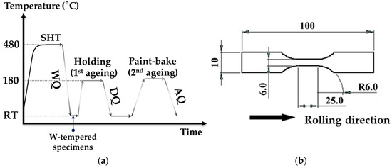
Figure 1.
(a) Schematic illustration of aging warm-forming process; (b) Dimensions of tensile test specimen (unit: mm).
Specimens with a gauge length of 25 mm were machined from the processing procedure and as-received T6 specimens, with the principal axis aligned in the rolling direction. Figure 1b shows the design of tensile specimens according to the ASTM sub-sized standard. The mechanical properties of specimens after AWF and PB treatments were evaluated through uniaxial tensile tests conducted at room temperature with a strain rate of 0.01/s.
2.2.2. Formability and Flow Behavior of Aging Warm-Forming Process
The formability of the AWF specimens was evaluated through a limit dome height (LDH) test on an 80-ton hydraulic press (Amino UTM-855, Shizuoka Prefecture, Japan). The forming tooling system (Figure 2a) was first heated to the target forming temperature of 180 °C utilizing installed electric resistance heating cartridges. It was also equipped with thermocouples for tooling temperature control. Graphite lubricant, commonly used as a lubricant under elevated forming conditions for aluminum alloys, was brushed on forming tools before experiments were performed. The specimen was transferred into the forming tooling system within 30 min after being SHT and water quenched. Subsequently, it was heated to the desired temperature of 180 °C rapidly in contact with forming tools (heating rate: 3 °C/s) and soaked for the target time of 1 min. The warm LDH test then started with a punch speed of 1.5 mm/s and blank holder pressure of 145 bar with a draw-bead to prevent material from flowing into the die cavity.
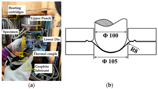
Figure 2.
Forming tooling system of LDH test, (a) photo of forming tooling system; (b) geometry of tooling system (unit: mm).
To further investigate the plastic flow behaviors of Al-Zn-Mg alloy sheets under AWF conditions, warm tensile tests were also carried out on the Gleeble® 3500-GTC system (Dynamic Systems Inc., Poestenkill, NY, USA). Warm tensile specimens with a gauge length of 20 mm and a width of 10.28 mm (Figure 3a) were cut from AA 7075-T6 with the principal axis aligned in the rolling direction, solution heat-treated, and water quenched. Subsequently, deformation was started after heating specimens to 180 °C with a heating rate of 3 °C/s and holding for a minute, as shown in Figure 3b. These parameters were chosen to simulate the heating of specimens in the forming limit test tooling system. The heating rate was controlled by a thermocouple welded onto the center of the reduction area of the tensile specimen. Warm tensile tests were conducted at strain rates of 0.1/s, 1/s, and 5/s strain rate sensitivity tests. A photograph of the setup is shown in Figure 3c.
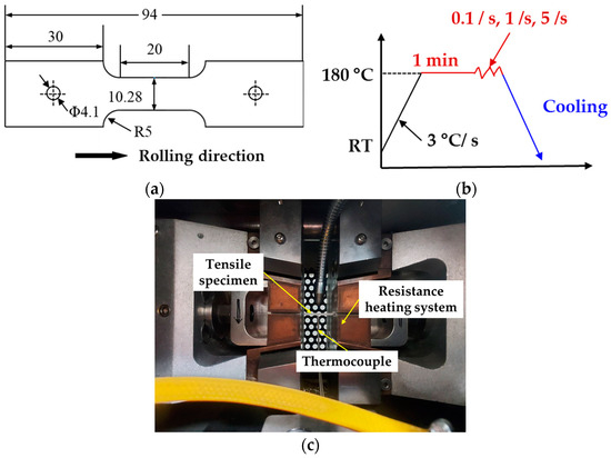
Figure 3.
Experimental setup of warm tensile test, (a) dimensions of warm tensile test specimen (unit: mm); (b) schematic of warm tensile tests; (c) photo of the warm tensile test system.
The simulated processing procedure, warm formability, and warm tensile tests were also implemented for the retrogression–re-aging warm-forming (RRAWF) and pre-aged warm-forming (PAWF) processes. These tests were conducted under the optimal process conditions (Table 2) of RRAWF [6] and PAWF [7] proposed in previous studies. Under these conditions, superior warm formability was achieved, and the final component strength was controlled within a 10% loss compared to the as-received AA 7075-T6 sheets. These results were compared with those obtained from the AWF process. At least five repeats for each test were carried out to ensure consistency.
Table 2.
Parameters of experimental tests under different processing procedures.
2.2.3. Differential Scanning Calorimetry
DSC samples with dimensions of 3 mm (length) × 3 mm (width) × 2 mm (thickness) were cut from simulated AWF, PAWF, and RRAWF simulated processing procedure specimens and cleaned with ethanol. The DSC tests were conducted on a TA Instruments Q20 Differential Scanning Calorimeter (TA Instruments, New Castle, DE, USA) by heating samples from room temperature to 600 °C at a heating rate of 10 °C/min. The precipitation states of specimens from different warm-forming procedures were preliminarily understood through DSC analysis. For comparison, as-received AA 7075-T6 samples were also prepared for testing.
2.3. Microstructure Examination
Samples taken from the as-received AA 7075-T6 and AWF, PAWF, and RRAWF simulated processing procedures specimens (both before and after PB treatment) were first ground to a thickness of ~70 μm, and then disks with a diameter of 3 mm were punched. After that, these discs were electro-polished in a Double Jet Polisher (E.A. Fischione Instruments, Inc., Export, PA, USA) at −20 °C and an operating voltage of 12 V with an electrolyte consisting of a mixture of 33% concentrated nitric acid and 67% methanol until they became electron-transparent. Microstructure examinations of specimens were conducted utilizing a transmission electron microscope JEOL JEM 2100 F (Japan Electron Optics Laboratory Co., Tokyo, Japan). In addition, the grain structure of specimens under different warm-forming processing procedures was evaluated via electron backscatter diffraction (EBSD) analysis using a HITACHI Regulus 8100 field emission scanning electron microscope (SEM) (Hitachi High-Tech Co., Tokyo, Japan). The microstructural examination of specimens under simulated processing procedure conditions is shown in Table 3.
Table 3.
Simulated processing procedure conditions for DSC, TEM, and EBSD analysis.
3. Results
3.1. Flow Behaviour of Al-Zn-Mg Sheets under AWF Process
The flow behavior of Al-Zn-Mg sheets under AWF, PAWF, and RRAWF process conditions with strain rates of 0.1/s, 1/s, and 5/s was evaluated through warm tensile tests. The obtained true stress–strain curves are presented in Figure 4a–c, and true uniform elongation is illustrated in Figure 4d. The results indicate that specimens under the AWF process condition exhibit superior ductility, followed by PAWF and, finally, RRAWF. Moreover, the result is not affected by the studied range of strain rates.
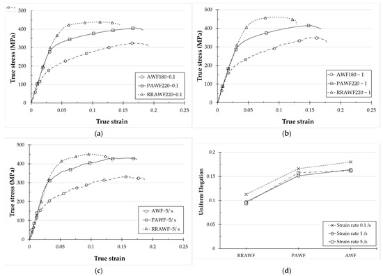
Figure 4.
The stress–strain curve with strain rates of (a) 0.1/s, (b) 1/s, (c) 5/s, and (d) true uniform elongation of Al-Zn-Mg sheets under AWF, PAWF, and RRAWF processes.
The plastic anisotropy of Al-Zn-Mg alloy sheets under different strain rates for AWF, PAWF, and RRAWF process conditions was further evaluated based on Lankford coefficients R-value [10], which were determined using the following equation:
where and are the true strain in the width and thickness direction, respectively. Lankford coefficients determined under different strain rates for AWF, PAWF, and RRAWF process conditions are illustrated in Table 4. The highest value is achieved under the AWF process condition, followed by PAWF and RRAWF, and it slightly increases with strain rates.
Table 4.
Lankford coefficients under different strain rates for AWF, PAWF, and RRAWF process.
To investigate strain hardening characteristic and strain rate sensitivity of Al-Zn-Mg alloy sheets under AWF, PAWF, and RRAWF process conditions, we determined true stress–strain curves utilizing the extended Hollomon equation [11] as follows:
where σ is true flow stress, ε is true plastic strain, and is the strain rate. n represents the work-hardening exponent, indicating the work-hardening degree under the same plastic deformation, m is the strain rate sensitivity exponent, and K is the strength coefficient.
Calculated n-value and m-value are shown in Figure 5a and Figure 5b, respectively. It shows that the highest n value is achieved under the AWF process condition, followed by PAWF and RRAWF, and the result is not affected by the studied range of strain rates. The results of the n-value show similar trends with uniform elongation and Lankford coefficients. It is known that strain hardening prevents early necking, and higher n-values have a positive effect on formability [7]. The m-values obtained under different strain rates for AWF, PAWF, and RRAWF process conditions fall within the range of 0.015~0.025. This result indicates that under these three forming process conditions, the material exhibits low strain rate sensitivity, with deformation behavior closely resembling that observed in cold-forming processes of sheet metal. The deformation behavior across the studied range of strain rates for the AWF, PAWF, and RRAWF process condition corresponds with the strain rate-forming temperature deformation mechanism map [12]. The results of the m-value also show similar trends with uniform elongation and Lankford coefficients. It can be inferred that Al-Zn-Mg alloy sheets have the best formability subjected to the AWF process condition, and the influence of the studied range of strain rates on this outcome is negligible.
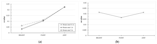
Figure 5.
(a) Strain hardening exponent; (b) strain rate sensitivity exponent of Al-Zn-Mg alloy sheets under different strain rates for AWF, PAWF, and RRAWF process conditions.
The true strain–stress curve of as-received AA 7075-T6 specimens under a strain rate of 0.01/s at RT and a strain rate of 5/s at the AWF process condition is further compared and shown in Figure 6. It can be seen that under the AWF process condition, even at a higher strain rate of 5/s, the elongation is still higher compared to the as-received AA 7075-T6 at a relatively low strain rate of 0.01/s. This demonstrates that the formability of Al-Zn-Mg alloy sheets can be significantly enhanced under AWF process conditions.
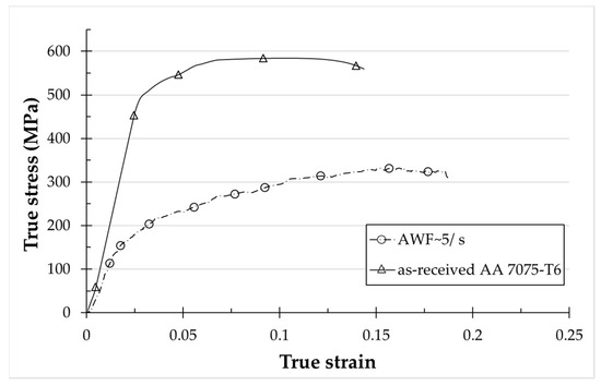
Figure 6.
True strain–stress curve of as-received AA 7075-T6 specimens under a strain rate of 0.01/s at RT and specimens under the AWF process condition with a strain rate of 5/s.
3.2. Spring-Back Analysis of Al-Zn-Mg Sheets under the AWF Process
The spring-back of Al-Zn-Mg alloy stamped parts can significantly affect the precision of vehicle body assembly. Analyzing the spring-back behavior of specimens under the AWF process condition is highly important. Based on the research from the previous literature [13], spring-back in Al-Zn-Mg alloy sheets is related to the Young’s modulus and strength. A comparison of Young’s modulus obtained from warm-forming tensile tests under different strain rates for AWF, PAWF, and RRAWF process conditions was conducted, as shown in Figure 7.
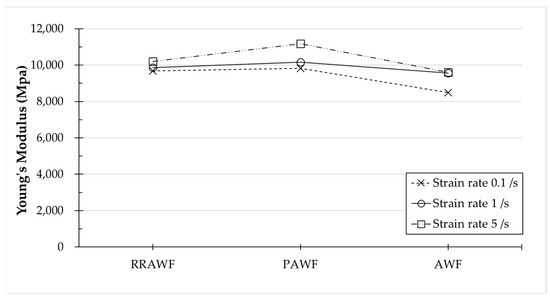
Figure 7.
Young’s modulus obtained from warm-forming tensile tests under different strain rates for AWF, PAWF, and RRAWF process conditions.
Young’s modulus of PAWF and RRAWF process conditions are similar. However, it is also evident that the strength of the material is much lower under the PAWF process condition from the stress–strain curves. It is known that the elastic strain is positively correlated to the degree of spring-back when the material has a similar Young’s modulus but lower strength. Therefore, components formed under RRAWF conditions exhibit more pronounced spring-back compared to those formed under PAWF conditions. Under the AWF process condition, Young’s modulus is lower compared to PAWF and RRAWF. However, the markedly reduced strength under the AWF process condition complicates direct comparisons of spring-back with the other two process conditions.
Further investigation was carried out by calculating the spring-back elastic strain under the assumption of ideal unloading behavior, as determined by the following equation:
where σ is true stress, selected at a true strain of 0.08 under different strain rates for AWF, PAWF, and RRAWF process conditions. E is Young’s modulus. The results are illustrated in Table 5.
Table 5.
Calculated spring-back elastic strain under different strain rates for AWF, PAWF, and RRAWF process conditions with σ chosen at a true strain of 0.08.
The findings reveal that specimens subjected to the AWF process condition exhibit the lowest elastic strain, followed by those subjected to the PAWF and RRAWF conditions, respectively. Notably, the results are not affected by the studied range of strain rates. It can be concluded that Al-Zn-Mg alloy sheets processed under AWF conditions result in stamped components with reduced spring-back, thereby enabling more effective control of dimensional accuracy.
3.3. Warm Formability of Al-Zn-Mg Sheets under the AWF Process
The LDH test is considered an effective measurement for determining formability in sheet metal forming. As-received T6 and W-temper specimens were formed using the LDH forming tooling system at room temperature and were compared with the warm formability of specimens subjected to AWF, PAWF, and RRAWF process conditions. LDH values from different forming conditions are revealed in Figure 8. The formability of specimens under all warm-forming conditions is significantly improved in comparison with the LDH value of the T6 specimen at RT. However, the LDH values of PAWF and RRAWF showed a minimal difference from that of the W-temper at RT. The maximum LDH value of 22.1 mm achieved under the AWF process condition is 10–15% higher than those obtained under the PAWF and RRAWF process conditions. The result indicates that the formability of Al-Zn-Mg alloy sheets can be substantially improved by the AWF process.
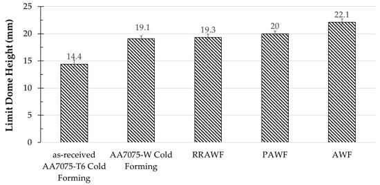
Figure 8.
LDH values of specimens under the AWF, PAWF, and RRAWF process conditions. LDH values of as-received T6 and W-tempered specimens at RT are also included for comparison.
3.4. Final Mechanical Properties
The mechanical properties of as-received T6 specimens and specimens of different warm-forming processing procedures are presented in Figure 9.
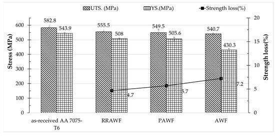
Figure 9.
Final mechanical properties of specimens subjected to AWF, PAWF, and RRAWF process conditions. Mechanical properties of as-received T6 are included for comparison.
The as-received Al 7075-T6 yield strength (YS) is 540 MPa, and the ultimate tensile strength (UTS) is 580 MPa. Compared to as-received specimens, specimens of different warm-forming procedures show a 4~10% loss of the UTS.
The YS and UTS of specimens subjected to the AWF process condition are 430.9 MPa and 540.7 MPa, respectively, which achieves approximately 93% of the initial UTS of the as-received T6 specimen. The final mechanical properties are also further compared to those of PAWF and RRAWF specimens. The UTS of specimens for different warm-forming process conditions show little difference. However, the YS of the AWF specimens is significantly lower than that under other warm-forming conditions. This difference might be attributed to the microstructural evolution induced by the varying warm-forming conditions.
3.5. Microstructural Observation
3.5.1. EBSD
The effects under the AWF, PAWF, and the RRAWF process conditions on the grain sizes were analyzed using EBSD measurements. Figure 10 shows the EBSD images (Band contrast [BC] + inverse pole figure [IPF] + Grain boundaries [GB]) of specimens under different warm-forming process conditions. The grain size of as-received AA 7075-T6 sheets was measured at 7.3 μm. Specimens subjected to AWF, PAWF, and RRAWF process conditions exhibited grain sizes of 7.6 μm, 8.7 μm, and 6.4 μm, respectively. The grain sizes exhibit minimal variation under different warm-forming process conditions.
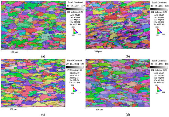
Figure 10.
EBSD micrographs (BC+IPF+GB maps) of (a) as-received AA 7075-T6 sheets and specimens under (b) AWF, (c) PAWF, and (d) RRAWF process conditions.
3.5.2. Microstructures before PB Treatment
Figure 11a1–c1 shows TEM dark field (DF) images of samples from specimens under AWF, PAWF, and RRAWF process conditions without simulated PB treatment. For both samples under RRAWF and PAWF process conditions (Figure 11a1,b1) shows uniformly and evenly distributed platelet and rod precipitates in the matrix with average matrix precipitates (MPts) size of 7.1 nm and 6.2 nm, respectively. However, the MPts morphology of samples from specimens under the AWF process condition (Figure 11c1) shows spherical and platelet precipitates evenly distributed in the matrix with average MPts of 5.3 nm. It differs significantly from the samples of specimens under the PAWF and RRAWF process conditions.
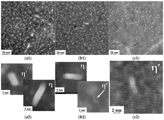
Figure 11.
TEM DF images and HRTEM images in the [110]Al zone axis of specimens under (a1,a2) RRAWF; (b1,b2) PAWF (the arrow indicates the presence of η′ precipitates); (c1,c2) AWF process conditions before PB treatment.
High-resolution TEM (HRTEM) was used for further observation to clarify the main precipitates in the matrix of samples, as shown in Figure 11a2–c2. Figure 11a2,b2 reveals that the main MPts of samples under RRAWF and PAWF process conditions are identified as η′ and η phases. Dissimilar phases are seen in the HRTEM image of samples under the AWF process condition (Figure 11c2). The main MPts of samples are identified to be GP zones and η′ phases.
3.5.3. Microstructures after PB Treatment
TEM DF images and HRTEM images of as-received T6 specimens and specimens under AWF, PAWF, and RRAF process conditions following simulated PB treatment are shown in Figure 12. For the as-received T6 specimen, the MPts with a size of ~6.9 nm are uniformly distributed in the matrix. Compared to corresponding specimens without simulated PB in Figure 11, PB treatment has some impact on the characteristics of microstructures. For specimens under the RRAWF process condition, the coarsened mean size of MPts has been observed to be 10.2 nm. The mean size of MPts subjected to the PAWF process condition, at 5.2 nm, shows nearly no difference compared to before the simulated PB treatment. However, the HRTEM images reveal that, in addition to the η′ and η phases, some GP zones also precipitate in the matrix after the PB treatment. After the PB process, the mean size of MPts at 4.5 nm is evenly distributed within the matrix for the AWF process samples, as shown in Figure 12d2. More precipitates are observed in the matrix after the PB treatment. This indicates that there is further precipitation of more precipitates in the matrix after the PB treatment.
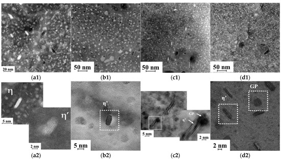
Figure 12.
TEM DF images and HRTEM images in the [110]Al zone axis of specimens under (a1,a2) as-received T6 sheets; (b1,b2) RRAWF; (c1,c2) PAWF; (d1,d2) AWF process conditions after PB treatment.
3.6. Results of DSC Tests
Figure 13 shows DSC curves of as-received T6 specimens and specimens under AWF, PAWF, and RRAWF process conditions after simulated PB treatment. The results were analyzed in conjunction with microstructure examinations in Section 3.4. From the DSC results of a previous study [14], it was found that the formation of GP zones, η′ phases, and η phases correspond to exothermic peaks around temperature intervals of 20–120 °C, 120–250 °C, and 150–300 °C, respectively. The endothermic peaks around temperature intervals of 50–150 °C, 200–250 °C, and 300–350 °C correspond, respectively, to their dissolution.
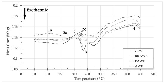
Figure 13.
DSC results of as-received T6 and specimens subjected to AWF, RRAWF, and PAWF process conditions.
The DSC curve of the as-received T6 specimen shows 3 main typical effects marked “2” to “4” in the temperature range. Peak “2” around 200 °C can be related to the dissolution of η′ phase. It is very significant since η′ phases are the primary strengthening phase in as-received AA 7075-T6 sheets. Peak “3” around 260 °C is reported to indicate the transformation into coarser η phases. Broad endothermic peak “4” between 310 °C and 450 °C is considered to correspond to the dissolution of η phases.
The DSC curves of RRA and PA warm-forming specimens show a similar trend to that of the T6 specimen but with some noticeable changes. The temperature of peak “2c” is higher than peak “2” due to coarsening η′ phases under the RRAWF process condition. It is interesting to note that a broad endothermic peak “1a” between 75 °C and 125 °C appears in the specimen’s curve under the AWF process condition. The peak is related to the dissolution of GP zones. This indicates the presence of GP zones within the AWF specimen, which is highly consistent with the observations from TEM and HRTEM.
4. Discussion
GP zones and the η′ phase are widely recognized as primary strengthening phases of Al-Zn-Mg alloys [15]. Fine GP zones and η′ phase precipitation follow a sequential process during aging [16]: supersaturated (SSSS) → GP zones → metastable η′ phase (MgZn2) → stable η phase (MgZn2). According to the precipitation theory proposed by Chemingui et al. [17], the nucleation and distribution density of precipitates like the η′ phase are closely related to the nucleation of GP zones. This suggests that GP zones act as critical precursors to the formation of η′ phases. The nucleation of GP zones typically requires several hours at temperatures ranging from 107 to 120 °C [18]. At higher aging temperatures, the nucleation time of GP zones can be shortened, potentially leading to changes in precipitation morphology. Werenskiold et al. [19] indicated that GP zones below a critical size dissolve in the matrix, while those above the critical size remain and transform into η′ phases. This provides a clear explanation of the microstructure morphology of specimens subjected to the AWF process before PB treatment, showing quantitative GP zones and a small number of η′ phases are observable within the matrix, as depicted in Figure 11c1,c2.
Figure 4 illustrates the flow behavior of Al-Zn-Mg alloy sheets subjected to different strain rates for AWF, PAWF, and RRAWF process conditions. The results indicate that Al-Zn-Mg alloy sheets exhibit work-hardening behavior under all warm-forming process conditions. The work-hardening behavior is known to be influenced by key factors such as precipitates, grain size, and solute atoms. Grain sizes of specimens subjected to the AWF, PAWF, and RRAWF conditions, obtained via EBSD analysis, were determined to be in the range of 6–9 μm. The variations in grain sizes are insufficient to impact work-hardening [20] significantly and are, therefore, considered negligible. To further validate the influence of precipitates on work-hardening behavior, graphs illustrating the relationship between precipitate number density and average precipitate size, as well as the n-value, are presented.
Figure 14 illustrates the relationship between the n-value and the number density of MPts, demonstrating an exponential increase in the n-value as the precipitate number density rises. Corresponding TEM analysis results prior to simulated PB treatment (Table 6) indicate that the AWF process condition has the highest precipitate number density in the matrix, followed by PAWF and RRAWF. The result elucidates why the AWF process condition exhibits the highest n-value of flow behavior under different warm-forming process conditions. It is well-established that an increase in dislocation density contributes to work-hardening [21]. The rise in the n-value with the number density of precipitates can be attributed to pre-existing precipitates within the matrix, which act as obstacles for mobile dislocations and promote the multiplication of dislocations in the surrounding matrix [22].
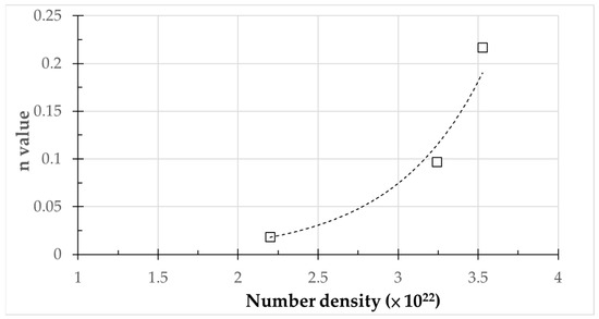
Figure 14.
Relationship between the n-value and the number density of MPts.
Table 6.
Statistic results about MPts and number of density of specimens under AWF, PAWF, and PAWF before simulated PB treatment.
The relationship between the n-value and the average size of MPts is illustrated in Figure 15. It demonstrates that the n-value decreases with an increase in average MPts size. TEM analysis results prior to simulated PB treatment (Table 6) indicate that the AWF process condition has the smallest average size of MPts, followed by PAWF and RRAWF. The result clearly elucidates the highest n-value of flow stress behavior exhibited under the AWF process condition. Bahrami et al. [23] observed that the work-hardening behavior decreases with an increase in the average precipitate radius until reaching a minimum radius when the specimen is in the under-age regime due to the annihilation process (dynamic recovery) becoming more difficult because dislocations must first pass through precipitates to annihilate each other. Since specimens undergoing AWF, PAWF, and RRAWF process conditions [24] are classified as being in the under-aged state, it provides a clear explanation of the relationship between the n-value and the average size of MPts.
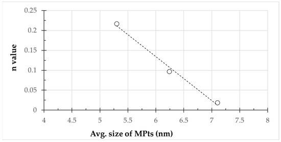
Figure 15.
Relationship between the n-value and average size of MPts.
The work-hardening exponent has been demonstrated in previous studies to exhibit a clear relationship with formability capacity, suggesting that higher n-values may correspond to improved formability [25]. The relation of work-hardening behavior to the formability of Al-Zn- Mg alloys under AWF, PAWF, and RRAWF process conditions has been studied. Figure 16 shows that the LDH value and the n-value exhibit linearly correlated growth in the study. Based on the observed correlation between n-value, precipitate morphology, and LDH values, it can be hypothesized that the varying formability of sheet metal under different warm-forming processes is primarily influenced by the characteristics of pre-existing precipitates in the matrix. Subsequent research will be conducted by examining the connection between the forming limit diagrams for Al-Zn-Mg alloy sheets obtained under AWF, PAWF, and RRAWF process conditions and the quantitative and qualitative analyses of pre-existing precipitates in the sheets. The relationship between these precipitates and the formability of the alloy sheets will be further investigated, and a predictive formability model for Al-Zn-Mg alloy sheets at elevated temperatures with different microstructural characteristics can be constructed to establish a process window for processing design.
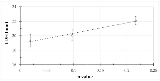
Figure 16.
Relationship between the n-value and LDH value.
The final ultimate tensile strength of specimens under the AWF process achieved a 10% loss controlled to as-received AA 7075-T6 specimens, as shown in Figure 9. However, the yield strength is much lower than that of the as-received AA 7075-T6. Since precipitation strengthening dominates the hardening mechanism of Al-Zn-Mg alloy, according to the precipitation hardening mechanism, the strengthening effect of precipitates on the yield strength can be expressed by the following equation [26]:
where c is an alloy constant; f and r are the volume fraction and average size of MPts, respectively. According to the equation, the strengthening effect of precipitates on yield strength is enhanced with a reduction in the average size of MPts. Although the precipitate size in AWF-treated samples is smaller than those in as-received AA 7075-T6 specimens (as shown in Table 7), the volume fraction of precipitates, indicated by their number density and average size, is significantly higher in the T6 specimens. The discrepancy leads to a notable reduction in strength in the samples processed under the AWF process condition.
Table 7.
Statistic results about MPts and number of density of specimens under AWF, PAWF, and PAWF after simulated PB treatment.
Based on the overall microstructure examination of samples under the AWF process before (Figure 11c1,c2, Table 4) and after PB treatment (Figure 12d1,d2, Table 5), it is evident that the number density of precipitates increases, indicating further precipitation occurs after the PB treatment. This is in good agreement with results found by Österreicher et al. [7], which show that combining pre-aging with PB treatment can lead to secondary precipitation and achieve the desired strength. However, it still did not achieve a favorable distribution of η′ phases in T6 specimens. Large quantities of GP zones are still present within the matrix of samples under the AWF process. Optimization of the parameters for the aging warm-forming process is still required. From previous research [27], it was observed that dynamic precipitation and DSA (dynamic strain aging) stress emerge during the deformation of Al-Zn-Mg alloy sheets, influenced by strain rate, significantly affecting the forming behavior. It should be noted that the effects of dynamic precipitation, DSA, and dislocations introduced [28] during warm-forming on the final mechanical properties have not been considered in this study. Further investigation is needed, as these effects might influence flow behavior and contribute to improving the strength of parts formed under the AWF process condition. The research integrating precipitation kinetics models to predict microstructure characteristics under different AWF parameters [29], along with prediction models for mechanical properties based on microstructural characteristics [30], is currently underway to identify AWF process parameters that meet the mechanical properties of the final product. It will be possible to incorporate the previously mentioned predictive formability model incorporating pre-existing precipitates for Al-Zn-Mg alloy sheets in future works. The optimal AWF process parameters can be determined at the process design stage, thus ensuring that both the structural integrity and desired shape of the component are achieved.
5. Conclusions
A novel aging warm-forming process of Al-Zn-Mg alloy sheets was conducted through experimental investigation. The W-tempered Al-Zn-Mg alloy specimens were initially subjected to a pre-aging treatment at specified conditions before being warm-formed at the same temperature. Simulated PB treatment then served as the second aging step in order for the formed part to achieve the target mechanical properties. In addition, proposed RRA and PA warm-forming processes from previous studies were also involved in the comparison. The conclusions are as follows:
- The ultimate tensile strength (UTS) of the specimen treated with the proposed aging warm-forming processing procedure achieved approximately 93% of AA7075-T6. A good PB response was observed due to the secondary precipitation of pre-existing precipitates in AWF specimens.
- True uniform and fracture elongation, as well as the maximum LDH value, were significantly enhanced under the AWF process compared with the RRA and PA warm-forming processes. The formability of Al-Zn-Mg alloy sheets showed significant improvement. This is primarily attributed to the characteristics of pre-existing precipitates in the matrix in specimens subjected to AWF, RRA, and PA (pre-aging) warm-forming processes.
- The obtained results demonstrate the feasibility of the proposed novel AWF process to manufacture Al-Zn-Mg alloy parts due to improved spring-back response, formability, and good overall post-formed strength. It shows potential application in manufacturing Al-Zn-Mg alloy sheet metal parts. However, there is still room for refinement in this process.
Further research is needed to improve AWF process parameters to achieve the desired component quality in the future. It may be focused on the following:
- Establishing a predictive formability model for Al-Zn-Mg alloy sheets under elevated temperatures based on the relationship between microstructural characteristics and forming limit diagrams obtained under AWF, PAWF, and RRAWF process conditions.
- Identifying AWF process parameters to meet the mechanical properties of the final product by integrating precipitation kinetics models with prediction models for mechanical properties based on microstructural characteristics.
It is possible to establish an optimal AWF process window during the process design phase by integrating the two aforementioned strategies. This approach effectively ensures that both the desired geometrical configuration of the final product and the requisite mechanical strength of the component are simultaneously achieved.
Author Contributions
Conceptualization, W.-L.C. and R.-S.L.; methodology, W.-L.C. and R.-S.L.; software, W.-L.C.; validation, W.-L.C.; formal analysis, W.-L.C.; investigation, W.-L.C.; resources, W.-L.C.; data curation, R.-S.L.; writing—original draft preparation, W.-L.C.; writing—review and editing, R.-S.L.; visualization, W.-L.C.; supervision, R.-S.L.; project administration, W.-L.C. and R.-S.L.; funding acquisition, W.-L.C. All authors have read and agreed to the published version of the manuscript.
Funding
This research received no external funding.
Data Availability Statement
The original contributions presented in the study are included in the article, further inquiries can be directed to the corresponding author.
Acknowledgments
The authors would like to express sincere thanks to the Metal Industries Research and Development Centre (MIRDC) for the equipment and technical report and to Jong Shing Bow from Integrated Service Technology Inc. for the great support for the microstructure observation in this study.
Conflicts of Interest
The authors declare no conflicts of interest.
References
- Raugei, M.; Fakir, O.E.; Wang, L.; Lin, J.; Morrey, D. Life cycle assessment of the potential environmental benefits of a novel hot forming process in automotive manufacturing. J. Clean. Prod. 2014, 83, 80–86. [Google Scholar] [CrossRef]
- Scharifi, E.; Yardley, V.A.; Weidig, U.; Szegda, D.; Lin, J.; Steinhoff, K. Hot sheet metal forming strategies for high-strength aluminum alloys: A review—Fundamentals and applications. Adv. Eng. Mater. 2023, 25, 2300141. [Google Scholar] [CrossRef]
- AMAG Austria Metall AG. AluReport: Safety and Lightweight Construction with AMAG Aluminium; AMAG: Ranshofen, Austria, 2014. [Google Scholar]
- Gronostajski, Z.; Polak, S.; Jaśkiewicz, K.; Kaczyńskia, P.; Skwarski, M.; Krawczyk, J.; Chorzępa, W.; Śliz, K.; Uzar, S. Properties of B-pillar made of aluminium 7075 in warm forming process. Procedia Manuf. 2019, 27, 98–103. [Google Scholar] [CrossRef]
- Kumar, M.; Sotirov, N.; Chimani, C. Investigations on warm forming of AW-7020-T6 alloy sheet. J. Mater. Process. Technol. 2014, 214, 1769–1776. [Google Scholar] [CrossRef]
- Ivanoff, T.A.; Carter, J.T.; Hector, L.G., Jr.; Taleff, E.M. Retrogression and reaging applied to warm forming of high-strength aluminum alloy AA7075-T6 sheet. Metall. Mater. Trans. A. 2019, 50, 1545–1561. [Google Scholar] [CrossRef]
- Österreicher, J.A.; Tunes, M.A.; Grabner, F.; Arnoldt, A.; Kremmer, T.; Pogatscher, S.; Schlögl, C.M. Warm-forming of pre-aged Al-Zn-Mg-Cu alloy sheet. Mater. Design. 2020, 193, 108837. [Google Scholar] [CrossRef]
- Lin, H.; Zhang, W.; Ma, H.; Hu, Z. Investigation of formability, microstructures and post-forming mechanical properties of heat-treatable aluminum alloys subjected to pre-aged hardening warm forming. Int. J. Mach. Tools Manuf. 2021, 169, 103799. [Google Scholar]
- Jiang, Y.F.; Ding, H. Investigations into Hot Form Quench Conditions on Microstructure Evolution and Bake-Hardening Response for High-Strength Aluminium Alloy. J. Mater. Eng. Perform. 2020, 29, 8331–8339. [Google Scholar] [CrossRef]
- Harant, M.; Verleysen, P.; Forejt, M.; Kolomy, S. The Effects of Strain Rate and Anisotropy on the Formability and Mechanical Behaviour of Aluminium Alloy 2024-T3. Metals. 2024, 14, 98. [Google Scholar] [CrossRef]
- Khraisat, W. Strain hardening exponent and strain rate sensitivity exponent of dual-phase steels at quasi-static strain rates during tensile testing. Cogent Eng. 2023, 10, 2274548. [Google Scholar] [CrossRef]
- Zhou, W.; Lin, J.; Balint, D.S.; Dean, T.A. Clarification of the effect of temperature and strain rate on workpiece deformation behavior in metal forming processes. Int. J. Mach. Tools Manuf. 2021, 171, 103815. [Google Scholar] [CrossRef]
- Hou, H.; Zhao, G.; Yu, J.; Sun, Y.; Li, H. Experimental studies and modeling of strain rate- and temperature-dependent springback behavior of hot-deformed aluminum alloys. J. Mater. Process. 2023, 318, 118029. [Google Scholar] [CrossRef]
- Hadjadj, L.; Amira, R.; Hamana, D.; Mosbah, A. Characterization of precipitation and phase transformations in Al–Zn–Mg alloy by the differential dilatometry. J. Alloys Compd. 2008, 462, 279–283. [Google Scholar] [CrossRef]
- Park, J.K.; Ardell, A.J. Precipitate Microstructure of Peak-aged 7075 Al. Acta. Metall. 1988, 22, 1115–1119. [Google Scholar] [CrossRef]
- Asano, K.; Hirano, K.I. Precipitation Process in an Al-Zn-Mg Alloy. Trans. JIM 1968, 9, 24–34. [Google Scholar] [CrossRef][Green Version]
- Chemingui, M.; Ameur, R.; Optasanu, V.; Khitouni, M. DSC analysis of phase transformations during precipitation hardening in Al–Zn–Mg alloy (7020). J. Therm. Anal. Calorm. 2019, 136, 1887–1894. [Google Scholar] [CrossRef]
- Kilic, S.; Kacar, I.; Sahin, M.; Ozturk, F.; Erdem, O. Effects of Aging Temperature, Time, and Pre-Strain on Mechanical Properties of AA7075. Mat. Res. 2019, 22, e20190006. [Google Scholar] [CrossRef]
- Werenskiold, J.C.; Deschamps, A.; Bréchet, Y. Characterization and modeling of precipitation kinetics in an Al–Zn–Mg alloy. Metall. Mater. Trans. A 2000, 293, 267–274. [Google Scholar] [CrossRef]
- Shi, Q.; Wang, C.; Deng, K.; Nie, K.; Wu, Y.; Gan, W.; Liang, W. Microstructure and mechanical behavior of Mg-5Zn matrix influenced by particle deformation zone. J. Mater. Sci. 2021, 60, 8–20. [Google Scholar] [CrossRef]
- Wang, H.; Lee, H.W.; Kang, S.H.; Kim, D.K. Crystal Plasticity Finite Element Analyses on the Formability of AA6061 Aluminum Alloy with Different Ageing Treatments/ Kinetics of flow and strain-hardening. Metals 2024, 14, 503. [Google Scholar] [CrossRef]
- Dai, R.J.; Deng, K.K.; Wang, C.J.; Nie, K.B.; Zhang, G.W.; Liang, W. Effects of precipitates and solute atoms on the work hardening and softening behavior of Zn-rich aluminum alloy. Mat. Sci. Eng. A 2022, 848, 143388. [Google Scholar] [CrossRef]
- Bahrami, A.; Miroux, A.; Sietsma, J. Modeling of Strain Hardening in the Aluminum Alloy AA6061. Metall. Mater. Trans. A 2013, 44, 2409–2417. [Google Scholar] [CrossRef]
- Ghosh, K.S.; Das, K.; Chatterjee, U.K. Retrogression, reaging, and mechanical behaviour of a 1441 Al-Li-Cu-Mg-Zr alloy. Int. J. Mater. Eng. 2022, 96, 1404–1412. [Google Scholar] [CrossRef]
- Kumar, M.; Ross, N.G. Influence of temper on the performance of a high-strength Al–Zn–Mg alloy sheet in the warm forming processing chain. J. Mater. Process. 2016, 231, 189–198. [Google Scholar] [CrossRef]
- Jiang, Y.F.; Ding, H.; Cai, M.H.; Chen, Y.; Liu, Y.; Zhang, Y.S. Investigation into the hot forming-quenching integrated process with cold dies for high strength aluminum alloy. Mater. Charact. 2019, 158, 109967. [Google Scholar] [CrossRef]
- Lin, H.; Zhou, P.; Song, Y.; Song, Q. Characterization of strain rate sensitivity of 7075 aluminum alloy at different solution temperatures by novel kinetic models. Mater. Sci. Eng. B 2022, 282, 115751. [Google Scholar]
- Bignon, M.; Shanthraj, P.; Robson, J.D. Modelling dynamic precipitation in pre-aged aluminium alloys under warm forming conditions. Acta. Mater. 2022, 234, 1789–1802. [Google Scholar] [CrossRef]
- Zhao, D.; Xu, Y.; Gouttebroze, S.; Friis, J.; Li, Y. Modelling the age-hardening precipitation by a revised Langer and Schwartz approach with log-normal size distribution. Metall. Mater. Trans. A 2020, 51, 4838–4852. [Google Scholar] [CrossRef]
- Deschamps, A.; Brechet, Y. Influence of predeformation and ageing of an Al–Zn–Mg alloy—II. Modeling of precipitation kinetics and yield stress. Acta. Mater. 1998, 47, 293–305. [Google Scholar] [CrossRef]


Disclaimer/Publisher’s Note: The statements, opinions and data contained in all publications are solely those of the individual author(s) and contributor(s) and not of MDPI and/or the editor(s). MDPI and/or the editor(s) disclaim responsibility for any injury to people or property resulting from any ideas, methods, instructions or products referred to in the content. |
© 2024 by the authors. Licensee MDPI, Basel, Switzerland. This article is an open access article distributed under the terms and conditions of the Creative Commons Attribution (CC BY) license (https://creativecommons.org/licenses/by/4.0/).