Article

Trimodal Grain Structured Aluminum Matrix Composites Regulated by Transitional Hetero-Domains

1
State Key Laboratory of Metal Matrix Composites, School of Materials Science and Engineering, Shanghai Jiao Tong University, Shanghai 200240, China
2
School of Mechanical, Electrical and Information Engineering, Shandong University at Weihai, Weihai 264209, China
*
Authors to whom correspondence should be addressed.
Metals 2024, 14(8), 891; https://doi.org/10.3390/met14080891
Submission received: 26 June 2024 / Revised: 23 July 2024 / Accepted: 2 August 2024 / Published: 4 August 2024

Abstract

:
Aluminum matrix composites (AMCs) with hetero-grains exhibit high strength with good ductility. A trimodal grain structure composed of ultrafine grains (UFGs), fine grains (FGs) and coarse grains (CGs) prevents the pre-mature cracking of hetero-zone boundaries in conventional bimodal grain structures; thus, it is favored by AMCs. However, the design of the size and distribution of hetero-domains in trimodal AMCs is tough, with complicated multi-scale deformation mechanisms. This study tunes the distribution of FG domains elaborately via altering the volume fraction of FG from 10 vol.% to 60 vol.% and investigates the distribution effect of FG domains on strength–ductility synergy. The optimized 2024 Al matrix composites with 30 vol.% FG exhibited a tensile strength of over 700 MPa and an elongation of 7.5%, respectively, realizing a good combination of high strength and ductility. This work enlightens the heterostructure design with a balance between heterogeneous deformation induced (HDI) strain hardening and high-content soft phase induced strain homogenization.

1. Introduction

Metal matrix composites (MMCs) exhibit a high yield strength and high Young’s modulus compared with alloys, and thus are favored by the aerospace industry. However, ductility loss is inevitable with the addition of ceramic reinforcement, which is detrimental to the service safety of MMCs. For those micrometer-scale ceramic reinforcements with a faceted shape, the sharp corners that are bonded with the matrix lead to severe localized strain and pre-mature interface cracking [1,2]. The size reduction of reinforcement is beneficial for interfacial strain relaxation, but the Smith–Zener pinning effect of some nano-scale reinforcements triggers refined grains with a poor intrinsic strain-hardening capacity [3], especially for aluminum matrix composites (AMCs) [4]. Since the aluminum alloy matrix is of high stacking fault energy (SFE), its plastic deformation via stacking faults (SFs) and twinning is scarcely possible [5]. Meanwhile, the deformation induced phase transformation in the bulk aluminum matrix has not been reported and thus dislocation is the only reliance for plastic deformation. So far, most aluminum matrices show ultrafine grains (UFGs), and the dislocation annihilation at a large amount of grain boundaries will trigger early plastic instability and strain softening [6]. It is a critical issue for AMCs overcoming such ductility loss via dislocation storage.
A heterostructure design endows AMCs with an improved dislocation storage and strain-hardening capacity [7]. The heterostructure is composed of hetero-domains with different grain sizes and their heterogeneous deformation accelerates the accumulation of geometrically necessary dislocations (GNDs) in the soft domains, i.e., the coarse grain (CG) domains [8]. With these extra stored GNDs and the accompanying heterogeneous deformation induced (HDI) stress, the strain hardening rate of AMCs increases to compensate ductility [9,10,11]. The extra stored GNDs are found distributed in the hetero-zone boundary affected region (Hbar) [12] with gradient plastic strain, and the hetero-structured alloys exhibit the best strength–ductility synergy when the size of the soft domains approximates to twice that of the Hbar [13,14]. Different from hetero-structured alloys, the size of the soft domains in AMCs should be larger than twice that of the Hbar or approximate to the size of plastic zones at crack tips so that the soft domains possess a better ability of crack blunting and maintain the plastic deformation of hetero-structured AMCs [9,10].
So far, most hetero-structured AMCs exhibit bimodal grains, referring to the fact that the matrix is composed of UFG and CG domains [10,11,15,16]. The strain hardening capacity can be improved with little loss in strength. However, the hetero-zone boundaries with stress concentration are prone to cracking, leading to the pre-mature failure of bimodal AMCs [9,17]. To address the problem, we pioneered in developing AMCs with trimodal-grain-structured carbon nanotubes (CNTs)-reinforced Al-4 Cu-1.5 Mg alloy composites [9,18]. The trimodal CNT/Al-4 Cu-1.5 Mg composites are composed of not only UFG and CG domains but also fine grain (FG) domains with intermediate size. The heterogeneous deformation between UFG and FG delocalizes the stress concentration at the UFG/CG interface so that all the hetero-zone boundaries are well bonded to maintain HDI strain hardening rather than pre-mature cracking. The size and distribution of FG and CG domains are critical microstructure parameters determining the strength and ductility of trimodal CNT/Al-4 Cu-1.5 Mg composites. Our previous studies [9,18] reveal that CG domains of medium size are favorable in sustained HDI strain hardening and micro-crack shielding. However, the distribution effect of FG domains on compensating the ductility of CNT/Al-4 Cu-1.5 Mg composites is still unclear and worth understanding. It is noteworthy that the distribution of FG domains depends on the volume fraction of the added FG. The higher the content of FG added, the smaller the inter-distance of FG domains that can be obtained. Therefore, in this study, the volume fraction of FG domains is tuned elaborately to prepare trimodal CNT/Al-4 Cu-1.5 Mg composites with different distribution characteristics of FG domains. It aims at revealing the underlying mechanisms of FG domains induced strain hardening in trimodal AMCs and providing a deeper understanding of the heterostructure design of structural materials.

2. Materials and Methods

The trimodal grain structured CNT/Al-4 Cu-1.5 Mg composites are prepared by powder assembly and elemental alloying. The initial pure Al, Cu, Mg and 2024 Al powders and CNTs (1.5 wt.%) are ball-milled at 135 rpm for 12 h and 270 rpm for 1 h to produce composite powders with UFG and FG domains. These composite powders are further ball-milled with pure Al powders to obtain trimodal composite powders. They are compacted for vacuum sintering (843 K) and hot extrusion (723 K, 85 T) to obtain trimodal CNT/Al-4 Cu-1.5 Mg composites. The mass ratio of stainless balls to powders is controlled to be 20:1 and all the stainless ball milling jars work under an Ar atmosphere. The process control agent is stearic acid, with 1 wt.% added. The planetary ball-milling machine is bought from Nanjing university instrument factory (Nanjing, China) with a model number of QM-2SP20-CL. More details in preparation and its principle are referred to in our previous study [18]. The purity, granulometry and supplier of the powders are shown in Table 1. The composition of the matrix of the composites is shown in Table 2.
The 2024 Al powders are harder than pure Al powders. Thus, the initial 2024 Al powders correspond to FG domains in the trimodal composites. In order to tune the distribution characteristics, the volume fraction of 2024 Al used in ball milling is elaborately tuned to be 10%, 20%, 30%, 40% and 60%, while the content of CNTs is controlled to be the same to avoid the influence of CNTs on the comparison and investigation of the mechanisms related to FG domains. The volume fraction of CG domains is controlled to be the same as 20%. These five samples are named as 10% FG, 20% FG, 30% FG, 40% FG and 60% FG.
Electron Back Scatter Diffraction (EBSD) is used to determine the distribution of FG domains, and the EBSD data are post-processed by Aztec Crystal (version 3.1). The SEM machine with an EBSD probe is TESCAN GAIA 3 (TESCAN, Brno, Czech). X-ray diffraction (XRD, Rigaku, Tokyo, Japan) is used to study the dislocation accumulation behaviors, and the machine is Mini Flex 600 with a Cu target. The tensile test and load–unload–reload (LUR) test is carried out on Instron−5966 (INSTRON, Boston, MA, USA) with a laser extensometer.
Strain gradient plasticity theory (SG) with a finite element method (FEM) is used to investigate the partition of strain and stress between hetero-domains and the resulting GNDs distribution. One extra hardening (HDI) induced by heterogeneous deformation and the Hall–Petch effect are considered in the flow stress, which considers the dislocation density (GNDs and SSDs, short for statistically stored dislocations) as the internal variable. The total dislocation density can be calculated from statistically stored dislocations (SSDs) and GNDs:
ρ = ρ S S D s + ρ G N D s
The SSDs density calculation can follow the equation by Zhao et al. [19].
ρ S S D s ε P = M k m f p g b d + k m f p d i s b ρ S S D s + ρ G N D s k a n n 0 ε ˙ P ε ˙ r e f 1 n ρ S S D s d r e f d 2 ρ S S D s
where ε P is the effective plastic strain. k m f p g and k m f p d i s correspond to the dislocation storage constants at grain boundaries and forest dislocations, respectively. k a n n 0 is the dynamic recovery constant for SSDs. The GNDs can be calculated by the equation below:
ρ G N D s s a m = r ¯ η P b
where r ¯ denotes the Nye factor. The effective plastic strain gradient η P can be defined as follows:
η P = η i j k p η i j k p 4
η i j k p = ε i k , j p + ε j k , i p ε i j , k p
ε ˙ p = ε ˙ 0 σ e σ f m
where ε ˙ 0 , σ f and m denote the reference strain rate, the flow stress and the rate sensitivity, respectively.
The Hall–Petch formula gives the relationship between the yield stress and the grain size as
σ y = σ 0 + k H P d
where σ 0 , k H P and d represent the lattice friction stress, the Hall–Petch slope and the grain size, respectively. k H P d is the strength contribution of grain boundaries.
Microscopic geometrical modeling is based on the Voronoi algorithm. Firstly, we specify the region to randomly generate the control point of each grain, and then we specify the grain radius and find the vertex of each control point within the radius to generate a Voronoi diagram. Secondly, according to the content requirements of each domain, the grain is automatically allocated to generate a representative volume element (RVE).

3. Results

3.1. Trimodal Grain Structure

The trimodal grain structures with different contents of FG domains are shown in inverse pole figures (IPFs) in Figure 1. Figure 1a–e corresponds to trimodal composites with FGs of 10%, 20%, 30%, 40% and 60%. The UFG domains are hardly resolved and so are marked black in the IPF. Figure 1f–j are the statistical results of the grain size distribution of UFG, FG and CG in the five samples. The average size of UFG and FG is 180–220 nm and 720–800 nm, respectively. Thus, the UFG and FG domains are well regulated by the different deformation ability of pure Al and 2024 Al under ball milling. The average size of CG is 4–6 μm and the size and shape of CG domains in the five samples are also found to be similar. The similar grain size of the composites is shown in Table 3. The major difference observed among the five samples is the content of FG domains, which is also supported by the higher peak of FG with increasing FG content in the statistical results. The FG domains are distributed uniformly when the content of FG is less than 30 vol.%. In this scenario, the hetero-zone boundaries contain a UFG/FG and UFG/CG interface. But, when the content of FG is higher than 30 vol.%, clusters of FG domains can form and the hetero-zone boundaries contain not only a UFG/FG and UFG/CG interface but also an FG/CG interface.

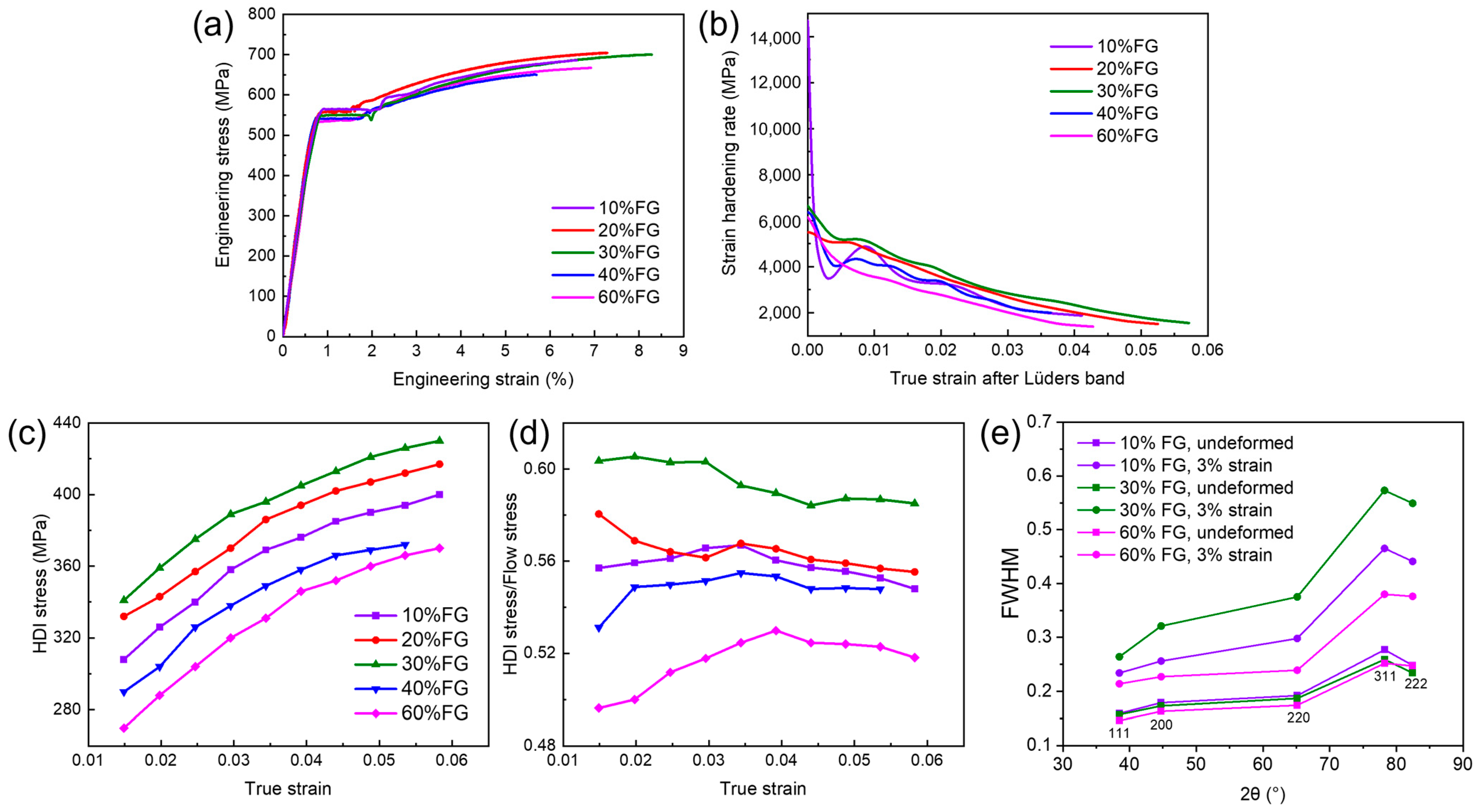
3.2. Tensile Behaviors of the Trimodal Composites

The tensile test and LUR test of the five samples are carried out to investigate the FG domains induced strain hardening. The strain rate is 5 × 10⁻⁴/s. The tensile stress–strain curves are shown in Figure 2a and the strain-hardening curves are shown in Figure 2b. The tensile properties are listed in Table 4. The yield strength lowers down a little with an increasing content of FG, which is consistent with the Hall–Petch relationship. However, the ductility does not necessarily increase with a higher content of FG. The strain-hardening capacity and ductility are improved with more FG when its content is less than 30 vol.%, but ductility loss occurs when more FG domains are introduced, e.g., 40 vol.% FG domains.
The best strength–ductility synergy is present in the 30% FG sample, which is related to its best ability of strain hardening and highest HDI stress according to Figure 2b,c. The higher HDI stress allows for a higher strain-hardening rate in the five samples. In addition, the ratio of HDI stress to flow stress in 30% FG is ~58% (Figure 2d), the highest among the five samples, indicating that the long-range back stress induced kinematic hardening takes advantage in the strain hardening. On the contrary, 60% FG exhibits the lowest HDI stress and strain hardening rate. Interestingly, the ductility of 60% FG is not the worst. Thus, HDI strain hardening is the major strain hardening mechanism but not the only factor determining the ductility. Among the other strain hardening mechanisms that contribute to the improved ductility, dislocations multiplication and their short-range interaction induced forest hardening is of critical significance. According to the Williamson–Hall method [20], the dislocation multiplication and the increase in full width at half maximum (FWHM) of the characteristic peaks in the XRD spectra have a positive correlation. Therefore, to verify whether the improved ductility in 60% FG is attributed to forest hardening, the evolution of FWHM in XRD spectra is obtained and shown in Figure 2e. The broadening of peaks after a strain of 3% is the highest in 30% FG while it is the lowest in 60% FG. Therefore, the dislocation multiplication cannot explain the improved ductility of 60% FG. Since the major difference in the trimodal grain structure is the content of FG and the presence of FG/CG hetero-zone boundaries at a high content of FG, it is deduced that the abnormal improved ductility in 60% FG is attributed to the FG/CG interface mediated strain partition and stress relaxation.

4. Discussion

The heterogeneous deformation among UFG, FG and CG domains lead to the formation of Hbar with characteristic length, which is expressed as [13]
l H b a r = b μ σ 2
where b = 0.286 nm is the Burgers vector, μ = 27 GPa is the shear moduli and σ is the yield strength of FG or CG domains. l H b a r has been seen as a simple criterion in distinguishing whether the soft domains can exert good HDI strain hardening in the hetero-structured metals [13,14]. The size of soft domains is expected to be ~2 l H b a r . However, our previous study reveals that, for hetero-structured AMCs, the optimal size of CG domains should be larger than 2 l H b a r and approximate to the size of the plastic zones ( r p ) at crack tips [9]. In this study, the size of CG domains is regulated to be r p in the five samples. In this case, the size of FG domains must be much smaller than r p . In fact, FG domains are not designed to blunt micro-cracks as CG domains but provide HDI strain hardening to evade the pre-mature cracking of UFG/CG domains. Therefore, more importantly, the relationship between the size of FG domains and its l H b a r requires understanding. For FG domains, σ can be estimated as the strength of typical Al-4 Cu-1.5 Mg alloys, at 400–500 MPa [21]. Therefore, l H b a r in FG domains is estimated to be 0.8–1.3 μm, larger than the size of FG domains. Thus, FG domains cannot independently accommodate the GNDs required for heterogeneous deformation, and the fixed 20 vol.% CG domains also work to evade early plastic instability. In trimodal composites with an FG content of less than 30%, the more FG domains added, the more hetero-zone boundaries of UFG/FG that are introduced. Thus, there is a higher volume fraction of the Hbar in FG domains present to store GNDs and alleviate the strain incompatibility at UFG/FG and UFG/CG hetero-zone boundaries. This is the reason why the 30% FG sample exhibits the best ability in dislocation multiplication (Figure 2e).
The CPFEM simulation is used to investigate the distribution of GNDs and SSDs in 10% FG, 30% FG and 60% FG, as shown in Figure 3. Figure 3a–c show the RVE of 10% FG, 30% FG and 60% FG, respectively. The green, yellow and red regions correspond to UFG, FG and CG domains, respectively. Figure 3d–i are the distribution of GNDs and SSDs of the three samples. To clear the difference in dislocation density and distribution in the three samples, a strain of 4% is selected. The SSDs densities show little difference but the GNDs densities are remarkably different from each other. The 30% FG sample shows the highest density of GNDs (~6.89 × 10¹⁴/m2), while the GNDs density in 10% FG and 60% FG is only ~3.72 × 10¹⁴/m2 and ~2.87 × 10¹⁴/m2, respectively. The HDI stress increases with a higher GNDs density, thus leading to a higher strain-hardening rate.
Even though increasing the volume fraction of FG domains is beneficial for strength–ductility synergy, there is an upper limit of addition of FG. When the volume fraction of FG domains is less than 30%, neither clusters of FG nor hetero-zone boundaries of FG/CG can be found. But, when the volume fraction of FG domains is as high as 40% or 60%, FG clusters can be observed and some FG domains tend to form a UFG/FG interface on one side and FG/CG interface on the other side. The FG/CG interface cannot contribute to the GNDs storage in FG. As a result, it fails to relax the stress concentration at the UFG/CG interface. It is noteworthy that even though stress concentration at hetero-zone boundaries is an ordeal for interfacial toughness, it promotes the formation of the Hbar and increases the HDI stress. The HDI stress in the Hbar of CG domains can be calculated by [22]
σ H D I = 2 k 2 d 1 σ s o f t σ h a r d 2 + σ s o f t 2 σ s o f t
where k is the Hall–Petch constant and d is the grain size. σ s o f t and σ h a r d are the strength of soft domains and hard domains in hetero-structured materials, respectively. If one replaces the UFG/CG interface with the FG/CG interface, σ h a r d in Equation (9) is altered from σ U F G to σ F G and the reduction in HDI stress in the Hbar of CG is inevitable. Therefore, the macroscopic HDI stress starts to decrease when some FG/CG hetero-zone boundaries are present.
Most of the UFG/CG interface is replaced by the FG/CG interface when the volume fraction of FG is as high as 60%. Since most of the UFG/CG interface disappears, the HDI stress is prone to decreasing according to Equation (9) but the accompanied vanishing of the UFG/CG interface is favorable in strain homogenization and stress relaxation [21]. Figure 4 is the simulated distribution stress and strain of 10% FG, 30% FG and 60% FG after a strain of 4%. Figure 4a–f are the distribution of the stress and strain of the three samples. The white arrows mark the points with the highest local stress or strain. These figures show that when the volume fraction of FG is 60%, not only is the stress concentration relaxed but also the strain field is more homogeneous than that of the 30% FG sample. It contributes to the low-rate but sustained strain hardening in the 60% FG sample. In addition, large FG clusters with a better dislocation storage capacity than the UFG domains [6] can form and their intrinsic toughening effect on the ductility of 60% FG sample is also significant. Nonetheless, the HDI stress is limited and the HDI strain hardening is relatively weak in the 60% FG sample. A good heterostructure design requires balancing the HDI strain hardening and the high-content soft phase induced strain homogenization.

5. Conclusions

In summary, the volume fraction of FG domains in trimodal grain structured CNT/Al-4 Cu-1.5 Mg composites is tuned elaborately. With an increasing content of FG, the strength reduces a little according to the Hall–Petch relationship, while the ductility increases first and then decreases and increases again. A combination of 50%UFG-30%FG-20%CG is most effective in obtaining strength–ductility synergy, with an optimized tensile strength of over 700 MPa and an elongation of 7.5%, respectively. When there are no clusters of FG or formation of an FG/CG interface, more FG is required to store extra GNDs and activate higher HDI strain hardening, as well as to relieve the stress concentration at the UFG/CG interface. The replacement of the UFG/CG interface by the FG/CG interface occurs when the FG content is higher than 30 vol.%, and it triggers a decrease in GNDs density and HDI stress, thus losing ductility. But, when it comes to a 60 vol.% of FG, the vanishing of the UFG/CG interface results in strain homogenization and compensation of ductility. This work demonstrates the significance in tuning the distribution of hetero-domains and provides a deeper understanding for the design of hetero-structured materials.

Author Contributions

Conceptualization: Z.T. and Z.L.; methodology, Z.T. and X.F.; software, S.W. and Z.Y.; formal analysis, Z.T., X.F., Z.G., G.F. and S.W.; investigation, X.F. and S.W.; resources, G.F. and Z.L.; writing—original draft preparation, Z.G. and X.F.; writing—review and editing, Z.Y., Z.T. and Z.G.; supervision, G.F. and Z.L.; project administration, Z.L.; funding acquisition, Z.T. All authors have read and agreed to the published version of the manuscript.

Funding

This work was supported by the National Key Research and Development Program of China (No. 2022YFB3707402), the National Natural Science Foundation of China (Nos. 52192592, 52171143, 52011530034, 52192591) and Shanghai Science & Technology Committee (No. 21JM0010100). Zhanqiu Tan also acknowledges the support from the Shanghai Aerospace Advanced Technology Joint Research Fund (No. USCAST2021-9).

Data Availability Statement

The raw data supporting the conclusions of this article will be made available by the authors on request.

Conflicts of Interest

The authors declare no conflicts of interest.

References

  1. Zhang, X.; Hu, T.; Rufner, J.F.; LaGrange, T.B.; Campbell, G.H.; Lavernia, E.J.; Schoenung, J.M.; van Benthem, K. Metal/ceramic interface structures and segregation behavior in aluminum-based composites. Acta Mater. 2015, 95, 254–263. [Google Scholar] [CrossRef]
  2. Li, L.; Peng, J.; Tang, S.; Fang, Q.; Wei, Y. Micromechanism of strength and damage trade-off in second-phase reinforced alloy by strain gradient plasticity theory. Int. J. Plast. 2024, 176, 103970. [Google Scholar] [CrossRef]
  3. Schwarze, C.; Kamachali, R.D.; Steinbach, I. Phase-field study of zener drag and pinning of cylindrical particles in polycrystalline materials. Acta Mater. 2016, 106, 59–65. [Google Scholar] [CrossRef]
  4. Zhang, D. Ultrafine grained metals and metal matrix nanocomposites fabricated by powder processing and thermomechanical powder consolidation. Prog. Mater. Sci. 2021, 119, 100796. [Google Scholar] [CrossRef]
  5. Zhang, J.; Pang, X.; Li, Y.; Wei, S.; Yang, C.; Pan, S.; Sun, B.; Zhou, D.; Huang, X.; Zhang, D.; et al. Tuning generalized planar fault energies to enable deformation twinning in nanocrystalline aluminum alloys. Int. J. Plast. 2024, 178, 104018. [Google Scholar] [CrossRef]
  6. Galindo-Nava, E.I.; Sietsma, J.; Rivera-Díaz-del-Castillo, P.E.J. Dislocation annihilation in plastic deformation: II. Kocks–Mecking Analysis. Acta Mater. 2012, 60, 2615–2624. [Google Scholar] [CrossRef]
  7. Zhao, L.; Zheng, W.; Hu, Y.; Guo, Q.; Zhang, D. Heterostructured metal matrix composites for structural applications: A review. J. Mater. Sci. 2024, 59, 9768–9801. [Google Scholar] [CrossRef]
  8. Zhu, Y.; Wu, X. Heterostructured materials. Prog. Mater. Sci. 2023, 131, 101019. [Google Scholar] [CrossRef]
  9. Tan, Z.; Fu, X.; Zheng, Q.; Lin, R.; Chen, M.; Fan, G.; Xiong, D.-B.; Li, Z. Toward strength-ductility synergy in trimodal grain structured metal composites by actively tuning coarse domains. Mater. Res. Lett. 2023, 11, 462–470. [Google Scholar] [CrossRef]
  10. Liu, Z.Y.; Ma, K.; Fan, G.H.; Zhao, K.; Zhang, J.F.; Xiao, B.L.; Ma, Z.Y. Enhancement of the strength-ductility relationship for carbon nanotube/Al–Cu–Mg nanocomposites by material parameter optimisation. Carbon 2020, 157, 602–613. [Google Scholar] [CrossRef]
  11. Liu, J.; Liu, C.; Cai, H.; Zhang, C.; Dan, C.; Shi, Q.; Wang, H.; Chen, Z. Enhanced precipitate strengthening in particulates reinforced Al–Zn–Mg–Cu composites via bimodal structure design and optimum aging strategy. Compos. Part B Eng. 2023, 260, 110772. [Google Scholar] [CrossRef]
  12. Wang, Y.; Zhu, Y.; Yu, Z.; Zhao, J.; Wei, Y. Hetero-zone boundary affected region: A primary microstructural factor controlling extra work hardening in heterostructure. Acta Mater. 2022, 241, 118395. [Google Scholar] [CrossRef]
  13. Huang, C.X.; Wang, Y.F.; Ma, X.L.; Yin, S.; Höppel, H.W.; Göken, M.; Wu, X.L.; Gao, H.J.; Zhu, Y.T. Interface affected zone for optimal strength and ductility in heterogeneous laminate. Mater. Today 2018, 21, 713–719. [Google Scholar] [CrossRef]
  14. Wu, H.; Huang, M.; Xia, Y.; Li, X.; Li, R.; Liu, C.; Gan, W.; Xiao, T.; Geng, L.; Liu, Q.; et al. The importance of interfacial stress-affected zone in evading the strength-ductility trade-off of heterogeneous multi-layered composites. Int. J. Plast. 2023, 160, 103485. [Google Scholar] [CrossRef]
  15. Zan, Y.N.; Zhou, Y.T.; Liu, Z.Y.; Ma, G.N.; Wang, D.; Wang, Q.Z.; Wang, W.G.; Xiao, B.L.; Ma, Z.Y. Enhancing strength and ductility synergy through heterogeneous structure design in nanoscale Al2O3 particulate reinforced Al composites. Mater. Des. 2019, 166, 107629. [Google Scholar] [CrossRef]
  16. Wan, J.; Chen, B.; Zhou, X.; Cao, L.; Geng, H.; Shen, J.; Bahador, A.; Kondoh, K.; Li, J. CNT-induced heterogeneous matrix grain structure in CNTs/Al composites. Carbon 2024, 216, 118529. [Google Scholar] [CrossRef]
  17. Ma, K.; Liu, Z.Y.; Liu, K.; Chen, X.G.; Xiao, B.L.; Ma, Z.Y. Structure optimization for improving the strength and ductility of heterogeneous carbon nanotube/Al–Cu–Mg composites. Carbon 2021, 178, 190–201. [Google Scholar] [CrossRef]
  18. Fu, X.; Tan, Z.; Ma, Z.; Li, Z.; Fan, G.; Xiong, D.-B.; Li, Z. Powder assembly & alloying to CNT/Al–Cu–Mg composites with trimodal grain structure and strength-ductility synergy. Compos. Part B Eng. 2021, 225, 109271. [Google Scholar] [CrossRef]
  19. Zhao, J.; Lu, X.; Yuan, F.P.; Kan, Q.; Qu, S.; Kang, G.; Zhang, X. Multiple mechanism based constitutive modeling of gradient nanograined. Mater. Int. J. Plast. 2019, 125, 314–330. [Google Scholar] [CrossRef]
  20. Ungár, T.; Dragomir, I.; Révész, Á.; Borbély, A. The contrast factors of dislocations in cubic crystals: The dislocation model of strain anisotropy in practice. J. Appl. Crystallogr. 1999, 32, 992–1002. [Google Scholar] [CrossRef]
  21. Teng, H.; Tan, Z.; Zhao, X.; Fan, G.; Yue, Z.; Li, Z.; Xiong, D.-B. Simultaneously enhanced strength and ductility in graphene nanosheet/Al-Cu-Mg nano-laminated composites by incorporating coarse domains. Mater. Res. Lett. 2023, 11, 143–151. [Google Scholar] [CrossRef]
  22. Chou, T.H.; Li, W.P.; Chang, H.W.; Du, X.H.; Chuang, W.S.; Yang, T.; Zhu, Y.T.; Huang, J.C. Quantitative analysis of hetero-deformation induced strengthening in heterogeneous grain structure. Int. J. Plast. 2022, 159, 103482. [Google Scholar] [CrossRef]
Figure 1. Trimodal grain structure of 10% FG, 20% FG, 30% FG, 40% FG and 60% FG. (ae) Trimodal grains morphology characterized by EBSD. (fj) Corresponding statistical results of grain size distribution.
Metals 14 00891 g001
Figure 2. Tensile behaviors of trimodal composites with different content of FG. (a) Engineering stress–strain curves. (b) Strain-hardening curves. (c) HDI stress evolution during plastic deformation. (d) The ratio of HDI stress to flow stress during plastic deformation. (e) The increase in FWHM of 10% FG, 30% FG and 60% FG after strain of 3%.
Metals 14 00891 g002
Figure 3. Distribution of GNDs and SSDs after strain of 4%. (ac) RVE of 10% FG, 30% FG and 60% FG. (df) Distribution of GNDs in 10% FG, 30% FG and 60% FG. (gi) Distribution of SSDs in 10% FG, 30% FG and 60% FG.
Metals 14 00891 g003
Figure 4. Distribution of stress and strain after strain of 4%. (ac) Distribution of stress in 10% FG, 30% FG and 60% FG. (df) Distribution of strain in 10% FG, 30% FG and 60% FG.
Metals 14 00891 g004
Table 1. The purity, granulometry and supplier of the powders.
PowderPurityAverage SizeSupplier
Pure Al>99.8%33 μmHenan Yuanyang Powder Technology Co., Ltd. (Henan, China)
Pure Mg>98.5%29 μm
Flaked pure Cu>98.8%diameter ~6.4 μm
thickness ~0.1 μm
Pure 2024 Al>99.5%33 μm
CNTs——diameter 30–50 nm
length ~5 μm
Chengdu Organic Chemistry Co., Ltd. (Chengdu, China)
Table 2. The composition of the matrix of the composites (wt.%).
CuMgMnZnAl
4.031.540.770.22Bal.
Table 3. Statistical result of grain size.
SampleUFGFGCG
10% FG218 ± 51 nm729 ± 102 nm4.9 ± 0.7 μm
20% FG201 ± 66 nm747 ± 93 nm4.4 ± 0.8 μm
30% FG203 ± 46 nm732 ± 88 nm4.6 ± 0.8 μm
40% FG193 ± 54 nm789 ± 112 nm5.1 ± 0.7 μm
60% FG187 ± 62 nm793 ± 104 nm4.8 ± 0.9 μm
Table 4. Tensile properties of the trimodal grain structured composites.
SampleYield strength (MPa)Ultimate strength (MPa)Elongation (%)
10% FG560 ± 3693 ± 35.7 ± 0.2
20% FG556 ± 2705 ± 36.4 ± 0.3
30% FG548 ± 3701 ± 47.5 ± 0.2
40% FG540 ± 5655 ± 54.9 ± 0.4
60% FG532 ± 4667 ± 36.1 ± 0.2
Disclaimer/Publisher’s Note: The statements, opinions and data contained in all publications are solely those of the individual author(s) and contributor(s) and not of MDPI and/or the editor(s). MDPI and/or the editor(s) disclaim responsibility for any injury to people or property resulting from any ideas, methods, instructions or products referred to in the content.

