Abstract
The presented paper characterized the molten salt-modified Ni electrode with excellent catalytic activity towards alkaline urea electrooxidation reaction. The electrodes were modified by electrodeposition of Al from molten salt electrolytes containing NaCl-KCl-AlF3 at a temperature of 750 °C and applied potential of −1.9 V. The porous surface was obtained by anodic polarization with a potential of −0.4 V until the anodic current was equal to 0 mAcm−2. The prepared deposits’ structure, surface morphology, and composition were analyzed using scanning electron microscopy (SEM) and X-ray diffraction (XRD). Anodic polarization was applied to assess the electrocatalytic activity and elucidate the urea electrooxidation mechanism in 1 M KOH + 0.33 M urea solution. The nanocrystalline structure, fine grain size, and microcracks on the surface of the studied electrodes contributed to their notably high electrochemically active surface area (ECSA). The cyclic voltammetry in the non-Faradaic regions of the samples shows that molten salt modification can increase the double layer capacitance of bare Ni plates by around ten times, from 0.29 mFcm−2 to 2.16 mFcm−2. Polarization of the electrodes in urea-containing KOH solution with potential of +1.52 V shows a significant difference in catalytic performance. For the bare nickel sample, the registered current density from the urea electrooxidation reaction was around +1 mAcm−2, and for the molten salt-modified one, it was +38 mAcm−2, which indicates the fact that the molten salt surface treatment can be a promising tool in tailoring the electrochemical properties of materials.
1. Introduction
Significant attention is currently focused on water splitting, which has become an economically sufficient way to decrease the prices of hydrogen production. Theoretically, the voltage needed for splitting water in alkaline electrolysis is approximately 1.23 V (at 298 K). However, in practice, electrolyzers experience higher actual voltages, around 1.8 V or more, due to ohmic losses and the polarization of electrode reactions, with particular attention to the anodic oxygen evolution reaction [1].
A way to significantly decrease energy demand is by reducing the thermodynamically needed voltage and replacing the anodic-oxygen evolution reaction with an alternative process requiring a lower overpotential value. In this regard, urea oxidation reaction (UOR) is considered an effective and promising substitute [2].
According to Protsenko’s thermodynamic calculation related to open-circuit voltages for electrolytic urea oxidation, the frequently cited value of 0.37 V in the existing literature is likely incorrect. A more accurate figure was determined to be 0.072 V at the same standard temperature [3,4]. Modifying the anodic reaction creates new challenges regarding electrode materials synthesis, which must be active in UOR, exhibit high catalytic activity, and have sufficient resistance in strong anodic polarization in alkaline solutions [5].
Based on the previously conducted studies related to the electrooxidation of organic compounds like alcohols and urea, the materials dedicated to these reactions must be able to form an oxide/hydroxide layer on their surface, which is a necessary point in terms of organic molecule oxidation. Broggs and Daramola proposed a mechanism of urea electrooxidation on nickel electrodes, which involved the formation of an active NiOOH layer on the surface [6]. During contact with urea, this compound is chemically reduced to inert Ni(OH)2 and covered by oxidation products like N2 and CO2. Significant anodic polarization of the electrode leads to the regeneration of NiOOH species on the electrode surface, and according to this mechanism, the limiting step of this process is the transport of gaseous reaction products from the electrode surface, especially CO2 gas, the presence of which was confirmed by Raman spectroscopy measurements.
The ability to form the OOH/OH redox couple is why nickel electrodes can be utilized as efficient electrode materials in urea electrooxidation [7]. The authors proposed the potential urea electrooxidation mechanism as follows:
Ni(OH)2(s) + OH− = NiOOH(s) + H2O(l) + e−
NiOOH(s) + urea(l) = Ni(OH)2(s) + products
Modifying the activity and selectivity in anodic reactions has also been studied extensively in recent years. In scientific literature, it is possible to find many articles related to compositional studies on Ni-Co, Ni-Fe, Ni-Mo, Ni-Pt, NiOx-CuOx, and other Ni-based alloys, which can be effectively used for urea electrooxidation [8,9,10,11,12]. This is one of the ways to enhance activity and durability.
Another approach for obtaining highly active electrodes involves playing with the morphology and electrochemically active surface area. Mao Sung Wu, in his work, prepared vertically aligned mesoporous nickel oxide nanosheets on the surface of commercially available porous Ni foam. The authors used a typical hydrothermal synthesis, which allowed them to form a well-developed nickel structure that exhibited excellent catalytic performance in urea electrooxidation [13]. Madhav et al. successfully synthesized 2D NiO hexagonal nanodiscs with thicknesses between 4 and 20 nm. Fabricating a well-developed surface with many sharp edges and an extraordinary density of electrochemically active centers can provide excellent catalytic properties [14]. Another idea related to the electrophoretic deposition of NiO nanoparticles was obtained by a conventional precipitation method using a microwave oven, as performed by Navarro-Aguilar et al. Small-sized nanoparticles of NiO (size between 2 and 3 nm) were electrophoretically deposited on Al plates and used as working electrodes in urea electrooxidation reaction [15].
A way to significantly increase the surface area is to form Ni-based alloys, like Zn-Al and Ni-Al, which can later be selectively dissolved and reveal the porous structure [16]. This technique was used for Ni-Raney synthesis, one of organic chemistry’s most critical Ni-based catalysts [17]. Usually, Ni-Al alloys are prepared by mixing the fine powders of two elements, which are later heated and pressed to form a solid electrode. The prepared material is then immersed in a strong alkaline solution, which allows for the dissolution of Al from the alloy and the revelation of the porous body [18]. The scientific literature suggests that intermetallic phases between Al3Ni can be formed even below the melting point of aluminum, like 450 °C, but the penetration into the depth of the nickel substrate is not greater than 10 µm, even after 8 h of heat treatment [19].
In our study, we employed a new idea for the surface development of nickel electrodes, including high-temperature molten salt treatment. The method of fabrication of the thick, porous nickel electrode by subsequent deposition/dissolution of Al from molten salts was used in our previous works regarding bulk nickel and its alloys with cobalt and platinum [20,21]. Deposition of aluminum in molten salts on the nickel surface is performed at a temperature of 950 °C, slightly above the melting point of pure aluminum. Under these conditions, the Al-Ni phases’ formation mechanism and growth kinetics are fast. The formation of Al-Ni intermetallic phases can be broken down into two key steps: lateral and perpendicular growth. Initially, intermetallic phases emerge from separate sites and grow laterally. This process forms a continuous layer of intermetallic compound on the substrate. Once a continuous layer has formed, the growth continues in a direction perpendicular to the interface between the Ni coating and the Al substrate. This perpendicular growth enhances the thickness of the intermetallic layer. The deposition/dissolution process, performed under optimized conditions, creates a thick and well-distributed porous structure which can be used as a highly active electrode for hydrogen/oxygen evolution reactions, as confirmed in our previous works [22,23].
This study aims to synthesize a porous nickel electrode by means of deposition/dissolution of Al on the Ni substrate and to investigate its electrocatalytic performance in the urea electrooxidation reaction in alkaline solutions. The results obtained for the porous Ni electrodes were compared with bare nickel substrates as the reference.
2. Experimental Details
2.1. Sample Preparation
A nickel (Ni) plate with a thickness of 0.5 cm and electric conductivity of 1.4 × 10⁷ Sm−1 was used as a substrate to form a porous coating. The sample surface was polished with 800-grit sandpaper, followed by ultrasonic cleaning in acetone. This prepared sample, with a surface area of approximately 2.42 cm−2, was used consistently in each experiment.
2.2. Molten Salts Treatment
The aluminide layer was produced by electrolytic deposition of aluminum (Al) using molten salt as a medium. The electrolytic bath consisted of a NaCl-KCl mixed salt with an equimolar composition, supplemented with 3.5 mol% AlF3. After Al electrodeposition, only the aluminum component was dissolved to create a porous surface. The electrolytic cells used in these experiments have been described in previous publications [24]. A mixed salt of NaCl-KCl-AgCl (45:45:10 mol%) in a mullite tube with an outer diameter of 6 mm and a length of 500 mm served as the reference electrode. An Ag wire immersed in the mixed salt acted as the reference electrode. The bath temperatures for Al electrodeposition and dissolution were 900 °C, respectively. Al electrodeposition was carried out at constant potentials of −1.9 V, followed by Al dissolution at −0.5 V. After treatment, the sample was removed from the bath, and any adhering salt was removed by washing it with water.
2.3. Instrumental Analysis
The surfaces of the treated and non-treated samples were examined and analyzed using a scanning electron microscope (SEM) (JEOL, Tokyo, Japan) equipped with an energy-dispersive X-ray spectrometer (EDS). X-ray diffraction (XRD) measurements were performed using a Rigaku MiniFlex II apparatus (Rigaku, Tokyo, Japan) with a Cu lamp.
2.4. Electrochemical Activity Evaluation
In order to assess the electrochemical behavior after molten salt treatment, anodic polarization scans were performed in a 1 M NaOH solution (pH = 14.00). All potential values in the presented research have been recalculated to a reversible hydrogen electrode (RHE) according to Equation (3):
where: ERHE is the converted potential vs. RHE, EHg/Hg2Cl2 is the experimentally measured potential versus the Hg/Hg2Cl2 reference electrode, and EoHg/Hg2Cl2 is the standard potential of Hg/Hg2Cl2 at 25 °C (0.245 V).
ERHE = EHg/Hg2Cl2 + 0.059 pH + Eo Hg/Hg2Cl2
In addition, electrochemical surface area (ECSA) measurements in the non-faradaic potential range (±0.05 V vs. OCP) were performed to compare surface evolution. Furthermore, both porous and unmodified Ni samples were subjected to potentiostatic polarization measurements in 1 M NaOH and 1 M NaOH + 0.33 M urea electrolytes (pH = 14.10) with an applied potential of +1.53 V for 3600 s. The potential value was selected according to the maximum oxidation peak registered during the linear voltammetry tests of porous and unmodified Ni electrodes in solutions with and without urea addition. Chronoamperometric tests with urea-consisting electrolytes confirmed a significant increase in the electrochemical activity of the molten salt-treated electrode during the urea electrooxidation reaction.
3. Results and Discussion
3.1. Molten Salt Treatment of Ni Electrode
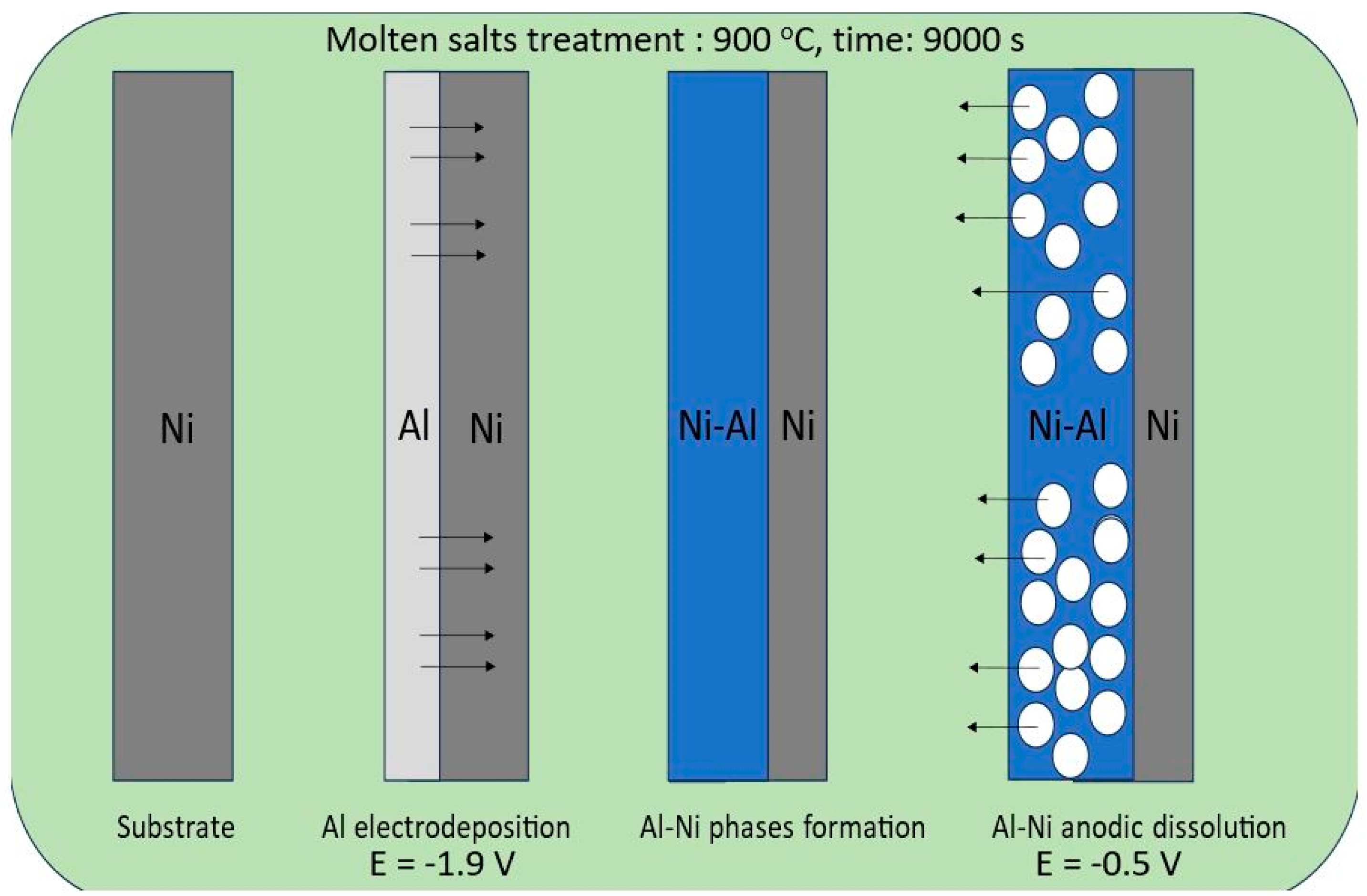
In this study, we applied a molten salt treatment on a nickel plate to fabricate porous Ni electrodes. The surface development level of the obtained porous structures was strongly connected with selected deposition/dissolution potentials and the temperature of the molten salt electrolyte during the formation of alloys. The mechanism of the formation of porous structures was related to the reaction between electrodeposited aluminum and the substrate material. A schematic plot of the molten salt treatment, along with the deposition/dissolution process, is presented in Figure 1.

Figure 1.
Graphical representation of nickel electrode molten salt treatment via the deposition/dissolution process of Al.
On the Ni surface, the electrodeposited Al layer under the applied temperature was in the liquid state, which significantly increased the reaction rate between these two elements due to the high mobility and penetration of Al into the bulk Ni plate. In the case of the currently studied system, the porous structure formation resulted from the solid-state reaction between nickel and deposited Al, which can form an Al-Ni phase at high temperatures. The obtained intermetallic solid can be easily dissolved by applying the anodic potential presented in Figure 2.
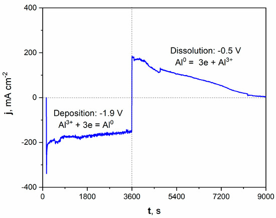
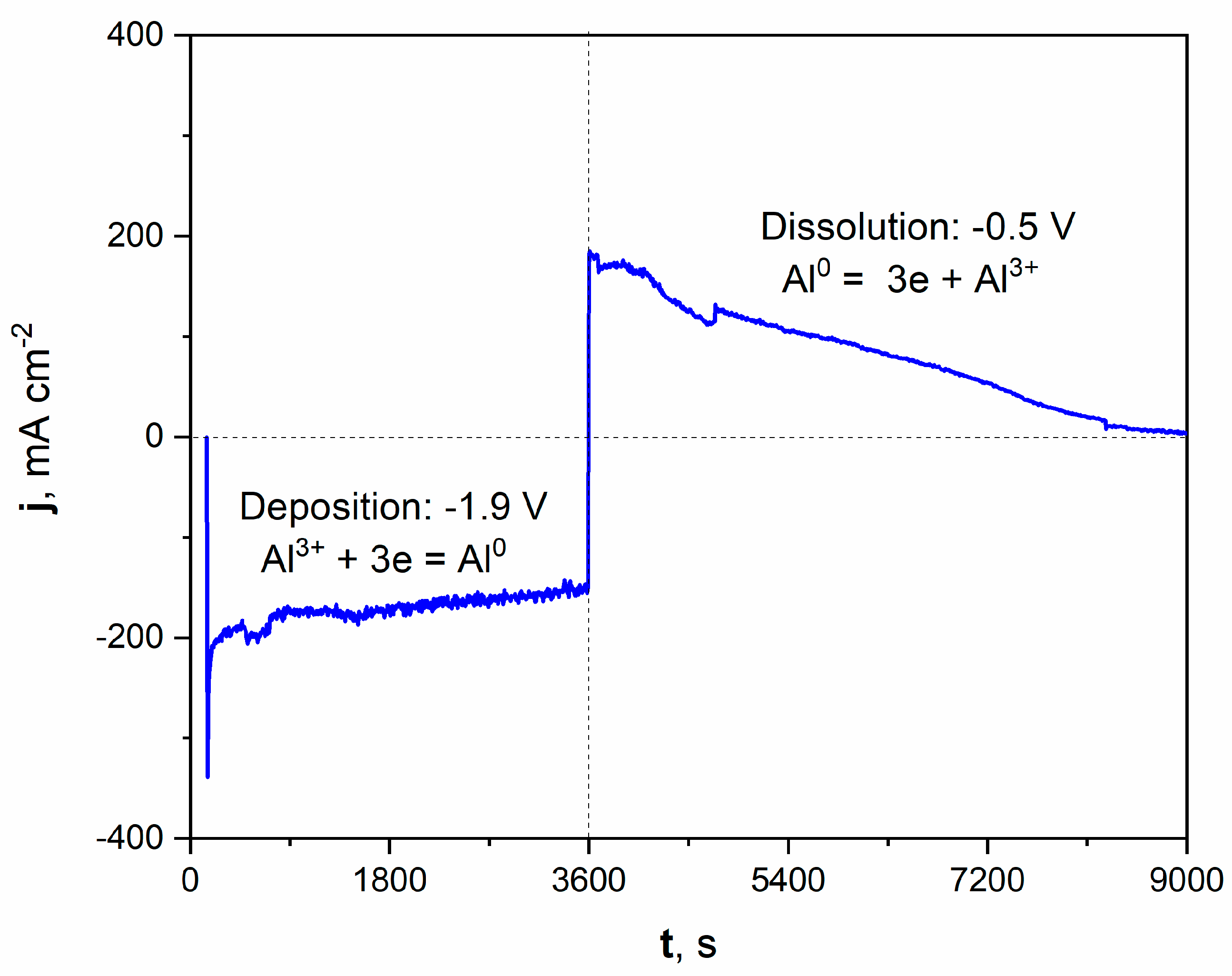
Figure 2.
Current vs. time plot of deposition/dissolution of Al during molten salt treatment of Ni electrode. Deposition time: 3600 s, applied potential: −1.9 V. Dissolution time: 5400 s, applied potential: −0.5 V. Temperature of molten salt treatment: 900 °C.
The registered current density during the potentiostatic porous layer formation is graphically presented on the left part of the plot. Applying a potential of −1.9 V increased the cathodic current density, oscillating around a value close to −200 mAcm−2 during deposition. The deposition of Al from molten salts can be expressed by Equation (4):
Al3+ + 3e = Al0
After the deposition process, the potential was shifted to +0.5 V, which modified the registered current density to anodic values. This positive polarization led to the dissolution of the freshly deposited Al and, subsequently, the Al-Ni phase. The current density significantly grew to around +200 mAcm−2 at the beginning of the dissolution process. It should be noted that the registered current density gradually diminished over time. After 1.5 h of dissolution, the registered current was close to zero, which indicated the end of the Al-Ni phase dissolution and the reaching of the Ni substrate. The microscopic observation with optical and scanning electron microscope confirmed the formation of the porous structure.
3.2. Instrumental Characterization of Porous Electrodes
The scanning electron microscope images for the flat Ni plate and porous Ni electrode after molten salt treatment are presented in Figure 3.
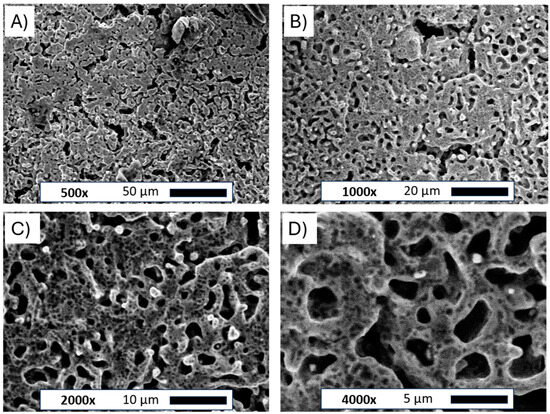
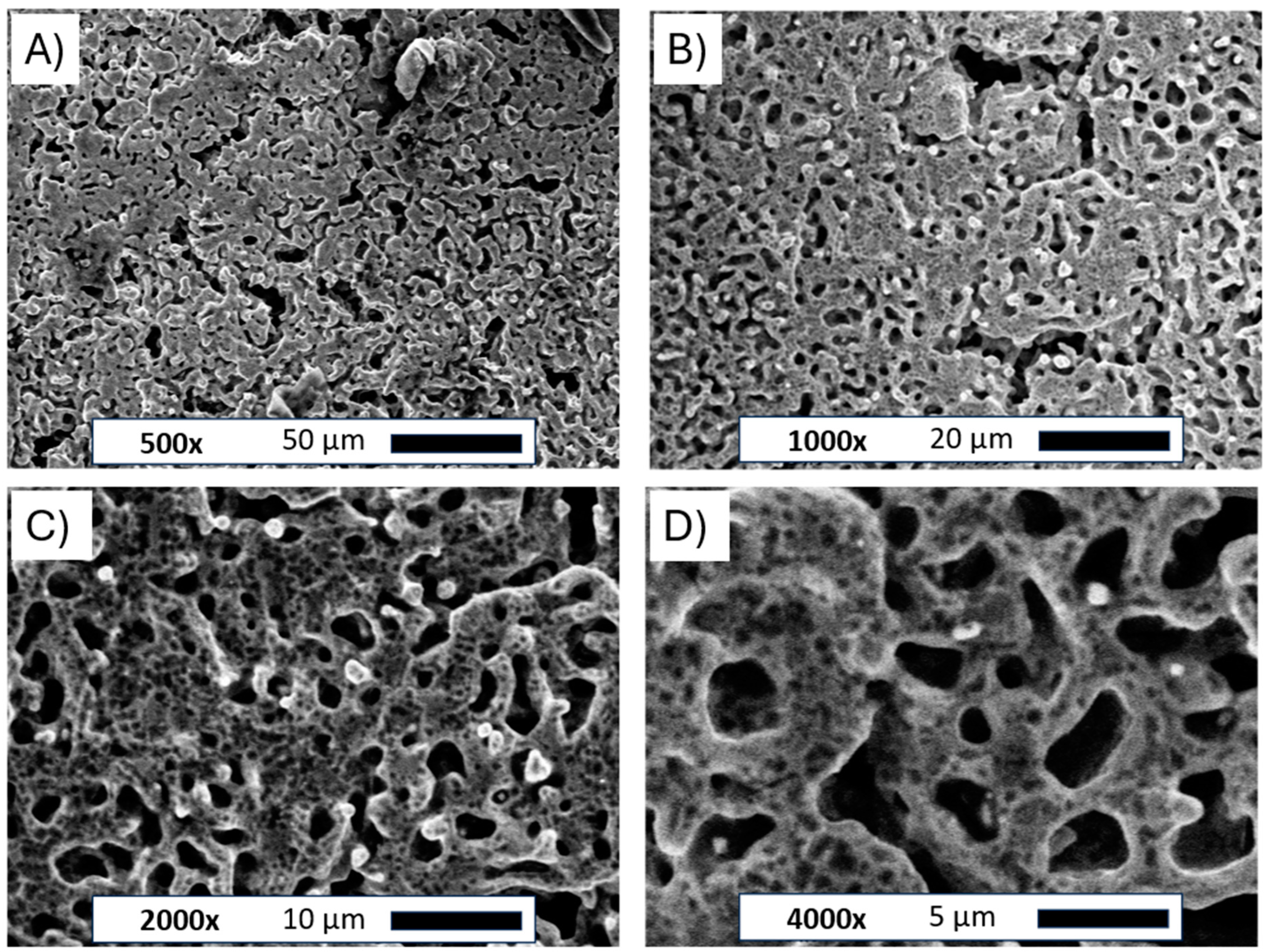
Figure 3.
SEM images of the Ni porous electrode obtained by molten salt deposition/dissolution of Al. Figure captions and magnifications: (A)—500×, (B)—1000×, (C)—2000×, (D)—4000×.
The pictures clearly show the changes in the structure of the nickel plate. The smooth bulk metallic surface was modified to form an irregular porous foam. The average size of formed holes ranged between 5 and 10 µm. The observed porous body was also covered by many smaller voids evenly distributed across the metallic foam. Such small defects on the electrode surface can be attributed to the Kirkendall effect between metallic Ni and molten Al deposited on the electrode surface, which forms intermetallic phases under such high temperatures [25]. Similar structures were observed in previously published works for Ni-Co and Ni-Pt alloys [20,21]. The unmodified and porous Ni electrode was subjected to X-ray diffraction examination, as shown in Figure 4.
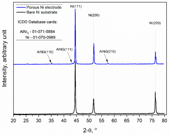
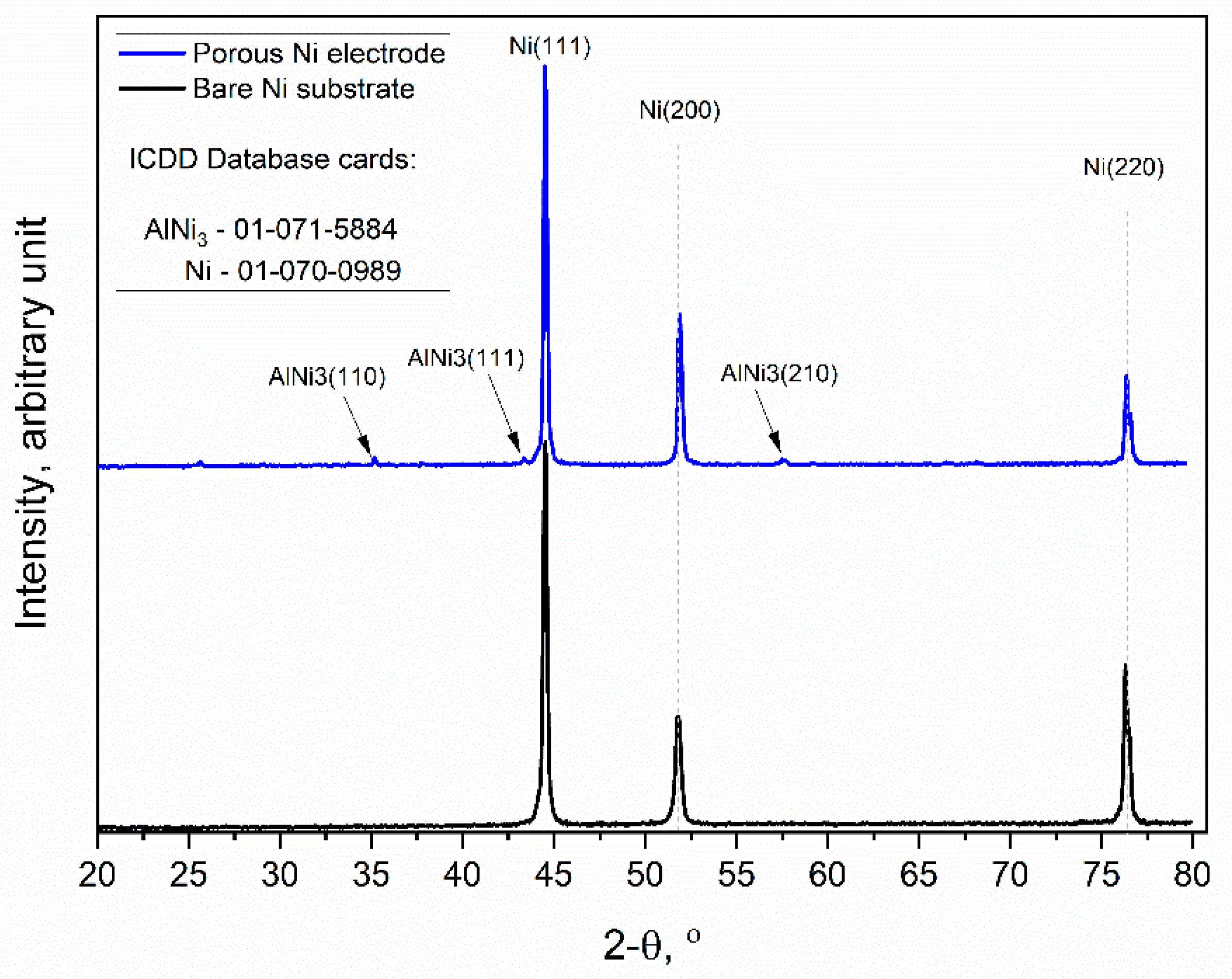
Figure 4.
X-ray diffraction patterns of the unmodified Ni and Ni porous electrode obtained by molten salt deposition/dissolution of Al. Scan speed: 0.25 deg/min.
The obtained diffraction patterns showed that the unmodified Ni sample (black line) exhibited high peak intensities for three crystallographic orientations of metallic Ni, which were (111), (200), and (220), respectively (ICDD database cards: 01-070-0989). Similarly, the molten salt-modified Ni sample (blue line) showed the same three peaks as metallic Ni, but additionally, the formation of further peaks at 35.02, 43.33, and 57.49 was observed, and this can be identified as the AlNi3 phase with orientations of (110), (111), and (210), respectively, which were not completely dissolved during the anodic polarization experiment.
3.3. Evaluation of Catalytic Activity of Molten Salts Modified Ni Electrodes
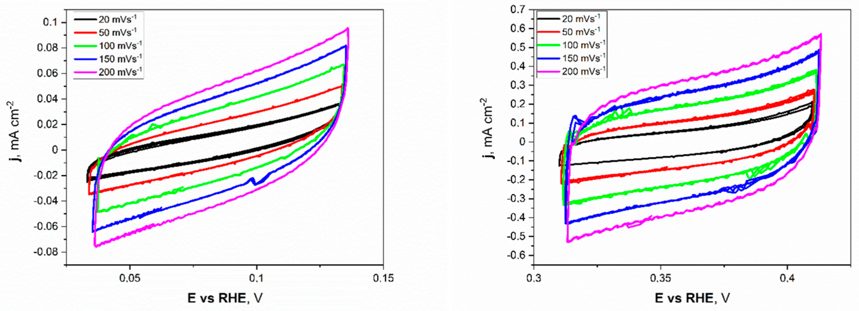
Electrochemical investigations of the Ni unmodified and porous electrodes began with the electrochemical double-layer capacitance (Cdl). Estimating the electrochemically active surface area (ECSA) is a more appropriate metric for assessing effective catalytic evaluation. As mentioned before, the measurements were conducted for a narrow electrochemical window, 0.05 V vs. OCP value, at different applied sweep rates. As presented in Figure 5, the non-faradaic region for porous Ni electrodes in 1 M NaOH was slightly shifted to more positive potentials (range from +0.32 to +0.42 V) compared to the unmodified Ni plate.

Figure 5.
The cyclic voltammetry scans with different sweep rates registered for the unmodified Ni (left) and Ni porous (right) electrodes in 1 M NaOH electrolyte.
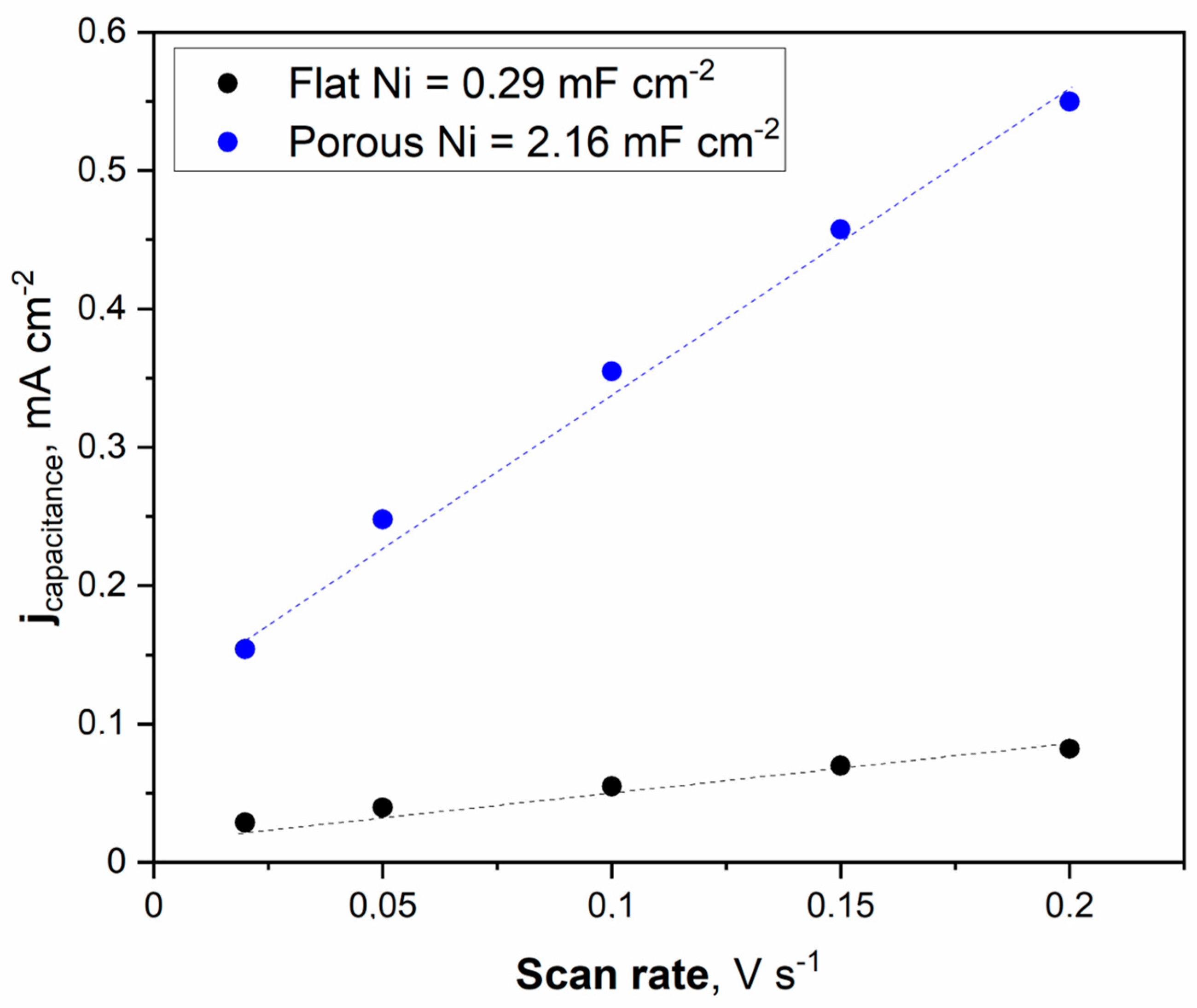
This difference can be attributed to forming a thin layer of oxides on the surface of the porous sample, especially in the 1 M NaOH electrolyte, which was chosen as a testing medium. The cyclic voltammetry (CV) scans showed a significant difference in registered current densities between flat and porous Ni samples. The figures clearly show that the porous Ni electrode exhibited higher current density. The cathodic and anodic maximum values of current densities were plotted as a function of the sweep rate, as presented in Figure 6.
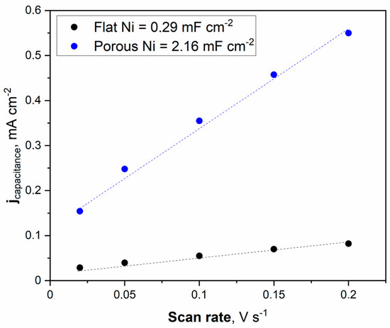
Figure 6.
The cyclic voltammetry scans with different sweep rates were registered for the unmodified Ni and Ni porous electrode in 1 M NaOH electrolyte.
The double electric layer capacitance curve illustrated in Figure 6 was obtained by fitting the data. The maximum value of the double electric layer capacitance was measured at 2.16 mFcm−2 for porous Ni, significantly higher than that of the unmodified Ni electrode (0.29 mFcm−2). This indicates that a porous Ni sample exposes more efficient catalytic active sites than a bare Ni electrode. It should be noted that the double later capacitance for porous Ni electrodes is related to the treatment conditions. In other work, the applied temperature for porous structure modification was set to 900 °C, and the obtained double layer capacitance for the Ni electrode was significantly smaller: 1.09 mFcm−2.
On the contrary, the addition of a highly active element such as Pt significantly increased the double later capacitance. In our investigations of the Ni-Pt system, the measured double-layer capacitance was much more significant and reached 28.72 mFcm−2 [21]. Determination of the ECSA value provides insights into the real electrochemically active surface area of the examined electrodes. The calculation can be performed by dividing the registered double-layer capacitance by the capacitance of the ideally flat monoatomic layer, the values of which are determined and listed in other publications [26,27,28,29].
Generally, the most common value for ECSA determination in 1 M NaOH solution is a capacitance of 40 mFcm−2. The obtained ECSA values for flat Ni and porous Ni were 7.25 cm−2 and 54 cm−2, respectively. These results show that the catalytic activity for modified Ni can be associated with a higher number of defects and other areas on the electrode, characterized by lower overpotential in electrochemical measurements than in the case of unmodified porous Ni. To confirm these findings, linear voltammetry scans (LSV) in 1 M NaOH electrolyte with and without the addition of 0.33 M urea were performed and plotted in Figure 7.
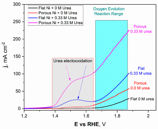
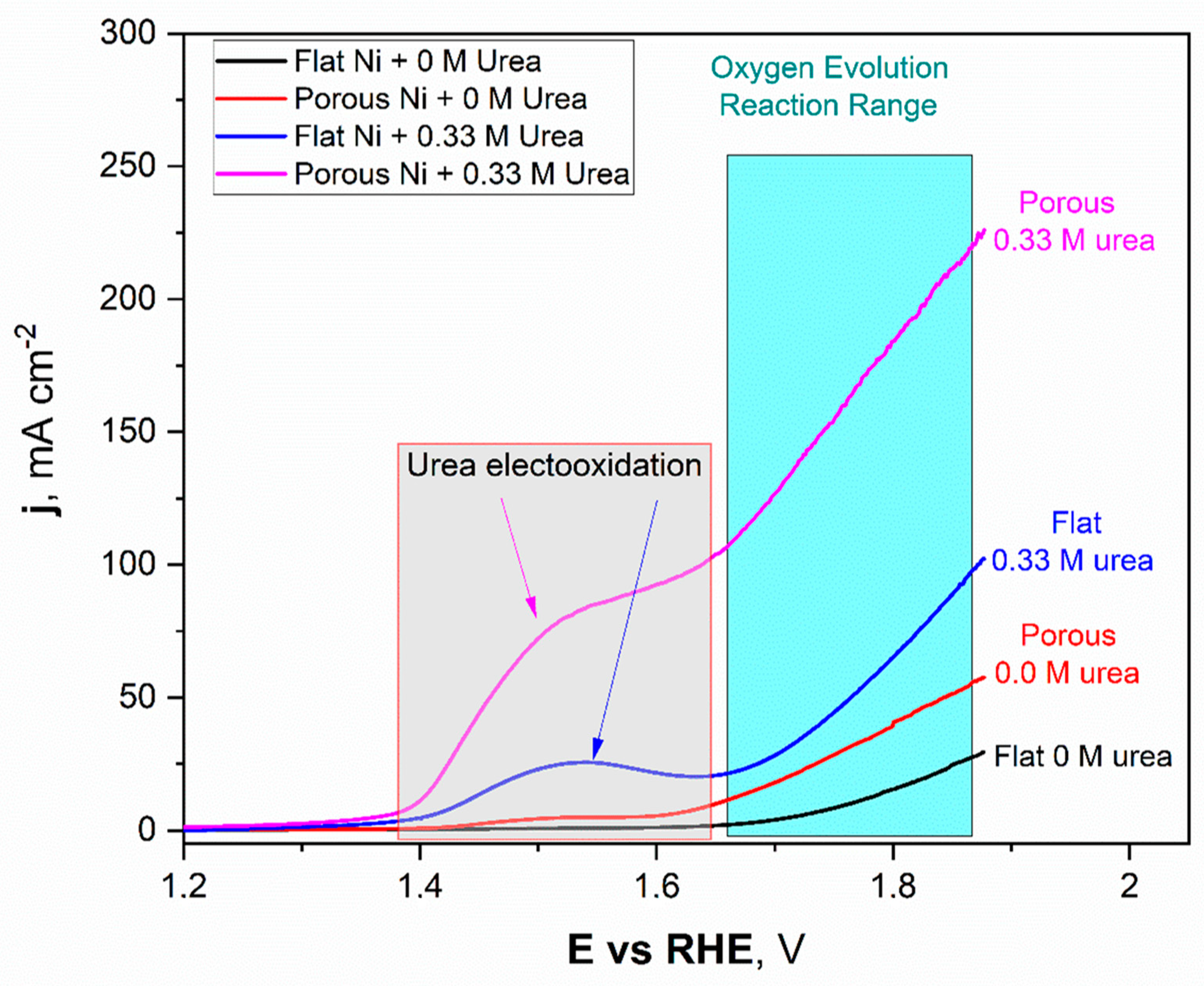
Figure 7.
The linear voltammetry scans registered for the unmodified Ni and Ni porous electrode in 1 M NaOH with and without the 0.33 M urea in electrolyte.
The obtained LSV scans for Ni unmodified (black) and porous Ni (red) electrodes with 1 M NaOH electrolyte without addition of 0.33 M urea were quite different. In the potential range between +1.42 V to +1.58 V, formation of the oxide layer on the Ni porous surface was registered and can be expressed as formation of the redox Ni(OH)2/NiOOH couple. This reaction was observed on the LSV scan as a flat current increase, which reached its maximum value close to 5 mAcm−2. In the case of the unmodified Ni sample, this signal was not registered. It should be noted that, reaching more positive potentials during the scan, the oxygen evolution reaction (OER) started at +1.59 V for porous Ni and slightly further +1.62 V for the unmodified sample. The significant difference in catalytic activity in the OER reaction can be observed in the difference in registered current densities, +29.3 mAcm−2 for unmodified sample and more than two times higher (+57.7 mAcm−2) for the porous Ni sample.
In terms of the urea-consisting electrolytes, LSV scans reveal the presence of new peaks. The urea electrooxidation reaction starts at +1.33 V, and there is a slight increase in the current density to a value of +1.39 V, which, after this potential value, grew significantly to reach a maximum value around +1.53 V. In the case of the unmodified electrode, the registered peak maximum was close to +27 mAcm−2 and was well-separated from the signals connected with the oxygen evolution reaction (from +1.62 V and above).
The porous Ni electrode, with significantly more developed surface area, was able to reach a current density of +95.3 mAcm−2 at the maximum at a potential of 1.62 V, where the oxygen evolution reaction was not present yet. Moreover, for the porous Ni electrode, the registered current density did not form the shape of a peak, as can be seen for the unmodified sample. In the potential range of 1.53–1.61 V, the visible change slope of the curve could be registered, and diffusional transport of the reaction products occurred around the interface region. The comparative analysis of the obtained results shows that the porous Ni electrodes exhibited at least three times higher current density values, corresponding to the urea electrooxidation reaction, than non-modified samples. The stability of the tested electrodes was assessed in chronoamperometric tests with an applied potential of +1.52 V, which was selected according to the LSV measurements.
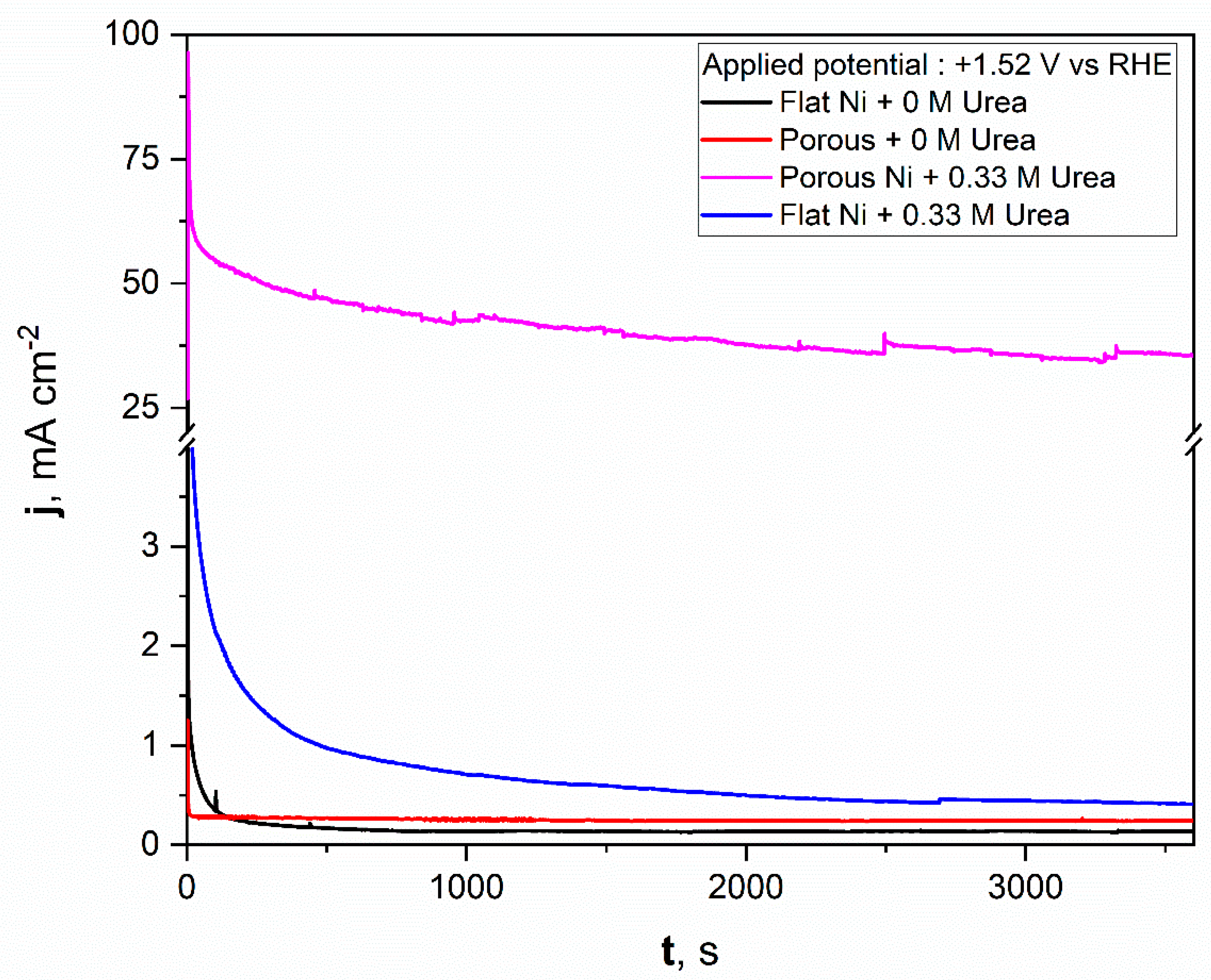
For comparison, a similar test was repeated for flat nickel with and without the urea addition in electrolyte, and the data obtained were added to the same figure. As can be seen from Figure 8, the porous nickel electrode had superior activity. During the initial time for the flat nickel electrode in the presence of urea, the current density dropped sharply, then remained almost constant around 1 mAcm−2. A significantly higher catalytic response was reposted for the porous Ni electrode. After the initial 600 s, the current density reached almost constant values around 50 mAcm−2, which indicates high electrochemical stability and high resistance against poisoning by the formed electrooxidation products. After a longer experiment time, the stable value was achieved and oscillated around 38 mAcm−2. The current fluctuations during the electrooxidation process may be related to the transport of reactants and gaseous products into and out from the nanoporous structure of nickel foam. In contrast, the flat and porous electrodes polarized with selected potential in electrolyte without urea did not exhibit any electrochemical activity, and the registered current was related to the double layer capacitance, which was observably higher for the porous nickel electrode than for the flat one. The electrochemical activity of obtained materials was compared in tabelaric form with other Ni-based micro and nanostructural materials tested in urea electooxidation reactions. The mentioned works are listed in Table 1.
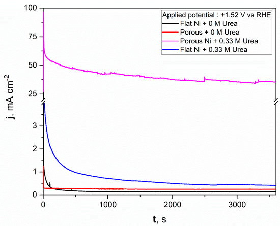
Figure 8.
The chronoamperometric scans registered for the unmodified Ni and Ni porous electrodes in 1 M NaOH with and without the 0.33 M urea in electrolyte.

Table 1.
UOR activity of different catalysts.
The obtained results show that the molten salt modification allowed for the formation of a highly active material in urea electrooxidation. If the activity were related to the surface area size, we would expect a current density only around 10 times higher (according to the double layer capacitance comparison) for a chronoamperometric experiment (Figure 8) than in the case of the bare Ni electrode. Surprisingly, the obtained current density value for urea electrooxidation at a potential of +1.52 V was 38 times higher, which additionally shows that the formed porous structure had a high number of electroactive centers on the electrode surface as voids and defects, where the activation energy for urea electrooxidation was taking place with lower activation energy. For our future works, we would like to confirm this based on kinetic studies related to activation energy estimation at different electrolyte temperatures and by application of various molten salt modification conditions.
4. Conclusions
Nickel porous electrodes obtained by molten salt treatment were successfully fabricated and tested as possible anode electrodes for the oxidation of urea in alkaline media.
Molten salt treatment performed at 750 °C did not change the chemical or phase composition of the nickel substrate.
Observed signals on XRD showed the remaining Ni-Al phases which were not dissolved completely during the anodic polarization scan.
Cyclic voltammetry scans in non-faradaic regions revealed the substantial increase in the electrochemical active surface of the porous electrode to around 50 cm2, which could be observed by SEM as a large number of nanometrical holes on the electrode surface. This is a possible reason why the porous sample exhibited significantly higher catalytic activity in comparison to the un-modified sample.
The data obtained in polarization measurements showed that the modification of nickel with molten salt treatment significantly enhances the rate of urea oxidation by over 40 times, which is a promising result in terms of design and tailoring of electrocatalytically active materials.
Author Contributions
Conceptualization, D.K. and M.F.; data curation, H.T.; funding acquisition, D.K.; investigation, D.K., M.F., H.T. and M.W.; methodology, P.Ż.; supervision, D.K. and M.F.; writing—original draft, D.K.; writing—review and editing, M.F., M.W. and P.Ż. All authors have read and agreed to the published version of the manuscript.
Funding
The research project is partly supported by program “Excellence initiative—research university” for the AGH University.
Data Availability Statement
The raw data supporting the conclusions of this article will be made available by the authors on request.
Conflicts of Interest
The authors declare no conflicts of interest.
References
- Fan, L.; Tu, Z.; Chan, S.H. Recent Development of Hydrogen and Fuel Cell Technologies: A Review. Energy Rep. 2021, 7, 8421–8446. [Google Scholar] [CrossRef]
- Sayed, E.T.; Eisa, T.; Mohamed, H.O.; Abdelkareem, M.A.; Allagui, A.; Alawadhi, H.; Chae, K.-J. Direct Urea Fuel Cells: Challenges and Opportunities. J. Power Sources 2019, 417, 159–175. [Google Scholar] [CrossRef]
- Protsenko, V.S. Thermodynamic Aspects of Urea Oxidation Reaction in the Context of Hydrogen Production by Electrolysis. Int. J. Hydrogen Energy 2023, 48, 24207–24211. [Google Scholar] [CrossRef]
- Protsenko, V.S.; Bobrova, L.S.; Butyrina, T.E.; Sukhatskyi, O.D. Thermodynamics of Electrochemical Urea Oxidation Reaction Coupled with Cathodic Hydrogen Evolution Reaction in an Alkaline Solution: Effect of Carbonate Formation. Int. J. Hydrogen Energy 2024, 59, 354–358. [Google Scholar] [CrossRef]
- Sun, Y.; Chen, S. New Electrocatalysts and Mechanisms Pave the Way to Urea Oxidation with Superior Activities and Stability. Sci. China Chem. 2022, 65, 199–201. [Google Scholar] [CrossRef]
- Daramola, D.A.; Singh, D.; Botte, G.G. Dissociation Rates of Urea in the Presence of NiOOH Catalyst: A DFT Analysis. J. Phys. Chem. A 2010, 114, 11513–11521. [Google Scholar] [CrossRef] [PubMed]
- Vedharathinam, V.; Botte, G.G. Direct Evidence of the Mechanism for the Electrooxidation of Urea on Ni(OH)2 Catalyst in Alkaline Medium. Electrochim. Acta 2013, 108, 660–665. [Google Scholar] [CrossRef]
- Xie, L.; Liu, Q.; Luo, Y.; Liu, Z.; Xu, Y.; Asiri, A.M.; Sun, X.; Xie, F. Bimetallic NiCoP Nanosheets Array for High-Performance Urea Electrooxidation and Less Energy-Intensive Electrolytic Hydrogen Production. ChemistrySelect 2017, 2, 10285–10289. [Google Scholar] [CrossRef]
- Xu, W.; Du, D.; Lan, R.; Humphreys, J.; Wu, Z.; Tao, S. Highly Active Ni–Fe Double Hydroxides as Anode Catalysts for Electrooxidation of Urea. New J. Chem. 2017, 41, 4190–4196. [Google Scholar] [CrossRef]
- Yang, D.; Yang, L.; Zhong, L.; Yu, X.; Feng, L. Urea Electrooxidation Efficiently Catalyzed by Nickel-Molybdenum Oxide Nanorods. Electrochim. Acta 2019, 295, 524–531. [Google Scholar] [CrossRef]
- Urbańczyk, E.; Jaroń, A.; Simka, W. Electrocatalytic Oxidation of Urea on a Sintered Ni–Pt Electrode. J. Appl. Electrochem. 2017, 47, 133–138. [Google Scholar] [CrossRef]
- Goda, M.A.; Abd El-Moghny, M.G.; El-Deab, M.S. Enhanced Electrocatalytic Oxidation of Urea at CuOx-NiOx Nanoparticle-Based Binary Catalyst Modified Polyaniline/GC Electrodes. J. Electrochem. Soc. 2020, 167, 064522. [Google Scholar] [CrossRef]
- Wu, M.-S.; Lin, G.-W.; Yang, R.-S. Hydrothermal Growth of Vertically-Aligned Ordered Mesoporous Nickel Oxide Nanosheets on Three-Dimensional Nickel Framework for Electrocatalytic Oxidation of Urea in Alkaline Medium. J. Power Sources 2014, 272, 711–718. [Google Scholar] [CrossRef]
- Chavhan, M.P.; Slovak, V.; Lu, C.-H. Thickness-Controlled Porous Hexagonal NiO Nanodiscs Electrodes for Use in Supercapacitors: How Nanodiscs Thickness Influences Electrochemical Performance. J. Energy Storage 2022, 50, 104329. [Google Scholar] [CrossRef]
- Navarro-Aguilar, A.I.; Ruíz-Gómez, M.A.; Rodríguez-González, V.; Obregón, S.; Vázquez, A. Effect of the Ni(NO3)2 Additive on the Electrophoretic Deposition of NiO Nanoparticles. Ceram. Int. 2020, 46, 28528–28535. [Google Scholar] [CrossRef]
- Tanaka, S.; Hirose, N.; Tanaki, T.; Ogata, Y.H. Effect of Ni-Al Precursor Alloy on the Catalytic Activity for a Raney-Ni Cathode. J. Electrochem. Soc. 2000, 147, 2242. [Google Scholar] [CrossRef]
- Dulle, J.; Nemeth, S.; Skorb, E.V.; Irrgang, T.; Senker, J.; Kempe, R.; Fery, A.; Andreeva, D.V. Sonochemical Activation of Al/Ni Hydrogenation Catalyst. Adv. Funct. Mater. 2012, 22, 3128–3135. [Google Scholar] [CrossRef]
- Bernäcker, C.I.; Rauscher, T.; Büttner, T.; Kieback, B.; Röntzsch, L. A Powder Metallurgy Route to Produce Raney-Nickel Electrodes for Alkaline Water Electrolysis. J. Electrochem. Soc. 2019, 166, F357–F363. [Google Scholar] [CrossRef]
- Adabi, M.; Amadeh, A.A. Formation Mechanisms of Ni–Al Intermetallics during Heat Treatment of Ni Coating on 6061 Al Substrate. Trans. Nonferrous Met. Soc. China 2015, 25, 3959–3966. [Google Scholar] [CrossRef]
- Nakajima, K.; Fukumoto, M. Porous Ni–Co Surface Formation and Analysis of Hydrogen Generation by Gas Sensor. Int. J. Hydrogen Energy 2021, 46, 26263–26271. [Google Scholar] [CrossRef]
- Fukumoto, M.; Takahashi, H.; Kutyła, D.; Wojnicki, M.; Żabiński, P. Morphological Investigation and Electrochemical Performance Evaluation of Novel Porous Ni–Pt Produced by Al-Deposition/Dissolution in Molten Salts for Hydrogen and Oxygen Evolution Reaction. Int. J. Hydrogen Energy 2024, 49, 754–765. [Google Scholar] [CrossRef]
- Kutyła, D.; Nakajima, K.; Fukumoto, M.; Wojnicki, M.; Kołczyk-Siedlecka, K. Electrocatalytic Performance of Ethanol Oxidation on Ni and Ni/Pd Surface-Decorated Porous Structures Obtained by Molten Salts Deposition/Dissolution of Al-Ni Alloys. Int. J. Mol. Sci. 2023, 24, 3836. [Google Scholar] [CrossRef] [PubMed]
- Fukumoto, M.; Sugiuchi, K.; Nakajima, K. Formation of Porous Ni Surface by Electrodeposition and Dissolution in Molten Salt. Int. J. Hydrogen Energy 2020, 45, 28252–28259. [Google Scholar] [CrossRef]
- Fukumoto, M.; Suzuki, T.; Hara, M.; Narita, T. Effect of the Electrodeposition Temperature on the Cyclic-Oxidation Resistance of Ni Aluminide Containing Zr Formed by Molten-Salt Electrodeposition. Mater. Trans. 2009, 50, 335–340. [Google Scholar] [CrossRef]
- Losertová, M.; Čech Barabaszová, K.; Drápala, J.; Kursa, M. Study of Kirkendall Effect in Ni/Ni3Al Welded Joint after the High Temperature Annealing. Defect. Diffus. Forum 2007, 263, 213–218. [Google Scholar] [CrossRef]
- Watzele, S.; Hauenstein, P.; Liang, Y.; Xue, S.; Fichtner, J.; Garlyyev, B.; Scieszka, D.; Claudel, F.; Maillard, F.; Bandarenka, A.S. Determination of Electroactive Surface Area of Ni-, Co-, Fe-, and Ir-Based Oxide Electrocatalysts. ACS Catal. 2019, 9, 9222–9230. [Google Scholar] [CrossRef]
- Connor, P.; Schuch, J.; Kaiser, B.; Jaegermann, W. The Determination of Electrochemical Active Surface Area and Specific Capacity Revisited for the System MnOx as an Oxygen Evolution Catalyst. Z. Phys. Chem. 2020, 234, 979–994. [Google Scholar] [CrossRef]
- Anantharaj, S.; Sugime, H.; Noda, S. Why Shouldn’t Double-Layer Capacitance (Cdl) Be Always Trusted to Justify Faradaic Electrocatalytic Activity Differences? J. Electroanal. Chem. 2021, 903, 115842. [Google Scholar] [CrossRef]
- McCrory, C.C.L.; Jung, S.; Ferrer, I.M.; Chatman, S.M.; Peters, J.C.; Jaramillo, T.F. Benchmarking Hydrogen Evolving Reaction and Oxygen Evolving Reaction Electrocatalysts for Solar Water Splitting Devices. J. Am. Chem. Soc. 2015, 137, 4347–4357. [Google Scholar] [CrossRef]
- Li, Y.; Luo, F.; Xie, Y.; Chang, C.; Xie, M.; Yang, Z. Oxygen Vacancies in α-Ni(OH)2 Porous Nanoflowers Promote Urea Oxidation. Int. J. Hydrogen Energy 2023, 48, 9155–9162. [Google Scholar] [CrossRef]
- Guo, F.; Ye, K.; Cheng, K.; Wang, G.; Cao, D. Preparation of Nickel Nanowire Arrays Electrode for Urea Electrooxidation in Alkaline Medium. J. Power Sources 2015, 278, 562–568. [Google Scholar] [CrossRef]
- Gómez-Sacedón, C.; López-Fernández, E.; González-Elipe, A.R.; Espinós, J.P.; Yubero, F.; Gil-Rostra, J.; de Lucas-Consuegra, A. NiFeO/NiFe Bilayer Electrocatalyst for an Efficient Urea Assisted Water Electrolysis. Int. J. Hydrogen Energy 2024, 59, 604–613. [Google Scholar] [CrossRef]
- Adhikari, S.; Kwon, Y.; Kim, D.-H. Three-Dimensional Core–Shell Structured NiCo2O4@CoS/Ni-Foam Electrocatalyst for Oxygen Evolution Reaction and Electrocatalytic Oxidation of Urea. Chem. Eng. J. 2020, 402, 126192. [Google Scholar] [CrossRef]
- Yang, W.; Yang, X.; Hou, C.; Li, B.; Gao, H.; Lin, J.; Luo, X. Rapid Room-Temperature Fabrication of Ultrathin Ni(OH)2 Nanoflakes with Abundant Edge Sites for Efficient Urea Oxidation. Appl. Catal. B 2019, 259, 118020. [Google Scholar] [CrossRef]
- Zhang, J.-Y.; He, T.; Wang, M.; Qi, R.; Yan, Y.; Dong, Z.; Liu, H.; Wang, H.; Xia, B.Y. Energy-Saving Hydrogen Production Coupling Urea Oxidation over a Bifunctional Nickel-Molybdenum Nanotube Array. Nano Energy 2019, 60, 894–902. [Google Scholar] [CrossRef]
Disclaimer/Publisher’s Note: The statements, opinions and data contained in all publications are solely those of the individual author(s) and contributor(s) and not of MDPI and/or the editor(s). MDPI and/or the editor(s) disclaim responsibility for any injury to people or property resulting from any ideas, methods, instructions or products referred to in the content. |
© 2024 by the authors. Licensee MDPI, Basel, Switzerland. This article is an open access article distributed under the terms and conditions of the Creative Commons Attribution (CC BY) license (https://creativecommons.org/licenses/by/4.0/).