Abstract
This study investigates active filling friction stir repair (AF-FSR) and passive filling friction stir repair (PF-FSR) for repairing AISI 304 stainless steel sheets, focusing on addressing the challenges posed by high melting point metals. The research involved repairing overlapping 2 mm thick sheets with pre-drilled holes of 2, 4, and 6 mm diameters, simulating broken components. Various process parameters, including rotational speed, dwell time, and the use of metal fillers, were tested to evaluate their impact on repair quality. The results demonstrated that PF-FSR provided superior mechanical strength to AF-FSR, particularly for larger pre-hole diameters. PF-FSR achieved higher shear tension strength due to better defect filling and reduced void formation, with shear tension strengths exceeding 25 kN for larger pre-holes and lower variability in strength measurements. AF-FSR was less effective for larger pre-holes, resulting in significant voids and reduced strength. Microstructural analysis revealed that PF-FSR facilitated more efficient material mixing and filling, minimizing unrepaired regions. However, excessive rotational speeds and dwell times in PF-FSR led to deformation and flash formation, highlighting the need for optimal parameter selection. Although further studies are needed, this study confirms the feasibility of FSR techniques for repairing small defects in AISI 304 steels, offering valuable insights for sustainable manufacturing practices in industries such as automotive and aerospace, where efficient and reliable repair methods are critical.
1. Introduction
Driven by environmental changes, industrial and political authorities are increasingly focusing on the efficient use of energy and resources. Jawahir et al. [1] highlighted that the traditional linear economy model, characterized by the “take-make-dispose” logic, is inadequate for facing global sustainability challenges. Duflou et al. [2] detailed the actions necessary to implement the “6R methodology” in industrial practices, as illustrated in Figure 1. “Repair action” refers to correcting specified faults in a product. The primary aim of repair is to restore a product or component to a functional condition after a failure has been detected, whether during service or after it has been wasted. This practice can sometimes directly involve the product user. In contrast, remanufacturing involves a more intensive process that typically requires returning the product to the manufacturing plant. The terms “repair” and “remanufacturing” are often used interchangeably in the literature.
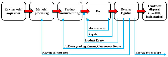
Figure 1.
The implementation of the “6R methodology” in industrial practice (adapted from [2]).
According to the state-of-the-art, different technologies (e.g., additive manufacturing—AM, laser cladding, welding processes) have been adapted to repair structural components. For instance, direct energy deposition (DED) is an AM process used to repair metal component defects. It effectively fills cracks, addresses wear and erosion, and rebuilds corroded areas, extending the service life of parts like turbine blades and cutting tools. This makes DED valuable in industries such as aerospace, automotive, power generation, and tooling. Saboori et al. [3] reported a list of case studies in which DED was applied to repair components made of steels (e.g., mold, tools, rails, vessels, crankshaft, driveshaft, marine piston) and Ni-based superalloy (e.g., gas turbine compressor seal, high-pressure turbine blades, turbine airfoils, thin-curved compressor blade). Deng et al. [4] used resistance spot welding (RSW) to close holes in aluminum plates by adding an external metal filler. However, these approaches require material melting, with a consequent harmful effect on microstructures [5,6].
For these reasons, different techniques have also been developed to repair metal parts in the solid state, limiting the detrimental effects of melting. Friction stir spot welding (FSSW) has been proposed for repairing small-sized defects (roughly smaller than 10 mm) on metal parts [7,8,9,10,11,12]. In such cases, FSSW refers to active filling friction stir repairing (AF-FSR), also known as self-refilling friction stir welding [7,8], when the defect is filled without adding external material. Differently, the process is called passive filling FSR (PF-FSR) [13], also known as friction stir plug welding [12]. FSR has been typically used to repair keyholes left during previous friction stir welding (FSW) or FSSW processes [7,8]. FSW and FSSW keyholes are weak regions of the component due to the lack of material and, often, are also characterized by uncontrolled residual stresses having negative effects on fatigue life [14,15]. Another common use of AF- and PF-FSR is in closing casting defects [16,17], especially in aerospace applications, where pores, cavities, and cracks in cast aluminum alloys must be repaired to prevent a reduction in performance [18,19].
Metal Component Repair with FSSW Techniques
AF-FSR was used for aluminum alloys [7] and for stainless steels [8] to repair keyholes left during a previous lap FSSW process. Sajed [7] investigated the effects of dwell time, plunge depth, refilling shoulder diameter, and rotational speed on the mechanical properties of 2 mm thick AA1100 plates. ANOVA results revealed that rotational speed and shoulder diameter are the most important parameters affecting tensile shear strength, followed by refilling shoulder diameter. The strength of refilled specimens increased with decreasing rotational speed (from 2000 to 1000 rpm) and increasing shoulder diameter (from 10 to 18 mm). Zhou et al. [8] focused on AISI 316L using a relatively low dwell time of 5 s and a rotational speed range of 1200–1500 rpm with a multistage AF-FSR until the refill (about 3 mm deep) was achieved. The authors performed TEM analysis in the SZ and found no evidence of the sigma phase. The direct decomposition of austenite into the sigma phase requires a long time due to the necessary redistribution of alloying elements through substitutional diffusion. While sigma formation can be accelerated under the high strain and recrystallization induced by friction stirring, the authors highlighted that the holding time was only 5 s for each step. Therefore, the high-temperature retention time was relatively short, preventing the formation of the sigma phase in the SZ. The authors also observed rod-like carbides, several hundred nanometers in size, along the grain boundaries in the SZ. However, this phenomenon did not cause Cr depletion and degradation of corrosion resistance. In austenitic stainless steel, Cr23C6 is the most common carbide. The authors also identified the Cr7C3 phase with a trigonal structure in the SZ. Typically, the sigma phase forms in austenitic stainless steel during aging at temperatures between 500 and 800 °C. Finally, tensile test results showed that specimens fractured at the base material (BM), with ultimate tensile strength (UTS) and elongation at fracture being 112% and 82% of the BM, respectively.
AF-FSR is effective for closing two-dimensional defects with small thicknesses, while PF-FSR is more suitable for volume defects [9]. PF-FSR was applied to magnesium [9,10,11] and aluminum alloys [12,13,16,17]. Qi et al. [9] focused on 3 mm thick AZ31 plates using a metal filler, with a height of 0.5 mm higher than the depth of the drilled hole (2.5 mm deep and 10 mm in diameter) to avoid thickness reduction. The authors used a fixed dwell time of 20 s and a varying rotational speed from 1200 to 1600 rpm to repair the AZ31 plates. A maximum UTS of 183 MPa was obtained with 1400 rpm, equivalent to 93.8% of that from a plate without a repaired hole. UTS decreased at 1600 rpm due to the excessive softening induced by heat input. Huang et al. [10] studied the feasibility of PF-FSR on 3 mm thick AZ31B plates considering a hole (1.5 mm deep and 10 mm in diameter) filled with a 2 mm thick metal filler. They examined the effect of plunge depth (0.2–0.6 mm range) with a 20 s dwell time and 1600 rpm rotational speed. Maximum UTS and elongation at fracture (217 MPa and 8%, respectively) were reached at 0.4 mm plunge depth because of the improved frictional heat and bonding at the interface between the metal filler and BM. However, these properties decreased with a plunge depth above 0.4 mm due to significant thickness reduction. Sajed et al. [12] demonstrated that multistage PF-FSR is also suitable for filling large voids with a diameter of 16 mm and depth of 10 mm in aluminum plates. They reported that high rotational speeds (3000 rpm) are essential for sufficient heat input, but low dwell times (5 s) should be used to avoid cracks during the process. Wen et al. [16,17] demonstrated the feasibility of PF-FSR for closing cavities in casting defects in 6 mm thick ZL210 aluminum alloy. The casting defects were first drilled into holes (1.5 mm deep and 14 mm in diameter) using a 2 mm long metal filler.
An alternative PF-FSR configuration with a consumable pin has been effectively used in aluminum alloys (2.5–7.8 mm thickness) to fill the exit hole left during the previous FSW process [20,21,22,23]. In these cases, UTS and elongation of at least 80–90% of those of the BMs were achieved [20,21,22]. Meng et al. [23] found that the tool pin conical angle strongly influences both load transfer and material flow. Moreover, optimizing this angle was essential to prevent pin fracture before the dwelling stage. The authors reported that sound components were achieved when the pin conical angle was 1° larger than that of the volumetric defect.
The literature review on FSR-based techniques for component repair has revealed two significant research gaps. Previous studies only applied the FSR technique to a single plate. In contrast, this study involves two overlapped 2 mm thick sheets to simulate a completely broken component. Moreover, the literature predominantly focuses on low melting point metals, such as aluminum and magnesium alloys, due to their low tool wear rates and minimal frictional heat inputs. This research aims to extend the use of FSR to high melting point metals. Among these, repairing stainless steel components is particularly critical due to the high cost of alloying elements [24]. Stainless steels are used in second-generation automotive steels, aerospace sector, rail transport and in many other industries. Solid-state techniques are necessary for processing these steels to avoid embrittlement caused by excessive heat inputs [25,26]. Consequently, this study has selected AISI 304 as the material for the case study, considering that this austenitic steel accounts for approximately 70% of the total stainless steel production [24].
2. Materials and Methods
Commercial 2 mm thick AISI 304 cold rolled sheets have been examined in this study. The chemical composition of such material is listed in Table 1.

Table 1.
Chemical composition (wt.%) of the AISI 304 sheets, as from the supplier’s technical datasheet.
During the experimental trials, a series of two coupons, each measuring 125 × 40 mm, were overlapped by 40 mm and repaired in the middle of this overlap using AF-FSR and PF-FSR technologies, as shown in Figure 2. The upper sheets, positioned on the same side as the repairing tool, featured 2, 4, or 6 mm pre-holes in their centers to simulate components with varying degrees of surface damage.
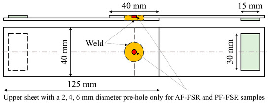
Figure 2.
Schematic illustration of the overlapped coupons subjected to AF-FSR, PF-FSR, and P-FSSW. The red area highlights the pre-hole in the upper sheets for AF-FSR and PF-FSR. Such samples were also used as shear tension samples.
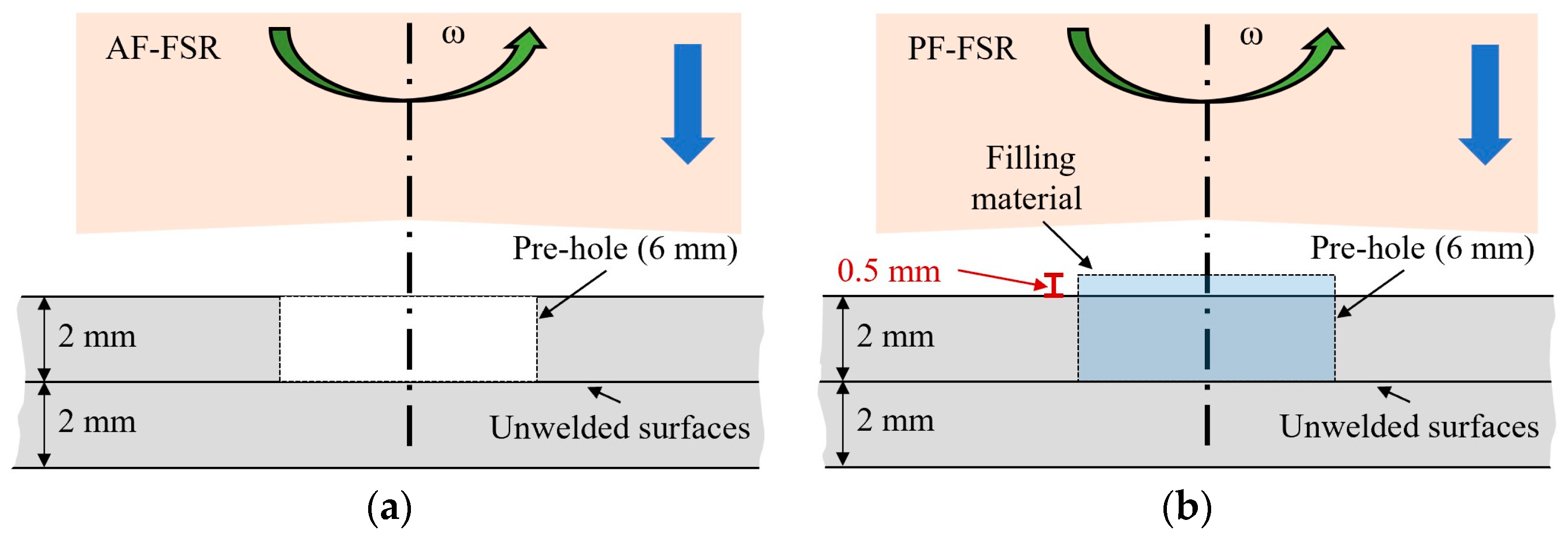
Preliminary pilot experimentations were conducted based on the literature. Then, sheets were repaired through AF-FSR and PF-FSR according to the process parameters reported in Table 2. The plunge speed was 50 mm/min to minimize the process cycle time [27]. The dwell time ranged between 10 and 20 s, with higher values selected for pre-hole diameters of 4 and 6 mm. The tool rotational speed has been limited as much as possible to minimize the peak temperature in the sheet stack, responsible for the potential formation of brittle delta ferrite [28], while still ensuring the hole repair (up to 1500 rpm for a 6 mm pre-hole). During PF-FSR, a disk-shaped metal filler (2.5 mm thick) was used to repair defects simulated by 4 and 6 mm pre-holes. A metal filler serves to face the material loss as a flash, which typically occurs for such friction repair processes [10,11]. Figure 3 shows a schematic illustration of AF-FSR and PF-FSR techniques.
Table 2.
Sheet stack configurations and process parameters.
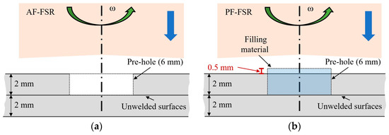
Figure 3.
Schematic illustration of (a) AF-FSR and (b) PF-FSR processes. Example for a pre-hole diameter of 6 mm. Arrows show the roto-translation motion of the tool pin.
In addition to the AF- and PF-FSR repaired regions, some joints were realized using pinless-FSSW (P-FSSW) on undrilled upper sheets to compare their mechanical properties and material flow with those of conventional P-FSSW joints. For the P-FSSW condition, process parameters like those used in the AF-FSR and PF-FSR techniques were applied.
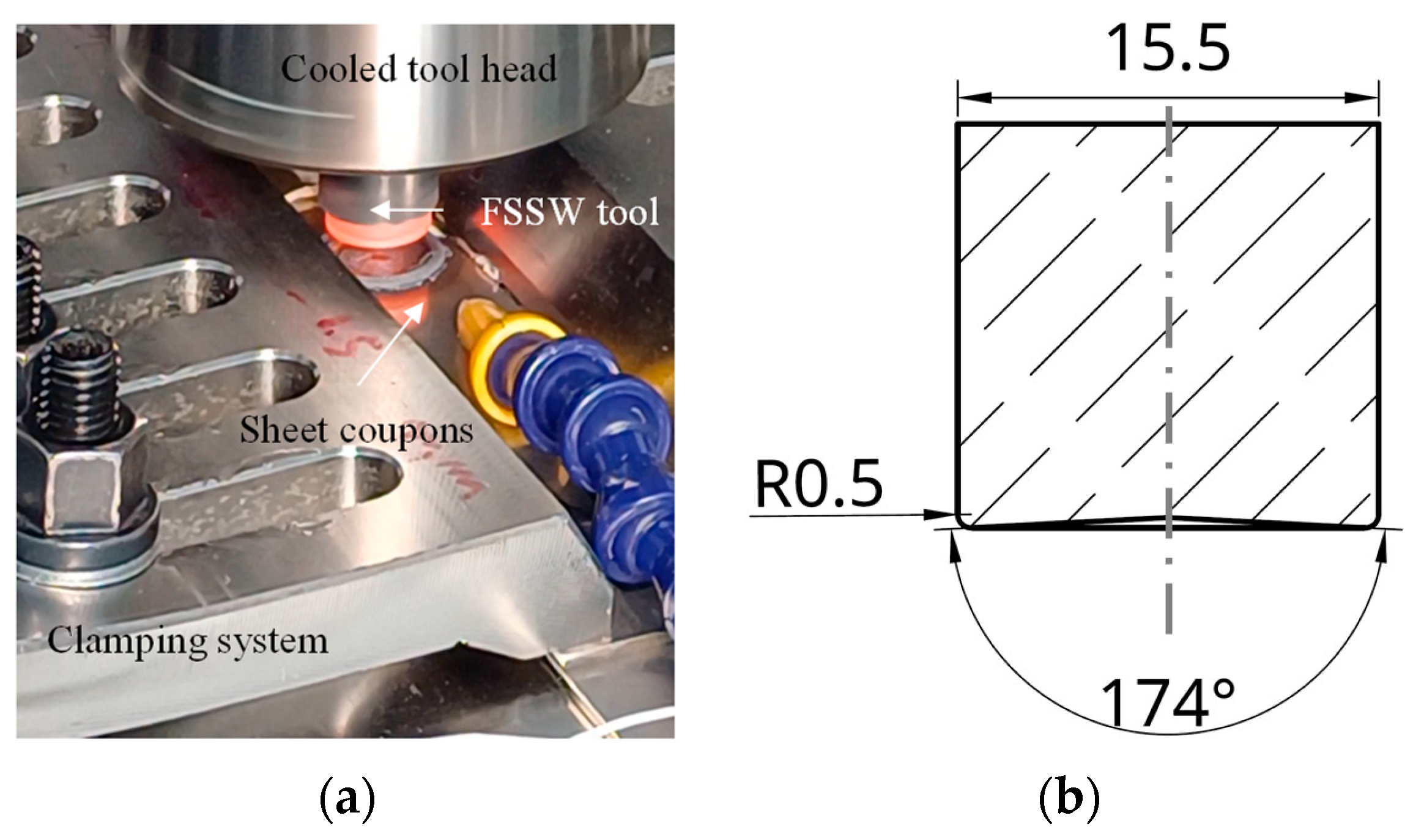
The sheet stacks were repaired using a 100 kN FSW machine (Stirtec GmbH, Kalsdorf, Graz, Austria) equipped with a water-cooled spindle (Figure 4a). The tool was made of tungsten–rhenium alloy (75 wt.% W, 25 wt.% Re) to withstand the high temperatures achieved during repairs (Figure 4b). A pinless tool with a concave shoulder was selected to effectively promote material flow towards the center to fill the pre-hole. The concave shoulder helps to limit the lateral flash, keeping the flowing material under the shoulder. The same machine and tool were used to carry out the P-FSSW tests.

Figure 4.
(a) Equipment and (b) tool geometry used for the repair tests.
Shear tension tests were performed to assess the mechanical strength of the repaired samples. The dimensions of the sheet stacks were selected based on the JIS Z 3136 standard (Figure 2) [29]. Shims (30 mm × 15 mm × 2 mm) were attached to the ends of the repaired and P-FSSW samples to ensure the center of the sheet stack aligned with the direction of the tensile load. The shear tension tests were carried out with a universal testing machine with a 10 mm/min crosshead speed. The shear tension strength was evaluated as the peak load was reached during the test, and the elongation at the peak load was also determined. At least three tensile samples were prepared for each sheet stack configuration to ensure consistent results. The cross-sections of the repaired samples were examined through optical microscopy. Metallographic samples were prepared using a standard procedure, including grinding, polishing, and final chemical etching with a Kroll’s etchant. The grain size obtained in the different repaired samples was measured according to the ASTM E112 standard [30].
3. Test Results and Their Analysis
3.1. AF-FSR, PF-FSR, and P-FSSW Process Parameters
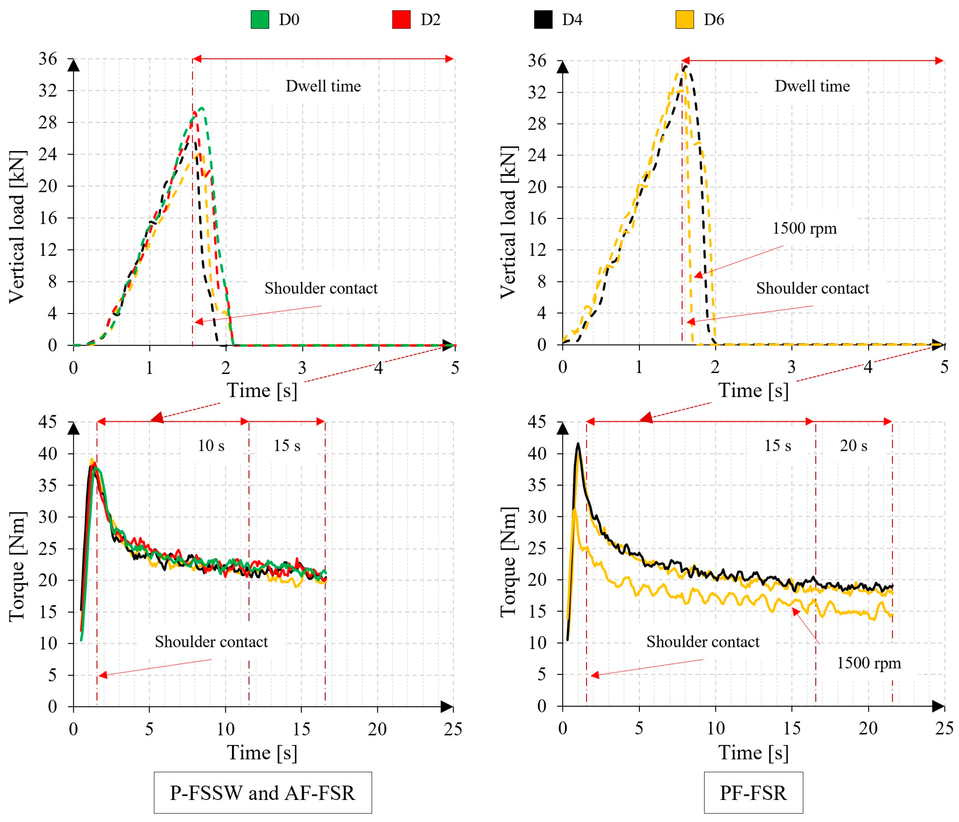
Figure 5 shows the vertical force and spindle torque required during the repair process. Unless otherwise noted, all data were recorded at a rotational speed of 1000 rpm. Data are labeled based on the diameter of the pre-holes, where, e.g., “D2” means a 2 mm pre-hole. For comparison, Figure 5 also reports the data monitored during the P-FSSW trial, marked as “D0” due to the absence of a pre-hole. Overall, the data show a similar trend for all samples. The vertical tool force increases as the shoulder penetrates the upper sheet during the initial plunge phase, reaching a maximum at the end of tool plunging (1.3 mm). As expected, the maximum force is lowest for the AF-FSR samples with the largest pre-hole and increases as the pre-hole size decreases due to the presence of more material to be mixed. Regardless of the pre-hole diameter (4 or 6 mm), the force reaches the maximum peak at 36 kN in the PF-FSR process. This is attributed to the presence of metal filler exceeding the sheet stack by 0.5 mm. P-FSSW, instead, shows an intermediate peak value of 30 kN since the upper sheet had neither a pre-hole nor a metal filler. After ending the plunge phase, the vertical force abruptly drops to about 0.1 kN in both repair approaches due to the metal softening occurring after the beginning of the dwell phase. This force reduction is also associated with the lateral squeeze of the metal under the shoulder, forming a flash, as shown in Figure 6, Figure 7 and Figure 8 and reported in other studies [27].
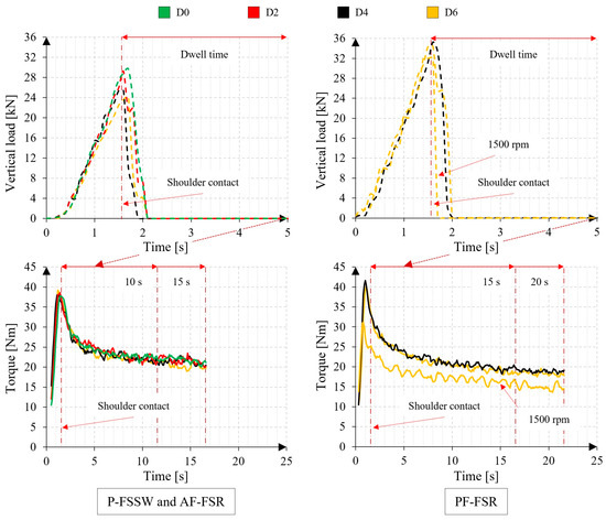
Figure 5.
P-FSSW, AF-FSR, and PF-FSR processes: vertical force [kN] and spindle torque [Nm].
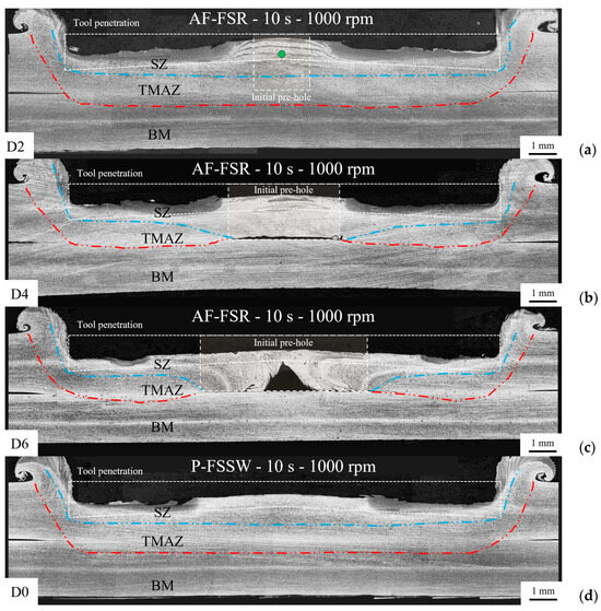
Figure 6.
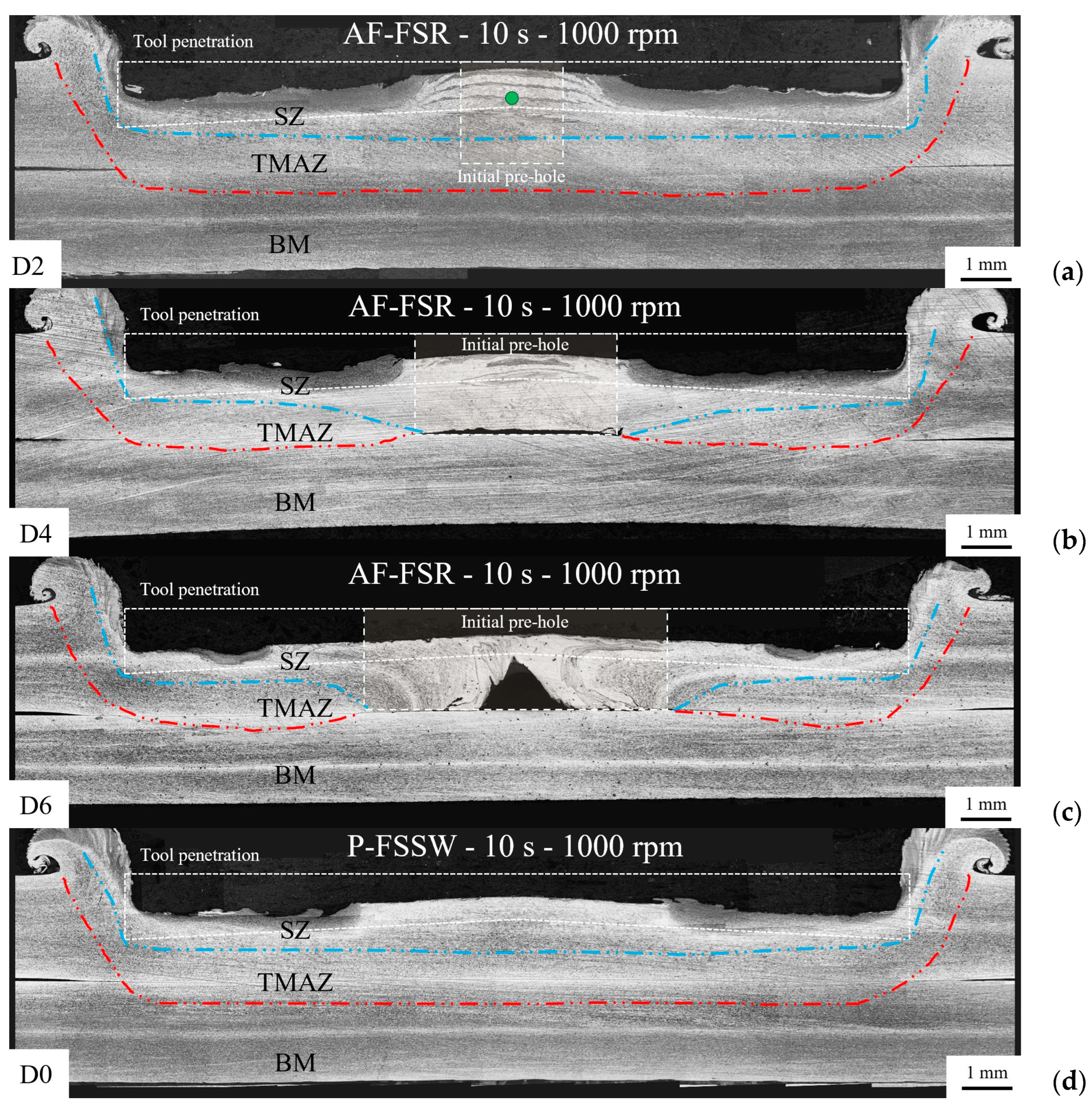
Cross-section of repaired samples obtained through AF-FSR (1000 rpm and 10 s dwell time) with different pre-hole diameters: (a) 2 mm (D2); (b) 4 mm (D4); (c) 6 mm (D6). Image (d) refers to the typical cross-section of a P-FSSW joint (no pre-hole, D0). The white dotted lines refer to the upper sheets before AF- or P-FSSW. The green-colored circle in the image (a) highlight the location of the microstructure reported in Figure 10c.
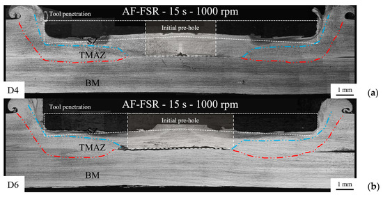
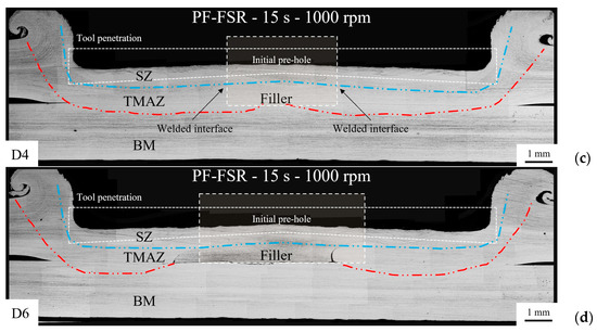
Figure 7.
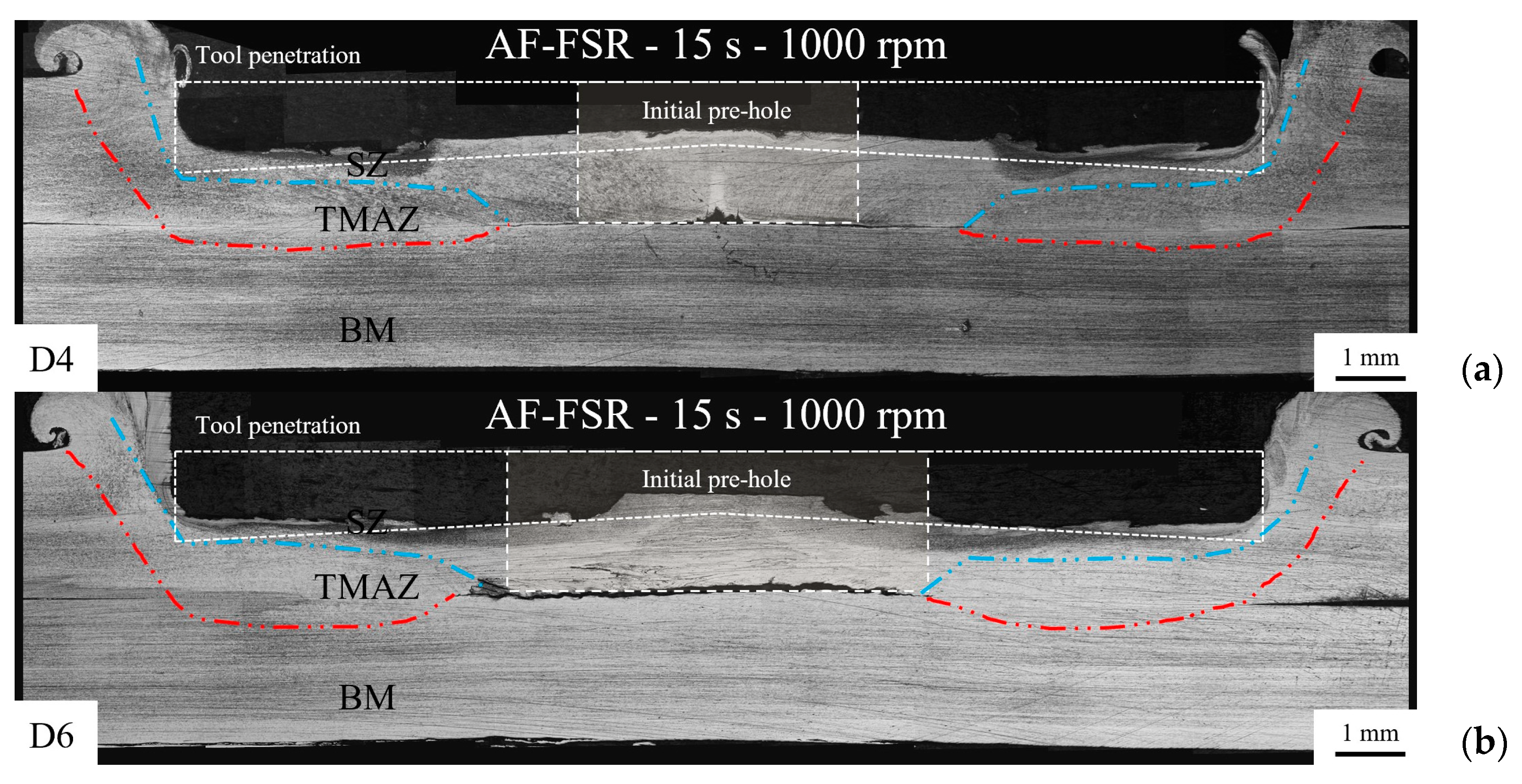
Cross-section of repaired samples obtained through AF- and PF-FSR (1000 rpm and 15 s dwell time) with different pre-hole diameters: (a) AF-FSR 4 mm (D4); (b) AF-FSR 6 mm (D6); (c) PF-FSR 4 mm (D4); (d) PF-FSR 6 mm (D6).
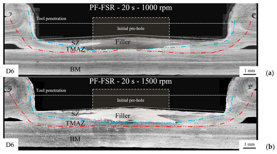
Figure 8.
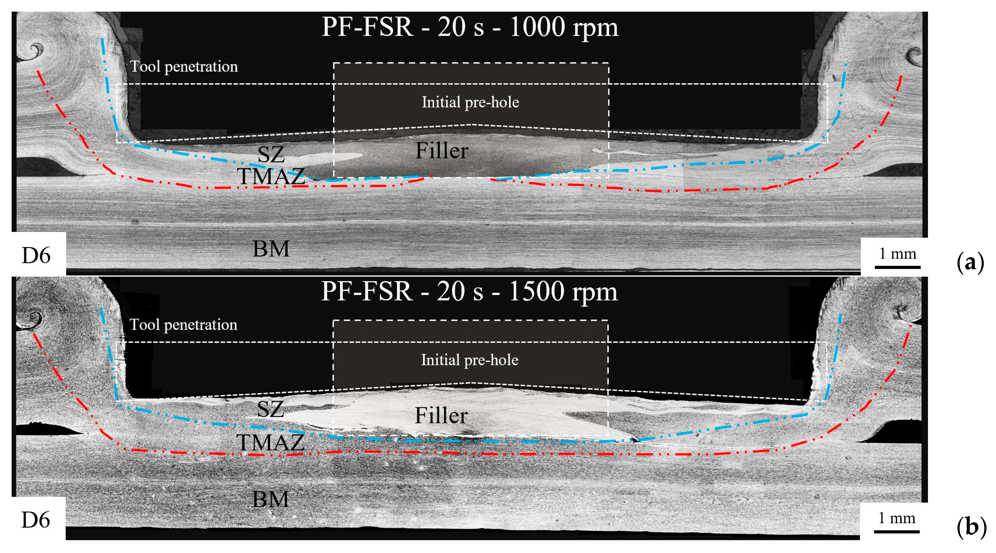
Cross-section of PF-FSR samples with a 6 mm pre-hole obtained with a dwell time of 20 s at varying tool rotational speeds: (a) 1000 rpm and (b) 1500 rpm.
No significant differences in torque values have been detected in all the conditions investigated. Therefore, torque is independent of the presence of a pre-hole diameter (AF-FSR) and metal filler (PF-FRS). Overall, the spindle torque steadily increases, peaking at about 40 Nm during the plunging phase. Then, it slightly decreases during the dwelling stage coherently with metal softening. This observation is also relevant to PF-FSR samples since the material flow under the tool shoulder is similar to what occurs for PF-FRS. Moreover, studies have found that in these processes torque is less sensitive than force at varying process settings [27].
For PF-FSR samples with a pre-hole diameter of 6 mm, increasing the rotational speed to 1500 rpm reduced the peak vertical force by about 2 kN. The force drop occurred faster (about 0.2 s) after the beginning of the dwell phase, presumably due to the higher temperature achieved in the material because of the higher tool rotational speed. For the same reason, the spindle torque peak decreases from 40 (1000 rpm) to 30 Nm. During the dwell phase, this difference gradually reduced to about 5 Nm due to the stronger softening and material flow squeezing as a flash.
The reviewed studies in the introduction section on FSR-based techniques of aluminum and magnesium alloys do not focus on the monitoring of process parameters. However, friction-stir-based techniques, such as butt FSW of high-strength aluminum alloys (4 mm thick), typically require lower vertical loads (i.e., about 6 kN) and torques (i.e., about 12 Nm) of those shown in Figure 5 [31].
3.2. Microstructure Examination
The cross-sections of the repaired AF-FSR and PF-FSR, as well as of the P-FSSW samples, are displayed in Figure 6, Figure 7 and Figure 8. They show the typical microstructural regions resulting from a solid-state friction process, namely the stir zone, SZ (the region heavily deformed by the tool stirring), and the thermo-mechanically affected zone, TMAZ. As also reported in some studies [32], the heat-affected zone (HAZ) is, instead, rather limited and not so noticeable in all samples. All the cross-sections feature two rectangles outlined with a white dotted line. The larger rectangle identifies the tool position during the dwell phase, while the smaller rectangle identifies the position of the pre-holes in AF-FSR or the metal filler in PF-FSR. Figure 6 displays the cross-section of samples obtained via AF-FSR and P-FSSW (used for comparison) with a dwell time of 10 s and a rotational speed of 1000 rpm. In AF-FSR repaired samples, the SZ extension progressively increases with the increase in the pre-hole diameter because of the larger amount of material that flowed under the tool shoulder in the repair process. Figure 6a shows the capability of AF-FSR in repairing the simulated defect by filling the 2 mm pre-hole. Conversely, a dwell time of 10 s and a rotational speed of 1000 rpm do not allow effective repair of the simulated damage through AF-FSR. Large unrepaired regions remain coherently in the center of the pre-hole with the lower angular speed of the tool (i.e., lower heat input and metal mixing). Comparing Figure 6b,c, the increase of the pre-hole diameter from 4 to 6 mm revealed a rise of the unfilled region in cross-section from an area of approximately 0.4 mm2 to 1.2 mm2. As a comparison, the typical cross-section of the P-FSSW, shown in Figure 6d, shows a joint without defects due to the absence of the pre-hole in such an examined condition.
Since the 10 s dwell time was insufficient to fill the pre-hole, this time was extended to 15 s, at 1000 rpm, to promote a larger heat input in the repaired region and, hence, stronger material mixing. Figure 7 reports the cross-sections of AF- and PF-FSR samples with pre-hole diameters of 4 and 6 mm obtained with such conditions. In AF-FSR, the larger heat input has led to a reduction of the unfilled central region. For instance, the increased dwell time reduced the cross-section of the unfilled region from approximately 0.4 mm2 to 0.2 mm2 (Figure 6b and Figure 7a, with a 4 mm pre-hole diameter) and from 1.2 mm2 to 0.7 mm2 (Figure 6c and Figure 7b, with a 6 mm pre-hole diameter). The largest pre-hole remains more difficult to repair, and a void, with the same diameter as the previous pre-hole, appears in the center of the repaired region (Figure 7b). The metal filler allows repair through PF-FSR of the samples with a 4 mm pre-hole (Figure 7c). This remains unfeasible with the largest pre-hole: a significant unrepaired region is between the initial metal filler and the upper sheet. Voids are also between the lateral surface of the metal filler and the upward metal of the upper sheet caused by insufficient frictional heat and metal mixing. The absence of the more limited unrepaired regions showcases the importance of a metal filler and, hence, the superior performance of PF-FSR over AF-FSR.
According to Table 2, further trials of PF-FSR were also performed with a dwell time of 20 s at 1000 and 1500 rpm to completely repair the 6 mm pre-hole. AF-FSR trials with similar process parameters revealed an excessive distortion of the sheet stack due to the absence of a metal filler. Therefore, such conditions were not evaluated for this repair technique. As shown in Figure 8a,b, an increase in the dwell time leads to an excess of heat input that, even though it ensures a full filling closure of the pre-hole, brings an excessive deformation of the metal filler, forming a notable flash and thinning of the repaired region, especially when a rotational speed of 1500 rpm is selected.
The use of FSR-based techniques to aluminum and magnesium alloys revealed a strong capability in repairing components with respect to what was highlighted in the results of this study of stainless steels. In most of the cases, only gaps or kissing bond defects were noticed with thicknesses in the range of 10–30 μm [10,13,16,17]. These defects were evident at the interfaces between surfaces (e.g., metal filler and damaged component) and were attributed to the low material flow velocity and low temperature. On the other hand, larger refilling defects with an area of about 2 mm2 were measured at the bottom of keyholes when considering the filling of large voids (diameter of 16 mm and depth of 10 mm) in aluminum plates [12]. The authors explained that in such cases, cavities should be closed at the early stages of the process using pinless tools. Moving to the study of Zhou et al. [8] about AISI 316L steel, the authors managed to fill the cavity (about 3 mm deep), producing only small cavities or gaps (about 5 μm thick) in the refilled area thanks to a multistage AF-FSR procedure. Those defects may have been caused by the low thermal conductivity and high plastic deformation resistance of AISI 316L. These two characteristics of stainless steels, as well as the original unwelded configuration of the sheet stack implemented in this study, could be the reason for the larger defect sizes shown in Figure 6 and Figure 7.
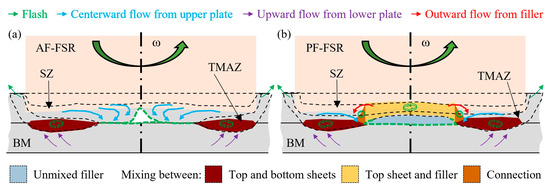
Figure 9 shows the schematic material flows beneath the tool during AF-FSR and PF-FSR based on the cross-section of Figure 6c and Figure 7d (6 mm pre-holes). In the AF-FSR, the shoulder friction with the upper sheet generates an inward metal flow towards the center, filling the pre-hole, and an outward flow, forming the lateral flash. The heat input also softens the lower plate, which is thermo-mechanically stirred, producing an upward flow that mixes with the upper sheet (red regions in Figure 9a). In PF-FSR (Figure 9b, the presence of a metal filler helps repair the simulated defect. The friction with the shoulder softens the metal filler and promotes its mixing with the upper sheet, as evidenced by the yellow region. In addition, further metal from the softened lower sheet (red regions) was mixed with the metal filler and upper sheet, as shown in the orange area. The bottom area of the metal filler can mix partially with the formation of an unrepaired area (Figure 7d) or completely with the lower plate (Figure 8a,b) based on the heat input associated with the welding settings (Table 2).
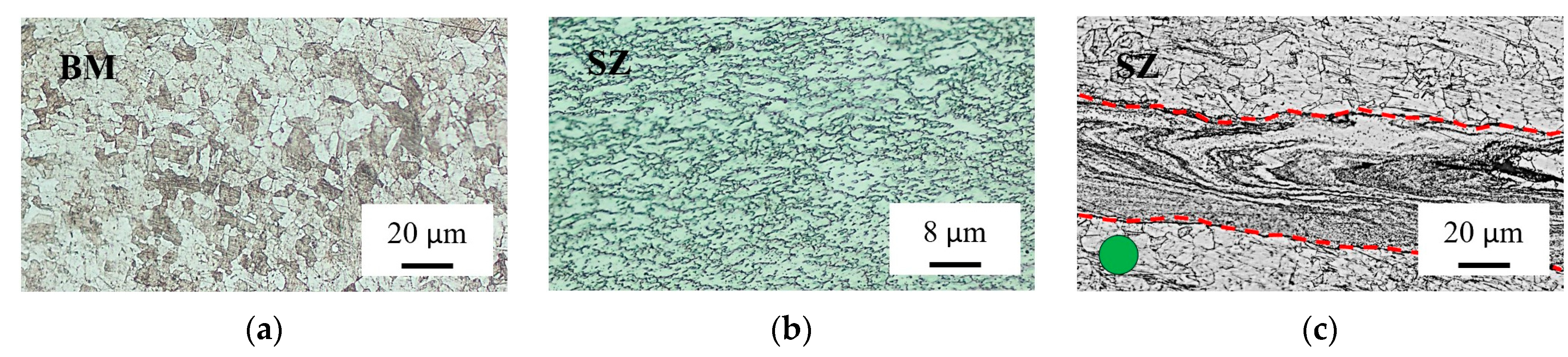
During the repairing processes, the SZ is heavily strained by the tool action, especially as metal flows during the filling of the pre-hole, with the grain size reducing from approximately 10 μm of the BM (Figure 10a) to a few microns of the SZ (Figure 10b). On the other hand, the dwell time increase from 10 to 20 s left a grain size in the SZ of about 10 μm as that of the BM. The larger grain size was measured by Zhou et al. [8] for the SZ (about 10 μm) of an AISI 316L plate (10 mm thick) processed via AF-FSR, probably due to the superior initial dimension of the BM (30–80 μm).
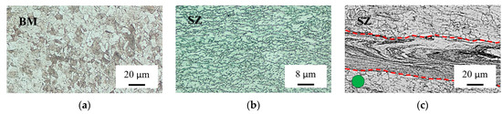
Figure 10.
Typical microstructures of the (a) BM and (b) SZ of the repaired AF- and PF-FSR regions. In addition, (c) an example of inhomogeneous metal flow lines (enclosed in the red dotted lines) found in some AF-FSR samples, as found in the location of the metallographic image highlighted by the green-colored circle in Figure 6a.
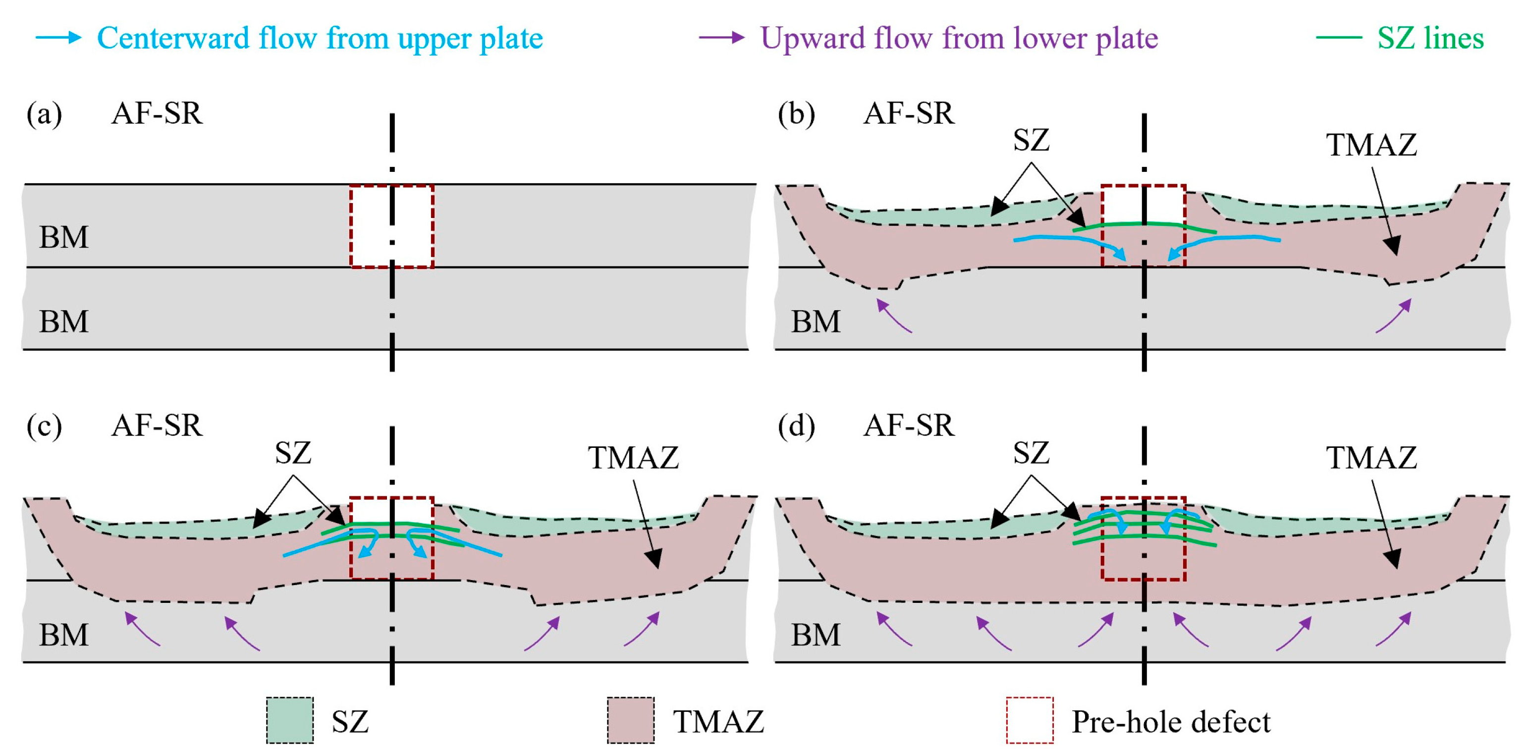
When the heat input and the metal mixing are insufficient, characteristic metal flow lines appear in the repaired regions. These lines are visible in Figure 6a,b during the incomplete AF-FSR repair and are outlined by the metallographic image of Figure 10c, located at the green-colored point of Figure 6a. The formation of these metal flow lines is schematically described in Figure 11. The final shapes of SZ and TMAZ were drawn from the cross-section of Figure 6a for a D2 case. For smaller pre-hole diameters (2 and 4 mm), the flow lines consolidated beneath the tool and transformed into alternating bands of TMAZ and SZ, as shown in Figure 6a,b. These features result from alternating between the centerward flow filling the central cavity and the subsequent squeezing and mixing under tool action. Zhou et al. [8] observed similar features in the AF-FSR of AISI 316L and concluded that this phenomenon is typical of friction-stir-based processes. Huang et al. [22] noticed similar flow lines in the upper part of the repaired sample made of an aluminum alloy using a PF-FSR-based process that uses a consumable pin. The authors reported that this region typically experiences extreme deformation and frictional heating due to contact with the shoulder.
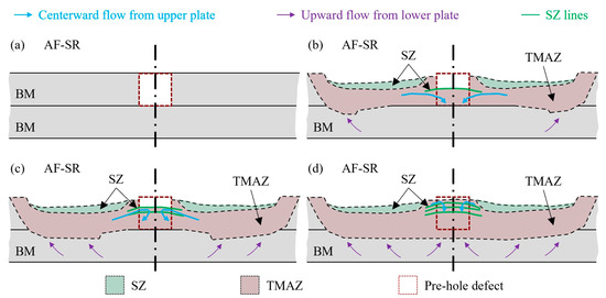
Figure 11.
Schematic material flows beneath the tool during AF-FSR divided into four subsequent steps: (a–d) The final shape of SZ and TMAZ were drawn for a D2 case from the cross-section of Figure 6a and marked off by black dotted lines.
3.3. Sheet Stack Shear Tension Strength
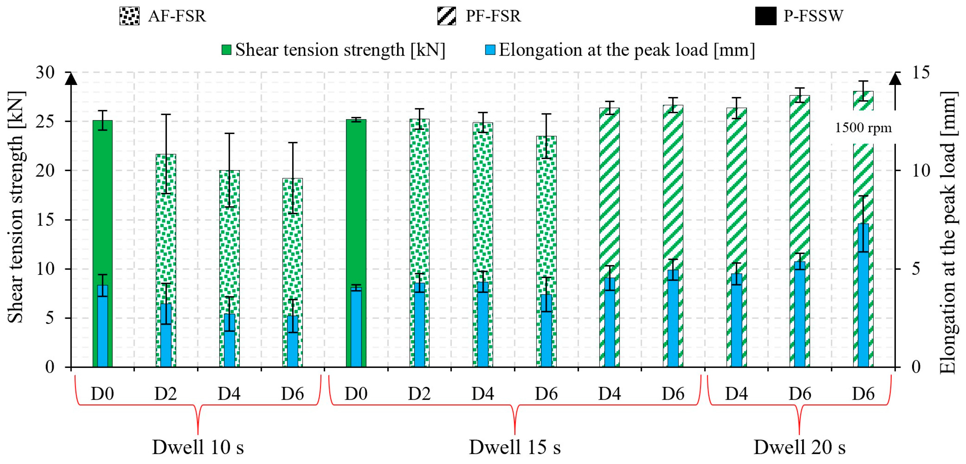
Figure 12 shows the shear tension strength, elongation at the peak load values, and the relative variability for the tested samples obtained with the trials outlined in Table 2. For the AF-FSR process, increasing the pre-hole diameter from 2 to 6 mm reduces the average shear tension strength from 22 to 19 kN. This decrease is attributed to the increasing difficulty in adequately filling larger pre-holes, resulting in voids that reduce the strength of the repaired part. The strength data show a wide variability of about 8 kN due to complex metal flow in the region between the upper and lower plates. The repairing processes might be highly sensitive to the extent and shape of the unwelded regions. Extending the dwell time to 15 s significantly reduces unwelded regions, leading to decreased variability in the strength data for samples with pre-hole diameters of 2 and 4 mm. However, at this dwell time, the 6 mm pre-hole remains too large to be effectively filled, resulting in wider data scattering.
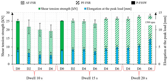
Figure 12.
Shear tension strength and elongation at the peak load results for the tested samples. If not specified, the tool rotational speed is 1000 rpm.
In the PF-FSR, the shear tension strength exceeded the values achieved via AF-FSR with the same dwell time (15 s) and pre-hole diameters (4 and 6 mm). Moreover, a lower variability of about 1.5 kN has been observed in all the PF-FSR repair conditions. This improvement is attributed to the metal filler, which plays a dual role: it helps fill the pre-hole by limiting the formation of unwelded regions and compensates for some of the material lost as flash during repair (i.e., an increase in the resistant section of the repaired area). Notably, the shear tension strength of the PF-FSR samples increases with the pre-hole diameter. This is due to the larger mixing area between the metal filler and the upper and lower plates that occurs with larger pre-hole diameters, as shown in Figure 7c and Figure 8b. The reference samples processed via P-FSSW (10 s dwell time) achieve a shear tension strength of approximately 25 kN with relatively low data variability. Therefore, reducing the partial filling of pre-holes strongly influences the mechanical performances of repaired regions.
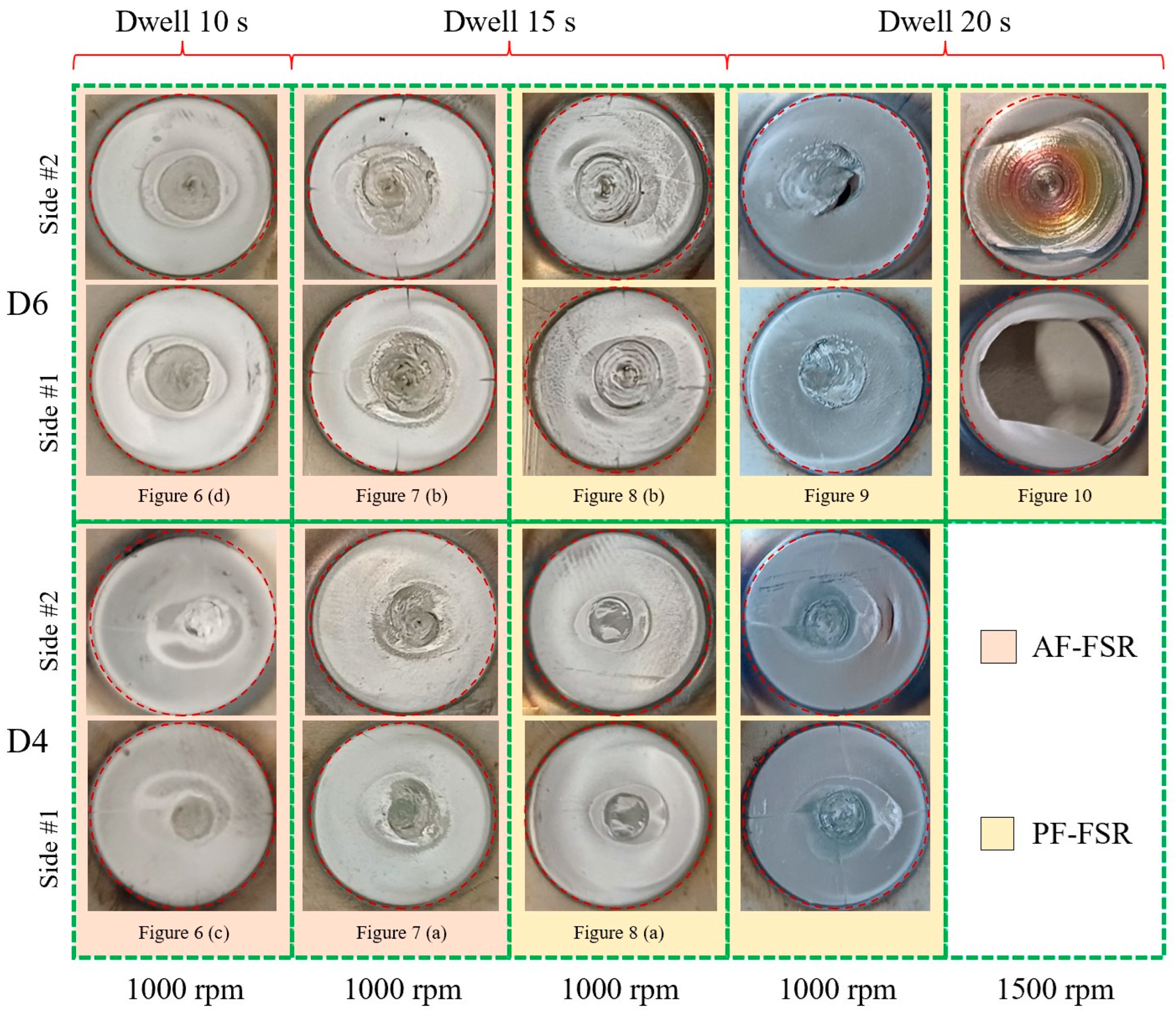
Figure 13 shows the fracture surfaces of the repaired sheet stacks obtained via AF-FSR and PF-FSR with pre-hole diameters of 4 and 6 mm. Under a 10 s dwell time and a rotational speed of 1000 rpm, the AF-FSR fracture surfaces exhibit interfacial failure caused by unrepaired regions in the middle of the pre-holes. At longer dwell times, the repaired regions reveal a combination of interfacial and partial-thickness fractures, with partial-thickness fractures becoming more prominent as the severity of the mixing process increases. In contrast, the PF-FSR process results in fracture surfaces predominantly through the thickness of the repaired regions, mainly due to the minimal or absent unrepaired areas. This effect is most evident when the rotational speed is increased to 1500 rpm, leading to complete pull-out failure. The fracture path observed is influenced by the initial condition of the repaired samples. The sheet overlap increased the difficulty of establishing a strong connection at the lap interface. Consequently, the fracture path progressively shifted from the lap interface to the thickness of the sheet stack as heat and mixing actions intensified. In contrast, existing literature typically addresses the repair of a defect in a single plate. Most studies have highlighted fractures occurring along the contour of the repaired defect, which can also potentially affect the underlying part of the plate [10,13,20,21,22,33]. Finally, Sajed et al. [7] adopted the same sheet stack configuration used in this study but obtained complete pull-out failure thanks to the superior material flow generated when processing aluminum alloys with friction-stir-based approaches.
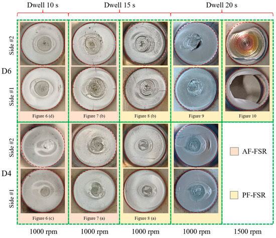
Figure 13.
Fracture surfaces of the repaired sheet stacks via AF-FSR and PF-FSR with pre-hole diameters of 4 and 6 mm.
4. Conclusions
This study evaluates the effectiveness of AF- and PF-FSR techniques for repairing AISI 304 stainless steel sheets. Overlapped 2 mm thick sheets with pre-drilled holes (2, 4, and 6 mm) were used to simulate a defect in a completely broken component. The key findings are summarized as follows:
- -
- PF-FSR demonstrated superior mechanical strength and consistency, particularly for 6 mm holes. Metal fillers in PF-FSR facilitated better defect filling and minimized voids, resulting in higher shear tension strength, exceeding 25 kN for larger holes, with lower data variability.
- -
- PF-FSR promoted efficient material mixing and filling of pre-holes, reducing unrepaired regions. Metal fillers enhanced mixing, ensuring a more homogeneous repair. AF-FSR struggled with larger holes, often leaving significant voids and reduced strength, especially in 6 mm holes, even with extended dwell times.
- -
- Parameters like rotational speed and dwell time significantly impacted repair quality. For PF-FSR, higher rotational speeds and dwell times generally improved pre-hole filling. However, excessive values caused deformation and flash formation. Rotational speeds up to 1500 rpm and dwell times up to 20 s ensured complete filling of larger holes but led to notable thinning and deformation. Thus, optimizing these parameters is crucial to balance effective repair and material integrity.
- -
- FSR of aluminum and magnesium alloys is well-documented, showing strong feasibility thanks to low vertical load and torque requirements, low tool wear rate, and good defect filling. FSR of austenitic stainless steels still presents significant challenges due to their low thermal conductivity and high strain hardening during plastic deformation.
The findings of this work underscore PF-FSR’s advantages in mechanical strength and repair quality of stainless steels, particularly for larger defects, and highlight the importance of optimizing process parameters for effective repairs.
Author Contributions
Conceptualization, P.R.S. and V.L.; methodology, P.R.S., V.L., V.R. and D.B.; formal analysis, P.R.S., V.L., V.R. and D.B.; investigation, P.R.S., V.L., V.R. and D.B.; experimental tests, V.L., V.R. and D.B.; writing—original draft preparation, P.R.S. and V.L.; writing—review and editing, P.R.S., V.L., V.R. and D.B.; supervision, P.R.S. All authors have read and agreed to the published version of the manuscript.
Funding
This research received no external funding.
Data Availability Statement
The raw data supporting the conclusions of this article will be made available by the authors on request.
Acknowledgments
This study was conducted at the Advanced Joining Technologies Laboratory J-Tech@PoliTO at Politecnico di Torino (http://www.j-tech.polito.it/, accessed on 4 July 2024). The authors would like to express their gratitude to eng. Gianmarco Rimmaudo for his valuable assistance to some laboratory experiments conducted during his student internship.
Conflicts of Interest
The authors declare no conflicts of interest.
References
- Jawahir, I.; Bradley, R. Technological Elements of Circular Economy and the Principles of 6R-Based Closed-loop Material Flow in Sustainable Manufacturing. Procedia CIRP 2016, 40, 103–108. [Google Scholar] [CrossRef]
- Duflou, J.; Seliger, G.; Kara, S.; Umeda, Y.; Ometto, A.; Willems, B. Efficiency and feasibility of product disassembly: A case-based study. CIRP Ann. 2008, 57, 583–600. [Google Scholar] [CrossRef]
- Saboori, A.; Aversa, A.; Marchese, G.; Biamino, S.; Lombardi, M.; Fino, P. Application of Directed Energy Deposition-Based Additive Manufacturing in Repair. Appl. Sci. 2019, 9, 3316. [Google Scholar] [CrossRef]
- Deng, L.; Niu, P.; Ke, L.; Liu, J.; Kang, J. Repairing of exit-hole in friction-stir-spot welded joints for 2024-T4 aluminum alloy by resistance welding. Int. J. Miner. Metall. Mater. 2023, 30, 660–669. [Google Scholar] [CrossRef]
- Lunetto, V.; De Maddis, M.; Russo Spena, P. Similar and dissimilar lap friction stir welding of titanium alloys: On the elimination of the hook defect. Int. J. Adv. Manuf. Technol. 2023, 126, 3417–3435. [Google Scholar] [CrossRef]
- Orlando, M.; De Maddis, M.; Razza, V.; Lunetto, V. Non-destructive detection and analysis of weld defects in dissimilar pulsed GMAW and FSW joints of aluminium castings and plates through 3D X-ray computed tomography. Int. J. Adv. Manuf. Technol. 2024, 132, 2957–2970. [Google Scholar] [CrossRef]
- Sajed, M. Parametric study of two-stage refilled friction stir spot welding. J. Manuf. Process. 2016, 24, 307–317. [Google Scholar] [CrossRef]
- Zhou, L.; Liu, D.; Nakata, K.; Tsumura, T.; Fujii, H.; Ikeuchi, K.; Michishita, Y.; Fujiya, Y.; Morimoto, M. New technique of self-refilling friction stir welding to repair keyhole. Sci. Technol. Weld. Join. 2012, 17, 649–655. [Google Scholar] [CrossRef]
- Qi, S.; Wen, Q.; Ji, S.; Meng, X.; Wu, B.; Qi, W. New technique of radial-additive friction stir repairing for exceeded tolerance holes. Int. J. Adv. Manuf. Technol. 2019, 105, 4761–4771. [Google Scholar] [CrossRef]
- Huang, R.; Ji, S.; Meng, X.; Li, Z. Drilling-filling friction stir repairing of AZ31B magnesium alloy. J. Mater. Process. Technol. 2018, 255, 765–772. [Google Scholar] [CrossRef]
- Niu, S.; Wu, B.; Ma, L.; Lv, Z.; Yan, D. Passive filling friction stir repairing AZ31-B magnesium alloy by external stationary shoulder. Int. J. Adv. Manuf. Technol. 2018, 97, 2461–2468. [Google Scholar] [CrossRef]
- Sajed, M.; Seyedkashi, S.H. Multilayer friction stir plug welding: A novel solid-state method to repair cracks and voids in thick aluminum plates. CIRP J. Manuf. Sci. Technol. 2020, 31, 467–477. [Google Scholar] [CrossRef]
- Ji, S.; Meng, X.; Huang, R.; Ma, L.; Gao, S. Microstructures and mechanical properties of 7N01-T4 aluminum alloy joints by active-passive filling friction stir repairing. Mater. Sci. Eng. A 2016, 664, 94–102. [Google Scholar] [CrossRef]
- Rao, H.; Jordon, J.; Boorgu, S.; Kang, H.; Yuan, W.; Su, X. Influence of the key-hole on fatigue life in friction stir linear welded aluminum to magnesium. Int. J. Fatigue 2017, 105, 16–26. [Google Scholar] [CrossRef]
- Wang, T.; Liu, T.; Roosendaal, T.; Upadhyay, P. Reinforcing the exit hole from friction stir welding and processing. Materialia 2022, 26, 101611. [Google Scholar] [CrossRef]
- Wen, Q.; Guo, R.; Song, Q.; Dong, Z.; Liu, G.; Huang, R.; Yang, K. Active-passive filling friction stir repairing of casting defects in ZL210 aluminum alloys. Int. J. Adv. Manuf. Technol. 2020, 106, 5307–5315. [Google Scholar] [CrossRef]
- Lv, Z.; Han, S.; Hu, W.; Dong, Z.; Huang, R.; Yang, K. Solid-State Repair of Casting Defects in ZL210 Aluminum Alloy. J. Mater. Eng. Perform. 2020, 29, 5886–5893. [Google Scholar] [CrossRef]
- Ji, S.; Huang, R.; Zhang, L.; Meng, X.; Lv, Z. Microstructure and Mechanical Properties of Friction Stir Repaired Al–Cu Casting Alloy. Trans. Indian Inst. Met. 2018, 71, 2057–2065. [Google Scholar] [CrossRef]
- Lattanzi, L.; Fabrizi, A.; Fortini, A.; Merlin, M.; Timelli, G. Effects of microstructure and casting defects on the fatigue behavior of the high-pressure die-cast AlSi9Cu3(Fe) alloy. Procedia Struct. Integr. 2017, 7, 505–512. [Google Scholar] [CrossRef]
- Ghavimi, A.; Aboutalebi, M.; Seyedein, S. Exit-hole repairing in friction stir welding of AA5456 pipe using consumable pin. Mater. Manuf. Process. 2020, 35, 1240–1250. [Google Scholar] [CrossRef]
- Han, B.; Huang, Y.; Lv, S.; Wan, L.; Feng, J.; Fu, G. AA7075 bit for repairing AA2219 keyhole by filling friction stir welding. Mater. Des. 2013, 51, 25–33. [Google Scholar] [CrossRef]
- Huang, Y.X.; Han, B.; Tian, Y.; Liu, H.J.; Lv, S.X.; Feng, J.C.; Leng, J.S.; Li, Y. New technique of filling friction stir welding. Sci. Technol. Weld. Join. 2011, 16, 497–501. [Google Scholar] [CrossRef]
- Meng, X.; Xie, Y.; Ma, X.; Liang, M.; Peng, X.; Han, S.; Kan, L.; Wang, X.; Chen, S.; Huang, Y. Towards Friction Stir Remanufacturing of High-Strength Aluminum Components. Acta Met. Sin. (Engl. Lett.) 2023, 36, 91–102. [Google Scholar] [CrossRef]
- Giuliodori, D.; Rodriguez, A. Analysis of the stainless steel market in the EU, China and US using co-integration and VECM. Resour. Policy 2015, 44, 12–24. [Google Scholar] [CrossRef]
- Deshmukh, D.D.; Kharche, Y. Influence of processing conditions on the tensile strength and failure pattern of resistance spot welded SS 316L sheet joint. Int. J. Interact. Des. Manuf. (IJIDeM) 2023, 1–13. [Google Scholar] [CrossRef]
- Li, H.; Jiang, Z.; Feng, H.; Zhang, S.; Li, L.; Han, P.; Misra, R.; Li, J. Microstructure, mechanical and corrosion properties of friction stir welded high nitrogen nickel-free austenitic stainless steel. Mater. Des. 2015, 84, 291–299. [Google Scholar] [CrossRef]
- Lunetto, V.; De Maddis, M.; Russo Spena, P. Pre-hole friction stir spot welding of dual-phase steels and comparison with resistance spot welding, conventional and pinless friction stir spot welding. Int. J. Adv. Manuf. Technol. 2023, 129, 2333–2349. [Google Scholar] [CrossRef]
- Yousefian, S.; Zarei-Hanzaki, A.; Barabi, A.; Abedi, H.; Moallemi, M.; Karjalainen, P. Microstructure, texture and mechanical properties of a nickel-free high nitrogen duplex stainless steel processed through friction stir spot welding. J. Mater. Res. Technol. 2021, 15, 6491–6505. [Google Scholar] [CrossRef]
- JIS Z 3136 Standard; Specimen Dimensions and Procedure for Shear Testing Resistance Spot and Embossed Projection Welded Joints. Japanese Standards Association: Tokyo, Japan, 2018.
- ASTM E112-13; Standard Test Methods for Determining Average Grain Size. ASTM International: West Conshohocken, PA, USA, 2021. [CrossRef]
- Mirandola, P.; Lunetto, V.; Novel, D.; Barozzi, M.; Bellutti, P.; De Maddis, M.; Russo Spena, P. Strength and microstructure of friction stir welded additively manufactured Scalmalloy® in as-welded and heat-treated conditions. J. Manuf. Process. 2023, 97, 1–11. [Google Scholar] [CrossRef]
- Jeon, J.; Mironov, S.; Sato, Y.; Kokawa, H.; Park, S.; Hirano, S. Friction stir spot welding of single-crystal austenitic stainless steel. Acta Mater. 2011, 59, 7439–7449. [Google Scholar] [CrossRef]
- Zhao, H.; Wang, Y.; Dong, J.; Wen, Q.; Gong, P.; Yue, Y. Eliminating Keyhole by Ultrasonic-Assisted Passive Filling Friction Stir Repairing Process. Trans. Indian Inst. Met. 2021, 74, 1501–1508. [Google Scholar] [CrossRef]


Disclaimer/Publisher’s Note: The statements, opinions and data contained in all publications are solely those of the individual author(s) and contributor(s) and not of MDPI and/or the editor(s). MDPI and/or the editor(s) disclaim responsibility for any injury to people or property resulting from any ideas, methods, instructions or products referred to in the content. |
© 2024 by the authors. Licensee MDPI, Basel, Switzerland. This article is an open access article distributed under the terms and conditions of the Creative Commons Attribution (CC BY) license (https://creativecommons.org/licenses/by/4.0/).