Article

Effect of Corrosion Environment on Mechanical Behavior of 5083/6005A Welded Joints

1
Hunan Engineering Research Center of Forming Technology and Damage Resistance Evaluation for High Efficiency Light Alloy Components, Hunan University of Science and Technology, Xiangtan 411201, China
2
Zhuzhou CRRC Times Electric Co., Ltd., Zhuzhou 412001, China
*
Authors to whom correspondence should be addressed.
Metals 2024, 14(8), 925; https://doi.org/10.3390/met14080925
Submission received: 12 July 2024 / Revised: 30 July 2024 / Accepted: 12 August 2024 / Published: 15 August 2024
(This article belongs to the Special Issue Forming and Properties of Lightweight Alloys)

Abstract

:
The corrosion fatigue behavior of welded joints is a critical concern in the transportation industry, which shortens their service life. In this paper, the corrosion damage of 5083/6005A welded joints exposed to different conditions (3.5% NaCl + 0.01 mol/L NaHSO3, 3.5% NaCl, 0.6 mol/L NaHSO3, and 3.5% NaCl + 0.01 mol/L NaHSO3-75 MPa) was investigated by using tensile and fatigue tests, polarization curves, scanning electron microscopy (SEM), and X-ray photoelectron spectroscopy (XPS). The findings indicate that elongation and fatigue life were most adversely affected by exposure to 3.5% NaCl + 0.01 mol/L NaHSO3-75 MPa. This was followed by the exposure to 3.5% NaCl + 0.01 mol/L NaHSO3, then 3.5% NaCl, with the mildest effects observed under 0.6 mol/L NaHSO3. The corrosion mechanisms were elucidated and the corrosion model was established through the analysis of corrosion morphologies and corrosion products. The corrosion fatigue fracture model was developed by analyzing the fracture surfaces. These findings provide references for preventing the corrosion-fatigue fractures of 5083/6005A welded joints, extending their service life, and enhancing the operational safety and reliability of trains.

1. Introduction

The 5083 and 6005A aluminum alloys, renowned for their lightweight, good formability, and excellent corrosion resistance properties, are widely used in manufacturing key components in high-speed trains, such as the body structures, electrical cabinets, and lifting lugs [1,2]. In actual operation, these key components of high-speed trains have to withstand complex dynamic loads from high-frequency vibrations and periodic stresses, but also face challenges from varying climates and humid environments, especially in heavy industrial or coastal areas [3]. These environmental factors can exacerbate the corrosion risk of aluminum alloys, leading to premature fractures caused by corrosion fatigue damage [4]. Consequently, the damage behavior of aluminum alloys in different environments, especially corrosive ones, has garnered extensive attention from scholars in recent years [5,6,7].
Corrosive environments mainly consist of Cl and SO42− ions, which can rupture the protective oxide film on aluminum alloy surfaces, leading to corrosion [8,9,10]. Cl ions have a small ionic radius and high charge density, enabling them to penetrate and damage the protective oxide films on aluminum alloy surfaces [11]. SO42− ions are strongly adsorptive and competes with OH to adsorb on the oxide film, hindering the formation of oxide film [12]. Therefore, both types of ions can severely corrode aluminum alloys, significantly reducing their mechanical properties. Yadav et al. [13] demonstrated that the fatigue life of 2024 aluminum alloy weld joints is reduced by 6 times in the 3.5% NaCl corrosive medium compared to an air environment, which is attributed to the pitting action of Cl ions. Ge et al. [14] investigated the mechanical properties of 7075 aluminum alloys after exposure to the 3.5% NaCl solution with different NaHSO3 concentrations. They found that tensile strength and elongation decrease as NaHSO3 concentration increases, which is attributed to the reduction in pH caused by higher NaHSO3 concentrations, thereby accelerating the corrosion rate [15]. Additionally, the hydrogen is proposed to diffuse into the material and embrittle the crack tip, promoting hydrogen-induced cracking (HIC) [16]. Oger et al. [17] studied the stress corrosion cracking (SCC) sensitivity of 7046 aluminum alloy, indicating that the hydrogen in 7046 aluminum alloy leads to brittle transgranular and intergranular fractures.
It is widely recognized that fatigue corrosion in aluminum alloys frequently occurs at the joints between components [18,19]. In high-speed trains, welding is the preferred method for forming these joints, owing to its cost-effectiveness and efficiency [20]. The intense heat of welding alters the microstructure of aluminum alloys, such as grain growth, precipitate dissolution, and precipitate coarsening at the heat-affected zone (HAZ), which diminishes the corrosion resistance of the welded joints [21]. Bocchi et al. [22] indicated that coarse intermetallic compounds and fine intergranular S-phase precipitates in the HAZ render it vulnerable to pitting and intergranular corrosion, causing the HAZ of the 2024 aluminum alloy welded joint to be more prone to corrosion than the base material. The corrosion resistance in welded joints further deteriorates when composed of dissimilar materials [23]. Davoodi et al. [24] revealed that the local relative potential difference of 700 mV between 7023 and 5083 aluminum alloy in 5083/7023 welded joints leads to galvanic corrosion, thereby accelerating joint degradation.
From the above discussion, aluminum alloys and their welded joints are susceptible to corrosion fatigue in corrosive environments, significantly reducing their fatigue life and leading to the premature failure of aluminum alloy components. Investigating the impact of corrosion on the mechanical behavior of 5083/6005A welded joints is crucial for predicting their operational reliability and ensuring the safety of high-speed trains. However, the corresponding corrosion studies in aluminum alloy welded joints were incomprehensive and incomplete. To elucidate the effects of corrosion on the mechanical properties of 5083/6005A welded joints, the impacts of different corrosion conditions (3.5% NaCl + 0.01 mol/L NaHSO3, 3.5% NaCl, 0.6 mol/L NaHSO3, and 3.5% NaCl + 0.01 mol/L NaHSO3-75 MPa) on the tensile and fatigue properties of 5083/6005A welded joints were studied for the first time. The corrosion model and fracture model were established by analyzing the corrosion morphology, the fracture surfaces, and corrosion products of 5083/6005A welded joints. And, then, the corrosion mechanisms for Cl and SO42− were elucidated in detail. This study is motivated by the need to enhance the reliability and safety of high-speed trains, which frequently operate in coastal and industrial regions where such corrosive conditions are prevalent.

2. Experimental

2.1. Material

The welding joint materials consisted of 6.0 mm-thick 5083-H111, 6005A-T6 plates, and φ3.5 mm ER5356 welding wire. The welding was performed using a Fronius TPS4000 (Fronius, Wels, Austria) MIG welding machine with 12 L/min of argon gas, oriented perpendicularly to the rolling direction of plates. The chemical composition of 5083/6005A welding joint was determined using a SPECTRO BLUE SOP (SPECTRO, Kleve, Germany) inductively coupled plasma optical emission spectrometer, as shown in Table 1.

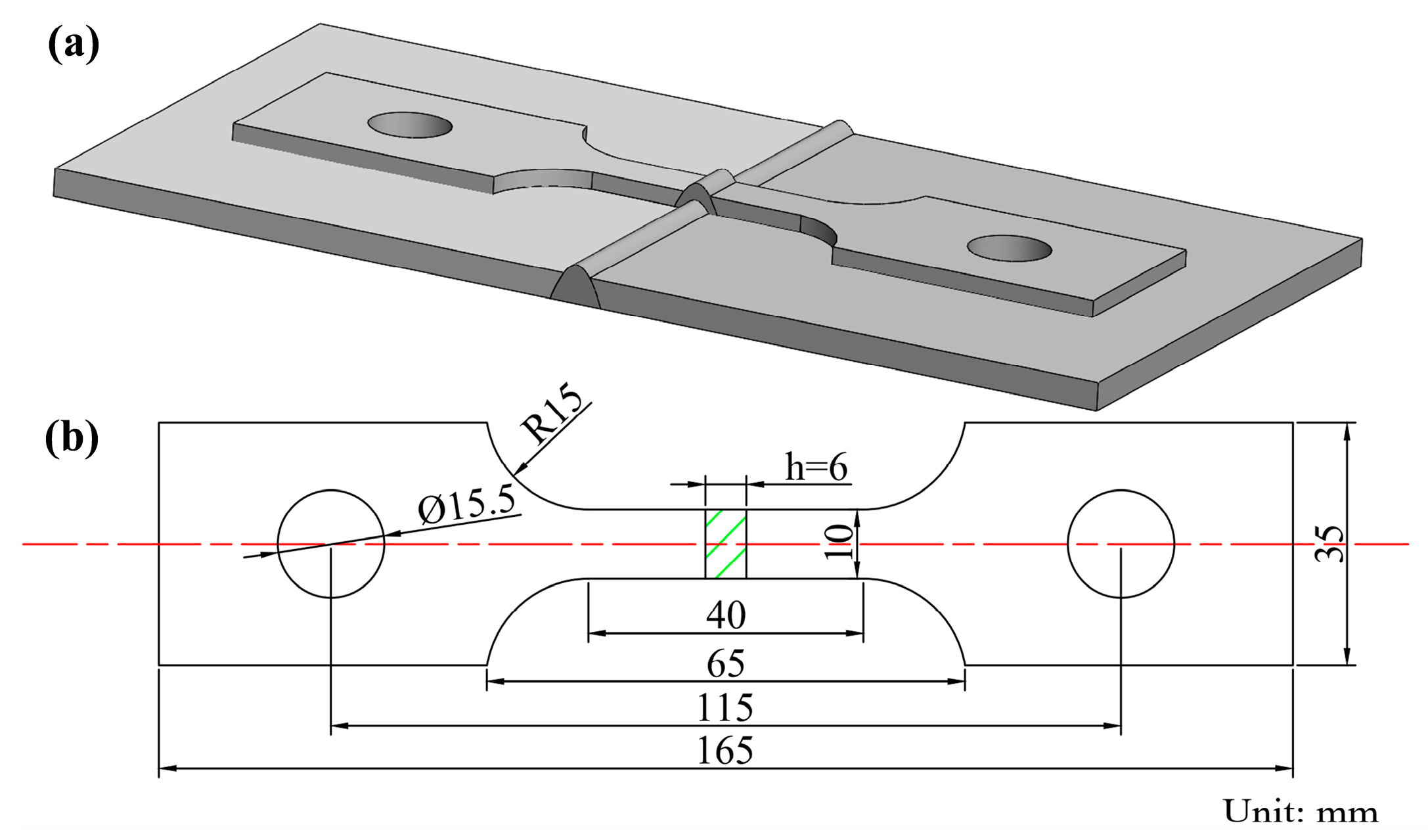
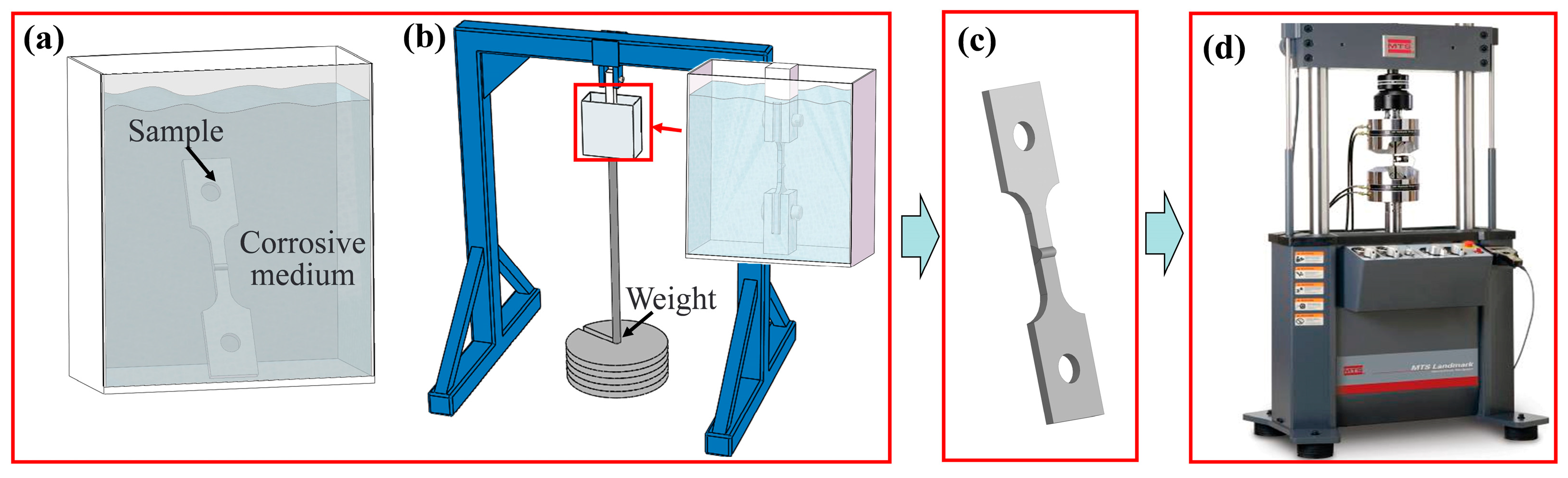
2.2. Corrosion, Tensile, and Fatigue Test

Experimental samples for corrosion, tensile, and fatigue testing were prepared with a parallel section measuring 40 mm in length, 10 mm in width, and 6 mm in thickness, as shown in Figure 1. Considering the actual dimensions of the specimen, the corrosion environment chamber and other experimental apparatus were designed based on GB/T20120.1-2006 [25]. The corrosion test apparatus and the stress corrosion test apparatus are shown in Figure 2a,b. The corrosive media included 3.5% NaCl + 0.01 mol/L NaHSO3 (A condition), 3.5% NaCl (B condition), and 0.6 mol/L NaHSO3 (C condition). The stress corrosion test used 3.5% NaCl + 0.01 mol/L NaHSO3 medium with 75 MPa (D condition). The exposure time of corrosion test was 7 days.
To study the tensile and fatigue properties of 5083/6005A welded joints after corrosion, the tensile tests and fatigue tests were performed based on the ASTM E8 and HB 5287-96 standard [26,27], as shown in Figure 2d. The mechanical tensile rate was 2 mm/min. The fatigue maximum stress (σmax), loading frequency (f), and stress ratio R (σminmax) were 100 MPa, 75 Hz, and 0.1, respectively.

2.3. Electrochemical Experiment

The electrochemical testing of 5083/6005A weld joint was conducted using a CHI760E (CH Instruments, Austin, TX, USA) electrochemical workstation. Based on the GB/T 24196-2009 standard [28], the three-electrode system was used for testing. The 5083/6005A weld joint, the saturated calomel electrode (SCE), and the platinum electrode served as the working electrode, the reference electrode, and the counter electrode, respectively. The polarization curve testing was conducted with the scan range from −1.2 V to −0.3 V and the scan rate of 0.5 mV/s.

2.4. Microstructural Characterization

The 5083/6005A weld joints were first cleaned for 300 s using an ultrasonic cleaner with an alcohol solution at a frequency of 40 Hz to ensure the removal of any surface contaminants. Following this preparation, the samples were observed using a CIQTEK SEM5000 (CIQTEK, Hefei, China) scanning electron microscope (SEM) operating in secondary electron mode with a working voltage of 25 kV.

2.5. X-ray Photoelectron Spectroscopy (XPS)

XPS tests were conducted on the corroded 5083/6005A weld joints using an ESCALAB 250Xi (Thermo Fisher Scientific, Waltham, MA, USA) X-ray photoelectron spectrometer. The excitation source was monochromatic Al Kα radiation, covering a detection area of 5 × 5 mm2. The XPS experimental parameters were set as follows: X-ray power of 150 W (voltage 15 kV, current 10 mA); pass energy of 160 eV for survey scans with the step size of 1.0 eV; and pass energy of 40 eV for high-resolution scans with a step size of 0.1 eV. Data analysis was performed using Avantage software (version 5.99).

3. Results

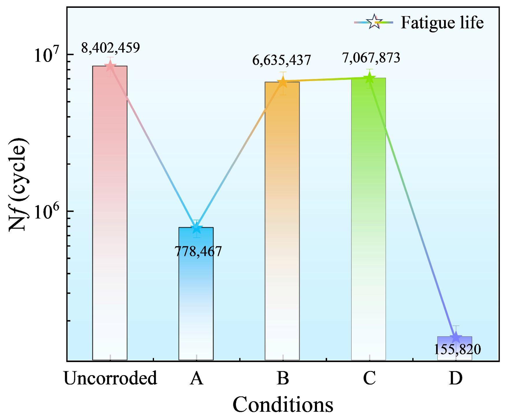
3.1. Mechanical Properties

After corrosion at various conditions, the mechanical properties and stress–strain curves of 5083/6005A weld joints are shown in Figure 3. The tensile strength of uncorroded 5083/6005A weld joints was 205 MPa, with the elongation of 11.3%. After exposure to Solution A, the tensile strength of the 5083/6005A weld joints remained unchanged, but their elongation decreased to 9.0%. These results indicate that corrosion can significantly affect elongation of the 5083/6005A weld joints. When the corrosive medium was changed to B and C, the elongations of 5083/6005A weld joints were 9.6% and 10.1%, respectively, while the tensile strength were essentially consistent (206 MPa and 210 MPa). The results show that the impact of a corrosive medium on the elongation of 5083/6005A welded joints ranks from greatest to least as A, B, and C. To further investigate the performance changes of 5083/6005A welded joints under the synergistic effects of corrosion and stress, the A corrosion medium was chosen for the corrosion test with enduring 75 MPa because it has the most significant impact on these samples. In the D stress corrosion condition, the tensile strength and elongation of 5083/6005A weld joints decreased to 180 MPa and 7.6%, respectively, indicating that enduring stress significantly accelerates the corrosion rate during the corrosion process.
The fatigue life of 5083/6005A weld joints after corrosion at various conditions is shown in Figure 4. In the A corrosive medium, the fatigue life of 5083/6005A weld joints decreased by 90.7%. When the corrosive medium changed to B and C, the fatigue life of the 5083/6005A weld joints slightly decreased, dropping by 21.1% and 15.9%, respectively. This indicates that the impact of the corrosive medium on the fatigue life of 5083/6005A welded joints ranks from greatest to least as A, B, and C. In the D stress corrosion condition, the fatigue life of the 5083/6005A weld joints decreased by 98.1%, which also indicates that enduring stress significantly accelerates the corrosion rate during the corrosion process.

3.2. Microstructural Morphology

3.2.1. Corrosion Morphology

The corrosion morphologies of 5083/6005A weld joints after exposure to various conditions are shown in Figure 5. In the A corrosive medium, the HAZ surfaces of both base materials exhibited numerous corrosion pits, with some pits covered by corrosion products, as shown in Figure 5a,e. In the B corrosive medium, the corrosion morphology of both base materials was similar to those samples exposed to the A corrosive medium, but the corrosion pits were shallower and covered with fewer corrosion products, as shown in Figure 5b,f. In the C corrosive medium, the surface of both base materials lacked observable corrosion pits, with numerous corrosion products, as shown in Figure 5c,g. The results indicate that the impact of the corrosive medium on the corrosion damage of 5083/6005A welded joints ranks from greatest to least as A, B, and C. In the D stress corrosion condition, the corrosion damage in the HAZ of both base materials became more prominent, as evidenced by numerous corrosion pits coalescing to form larger pits, and were covered with more corrosion products, as shown in Figure 5d,h. Notably, the corrosion damage in the HAZ of the 5083 base material was less severe than that in the 6005A base material under conditions A, B, and C, but more severe under condition D.

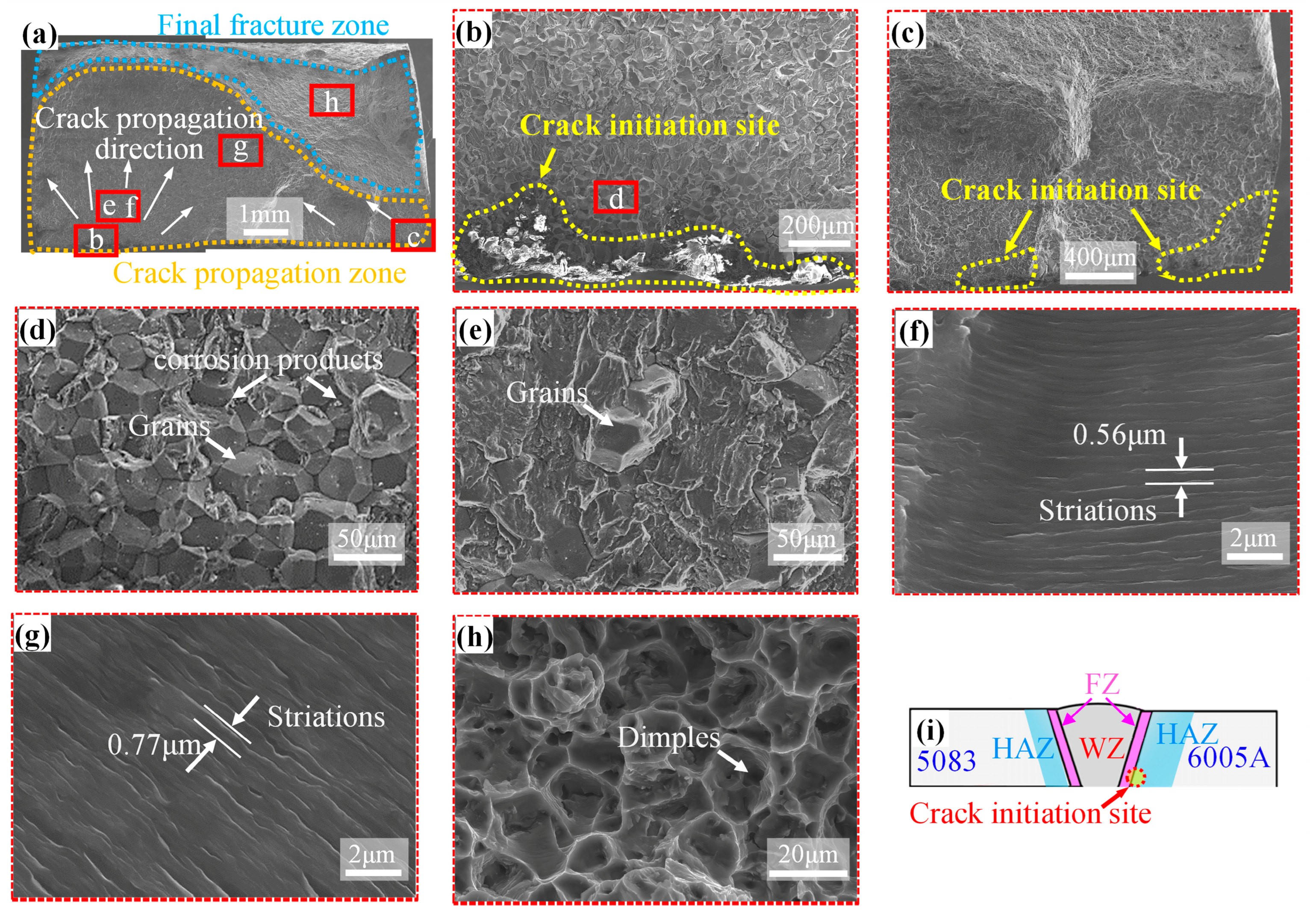
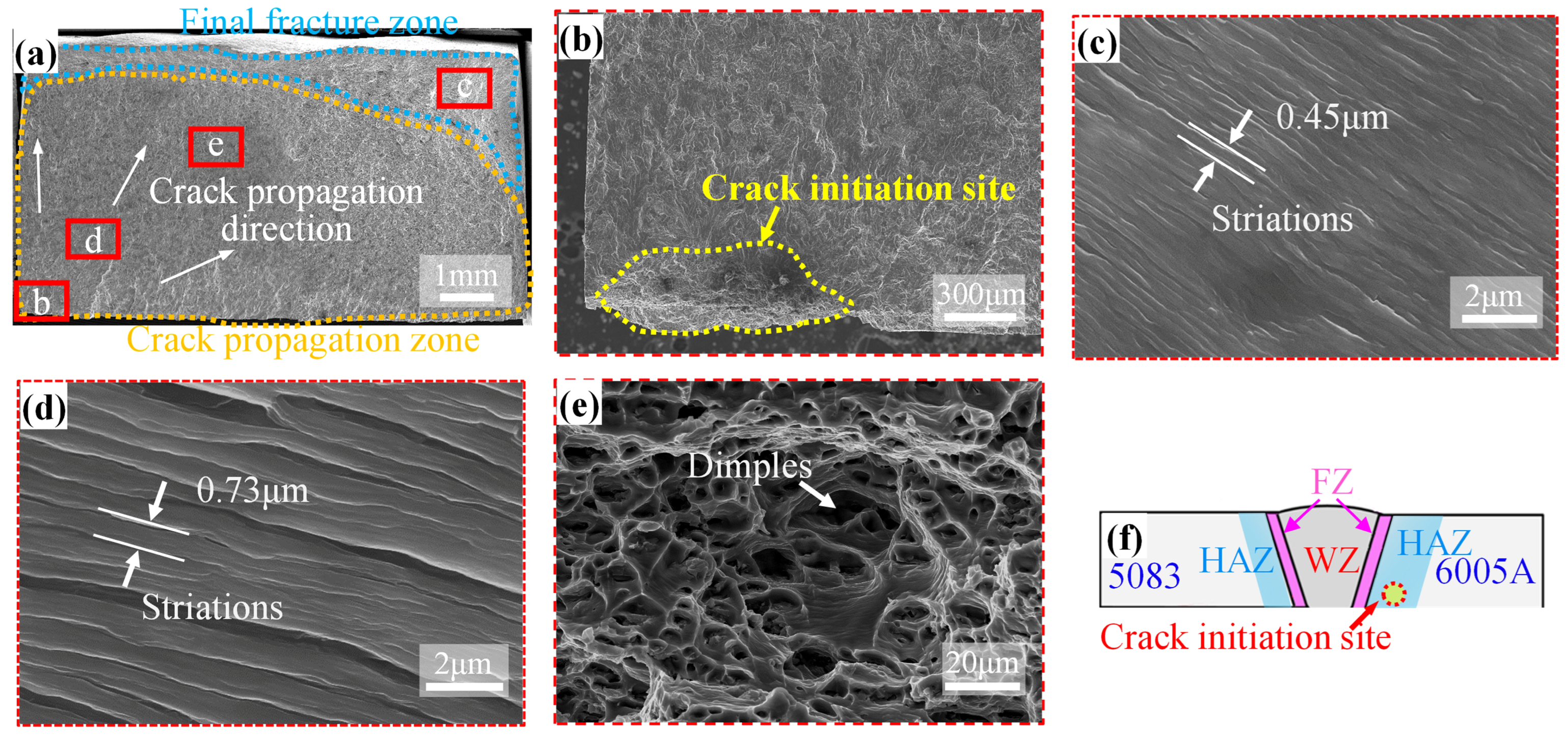
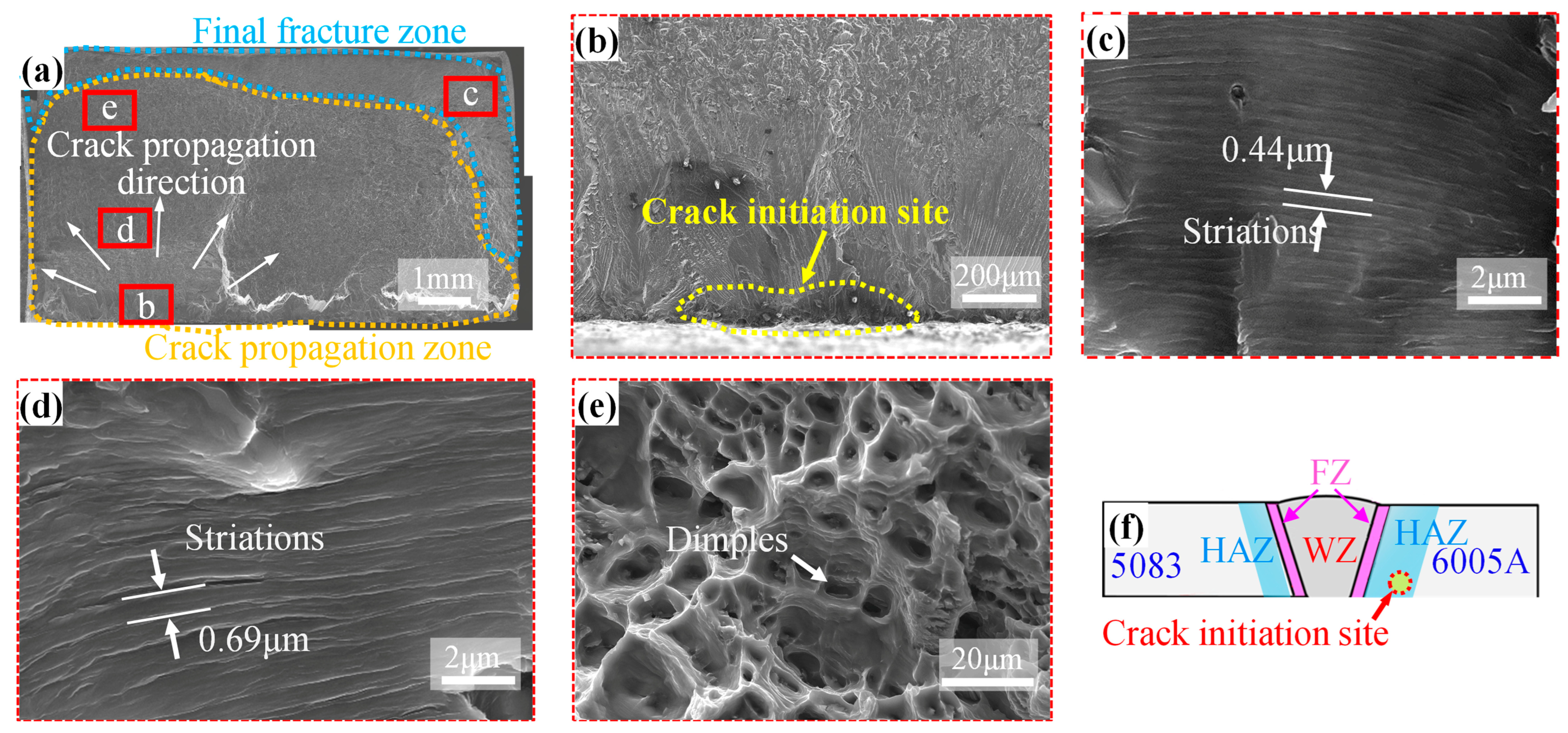
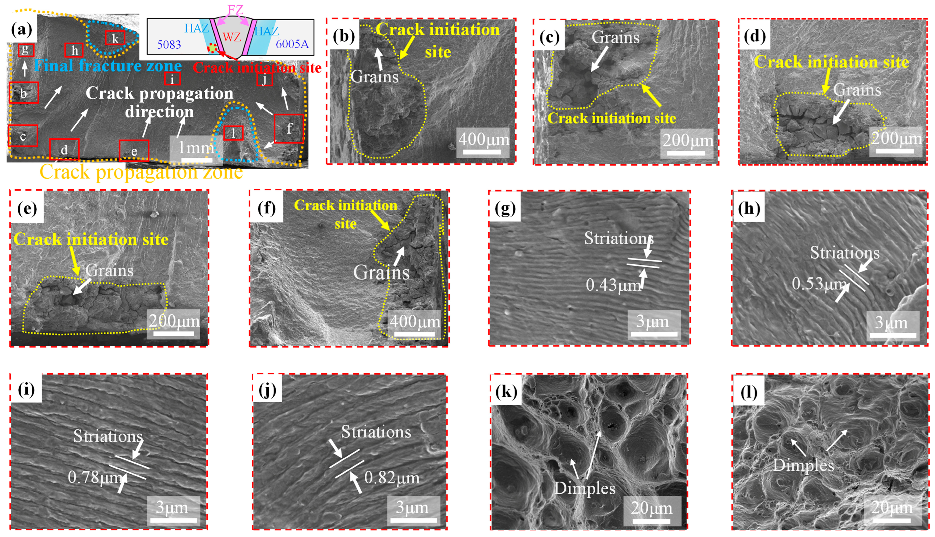
3.2.2. Fracture Morphology

The tensile fracture morphologies of 5083/6005A weld joints after corrosion under various conditions are shown in Figure 6. The fracture morphology of uncorroded 5083/6005A weld joints exhibited numerous dimples on the surface, accompanied by the obvious necking phenomenon, as shown in Figure 6(a1,a2). After exposure to the A and B corrosive media, the smaller dimples were observed on the surface and the fracture surface area was increased, as shown in Figure 6(b1,b2,c1,c2). However, the fracture morphology was similar to the uncorroded joints after exposure to the C corrosive medium, as shown in Figure 6(d1,d2). This indicates that the C corrosive medium causes minor corrosion damage to 5083/6005A welded joints. In the D stress corrosion condition, the fracture surface of the joints was relatively flat, characterized by shallow dimples scattered across the surface and corrosion pits clearly visible at the edges, as shown in Figure 6(e1,e2). The plasticity of aluminum alloy is decreased by smaller and shallower dimples [29], which suggests that corrosion can significantly reduce the plasticity of 5083/6005A weld joints, thereby decreasing their elongation.
Figure 7, Figure 8, Figure 9 and Figure 10 show the fatigue fractures of 5083/6005A weld joints corroded at different conditions. The 5083/6005A weld joints fractured at the HAZ on the 6005A side during fatigue tests when corroded without enduring stress (Figure 7i, Figure 8f and Figure 9f).
In the A corrosion medium, three crack initiation sites were observed on the fatigue fracture surface of 5083/6005A weld joints, as shown in Figure 7a–c. The dominant crack initiation site was covered with many corrosion products (Figure 7b) and displayed evident intergranular fracture (Figure 7d). This intergranular fracture gradually transformed into a transgranular fracture with increasing distance from the crack initiation site (Figure 7e). In the crack propagation zone, the fatigue striation spacing near the crack initiation zone was 0.56 μm and near the final fracture zone was 0.77 μm, as depicted in Figure 7f,g. For the final fracture zone, the numerous dimples were observed on the fatigue fracture surface, as shown in Figure 7h.
The fatigue fracture morphologies of 5083/6005A weld joints exposed to B and C corrosion media were similar, each exhibiting only one crack initiation site, as shown in Figure 8a and Figure 9a. These crack initiation sites demonstrated slight corrosion damage, which was markedly more pronounced in the B corrosive medium, as depicted in Figure 8b and Figure 9b. In the crack propagation zone, fatigue striations were observed on the fracture surfaces under both conditions. The spacings of these fatigue striations near the crack initiation zones in the B and C conditions were 0.45 μm and 0.44 μm, respectively, while the spacings were 0.73 μm and 0.69 μm near the final fracture zone, as shown in Figure 8c,d and Figure 9c,d. In the final fracture zone, the dimples were observed on fracture surfaces under both conditions, and their morphologies were similar, as shown in Figure 8e and Figure 9e.
In the D stress corrosion condition, the 5083/6005A weld joints fractured in the HAZ on the 5083 side, and their fatigue fracture surface had five crack initiation sites, as shown in Figure 10a. Many grains were observed at the crack initiation site due to corrosion damage, as shown in Figure 10b–f. In the crack propagation zone, two crack propagation directions were observed: some cracks radially propagated from the initiation site when there is an absence of other nearby cracks, while other cracks propagated unidirectionally along the direction of maximum stress intensity at the crack tip influenced by nearby cracks. Additionally, different regions of the crack propagation zone exhibited varying propagation rates, as evidenced by the fact that the fatigue striation spacings on the left side were 0.43 μm and 0.53 μm (Figure 10g,h), versus 0.87 μm and 0.92 μm on the right side (Figure 10i,j). More crack initiation sites were observed on the left side of the fracture, resulting in less force being applied to each individual crack tip. Consequently, the crack propagation rate was higher on the right side of the fracture. Two final fracture zones were observed in the fatigue fracture on the upper and lower sides, each with numerous dimples, as shown in Figure 10k,l.

3.3. Corrosion Behavior

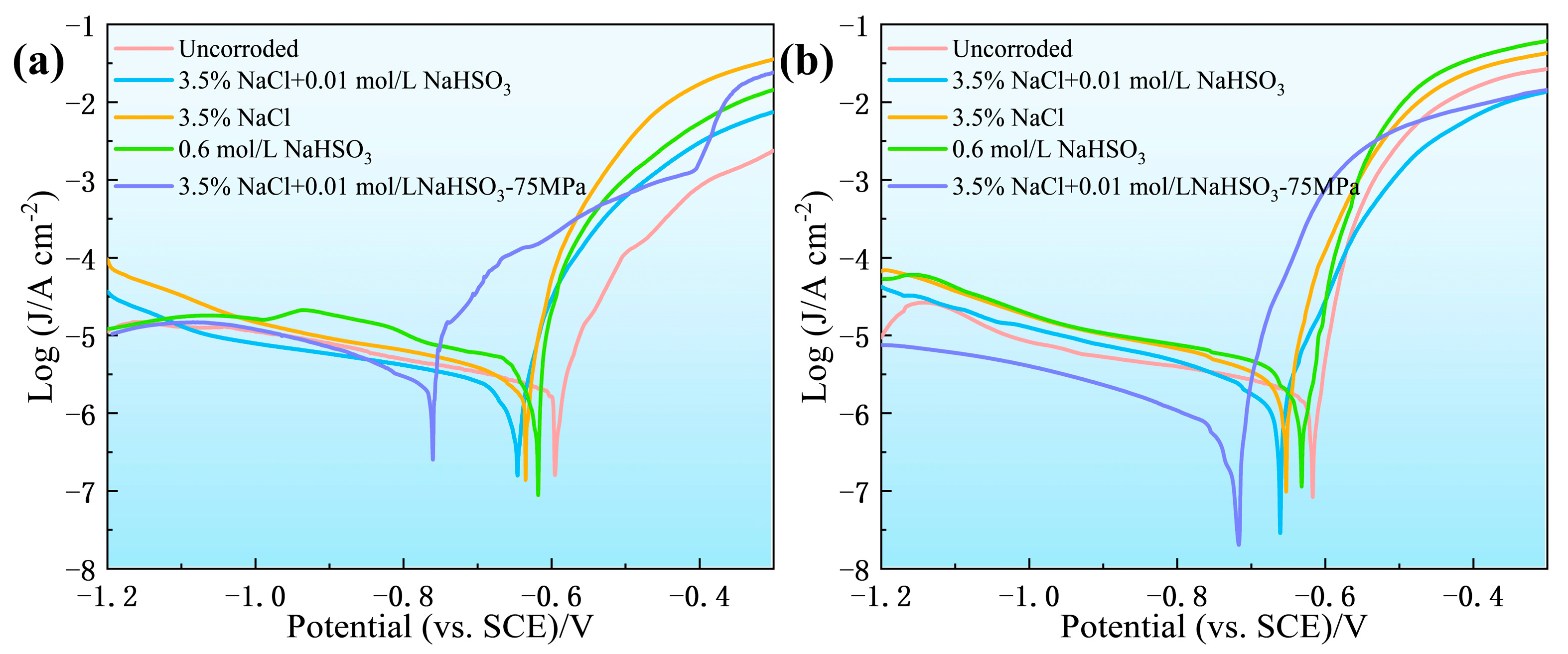
3.3.1. Polarization Curves

Figure 11 shows the polarization curves of 5083/6005A weld joints exposed to different conditions. The polarization parameters were calculated using the Tafel extrapolation method, as shown in Table 2. The corrosion potential (Ecorr) of both base materials decreased after exposure to different conditions, while the corrosion current density (Jcorr) increased, which suggests that the corrosion tendency and rate are increasing. After exposure to A, B, and C corrosion media, the Ecorr of 5083 base materials decreased by 9.4%, 6.2%, and 4.5%, respectively, while the Jcorr increased by 100%, 125%, and 209%. For the 6005A base materials, the Ecorr decreased by 7.5%, 6.0%, and 2.6%, respectively, and the Jcorr increased by 28%, 19%, and 119%. The results indicate that the impact of the corrosive medium on the corrosion resistance of 5083/6005A welded joints ranks from greatest to least as A, B, and C. After stress corrosion in the D condition, the Ecorr and Jcorr of 5083 base materials decreased by 17.2% and 44%, respectively, and decreased by 9.0% and 68% in the 6005A base materials, which indicates that stress corrosion significantly reduces the corrosion resistance of 5083/6005A weld joints. Additionally, the decrease in Jcorr is attributed to the rapid corrosion rate during stress corrosion, where most of the secondary phases in 5083/6005A weld joints were corroded or detached, thereby affecting the Jcorr measured in the polarization curve tests.

3.3.2. Chemical Composition of Corrosion Products

Figure 12 shows the XPS analysis results of 5083/6005A weld joints after exposure to different media. After exposure to the A corrosion medium, the XPS survey spectrum shows that the surface corrosion products of 5083 and 6005A base materials primarily contained Mg, O, C, Cl, and Al elements (Figure 12(a1)). Notably, the S element was not observed on the surface of 5083 and 6005A base materials due to the low content of NaHSO3 in the corrosion medium. The XPS spectra for Al2p of 5083 and 6005A base materials both display three peaks. The binding energies of these peaks at 75.7, 74.5, and 73.9 eV can be assigned to AlCl3, Al2O3, and Al(OH)3 [30,31], as shown in Figure 12(a2,a3). These peak area ratios were 11.9%, 59.4%, and 28.7% in the5083 base materials, respectively, while they were 29.9%, 50.2%, and 20.9% in the 6005A base materials.
After exposure to the B corrosion medium, the surface corrosion products of 5083 and 6005A base materials were essentially the same as those exposed to the A corrosion medium, as shown in Figure 12(b1). The XPS spectra for Al2p of 5083 base materials displayed four peaks at binding energies of 75.7 eV for AlCl3, 74.5 eV for Al2O3, 73.9 eV for Al(OH)3, and 73.0 eV for Al [30,31,32], with peak area ratios of 24.3%, 42.0%, 22.0%, and 11.7%, respectively, as shown in Figure 12(b2). In contrast, the 6005A base materials displayed three peaks (excluding Al peak), with peak area ratios of 28%, 51.6%, and 20.4%, respectively, as shown in Figure 12(b3).
After exposure to the C corrosion medium, the XPS survey spectrum shows that the surface corrosion products of the 5083 and 6005A base materials primarily contained Mg, Na, O, C, S, and Al elements (Figure 12(c1)). The Al2p spectra of both base materials in 5083/6005A weld joints displayed four peaks at binding energies of 74.9 eV for Al2(SO4)3, 74.5 eV for Al2O3, 73.9 eV for Al(OH)3, and 73.0 eV for Al [8,30,31,32], as illustrated in Figure 12(c2,c3). The peak area ratios of these corrosion products in 5083 base materials were 37.1%, 37.3%, 19.5%, and 6.1%, respectively, while the ratios were 37.1%, 38.6%, 17.2%, and 7.1% in the 6005A base materials.
From the above analysis, corrosion products of 5083/6005A weld joints in A and B corrosion media primarily consist of Al(OH)3, Al2O3, and AlCl3, while, in the C corrosion medium, they consist of Al(OH)3, Al2O3, and Al2(SO4)3.

4. Discussion

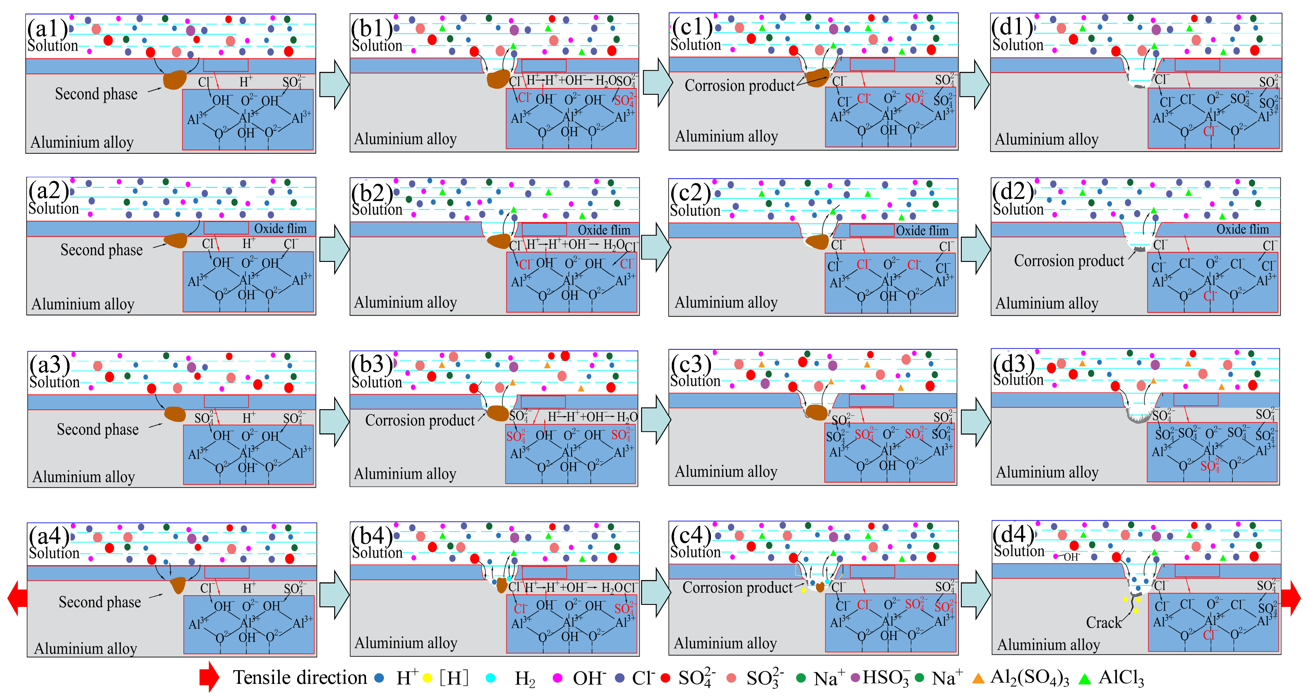
4.1. Corrosion Mechanism of 5083/6005A Welded Joints

The dense oxide film on aluminum alloy surfaces endows them with excellent corrosion resistance, consisting of oxides and hydroxides [33]. In corrosive environments, these oxide film surfaces have the positive charge and are prone to adsorbing corrosive ions (Cl and SO42−) due to the coulombic interactions, which reduce their surface energy [34]. Then, some of these corrosive ions penetrate the oxide film to reach the metal interface, causing the oxide film to rupture [35,36], especially in cases where defective oxide films are formed in the presence of secondary phase particles [37]. After the oxide film is ruptured, the secondary phase particles form micro-galvanic cells with the adjacent aluminum matrix due to their potential difference, leading to galvanic corrosion and the formation of corrosion pits, as shown in Figure 5. These corrosion processes occur through a series of reactions (1)–(8), with the anodic (Equation (1)) and cathodic (Equation (2)) reactions occurring first, as presented below [38]:
Al 3 e Al 3 +
O 2 + 2 H 2 O + 4 e 4 OH -
As the result of cathodic reactions, the concentration of OH ions increases, and the following reaction occurs:
Al 3 + + 3 OH Al ( OH ) 3
Then, Al(OH)3 further transforms into Al2O3 by reaction (4):
2 Al ( OH ) 3 Al 2 O 3 + 3 H 2 O
When HSO3 ions are present in the environment, they have dual effects on the corrosion of aluminum alloys [14]: disrupting the oxide film and acidifying the solution. The HSO3 acidifies the solution via the following reactions (5) and (6):
HSO 3 H + + SO 3 2 -
2 SO 3 2 - + O 2 2 SO 4 2 -
As the concentration of Al(OH)3 increases, Cl and SO42− ions participate in the reaction due to their adsorption on the oxide film surface, which leads to the disruption of the oxide film and the formation of stable compounds (AlCl3 and Al2(SO4)3) via the reactions (7) and (8) [7]:
Al ( OH ) 3 + 3 Cl - AlCl 3 + 3 OH -
6 H + + 3 SO 4 2 - + 2 Al ( OH ) 3 Al 2 ( SO 4 ) 3 + 6 H 2 O
Therefore, the corrosion products formed on 5083/6005A welded joints in different corrosion media generally consist of Al(OH)3, Al2O3, AlCl3, and Al2(SO4)3, as identified in the XPS results (Figure 12).
According to Equation (5), H+ is generated with the ionization of HSO3 in A and C corrosion media, which decreases the pH of the solution and accelerates the corrosion rate [39]. Zhang [15] also observed similar results. However, Blücher et al. [40] suggested that sulfate inhibits the chloride-induced pitting of aluminum. These differences can be partly attributed to the influence of the concentration of the corrosion products. While all aluminum chlorides are soluble in water, the solubility of the corresponding sulfates is much lower [14]. Our results indicate that the high concentration of corrosion product Al2(SO4)3 easily deposits on the aluminum alloy surface under high concentrations of HSO3 (C condition), which prevents direct contact between SO42− ions and the aluminum alloy matrix, thereby hindering further corrosion [41]. In contrast, the formation of corrosion product Al2(SO4)3 is minimal under low concentrations of HSO3 (A condition), which accelerates the corrosion rate due to the reduction in pH. Therefore, the impact of the corrosive medium on th ecorrosion damage of 5083/6005A welded joints ranks from greatest to least as A, B, and C, as shown in Figure 5b–d.
The HIC dominates the stress corrosion process, rather than anodic dissolution. Stannard et al. [42] indicated that the hydrogen is generated with the dissolution of Mg-rich particles during stress corrosion. With the evolution of H+, some H+ ions may permeate into the matrix to form hydrogen atoms [43], which embrittle the material [44], as described by reaction (9). Therefore, the corrosion damage of 5083/6005A welded joints is more severe in the D stress corrosion condition.
H + + e H
Based on the above analysis and experimental results, the corrosion mechanism diagrams for 5083/6005A welded joints in different conditions have been established, as shown in Figure 13. In the initial stages of corrosion, Cl or SO42− adsorb on the oxide film of 5083/6005A welded joints, and the defective oxide film near the secondary phase is rapidly disrupted due to the influence of Cl and SO42−, as shown in Figure 13(a1–a4). In the pitting stage, the corrosion processes in different corrosion media exhibit significant differences, which are related to the types of secondary phases and the presence of enduring stress [45]. Mg2Si is the primary secondary phase in the 5083 base material, while Al(Fe, Mn)Si is mainly found in the 6005A base material [46]. These secondary phases form micro-galvanic cells with the matrix during the corrosion process, where Mg2Si serves as the anode and corrodes, and Al(Fe, Mn)Si serves as the cathode [47]. Moreover, stress corrosion promotes the dissolution of the Mg-rich phase [42].
For non-stress corrosion (A, B, and C condition), the aluminum alloy matrix near the Al(Fe, Mn)Si phase is gradually corroded in the pitting stage, as shown in Figure 13(b1–b3). As the corrosion intensifies, the matrix further corrodes, and the OH in the oxide film is progressively replaced by Cl and SO42−, as shown in Figure 13(c1–c3). In the corrosion pit expansion stage, the matrix around the Al(Fe, Mn)Si phase is completely corroded, causing the secondary phase to detach, as shown in Figure 13(d1–d3). Among them, few corrosion products deposit on the corrosion pit in the A and B corrosion media, while many corrosion products deposits on the corrosion pit in the C medium.
For stress corrosion (D condition), H2 and H+ are generated in the pitting stage due to the dissolution of the Mg2Si phase, which acidifies the corrosion pit interior and significantly accelerates the corrosion rate, as shown in Figure 13(b4). In the corrosion pit expansion stage, the Mg2Si phase is almost completely corroded, and the H+ permeate into the matrix to form hydrogen atoms, which leads to hydrogen embrittlement, as illustrated in Figure 13(c4). With the Mg2Si phase dissolving completely, the corrosion pit interior forms micro-cracks due to enduring stress, as shown in Figure 13(d4).

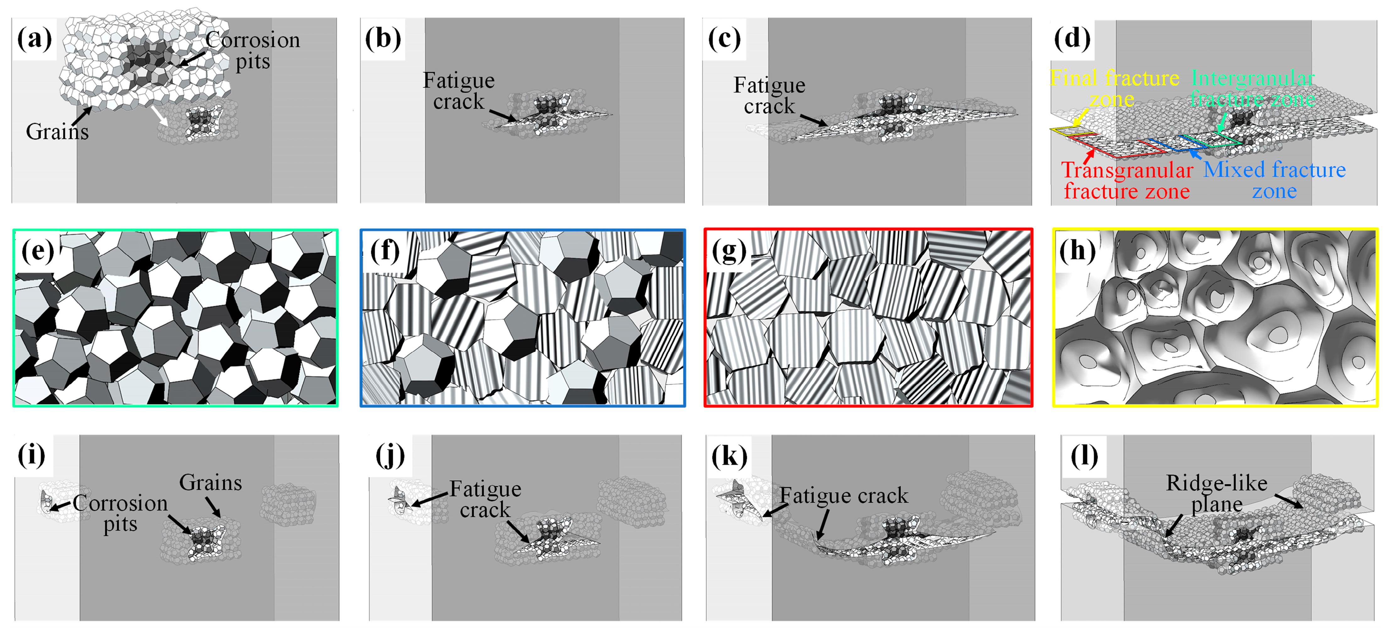
4.2. Corrosion Fracture Mechanism of 5083/6005A Welded Joints

The corrosion fatigue damage of aluminum alloys can generally be divided into four stages: surface oxide film breakdown, pitting corrosion formation, pit-to-crack transition, and crack propagation [48,49]. Surface oxide film breakdown and pitting corrosion formation were discussed in detail in Section 4.1. For the pit-to-crack transition stage, the presence of corrosion pits affects the crack initiation sites [4]. Yadav et al. [19] showed that corrosion pits easily serve as crack nucleation sites due to the generation of stress concentrations under cyclic stress, which agreed well with our experimental results. The irregularly shaped corrosion pits are observed near the crack nucleation sites (Figure 7b,c). Furthermore, the hydrogen embrittlement occurs in the matrix of the corrosion pit interior, leading to the decreased time of the pit-to-crack transition [50]. Therefore, the crack initiation life of 5083/6005A welded joints is severely reduced due to corrosion.
For the crack propagation stage, microstructural characteristics (such as grain boundaries) at the crack tip affect the mode of crack propagation [51]. Qin et al. [52] showed that the intergranular corrosion reduces the grain boundary strength, facilitating the separation of adjacent grains during the fracture process, which increases the crack propagation rate and intergranular fracture. In our results, intergranular fracture can be observed in fatigue fractures, with corrosion products distributed along grain boundaries, as shown in Figure 7d. This indicates that intergranular corrosion occurred in the 5083/6005A weld joints, which reduces the grain boundary strength. Moreover, it is possible for the grain boundary strength between some adjacent grains to remain relatively intact in areas with slight intergranular corrosion, despite the general trend of weakening. When the crack propagation direction significantly deviates from grain boundaries, these adjacent grains are difficult to separate due to the small stress component along these boundaries, resulting in transgranular fractures, as shown in Figure 7e. Therefore, the fracture mode gradually transitions from intergranular fracture to transgranular fracture. In addition, multiple cracks influence the fracture morphology during the crack propagation process [51]. When two cracks approach, their propagation interferes with each other due to the change in stress fields at their tips, causing the cracks to deviate from their initial propagation paths and propagate towards another crack [52]. Eventually, these two cracks merge, forming the ridge-like plane (Figure 10a).
As a high Mg-content aluminum alloy, 5083 has a better corrosion resistance than 6005A, but exhibits a higher SCC sensitivity [15]. Sankaran et al. [53] suggest that the SCC sensitivity of 5083 aluminum is attributed to the formation of a secondary phase (Al3Mg2) with a network structure at the grain boundaries. This formation leads to intergranular corrosion, rapidly accelerating the crack propagation rate under cyclic stress. Therefore, the corrosion damage on the 5083 side of 5083/6005A welded joints is relatively mild when not enduring stress, leading to fracture in the HAZ of the 6005A base materials, as shown in Figure 7i, Figure 8f, and Figure 9f. However, the corrosion damage on the 5083 side becomes severe when enduring stress, making it more prone to fracture in the HAZ of the 5083 base materials, as shown in Figure 10a.
Based on the above analysis and experimental results, the fatigue fracture model of 5083/6005A welded joints has been established, as shown in Figure 14. For the case of the single crack, the corrosion pit is formed on the surface of 5083/6005A welded joints due to corrosion, and their interior exhibits grain detachment, as shown in Figure 14a. After cyclic loading, the cracks form at the corrosion pits (Figure 14b) and propagate along the grain boundaries (Figure 14e). As the number of cyclic loads increases, the cracks gradually lengthen (Figure 14c), and their propagation mode gradually transitions from intergranular to transgranular fracture (Figure 14f). In the mid-stage of crack propagation, the crack propagation mode becomes transgranular (Figure 14g). When the crack length reaches the critical crack size, the 5083/6005A welded joints fracture (Figure 14d), leading to the formation of dimples in the final fracture zone (Figure 14h).
In the case of multiple cracks, the initial crack propagation process in 5083/6005A welded joints is essentially similar to that of the single crack. As the number of cycles increases, the fracture mode gradually transforms from intergranular to transgranular fracture, as shown in Figure 14i,j. During the mid-stages of crack propagation, the direction of crack propagation changes due to the influence of other cracks, with the crack propagating towards another crack site, as shown in Figure 14k. When two cracks converge, they form a ridge-like plane, as shown in Figure 14l.

5. Conclusions

The effects of different corrosion conditions (3.5% NaCl + 0.01 mol/L NaHSO3, 3.5% NaCl, 0.6 mol/L NaHSO3, and 3.5% NaCl + 0.01 mol/L NaHSO3-75 MPa) on the mechanical properties of 5083/6005A welded joints were investigated, the corrosion mechanisms for Cl and SO42− was elucidated, and fatigue fracture models for the pre-corrosion sample were established. The following conclusions can be obtained:
  • The most severe corrosion damage of 5083/6005A welded joints occurs in 3.5% NaCl + 0.01 mol/L NaHSO3, particularly under enduring stress, which is attributed to the increased pH from the NaHSO3 addition. In comparison, the slightest corrosion damage is found in 0.6 mol/L NaHSO3, where the deposition of Al2(SO4)3 on the surface effectively inhibits further corrosion.
  • The crack initiation life of 5083/6005A welded joints for pre-corrosion is significantly decreased due to the formation of corrosion pits and hydrogen embrittlement. The corrosion pits cause stress concentrations and provide nucleation sites for cracks, reducing the crack initiation life. Additionally, the hydrogen embrittlement accelerates the transition from pit to crack.
  • The crack propagation life of 5083/6005A welded joints for pre-corrosion is reduced due to the intergranular corrosion. The intergranular corrosion weakens the bonding between adjacent grains, leading to the faster crack propagation rate and intergranular fracture at the early stages.
  • 5083/6005A welded joints fracture in the HAZ of the 6005A side under non-stress corrosion, whereas they fracture in the HAZ of the 5083 side under stress corrosion. The 5083 material has a superior corrosion resistance compared to 6005A, while its SCC resistance is inferior to 6005A, which leads to changes in the fracture location under enduring stress.

Author Contributions

Conceptualization, H.W., Y.C. and G.H.; methodology, H.W., D.L., Y.C. and G.H.; software, H.W.; validation, D.L., Y.C. and G.H.; formal analysis, H.W., D.L. and G.H.; investigation, H.W. and G.H.; resources, and G.H.; data curation, H.W., Y.C. and G.H.; writing—original draft preparation, H.W.; writing—review and editing, H.W., D.L., Y.C. and G.H.; visualization, H.W.; supervision, Y.C. and G.H.; project administration, Y.C. and G.H.; funding acquisition, G.H. All authors have read and agreed to the published version of the manuscript.

Funding

This research was funded by the National Natural Science Foundation of China (grant number 52075166 and U21A20130); the Natural Science Foundation of Hunan Province (grant number 2023JJ10019); the Hunan Talent Innovation Project (grant number 2023RC1068); and China Postdoctoral Science Foundation (grant number 2022M712642).

Data Availability Statement

The original contributions presented in the study are included in the article, further inquiries can be directed to the corresponding authors.

Acknowledgments

The authors thank Xianghao Zeng and Yunqing Hu for their valuable contributions to this research.

Conflicts of Interest

Author Guanqiang He was employed by the company Zhuzhou CRRC Times Electric Co., Ltd. The remaining authors declare that the research was conducted in the absence of any commercial or financial relationships that could be construed as a potential conflict of interest.

References

  1. Fan, L.T.; Ma, J.J.; Zou, C.X.; Gao, J.; Wang, H.S.; Sun, J.; Guan, Q.M.; Wang, J.; Tang, B.; Li, J.S.; et al. Revealing foundations of the intergranular corrosion of 5XXX and 6XXX Al alloys. Mater. Lett. 2020, 271, 127767. [Google Scholar] [CrossRef]
  2. Chen, Y.Q.; Xu, J.B.; Pan, S.P.; Li, N.B.; Ou, C.G.; Liu, W.H.; Song, Y.F.; Tan, X.R.; Liu, Y. Effect of T6I6 treatment on dynamic mechanical behaviour of Al-Si-Mg-Cu cast alloy and impact resistance of its cast motor shell. J. Cent. South Univ. 2022, 29, 924–936. [Google Scholar] [CrossRef]
  3. Lu, W.; Ma, C.P.; Gou, G.Q.; Fu, Z.H.; Sun, W.G.; Che, H.; Chen, H.; Gao, W. Corrosion fatigue crack propagation behavior of A7N01P-T4 aluminum alloy welded joints from high-speed train underframe after 1.8 million km operation. Mater. Corros. 2021, 72, 879–887. [Google Scholar] [CrossRef]
  4. Song, H.P.; Jiang, S.; Sun, L.S.; Zhang, H.; Leen, S.B.; Du, J. Fatigue damage evolution and failure of pre-corroded aluminum alloy 7075-T651 under air and corrosion environments. Fatigue Fract. Eng. Mater. Struct. 2023, 46, 3458–3476. [Google Scholar] [CrossRef]
  5. Cavalcante TR, F.; Pereira, G.S.; Koga, G.Y.; Bolfarini, C.; Bose, W.W.; Avila, J.A. Fatigue crack propagation of aeronautic AA7050-T7451 and AA2050-T84 aluminum alloys in air and saline environments. Int. J. Fatigue 2022, 154, 106519. [Google Scholar] [CrossRef]
  6. Peng, C.; Cao, G.; Gu, T.; Wang, C.; Wang, Z.Y.; Sun, C. The corrosion behavior of the 6061 Al alloy in simulated Nansha marine atmosphere. J. Mater. Res. Technol. 2022, 19, 709–721. [Google Scholar] [CrossRef]
  7. Adams, F.V.; Akinwamide, S.O.; Obadele, B.; Olubambi, P.A. Comparison study on the corrosion behavior of aluminum alloys in different acidic media. Mater. Today Proc. 2021, 38, 1040–1043. [Google Scholar] [CrossRef]
  8. Zhao, Q.Y.; Guo, C.; Niu, K.K.; Zhao, J.B.; Huang, Y.H.; Li, X.G. Long-term corrosion behavior of the 7A85 aluminum alloy in an industrial-marine atmospheric environment. J. Mater. Res. Technol. 2021, 12, 1350–1359. [Google Scholar] [CrossRef]
  9. Mishra, R.K. Study the effect of pre-corrosion on mechanical properties and fatigue life of aluminum alloy 8011. Mater. Today Proc. 2020, 25, 602–609. [Google Scholar] [CrossRef]
  10. Loto, R.T. Effect of SO42− and Cl anionic attack on the localized corrosion resistance and morphology of 409 ferritic stainless steel. Results Phys. 2019, 12, 738–742. [Google Scholar] [CrossRef]
  11. Jin, J.J.; Lu, W.; Fu, Z.H.; Zhu, J.Y.; Chen, W.J.; Guo, G.Q. Corrosion fatigue crack growth in A7N01S-T5 aluminum alloy MIG welded joints. J. Mater. Res. Technol. 2023, 23, 2202–2218. [Google Scholar] [CrossRef]
  12. Zhu, Z.P.; Jiao, X.C.; Tang, X.Y.; Tang, X.Y.; Lu, H.W. Effects of SO42− concentration on corrosion behaviour of carbon steels. Anti-Corros. Methods Mater. 2015, 62, 322–326. [Google Scholar] [CrossRef]
  13. Yadav, V.K.; Gaur, V.; Singh, I.V. Corrosion-fatigue behavior of welded aluminum alloy 2024-T3. Int. J. Fatigue 2023, 173, 107675. [Google Scholar] [CrossRef]
  14. Ge, F.; Zhang, L.; Tian, H.Y.; Yu, M.D.; Liang, J.M.; Wang, X. Stress corrosion cracking behavior of 2024 and 7075 high-strength aluminum alloys in a simulated marine atmosphere contaminated with SO2. J. Mater. Eng. Perform. 2020, 29, 410–422. [Google Scholar] [CrossRef]
  15. Zhang, Z.; Xu, Z.L.; Sun, J.; Zhu, M.T.; Yao, Q.; Zhang, D.J.; Zhang, B.W.; Xiao, K.; Wu, J.S. Corrosion behaviors of AA5083 and AA6061 in artificial seawater: Effects of Cl, HSO3 and temperature. Int. J. Electrochem. Sci. 2020, 15, 1218–1229. [Google Scholar] [CrossRef]
  16. Altenbach, C.; Schnatterer, C.; Mercado, U.A.; Suurinen, J.P.; Zander, D.; Requena, G. Synchrotron-based holotomography and X-ray fluorescence study on the stress corrosion cracking behavior of the peak-aged 7075 aluminum alloy. J. Alloys Compd. 2020, 817, 152722. [Google Scholar] [CrossRef]
  17. Oger, L.; Andrieu, E.; Odemer, G.; Peguet, L.; Blanc, C. About the role of the hydrogen during stress corrosion cracking of a low-copper Al-Zn-Mg alloy. J. Alloys Compd. 2022, 900, 163391. [Google Scholar] [CrossRef]
  18. Selvamani, S.T. Microstructure and stress corrosion behaviour of CMT welded AA6061-T6 aluminium alloy joints. J. Mater. Res. Technol. 2021, 15, 315–326. [Google Scholar] [CrossRef]
  19. Yadav, V.K.; Gaur, V.; Singh, I.V. Effect of pre-corrosion on crack initiation behavior of friction stir welded aluminum alloy 2024-T3 in high and low cycle fatigue regimes. Int. J. Fatigue 2024, 179, 108037. [Google Scholar] [CrossRef]
  20. Wu, L.J.; Yang, B.; Han, X.H.; Ma, G.L.; Xu, B.X.; Liu, Y.H.; Song, X.G.; Tan, C.W. The microstructure and mechanical properties of 5083, 6005A and 7N01 aluminum alloy gas metal arc-welded joints for high-speed train: A comparative study. Metals 2022, 12, 213. [Google Scholar] [CrossRef]
  21. Moreto, J.A.; Dos, S.M.; Ferreira, M.O.; Carvalho, G.S.; Gelamo, R.V.; Aoki, I.V.; Taryba, M.; Bose, F.W.W.; Fernandes, J.C.S. Corrosion and corrosion-fatigue synergism on the base metal and nugget zone of the 2524-T3 Al alloy joined by FSW process. Corros. Sci. 2021, 182, 109253. [Google Scholar] [CrossRef]
  22. Bocchi, S.; Cabrini, M.; Urso, G.; Giardini, C.; Lorenzi, S.; Pastore, T. Stress enhanced intergranular corrosion of friction stir welded AA2024-T3. Eng. Fail. Anal. 2020, 111, 104483. [Google Scholar] [CrossRef]
  23. Lu, H.; Xu, W.; Wang, H.; Wang, X.Z. Microstructure evolution and its effect on the corrosion of dissimilar aluminum alloys friction stir welding joint. Corros. Sci. 2023, 220, 111249. [Google Scholar] [CrossRef]
  24. Davoodi, A.; Esfahani, Z.; Sarvghad, M. Microstructure and corrosion characterization of the interfacial region in dissimilar friction stir welded AA5083 to AA7023. Corros. Sci. 2016, 107, 133–144. [Google Scholar] [CrossRef]
  25. GB/T20120.1-2006; Corrosion of Metals and Alloys-Corrosion Fatigue Testing-Part 1: Cycles to Failure Testing. Standardization Administration of China: Beijing, China, 2006.
  26. ASTM E8; Standard Test Methods for Tension Testing of Metallic Materials. American Society of Testing: West Conshohocken, PA, USA, 2013.
  27. HB 5287-96; Test Method for Axial Loading Fatigue of Metallic Materials. Aviation Industry Corporation of China: Beijing, China, 1996.
  28. GB/T 24196-2009; Corrosion of Metals and Alloys-Electrochemical Test Methods-Guidelines for Conducting Potentiostatic and Potentiodynamic Polarization Measurements. Aviation Industry Corporation of China: Beijing, China, 2009.
  29. Li, Z.; Chen, L.; Tang, J.; Zhao, G.Q.; Zhang, C.S.; Chu, X.R. Microstructure evolution, plastic anisotropy, and intergranular corrosion of Al-Mg-Si sheet processed through a combination of hot extrusion and cold rolling. Mater. Charact. 2020, 164, 110299. [Google Scholar] [CrossRef]
  30. Wang, B.; Zhang, L.W.; Su, Y.; Mou, X.L.; Xiao, Y.; Liu, J. Investigation on the corrosion behavior of aluminum alloys 3A21 and 7A09 in chloride aqueous solution. Mater. Des. 2013, 50, 15–21. [Google Scholar] [CrossRef]
  31. Yang, X.K.; Zhang, L.W.; Zhang, S.Y.; Liu, M.; Zhou, K.; Mu, X.L. Properties degradation and atmospheric corrosion mechanism of 6061 aluminum alloy in industrial and marine atmosphere environments. Mater. Corros. 2017, 68, 529–535. [Google Scholar] [CrossRef]
  32. Fu, Y.; Richardson, P.; Li, K.K.; Yu, H.; Yu, B.; Donne, S.; Kisi, E.; Ma, T.Y. Transition metal aluminum boride as a new candidate for ambient-condition electrochemical ammonia synthesis. Nano-Micro Lett. 2020, 12, 65. [Google Scholar] [CrossRef] [PubMed]
  33. Sakairi, M.; Otani, K.; Kaneko, A.; Seki, Y.; Nagasawa, D. Analysis of chemical compositions and morphology of surface films formed on 3003 aluminum alloy by immersion in different cation containing model tap waters. Surf. Interface Anal. 2013, 45, 1517–1521. [Google Scholar]
  34. Cao, Y.; Zou, C.; Wang, C.; Liang, H.; Chen, W.J.; Li, W.J. Effect of TiO2 nanoparticles and SDBS on corrosion behavior of 3003 aluminum alloy in aqueous ethylene glycol containing chloride ions at high temperature. J. Alloys Compd. 2021, 873, 159820. [Google Scholar] [CrossRef]
  35. Hoar, T.P.; Mears, D.C.; Rothwell, G.P. The relationships between anodic passivity, brightening and pitting. Corros. Sci. 1965, 5, 279–289. [Google Scholar] [CrossRef]
  36. Hoar, T.P. The production and breakdown of the passivity of metals. Corros. Sci. 1967, 7, 341–355. [Google Scholar] [CrossRef]
  37. Dong, C.F.; Xiao, K.; Xu, L.; Sheng, H.; An, Y.H.; Li, X.G. Characterization of 7A04 aluminum alloy corrosion under atmosphere with chloride ions using electrochemical techniques. Rare Met. Mater. Eng. 2011, 40, 275–279. [Google Scholar]
  38. Wang, S.; Gu, Y.; Geng, Y.; Liang, J.; Zhao, J.; Kang, J. Investigating local corrosion behavior and mechanism of MAO coated 7075 aluminum alloy. J. Alloys Compd. 2020, 826, 153976. [Google Scholar] [CrossRef]
  39. Blücher, D.B.; Svensson, J.E.; Johansson, L.G. Influence of ppb levels of SO2 on the atmospheric corrosion of aluminum in the presence of NaCl. J. Electrochem. Soc. 2005, 152, B397. [Google Scholar] [CrossRef]
  40. Zhang, F.; Nilsson, J.O.; Pan, J.S. In situ and operando AFM and EIS studies of anodization of Al 6060: Influence of intermetallic particles. J. Electrochem. Soc. 2016, 163, C609. [Google Scholar] [CrossRef]
  41. Luo, D.; Li, F.; Xing, G. Corrosion resistance of 6061-T6 aluminium alloy and its feasibility of near-surface reinforcements in concrete structure. Rev. Adv. Mater. Sci. 2022, 61, 638–653. [Google Scholar]
  42. Stannard, T.J.; Williams, J.J.; Singh, S.S.; Sundaram, S.A.S.; Xiao, X.H.; Chawla, N. 3D time-resolved observations of corrosion and corrosion-fatigue crack initiation and growth in peak-aged Al 7075 using synchrotron X-ray tomography. Corros. Sci. 2018, 138, 340–352. [Google Scholar] [CrossRef]
  43. Wang, L.W.; Liang, J.M.; Li, H.; Cheng, L.J.; Cui, Z.Y. Quantitative study of the corrosion evolution and stress corrosion cracking of high strength aluminum alloys in solution and thin electrolyte layer containing Cl. Corros. Sci. 2021, 178, 109076. [Google Scholar] [CrossRef]
  44. Najjar, D.; Magnin, T.; Warner, T.J. Influence of critical surface defects and localized competition between anodic dissolution and hydrogen effects during stress corrosion cracking of a 7050 aluminium alloy. Mater. Sci. Eng. A 1997, 238, 293–302. [Google Scholar] [CrossRef]
  45. Kumar, K.K.; Kumar, A.; Satyanarayana, M. Effect of friction stir welding parameters on the material flow, mechanical properties and corrosion behavior of dissimilar AA5083-AA6061 joints. Proc. Inst. Mech. Eng. Part C J. Mech. Eng. Sci. 2021, 236, 2901–2917. [Google Scholar] [CrossRef]
  46. Chen, Y.Q.; Wu, H.L.; Wang, X.D.; Zeng, X.H.; Huang, L.; Gu, H.Y.; Li, H. Corrosion mechanism and the effect of corrosion time on mechanical behavior of 5083/6005A welded joints in a NaCl and NaHSO3 mixed solution. Crystals 2022, 12, 1150. [Google Scholar] [CrossRef]
  47. Shi, L.X.; Xiang, L.; Tao, J.Q.; Chen, Q.; Liu, J.; Zhong, Y. Actual marine atmospheric pre-corrosion fatigue performance of 7075-T73 aluminum alloy. Metals 2022, 12, 874. [Google Scholar] [CrossRef]
  48. Li, H.; Zhang, J.W.; Wu, S.C.; Zhang, H.N.; Fu, Y.A. Corrosion fatigue mechanism and life prediction of railway axle EA4T steel exposed to artificial rainwater. Eng. Fail. Anal. 2022, 138, 106319. [Google Scholar] [CrossRef]
  49. Luo, Y.; Yuan, P.; Li, G.; Yang, B.; Ao, N.; Li, Z.W.; Wu, Y.; Zhang, G.Z.; Wu, S.C. Corrosion fatigue behavior and life prediction of railway axle EA4T alloy steel with artificial indentation. Eng. Fract. Mech. 2024, 296, 109835. [Google Scholar] [CrossRef]
  50. Guo, T.; Chen, Y.M.; Cao, R.H.; Pang, X.L.; He, J.Y.; Qiao, L.J. Cleavage cracking of ductile-metal substrates induced by brittle coating fracture. Acta Mater. 2018, 152, 77–85. [Google Scholar] [CrossRef]
  51. Song, H.P.; Liu, C.C.; Zhang, H.; Du, J.; Yang, X.D.; Leen, S.B. In-situ SEM study of fatigue micro-crack initiation and propagation behavior in pre-corroded AA7075-T7651. Int. J. Fatigue 2020, 137, 105655. [Google Scholar] [CrossRef]
  52. Qin, H.L.; Zhang, H.; Sun, D.T.; Zhuang, Q.Y. Corrosion behavior of the friction-stir-welded joints of 2A14-T6 aluminum alloy. Int. J. Miner. Metall. Mater. 2015, 22, 627–638. [Google Scholar] [CrossRef]
  53. Sankaran, K.K.; Mishra, R.S. Metallurgy and Design of Alloys with Hierarchical Microstructures; Elsevier: Amsterdam, The Netherlands, 2017. [Google Scholar]
Figure 1. (a) Sampling diagram of 5083/6005A weld joint; (b) schematic diagram of sample dimensions.
Metals 14 00925 g001
Figure 2. Experimental procedure: (a) corrosion test; (b) stress corrosion test; (c) pre-corrosion sample; and (d) tensile and fatigue test.
Metals 14 00925 g002
Figure 3. Tensile properties and stress–strain curves of 5083/6005A welded joints after corrosion at different conditions: (a) mechanical properties; and (b) stress–strain curves.
Metals 14 00925 g003
Figure 4. Fatigue life of 5083/6005A welded joints after corrosion at different conditions.
Metals 14 00925 g004
Figure 5. Corrosion morphology of 5083/6005A weld joints at different conditions: (ad) HAZ of 5083 base materials; (e,f) 6005A base materials; (a,e) 3.5% NaCl + 0.01 mol/L NaHSO3; (b,f) 3.5% NaCl; (c,g) 0.6 mol/L NaHSO3; and (d,h) 3.5% NaCl + 0.01 mol/L NaHSO3-75 MPa.
Metals 14 00925 g005
Figure 6. Tensile fracture morphology of 5083/6005A welded joints after corrosion at different conditions: (a1,a2) uncorroded; (b1,b2) 3.5% NaCl + 0.01 mol/L NaHSO3; (c1,c2) 3.5% NaCl; (d1,d2) 0.6 mol/L NaHSO3; and (e1,e2) 3.5% NaCl + 0.01 mol/L NaHSO3-75 MPa.
Metals 14 00925 g006
Figure 7. Fatigue fracture morphology of 5083/6005A welded joints after corrosion at 3.5% NaCl + 0.01 mol/L NaHSO3: (a) overall fracture morphology; (b,c) crack initiation zone; (d,e) brittle fracture morphology; (f,g) crack propagation zone; (h) final fracture zone; and (i) fracture schematic diagram.
Metals 14 00925 g007
Figure 8. Fatigue fracture morphology of 5083/6005A welded joints after corrosion at 3.5% NaCl: (a) overall fracture morphology; (b) crack initiation zone; (c,d) crack propagation zone; (e) final fracture zone; and (f) fracture schematic diagram.
Metals 14 00925 g008
Figure 9. Fatigue fracture morphology of 5083/6005A welded joints after corrosion at 0.6 mol/L NaHSO3: (a) overall fracture morphology; (b) crack initiation zone; (c,d) crack propagation zone; (e) final fracture zone; and (f) fracture schematic diagram.
Metals 14 00925 g009
Figure 10. Fatigue fracture morphology of 5083/6005A welded joints after corrosion at 3.5% NaCl + 0.01 mol/L NaHSO3-75 MPa: (a) overall fracture morphology; (bf) crack initiation zone; (gj) crack propagation zone; and (k,l) final fracture zone.
Metals 14 00925 g010
Figure 11. Polarization curves of 5083/6005A welded joints after corrosion at different conditions: (a) 5083 base materials; and (b) 6005A base materials.
Metals 14 00925 g011
Figure 12. XPS results of 5083/6005A welded joints after corrosion at different conditions: (a) 3.5% NaCl + 0.01 mol/L NaHSO3; (b) 3.5% NaCl; (c) 0.01 mol/L NaHSO3; (a1c1) 5083 and 6005A survey spectrum; (a2c2) 5083 Al2p spectrum; and (a3c3) 6005A Al2p spectrum.
Metals 14 00925 g012
Figure 13. Corrosion models of 5083/6005A welded joints at different conditions: (a1d1) 3.5% NaCl + 0.01 mol/L NaHSO3; (a2d2) 3.5% NaCl; (a3d3) 0.6 mol/L NaHSO3; (a4d4) 3.5% NaCl + 0.01 mol/L NaHSO3-75 MPa; (a1a4) initial stage of corrosion; (b1b4) pitting stage; (c1c4) corrosion pit expansion stage; and (d1d4) late stage of corrosion.
Metals 14 00925 g013
Figure 14. Fatigue fracture model of 5083/6005A welded joints: (a) initial stage of single crack propagation; (b) early stage of single crack propagation; (c) late stage of single crack propagation; (d) post-fracture of single crack; (e) intergranular fracture zone; (f) mixed fracture zone; (g) transgranular fracture zone; (h) final fracture zone; (i) initial stage of multiple crack propagation; (j) initial stage of multiple crack propagation; (k) late stage of multiple crack propagation; and (l) post-fracture of multiple crack.
Metals 14 00925 g014
Table 1. Chemical compositions of 5083, 6005A, and ER5356 (wt.%).
MaterialsSiFeCuMnMgZnCrTiAl
50830.090.200.010.754.980.020.090.05bal.
6005A0.500.190.010.260.710.020.160.06bal.
ER53560.120.120.080.154.900.120.110.12bal.
Table 2. Polarization parameters of 5083/6005A weld joints after corrosion at different condition.
Experimental Conditions50836005A
Ecorr (v. SCE)/(V)Jcorr/(μA·cm−2)Ecorr (v. SCE)/(V)Jcorr/(μA·cm−2)
Uncorroded−0.5942.00−0.6171.95
A condition−0.6504.01−0.6632.50
B condition−0.6314.50−0.6542.32
C condition−0.6216.17−0.6334.27
D condition−0.7622.23−0.7230.81
Disclaimer/Publisher’s Note: The statements, opinions and data contained in all publications are solely those of the individual author(s) and contributor(s) and not of MDPI and/or the editor(s). MDPI and/or the editor(s) disclaim responsibility for any injury to people or property resulting from any ideas, methods, instructions or products referred to in the content.

