Article

Investigating the Influence Mechanism of Different Shielding Gas Types on Arc Characteristics and Weld Quality in TA2 Laser–Arc Hybrid Welding

1
College of Mechanical Engineering, Zhejiang University of Technology, Hangzhou 310014, China
2
Institute of Laser Advanced Manufacturing, Zhejiang University of Technology, Hangzhou 310014, China
3
Collaborative Innovation Center of High-End Laser Manufacturing Equipment (National “2011 Plan”), Zhejiang University of Technology, Hangzhou 310014, China
*
Author to whom correspondence should be addressed.
Metals 2024, 14(8), 946; https://doi.org/10.3390/met14080946
Submission received: 22 July 2024 / Revised: 11 August 2024 / Accepted: 19 August 2024 / Published: 20 August 2024

Abstract

:
The effective welding of a 6 mm thick TA2 pure titanium medium-thickness plate was achieved by laser–arc hybrid welding (LAHW) with helium–argon mixed shielding gas. Conducted research on the influence of helium–argon mixed shielding gas on plasma and arc characteristics during welding, and its further impact on the microstructure, internal porosity defects, tensile properties, and corrosion resistance of welded joints was explored. The study demonstrated that under the shielding gas with 75% helium, the arc width narrowed significantly from 6.96 mm to 2.61 mm, achieving a 63% reduction, which enhanced the concentration of arc heat flux density. Achieved a well-formed weld with no surface spatter and significantly reduced the internal porosity rate from 3.02% to 0.47%, which is an 84% decrease. Tensile fractures are located in the base material, all exhibiting plastic failure. The corrosion resistance of the welded joint initially increased and then decreased with the increase of helium content in the shielding gas, peaking at 75% helium content.

1. Introduction

Titanium and its alloys, characterized by low density, high strength, excellent corrosion resistance, and good biocompatibility, are widely utilized in industries such as aerospace, automotive, marine, and biomedicine [1,2]. However, due to their low thermal conductivity, reactivity at high temperatures, and poor machinability, enhancing the welding processes of titanium and its alloys has become a focal point of numerous research efforts [3,4]. Laser–arc hybrid welding is a high-quality and efficient non-conventional welding technique [5,6,7] that requires low welding assembly precision, effectively avoids joint cracks, and exhibits superior mechanical properties when welding titanium alloys. However, welding of medium-thick plates with laser–arc hybrid welding may result in welding defects such as a large heat-affected zone, porosity in the joint, and surface spatter. These defects can be attributed to various causes, including the collapse of the laser keyhole leading to porosity, as well as arc instability causing an expanded heat-affected zone and the formation of spatter.
Shielding gas mixtures can have a significant impact on the welding process. Zhong et al. [8] showed that the use of hybrid shielding gas improved the stability of the laser arc composite welding 361L process, improving the service performance. Chen et al. [9] use helium–argon mixed gas shielded welding has improved the quality of the weld, the void ratio of the weld has been significantly reduced, and the joint performance has been improved.
Incorporating helium into the welding shielding gas can effectively enhance the characteristics of laser plasma and the arc. Murphy [10] conducted numerical simulations on the arc temperature field under various shielding gases, revealing that the addition of helium to the shielding gas increases the heat flux density in the central region of the arc. Zhu et al. [11] demonstrated that incorporating 30% helium into the shielding gas enhances the coupling between the laser and the arc, improves the matching between the droplet transfer and the arc pulse cycle, and reduces surface splatter. Lei et al. [12] investigated the effects of 100%Ar and He–Ar shielding gas mixture on the porosity defects of aluminum alloy laser welding. They concluded that under the He–Ar shielding gas mixture, the number of plasmas decreased, the stability of the keyhole improved, the reliability of the weld increased, and the porosity was reduced to less than 1%. Li et al. [13] found that using pure helium as the shielding gas during welding reduces the deviation between the arc and the welding wire axis, resulting in a more stable arc, but it makes the droplet transfer more difficult. Chae [14] compared the effects of helium and argon on the laser-plasma during hybrid welding experiments, concluding that helium significantly suppresses the plasma generated by laser welding and laser–arc hybrid welding. In addition, Ar has a high relative molecular mass and perfect cathode-breaking effect, but the post-weld mechanical properties of the weld metal are underdeveloped, and there are a multitude of pores in the microstructure [15,16,17]. Bermejo et al. [18] welded duplex stainless steel using Laser-Arc Hybrid Welding (LAHW); it was observed that a shielding gas containing 30% helium was used. It exhibits excellent arc stability, molten pool fluidity, smooth weld bead contours, and no surface splatter, whereas pure argon exhibits inferior performance. Xiaoyu Cai et al. [19] found that incorporating a certain amount of helium into the shielding gas during narrow-gap MAG welding can increase the penetration depth by 40%. Chuang Cai et al. [20] used a helium–argon mixed shielding gas in laser-MIG hybrid welding, resulting in improved keyhole stability, increased welding penetration depth, and a reduction in porosity by 80%.
These studies indicate that the proper addition of helium to the shielding gas can effectively suppress the shielding effect of plasma on the incident laser beam, thereby enhancing arc stability and optimizing arc morphology. And reveals the specific influence mechanism of helium–argon mixed shielding gas on the characteristics of electric arc and plasma during the welding process. This study compared the effects of different proportions of helium–argon mixed shielding gases on the plasma, arc characteristics, and weld formation during the welding process. Additionally, the variations in welding joint performance were analyzed. Through these comparisons, the optimal shielding gas process parameters for laser–arc hybrid welding of titanium alloy were obtained, providing an important theoretical basis for optimizing the welding process and improving the welding quality.

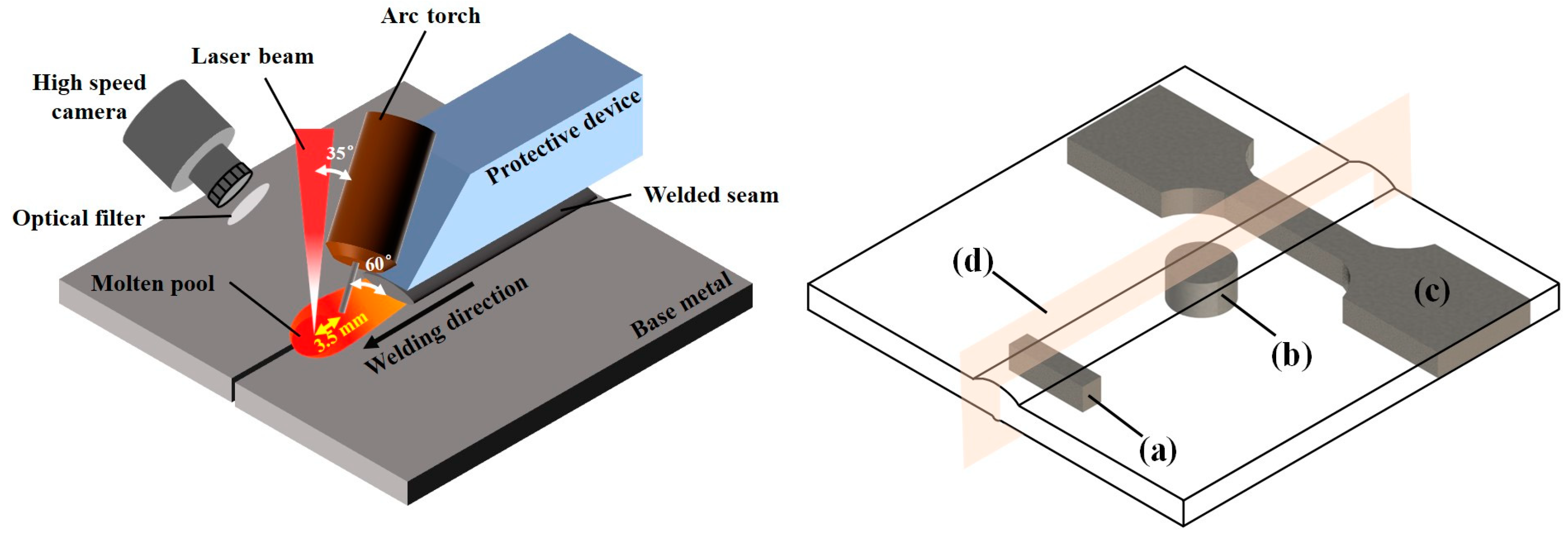
2. Materials and Methods

Welding tests were carried out using TA2 pure titanium samples with dimensions of 100 mm × 50 mm × 6 mm. Table 1 shows the chemical composition of TA2 pure titanium. The filler material chosen is ERTi-2 welding wire with a diameter of 1.2 mm. The tensile strength of the TA2 base material is 372 MPa. Before welding, the oxide layer on the surface of the sample should be removed to ensure that the material is pollution-free. TA2 is abraded with a progression of sandpapers ranging from #80 to #2000 to eliminate the oxide layer, followed by ultrasonic cleaning in anhydrous ethanol for 15 min prior to utilization. To observe the microstructure of the welded joint, Kroll reagent was used for etching.
Figure 1 shows a schematic diagram of the hybrid welding test setup that was used in the experiment: Adopt the welding mode with laser in front and arc in back. A 6 kW fiber laser was employed as the laser heat source, featuring a laser wavelength of 1080 nm and a focal spot diameter of approximately 0.9 mm. A MIG welding machine was used as the arc heat source. To investigate the effects of helium–argon mixed shielding gas on the TA2 laser-MIG hybrid welded joints, the welding process parameters were adjusted as detailed in Table 2.
Before welding, sandpaper and a brush were used to remove surface oxidation, and then ethanol was used to remove surface stains. During the welding process, a high-speed camera with a frame rate of 5000 frames per second was used to observe the welding plasma and arc characteristics, as shown in Figure 1. After welding, tensile test samples, electrochemical test samples, and metallographic observation samples were extracted from the welded joints, as illustrated in Figure 1a–c. The calculation of weld porosity followed the ISO 5817-2023 [21] “Welding-Fusion-welded joints in steel, nickel, titanium and their alloys (beam welding excluded)-Quality levels for imperfections” To compare the porosity of welds under different helium content shielding gases, three cross-sections were randomly selected from each weld, the slicing plane as shown in Figure 1d. Images of these cross-sections were extracted using Image-Pro Plus 6.0, and the porosity of each cross-section was calculated separately. The average value was taken for result analysis.
Table 3 compares the main physical characteristics of argon and helium; these parameters can have an impact on the welding arc. Under the same volume, the mass of argon is about 10 times that of helium, which allows argon to form a more stable protective atmosphere on the surface of the molten pool during the welding process. However, in terms of heat conduction, argon performs relatively poorly, with its heat conduction capability being only one-tenth of that of helium. Helium excels in heat transfer.
Table 4 shows the main ionization energies, including the first and second ionization energies, of key elements involved in the TA2 laser–arc hybrid welding process. According to the table data, the first ionization energy of argon is 15.75 eV, while that of helium is 24.58 eV. This difference indicates that during the welding process, helium is more difficult to ionize to form a plasma compared to argon. Therefore, helium can effectively reduce the inverse bremsstrahlung absorption of the plasma, thereby improving welding quality.

3. Results and Discussion

3.1. Effect of Shielding Gas on the Plasma of Laser–Arc Hybrid Welding of TA2 Plates

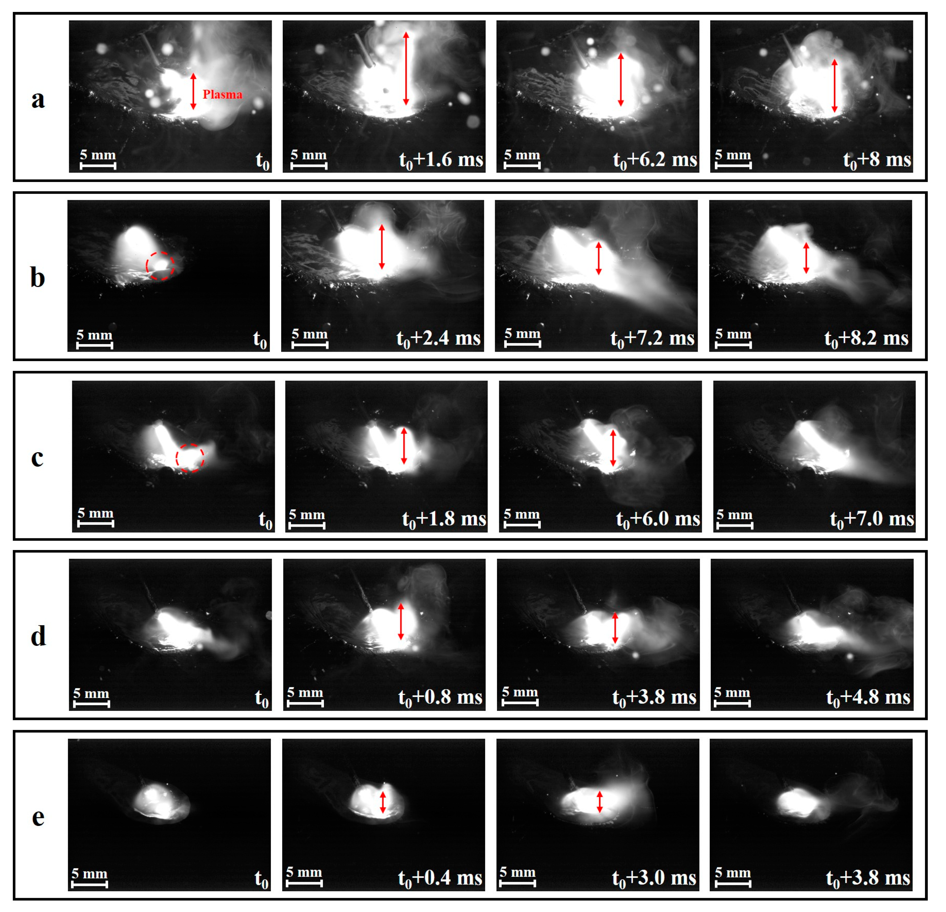
3.1.1. Analysis of High-Speed Plasma Camera Graphics under Different Protective Gases

Figure 2 reveals the dynamic images of the plasma during laser–arc hybrid welding when using helium–argon mixed gas with different proportions of helium as the shielding gas in the laser–arc hybrid welding technology.
The plasma in the laser–arc hybrid welding process plays a crucial role in the welding process and directly affects the energy transfer efficiency. Figure 2 represents the change of the mixed plasma in one cycle, and it can be seen that with the increase of helium content in the shielding gas, As shown by the circles and arrows in the figure, the height of the plasma gradually becomes smaller [22,23]. When the helium content in the protective gas is higher than 75%, the mixed plasma is compressed to the surface of the specimen, and the arc conduction region is compressed. At 100% helium protection, the mixed plasma is compressed into the laser-induced keyhole, as shown in Figure 2e. As the helium percentage is increased, the stability of the arc increases and its arc column becomes more focused. As shown in Figure 2c, after the helium content reaches 50%, the width of the arc narrows considerably and burns steadily between the wire tip and the molten pool during the rising phase of the arc pulse current. As the helium percentage in the shielding gas increases further, the arc is further constrained to the surface layer of the molten pool, resulting in a distortion of the shape, as illustrated in Figure 2d,e. With 100% helium protection, the arc width is almost completely compressed into the molten pool.

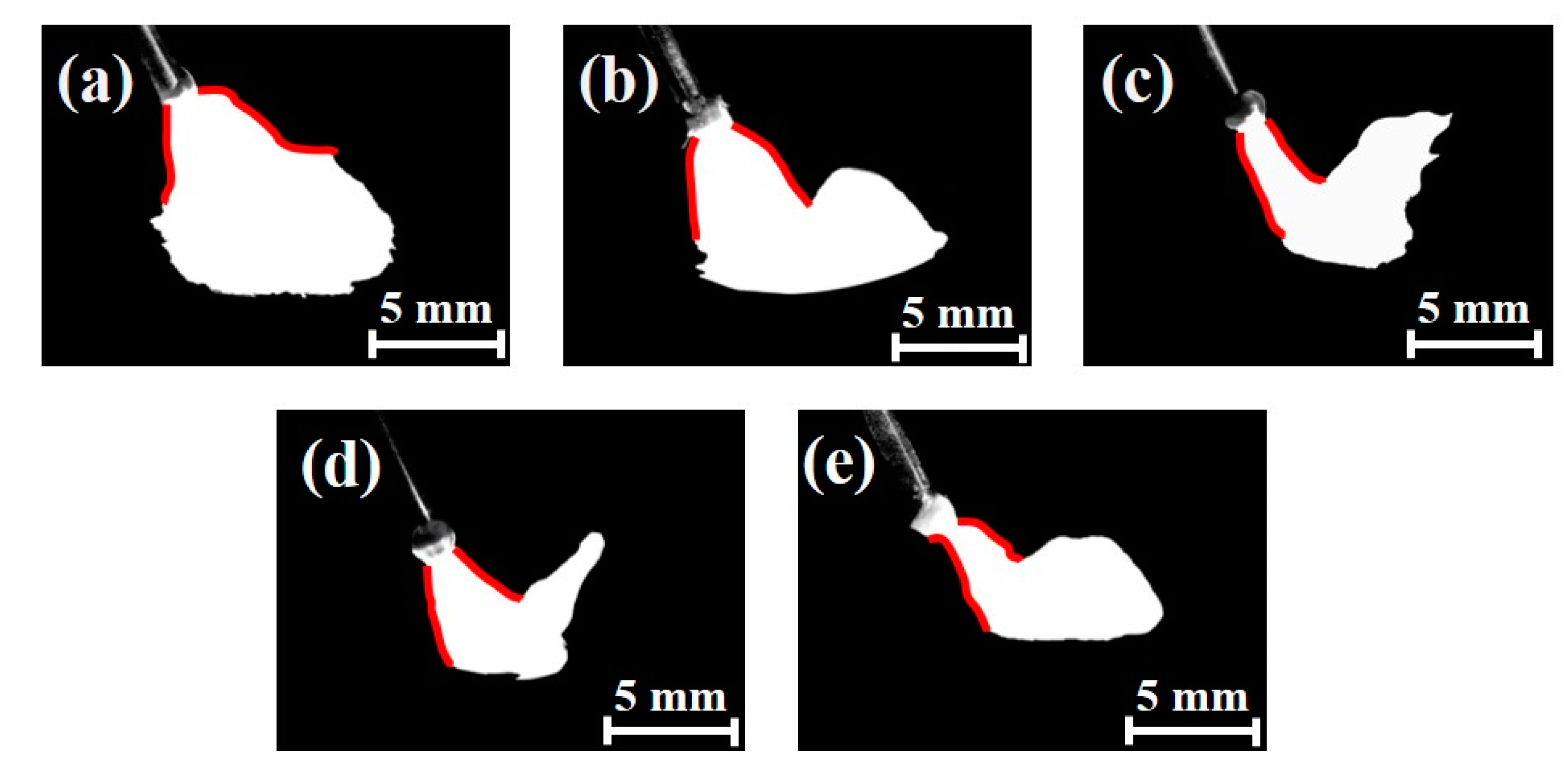
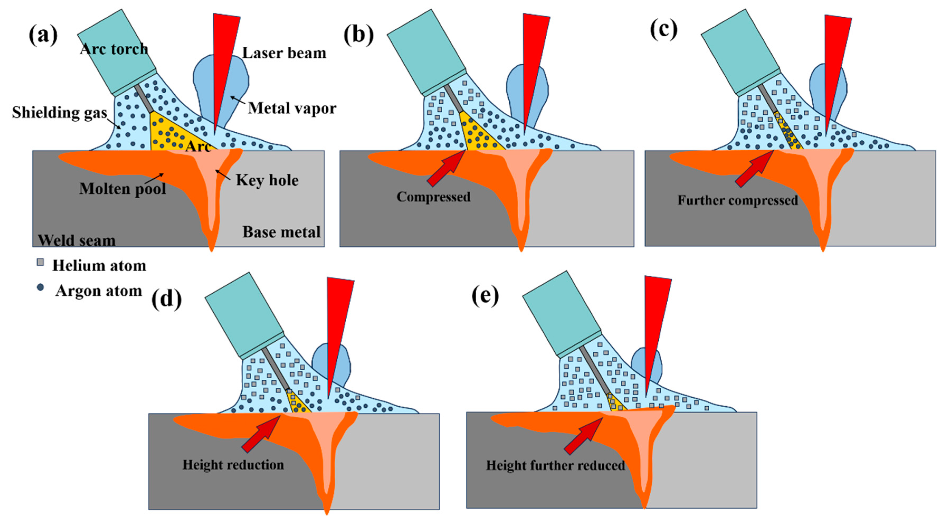
3.1.2. Effects of Different Protective Gases on Arc Morphology

In Figure 3, it is evident that the utilization of a helium–argon mixed gas as the shielding medium during the welding process resulted in a pronounced arc contraction in comparison to welding employing pure argon gas. This observed arc contraction bears a significant correlation with the focusing intensity of the heat source. Through the utilization of a high-speed camera for precise observation of the welding arc, this notable phenomenon was captured and documented. The arc has been labeled in the figure using the red line. All images were taken during the peak stage of the pulsed current.
To reveal the impact of varying He content in the shielding gas on arc plasma, a statistical analysis of arc diameters under different shielding gases was conducted, as illustrated in Figure 4a. It was observed that when welding with a helium–argon mixed gas as the shielding medium, the arc width decreased significantly compared to welding with 100% argon gas. Furthermore, as the helium content in the shielding gas increased, the arc width became even narrower. As illustrated in Figure 5b, when the helium content reached 50%, the arc width was compressed from 6.96 mm to 2.61 mm, representing a 63% reduction.
Research indicates that the introduction of a certain amount of helium into the shielding gas significantly reduces the height of the laser–arc hybrid plasma. When the arc current reaches its peak value, the arc width decreases noticeably, resulting in a longer and narrower arc when viewed from the side of the weld. As illustrated in Figure 5b, in a shielding atmosphere consisting of 75% argon and 25% helium, it was observed that the arc remains stable during ignition, with a slight reduction in arc width. As the helium content of the shielding gas rises to 50%, as shown in Figure 5c, the morphology of the arc becomes significantly more focused during the rising edge phase of the arc pulse, with the entire arc becoming more elongated and continuing to arc steadily between the tip of the laser-actuated keyhole and the wire end droplet. At a helium content of 75%, the arc is further constrained to the surface of the molten pool, which results in a distorted arc morphology, as shown in Figure 5d,e. Due to the higher ionization energy and greater thermal conductivity of helium, a higher current is needed to maintain the energy required for arc initiation to maintain the stability of the welding process at a constant wire feed rate. However, the magnitude of the current is fixed before welding, resulting in the arc being maintained by shortening its length. The shortening of the arc length is particularly noticeable at the low base value stage of the pulse current. Because the arc is difficult to continue to burn stably, the phenomenon of arc quenching, which is the sudden extinguishing of the arc, often occurs. When this happens, laser radiation becomes the primary force to maintain the arc burning.
Murphy et al. [10] research shows that during the welding process, when the helium content in the shielding gas was under 50%, the thermal conductivity of the mixed gas significantly increased during arc conduction, reaching as much as twice the thermal conductivity of pure argon gas. This increased thermal conductivity around the arc, causing the arc column to be strongly cooled by the surrounding environment. Consequently, the arc is contracted to reduce heat loss and maintain energy balance. As shown in Figure 5b,c, with the increase of helium content, the arc column is gradually compressed. When the helium content reaches 50%, the arc column is compressed to a minimum width of 2.61 mm.
When the helium content in the mixed shielding gas exceeds 50%, the thermal conductivity of the mixed gas increases further, which is approximately four times that of pure argon. As a result, the width of the arc column is further compressed. Additionally, the electrical conductivity of the mixed gas gradually decreases, which makes it increasingly difficult to conduct. As a result, the arc was conducted only when the welding wire was near the workpiece surface. Because conduction occurred in an environment with a higher argon content, the width of the arc slightly increased, resulting in an extended elongation during welding. At this time, the welding effect was particularly stable, with minimal arc oscillation. The laser keyhole remained steady and hardly collapsed, obtaining excellent penetration by the hybrid heat source. Additionally, the heat source became more focused, narrowing the heat-affected zone and elevating the temperature of the molten pool [24].
Due to the irradiation of a high-energy laser, the base metal evaporates and ionizes, resulting in the formation of metal vapors and plasma. When the protective gas is pure helium, the gas conductivity is about half that of pure argon, which makes arc conductivity challenging. The arc can only form a conductive channel through the metal vapors, resulting in a more significant offset of the arc towards the laser side. In the high-speed image, the performance of the laser on the arc of the attraction and stabilization phenomenon. As shown in Figure 2e, the arc will form a conductive pass only when the tip of the wire extends into the keyhole or even deep into the molten pool. This leads to an unstable welding process, and the arc goes out from time to time. This leads to unstable heat input [25].

3.1.3. Analysis of Arc Heat Flux Density under Different Protective Gases

In this section, a high-speed camera was used to record the morphological changes of the arc during laser–arc hybrid welding under different shielding gases. The heat flux density and heat source concentration of the arc under various welding conditions with different shielding gases were analyzed. The Gaussian heat source model, which exhibits a normal distribution, was selected to simulate the heat source characteristics of arc welding [20]. The distribution function for a Gaussian heat source is as follows [26]:
q r = q m exp k r 2
In the Equation, k is the heat source concentration coefficient; r is the distance from an arbitrary point to the center of the arc.
The heat source model in Figure 5 assumes that during the welding process, the coverage area of the arc is limited. This area is defined by a diameter denoted as R n , and it is hypothesized that this specific region bears 95% of the total arc heat. Furthermore, the distribution function of arc heat flux density on the plane of maximum arc diameter can be obtained:
q ( R n ) = 0.05 q m
k = 4 ln 20 R n 2
q r = 4 ln 20 π R n 2 η U I exp ( 4 ln 20 R n 2 r 2 )
Based on the arc width, the heat source concentration coefficient can be calculated (the value of k), as shown in Table 5.
The heat flow density distribution of the arc can be obtained according to the Gaussian distribution formula of the arc heat source. Figure 6 shows the heat flow density distribution of the arc. As shown in Figure 6, the distribution of arc heat flux density exhibits significant differences with varying helium content. When the helium content reaches 50%, the heat flux density at the center of the arc attains its maximum value, while the distribution in the high-temperature region shows an opposite trend. In comparison, during pure argon welding, the high-temperature zone is more widely distributed, while the central heat flux density decreases accordingly. In pure argon welding, the dispersion of the arc is most significant. As the helium content increases, the high-temperature region of the arc gradually shrinks, and the central heat flux density gradually increases. When the helium content reaches 50%, the central heat flux density peaks, thereby increasing the temperature at the center of the molten pool.
During the welding process, the welding pool was fully covered by the shielding gas. Because the ionization energy of argon is lower than that of helium, the conductivity of the arc was limited in argon-rich areas, resulting in a relatively higher helium content around the arc. The high thermal conductivity of helium caused the arc column to be strongly cooled by the surrounding shielding gas, forming a cooling layer around the arc. The arc column was strongly compressed, reducing the conductive area of the effective arc. The arc current primarily flowed through the high-temperature region at the center of the arc column in the past, leading to an accumulation of charged particles in the high-temperature ionized zone. The higher the thermal conductivity of the shielding gas, the more significant the thermal compression effect on the arc, resulting in a reduction of the arc’s actual cross-sectional area. Given that helium has a higher thermal conductivity than argon, its thermal compression effect on the arc is more significant [23,27]. With the increase in plasma energy density in the arc, the heat source becomes more concentrated. Because the arc tends to choose high-temperature, easily ionized areas for conduction, this limits arc oscillation caused by unstable droplet transfer, thereby reducing the weld bead width.

3.2. Effect on Welded Joints

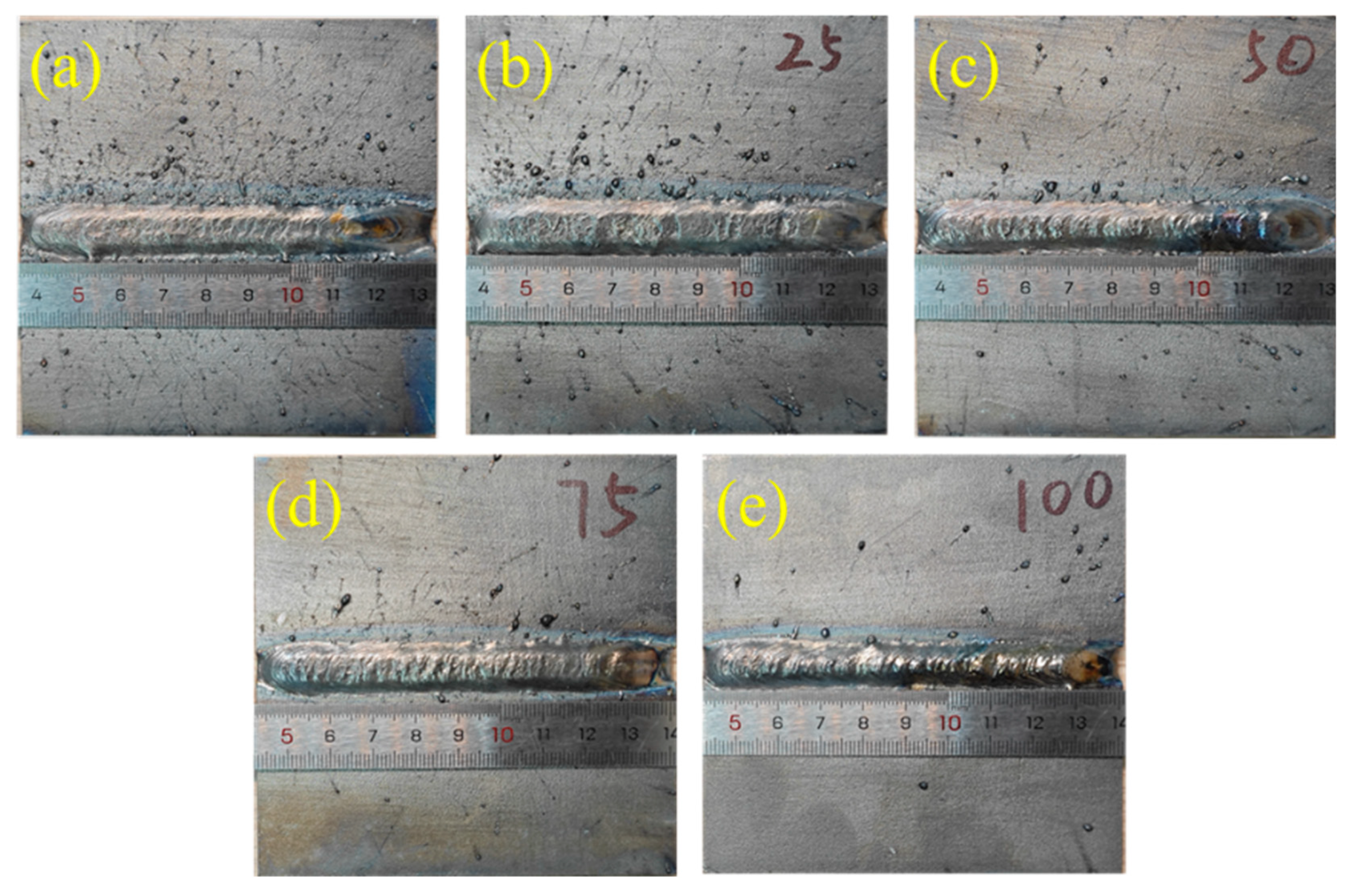
3.2.1. Effect of Different Shielding Gases on the Macroscopic Morphology of Welded Joints

Figure 7 demonstrates the formation of weld surfaces under various proportions of helium–argon mixed shielding gases during laser–arc hybrid welding. When using pure argon as the shielding gas, the weld formation was suboptimal, exhibiting indistinct fish-scale patterns on the surface, along with small pores formed due to the escape of gas bubbles. Additionally, severe splattering was observed around the weld. However, as the helium content increased and exceeded 50% of the mixture, the splattering around the weld decreased significantly, and the fish-scale patterns on the surface became more distinct, presenting a complete arcuate shape overall. Nevertheless, when pure helium was employed as the shielding gas, although the weld surface was free from splatter defects, the occurrence of arc interruption led to discontinuities and an uneven surface morphology in the weld formation.
As shown in Figure 8 and Figure 9, with the increasing content of helium, the width of the heat-affected zone of the joint gradually decreases while the penetration depth gradually increases, as shown by the weld area marked by the yellow line in the figure. This confirms that the addition of helium contributes to compressing the arc and enhancing the welding penetration efficiency.

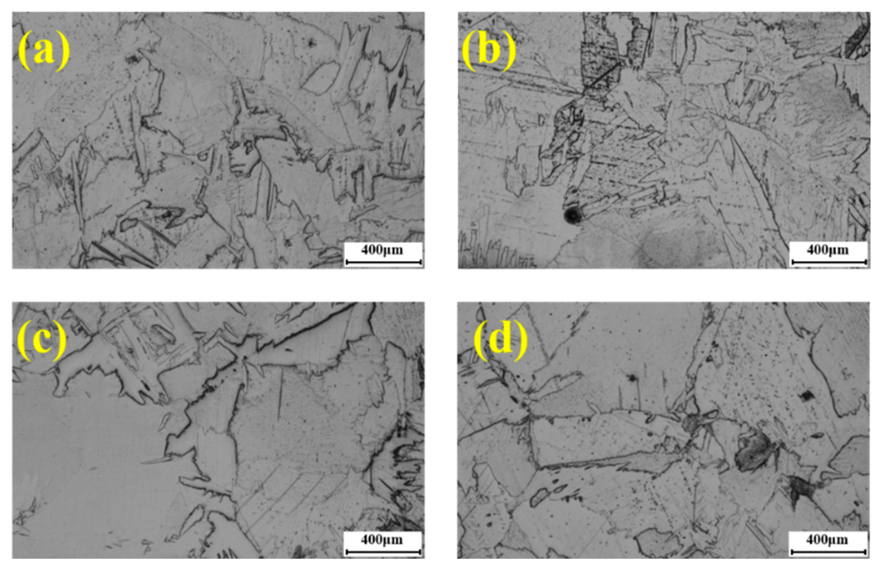
3.2.2. Microstructure Characterization of Welded Joints under Different Shielding Gases

Figure 10a,c exhibit a comparative analysis of the microstructural morphologies of welded joints under pure argon and pure helium shielding gases. The primary factor influencing these microstructural changes is the cooling rate. In the case of welding joints protected by pure argon, the lower temperature of the molten pool restricts the growth rate of the α phase, resulting in smaller grain sizes and denser grain boundaries in the arc zone compared to those under pure helium protection. A similar trend can also be observed in Figure 10b,d.
As the heat input to the welded joint increased due to an increase in the helium content of the shielding gas, the molten pool temperature rose, and the cooling time was prolonged. Consequently, the β-phase in the weld continued to grow, and the α’ lamellar structure formed by the phase transition grew, leading to an increase in the width of the lamellae. Since the length of α’ is primarily influenced by the size of the original β crystals, the increase in heat input also resulted in an increase in the length of the α’ lamellae. The grain size under pure helium protection was larger compared to the grain size of the welded joints obtained under argon protection. In the heat-affected region of the welded joints, the β-phase was transformed into a jagged α-phase, which underwent solid-state phase transformation [27].

3.2.3. Effect of Different Shielding Gases on Porosity Defects in Welded Joints

The composition of gas shielding, especially helium content, was found to have a significant effect on the formation of porosity defects during TA2 laser–arc hybrid welding. As shown in Figure 11, the distribution characteristics of the porosity defects were investigated by extracting laser–arc hybrid welded joints with different helium contents. When the shielding gas is pure argon, the number of porosities is high, the size is large, and the porosity rate is 3.02%, while under the shielding atmosphere with 25% helium content, the porosity defect rate decreases significantly to 1.27%, and the size of the porosity decreases significantly. Continuing to increase the helium content, the porosity decreases slowly and reaches 0.89% and 0.47% after the helium content exceeds 50%, respectively. At 100% helium, the porosity reaches a minimum of about 0.42%, with a reduction of up to 86% in the porosity defect rate compared to pure argon.
Observation of the morphological characteristics of the pores in the welds revealed that the pores in the welds under 100% argon protection were large and showed a tendency to overflow toward the surface of the molten pool. With the increase of helium content in the shielding gas, the number of porosities in the weld decreased significantly. This is due to the addition of helium suppresses the plasma and reduces the shielding effect of the plasma on the laser, which enhances the stability of the keyhole and reduces the probability of porosity generation. At the same time, due to the concentration of the arc energy and the increase of the arc heat flow density, the melt pool temperature is increased, which prolongs the solidification time of the melt pool and gives more chances for the larger pores to float up and escape.
With the gradual increase in helium content, the molten pool temperature continued to rise, allowing even small pores sufficient time to surface in the weld, thus further reducing the number of pores in the weld. Research has shown that by adjusting the helium content in the shielding gas, the formation of porosity in the weld can be effectively reduced, thus optimizing the quality of the joint.

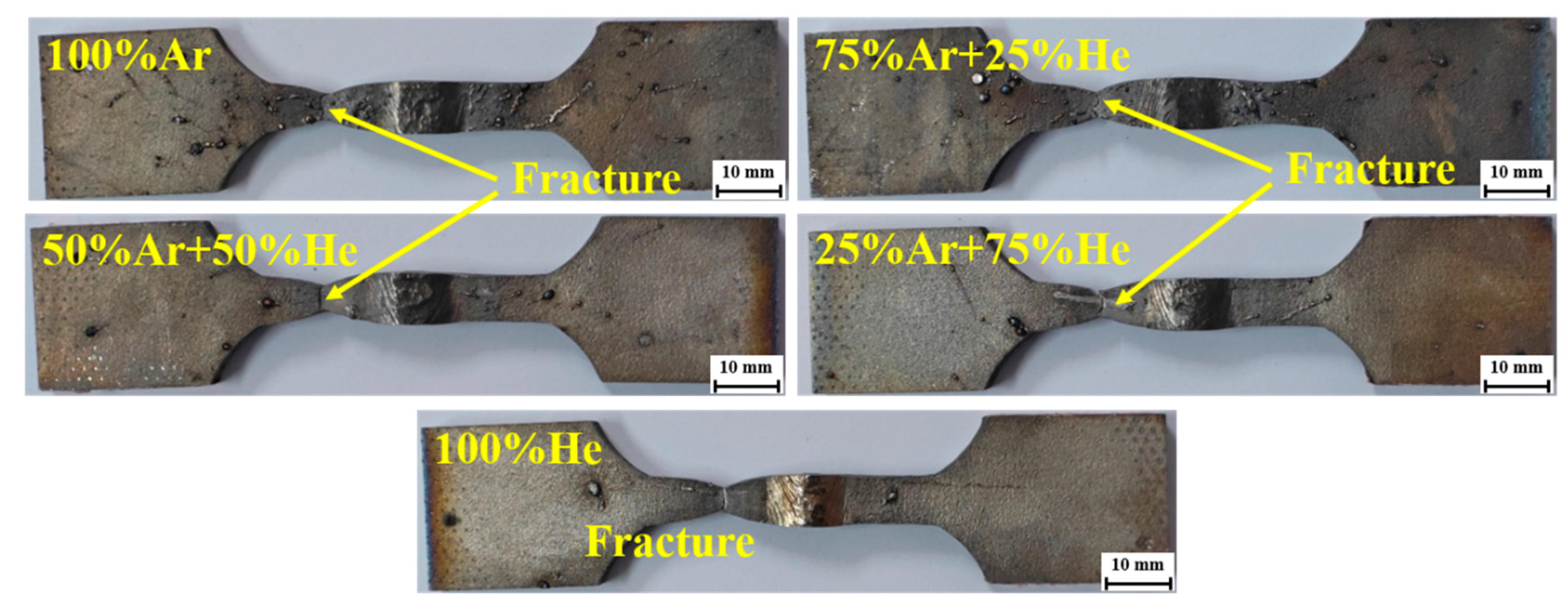
3.3. Effect of Different Shielding Gases on Tensile Properties of Welded Joints

To investigate the effect of different helium content shielding gases on the tensile strength of the TA2 laser–arc hybrid weld head, the tensile properties of the joints were tested. Figure 12 shows the comparison of the tensile test curves of TA2 hybrid welding heads under different shielding gases, and Table 6 shows the specific results of the tensile tests. As shown in Table 6, when different gas mixtures are used as welding shielding gases, the tensile strength of the laser–arc hybrid welded joints is generally higher than that of the base material of 372 MPa. Under 100% argon protection, the tensile strength of the joints reaches 379 MPa; at this time, the elongation of the welded joints is 52%. In the mixed gas protection conditions, especially 25% argon + 75% helium, the tensile strength obtained, although slightly lower than the value of pure argon protection, 377 MPa, the elongation of the joints at this time has improved, reached 57%. The tensile test results of the samples are comparable to those of the base material, indicating that these welding parameters are appropriate. Furthermore, it suggests that different gases have little impact on the tensile properties of the welded joints.
In addition, the tensile specimens after the tensile experiments were observed and analyzed, it was found that the change of helium content did not affect the fracture location of the welded joints, which all fractured at the base material, as shown in Figure 13. The effect of different shielding gases on the tensile strength of welded joints is mainly reflected in the change in the properties of the joint itself rather than the change in the fracture location. The fracture characteristics of welded joints under different shielding gases all showed similarity. Before fracture occurs, all these joints significantly exhibit necking phenomenon, accompanied by significant plastic deformation, and the fracture shows jagged characteristics. This phenomenon is mainly due to the presence of a large number of acicular α grains in the weld and heat-affected zone, which enhances the hardness and strength of the welded joints and makes the weld and heat-affected zones higher than the base metal zone. As a result, the deformation capacity of these two zones is constrained to a certain extent compared to the base metal zone. On the other hand, the arc stability is enhanced under different welding shielding gas conditions, which leads to an increase in heat input during the welding process. This change resulted in a slight decrease in the tensile strength of the welded joints but contributed to an increase in the elongation of the joints.
The fracture of the tensile specimen was photographed using SEM. Since all fractures occurred in the base material, the fracture surfaces exhibited a network-like distribution of dimples. Nevertheless, all welded joints fractured plastically.

3.4. Effect of Shielding Gas on the Corrosion Resistance of Welded Joints

To assess the corrosion resistance of the welded joint samples under different shielding gases, electrochemical corrosion experiments were carried out on the specimens, and a 3.5 wt.% NaCl solution was used as the test medium. The experimental samples were taken from the welded joints in the form of a cylindrical shape with a diameter of 14 mm and a thickness of 5 mm, as shown in the Figure. One side of the sample was polished to a polished state to ensure that the surface was free of scratches and was used as the working electrode, while the other side was ground to eliminate wire-cutting marks. A platinum metal sheet was used as the counter electrode in the experiments, while a saturated calomel electrode acted as the reference electrode. The electrochemical tests were carried out in a specific sequence, starting with open circuit potential (OCP) measurements for a duration of 800 s to ensure that the samples were brought to a steady state, followed by electrochemical impedance spectroscopy (EIS) measurements in the frequency range of 0.01 Hz to 100 kHz with a voltage amplitude of 5 mV. Finally, kinetic potential dynamic polarization (PDP) measurements with a scanning range of (OCP−500) mV to (OCP+1500) mV with a scan rate of 1 mV/s. For the obtained electrochemical raw data, in-depth analyses were carried out using the software that comes with the workstation as well as the ZSimpWin v3.60. This experiment was used to evaluate the corrosion resistance of the welded joint samples under different shielding gases.

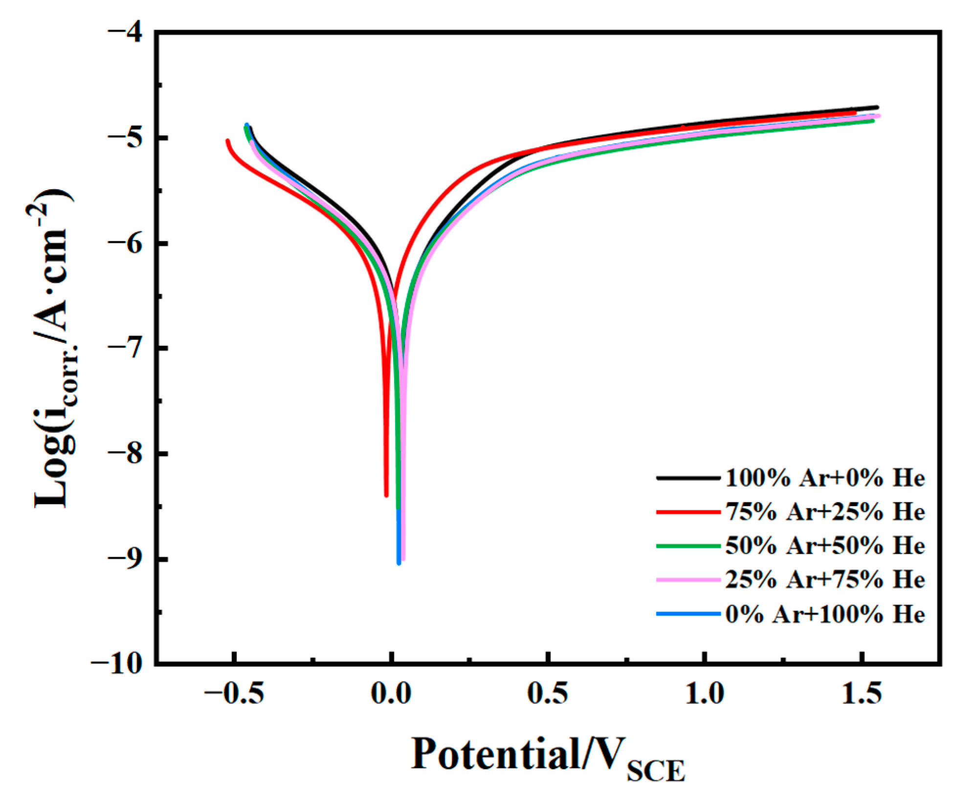
3.4.1. Electrochemical Polarization Curves of Welded Joints under Different Shielding Gases

The dynamic potential polarization curves are mainly divided into two regions: cathode and anode. As shown in Figure 14, the polarization curves of different protective gases under 3.5 wt.% NaCl solution has basically the same trend.
The joints went through an activated dissolution zone and a passivation zone, as observed by the anodic reaction process. The dissolution rate in the activated dissolution zone is controlled by the activated polarization. As the electrode potential increases, the current density gradually increases. When the electrode potential reaches a critical value, the metal surface will begin to passivate, forming a passivated coating with excellent corrosion resistance. The current density hardly changes at this stage, and the metal enters a stable passivation zone. Self-corrosion potentials ( E c o r r ) and self-corrosion current densities ( I c o r r ) were obtained by fitting polarisation curves using the Tafel extrapolation method. I c o r r reflects the corrosion rate, with smaller I c o r r indicating a slower corrosion rate [16]. E c o r r reflects the corrosion tendency, with a higher E c o r r indicating better protection of the generated passivated coating and lower corrosion tilt. 75% He protective gas has a minimum I c o r r of 3.90 × 10⁻⁷ A/cm2. 100% Ar protective gas has a maximum I c o r r of 4.92 × 10⁻⁷ A/cm2. The E c o r r is not significantly different for welded joints under different shielding gases. Comparison of TA2 laser–arc hybrid welded joints under different welding processes I c o r r and E c o r r revealed that the corrosion resistance strength of the welded joints obtained under different shielding gases was 75% He + 25% Ar > 100% He > 50% He + 50% Ar > 100% Ar > 25% He + 75% Ar.

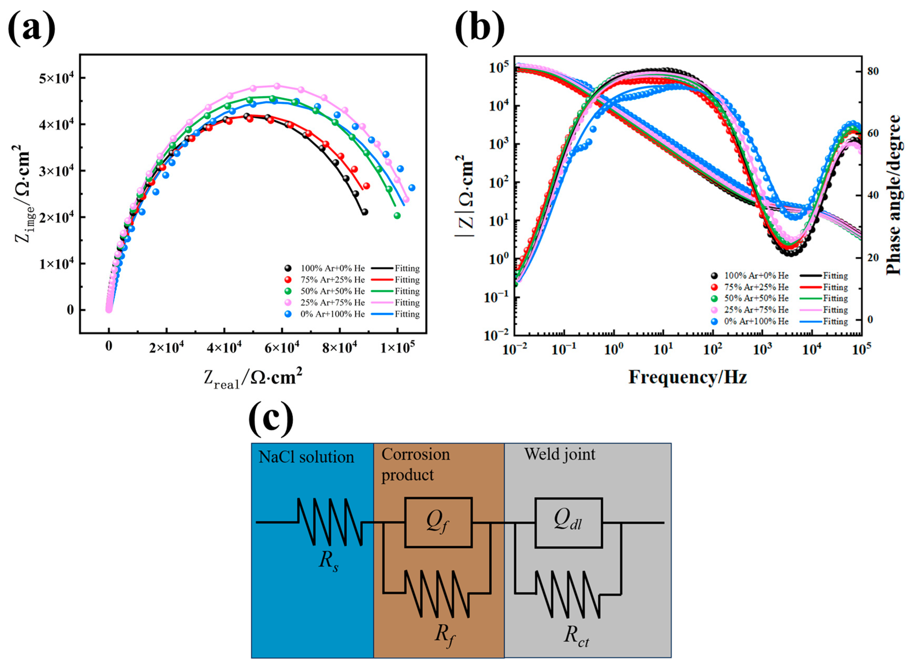
3.4.2. Electrochemical Impedance Spectra of Welded Joints under Different Shielding Gases

Figure 15 demonstrates the Nyquist plots of TA2 laser–arc hybrid welded joints in 3.5 wt.% NaCl solution. The electrochemical impedance spectra of the welded joints obtained with different helium contents of protection all exhibit semicircular capacitive arcs, and the overall characteristics of the capacitive arcs of the welded joints are similar with different protective gases, indicating a consistent corrosion reaction mechanism of the welded joints. However, when 75% helium shielding gas is used, the radius of arc resistance of the welded joints obtained increases significantly, while pure argon shielding gas is relatively small, and the difference between the two is more obvious. The size of the arc resistance radius reflects the strength of the reaction resistance in the corrosion process; the larger the radius, meaning that the more difficult electrochemical corrosion, the smaller the corrosion rate of the joint, the stronger the corrosion resistance of the joint. Therefore, the corrosion rate of the welded joints under 75% helium protection is smaller, and its corrosion resistance is better than that of the welded joints under pure argon protection, which is consistent with the analysis results of the kinetic potential polarization curve.
The impedance spectral curve shown in Figure 15a,b was fitted using ZSimpWin v3.60 Using the R(QR)(QR) model as the equivalent circuit for the fitting procedure, as shown in Figure 15c In the equivalent circuit, R s represents the solution resistance and Q f is the membrane capacitance formed by the corrosion product R f refers to the resistance of the corrosion product, Q d l is the double-layer capacitance, and R c t represents the resistance associated with the charge transfer process. The n f and n c t are the capacitance deviation factors (0 ≤ n ≤ 1); when n tends to 1, the passivation film on the surface of the metal electrode is more uniform and better formed. The fitting results are shown in Table 7.
As shown in Table 7, the polarization resistance of the welded joints protected by 75% helium is much larger than that of the pure argon welded joints, indicating that the welded joints protected by 75% helium are superior in terms of corrosion resistance, which is consistent with the conclusion obtained from the polarization curve analysis.

4. Conclusions

Comparative experiments were carried out in the TA2 pure titanium laser–arc hybrid welding process using different ratios of helium–argon gas mixtures as shielding gases, aiming to analyze the changes in the hybrid plasma properties and arc characteristics during the welding process under different shielding gases. The results of the study are as follows:
(1)
The increase in the helium ratio leads to the increase of gas ionization energy, and the arc is gradually contracted due to the difference in the physical properties of the two gases, thus increasing the arc heat flow density. When the helium volume share reaches 50%, the arc width reaches the minimum value, and the arc column width is compressed from 6.96 mm to 2.61 mm, which is 63% compression, and the heat flow density reaches the peak value. When the helium volume continues to increase beyond 50%, the arc height begins to decrease while the arc width increases. When the proportion of helium exceeds 75%, the arc burning becomes difficult, and even the arc quenching phenomenon occurs;
(2)
As the proportion of helium in the shielding gas increases, the stability of the arc improves, which leads to a significant reduction in spatter on the weld surface and a significant improvement in the quality of the weld formation. However, when welding with 100% helium shielding gas, the arc burns with difficulty, arc quenching occurs frequently, and the weld surface becomes uneven. The addition of helium to the shielding gas significantly improved the porosity defects in the welded joints, and the rate of weld porosity defects was reduced to about 0.42% when pure helium shielding was applied, which was about 86% lower compared to 3.02% under pure argon shielding. Therefore, helium can effectively inhibit weld porosity defects and improve the stability of locking holes;
(3)
Comparison of the weld grain size of welded joints under pure argon protection and welded joints under high purity helium protection revealed that due to the increase in heat input, the cooling rate of the welded joints was slowed down, resulting in full growth of the α’ phase in the weld and an increase in the grain size in the center of the weld. The results of tensile tests showed that the strength of the welded joints under mixed shielding gas was slightly lower than that of the joints under pure argon protection; different gases have little impact on the tensile properties of the welded joints;
(4)
The welded joints all showed similar passivation in a 3.5 wt.% NaCl solution environment. The tendency of corrosion resistance of welded joints to increase and then decrease with the increase in the proportion of helium in the shielding gas, reaching a maximum at a helium percentage of 75%, was attributed to the reduction of porosity in the weld and the change in the density of grain boundaries in the welded joints, which led to the difference in corrosion resistance.

Author Contributions

Conceptualization, H.Z. and M.S.; methodology, M.S. and Z.C.; software, M.S. and J.Y.; validation, M.S. and Q.Z.; formal analysis, M.S., Z.C. and X.T.; investigation, M.S. and X.T.; resources, J.Y. and Q.Z.; data curation, H.Z. and M.S.; writing—original draft preparation, M.S.; writing—review and editing, H.Z. and Q.Z.; visualization, M.S. and X.T.; supervision, H.Z. and Q.Z.; project administration, Q.Z. and J.Y.; funding acquisition, Q.Z. and J.Y. All authors have read and agreed to the published version of the manuscript.

Funding

The research was supported by the Innovative Research Group Project of the National Natural Science Foundation of China [grant number U22A20199].

Data Availability Statement

The original contributions presented in the study are included in the article, further inquiries can be directed to the corresponding author.

Conflicts of Interest

The authors declare no conflicts of interest.

References

  1. Banerjee, D.; Williams, J. Perspectives on titanium science and technology. Acta Mater. 2013, 61, 844–879. [Google Scholar] [CrossRef]
  2. Cui, C.; Hu, B.; Zhao, L.; Liu, S. Titanium alloy production technology, market prospects and industry development. Mater. Des. 2011, 32, 1684–1691. [Google Scholar] [CrossRef]
  3. Li, R.; Li, Z.; Zhu, Y.; Rong, L. A comparative study of laser beam welding and laser–MIG hybrid welding of Ti–Al–Zr–Fe titanium alloy. Mater. Sci. Eng. A 2011, 528, 1138–1142. [Google Scholar] [CrossRef]
  4. Su, R.; Li, H.; Chen, H.; Wang, H.; Wang, W.; Wang, D.; Guo, J. Stability analysis and porosity inhibition mechanism of oscillating laser-arc hybrid welding process for medium-thick plate TC4 titanium alloy. Opt. Laser Technol. 2024, 174, 110569. [Google Scholar] [CrossRef]
  5. Zhang, K.; Lei, Z.; Chen, Y.; Liu, M.; Liu, Y. Microstructure characteristics and mechanical properties of laser-TIG hybrid welded dissimilar joints of Ti–22Al–27Nb and TA15. Opt. Laser Technol. 2015, 73, 139–145. [Google Scholar] [CrossRef]
  6. Zhou, X.; Zhao, H.; Liu, F.; Yang, B.; Chen, B.; Tan, C. Influence of energy ratio on microstructure and mechanical properties in the transition zone of hybrid laser-MIG welded AH36/316L dissimilar joints. J. Mater. Res. Technol. 2021, 15, 4487–4501. [Google Scholar] [CrossRef]
  7. Bunaziv, I.; Akselsen, O.M.; Frostevarg, J.; Kaplan, A.F.H. Laser-arc hybrid welding of thick HSLA steel. J. Mater. Process. Technol. 2018, 259, 75–87. [Google Scholar] [CrossRef]
  8. Zhong, Y.; Zheng, Z.; Li, J.; Wang, C.; Wang, X. Effects of Ar-N2-He shielding gas on microstructure, mechanical properties and corrosion resistance of the Laser-MIG additive manufacturing 316L stainless steel. J. Mater. Process. Technol. 2023, 312, 117844. [Google Scholar] [CrossRef]
  9. Chen, H.; Tianli, Z.; Zhu, Z.; Xu, L.; Lin, S.; Yang, S.; Kou, S. Study on the effect of Ar–He shielding gas on the weld formation, microstructure and mechanical properties of 5083 aluminum alloy weld. J. Mater. Res. Technol. 2024, 28, 683–694. [Google Scholar] [CrossRef]
  10. Murphy, A.B.; Tanaka, M.; Tashiro, S.; Sato, T.; Lowke, J.J. A computational investigation of the effectiveness of different shielding gas mixtures for arc welding. J. Phys. D Appl. Phys. 2009, 42, 115205. [Google Scholar] [CrossRef]
  11. Zhu, Y.; Cai, Y.; Wang, M. Effects of He content in shielding gases on high-efficient hybrid laser arc welding with C-276 filler metal. J. Mater. Process. Technol. 2022, 299, 117367. [Google Scholar] [CrossRef]
  12. Lei, Z.; Li, Y.; Chen, Y.; Sun, Z.; Zhang, Y. Effect of process parameters on porosity formation ratio in dual-beam laser welding of aluminum alloys with filler wire. Hanjie Xuebao/Trans. China Weld. Inst. 2013, 34, 40–44. [Google Scholar]
  13. Li, D.; Yang, D.; Luo, X.; Zhang, G. Effects of shielding gas on GMAW of 10Ni5CrMoV HSLA steel using high Cr-Ni austenitic wire. J. Mater. Process. Technol. 2018, 259, 116–125. [Google Scholar] [CrossRef]
  14. Chae, H.-B.; Kim, C.-H.; Kim, J.-H.; Rhee, S. The effect of shielding gas composition in CO2 laser—Gas metal arc hybrid welding. Proc. Inst. Mech. Eng. Part B J. Eng. Manuf. 2008, 222, 1315–1324. [Google Scholar] [CrossRef]
  15. Liu, W.; Wang, H.P.; Lu, F.; Cui, H.C.; Tang, X.H. Investigation on effects of process parameters on porosity in dissimilar Al alloy lap fillet welds. Int. J. Adv. Manuf. Technol. 2015, 81, 843–849. [Google Scholar] [CrossRef]
  16. Li, H.; Zou, J.S.; Yao, J.S.; Peng, H.P. The effect of TIG welding techniques on microstructure, properties and porosity of the welded joint of 2219 aluminum alloy. J. Alloys Compd. 2017, 727, 531–539. [Google Scholar] [CrossRef]
  17. Hosseini Motlagh, N.S.; Parvin, P.; Jandaghi, M.; Torkamany, M. The influence of different volume ratios of He and Ar in shielding gas mixture on the power waste parameters for Nd:YAG and CO2 laser welding. Opt. Laser Technol. 2013, 54, 191–198. [Google Scholar] [CrossRef]
  18. Valiente Bermejo, M.A.; Karlsson, L.; Svensson, L.E.; Hurtig, K.; Rasmuson, H.; Frodigh, M.; Bengtsson, P. Effect of shielding gas on welding performance and properties of duplex and superduplex stainless steel welds. Weld. World 2015, 59, 239–249. [Google Scholar] [CrossRef]
  19. Cai, X.; Fan, C.; Lin, S.; Ji, X.; Yang, C.; Guo, W. Effects of shielding gas composition on arc properties and wire melting characteristics in narrow gap MAG welding. J. Mater. Process. Technol. 2017, 244, 225–230. [Google Scholar] [CrossRef]
  20. Cai, C.; He, S.; Chen, H.; Zhang, W. The influences of Ar-He shielding gas mixture on welding characteristics of fiber laser-MIG hybrid welding of aluminum alloy. Opt. Laser Technol. 2019, 113, 37–45. [Google Scholar] [CrossRef]
  21. ISO 5817:2022; Welding—Fusion-Welded Joints in Steel, Nickel, Titanium and Their Alloys (Beam Welding Excluded)—Quality Levels for Imperfections. ISO: Geneva, Switzerland, 2023.
  22. Ahn, J.; He, E.; Chen, L.; Dear, J.; Davies, C. The effect of Ar and He shielding gas on fibre laser weld shape and microstructure in AA 2024-T3. J. Manuf. Process. 2017, 29, 62–73. [Google Scholar] [CrossRef]
  23. Yu, J.; Cai, C.; Xie, J.; Chen, Z.; Chen, H. Keyhole stability, arc behavior, and molten pool flow in narrow-gap oscillating laser-arc hybrid welding of titanium alloy. Int. J. Heat Mass Transf. 2024, 220, 124922. [Google Scholar] [CrossRef]
  24. Wang, Y.; Liu, W.; Li, W.; Su, X.; Zhao, W.; Xu, G.; Zhu, J. Effects of He-Ar shielding gas compositions on arc plasma physical properties in rotating laser + GMAW hybrid fillet welding: Numerical simulation. Opt. Laser Technol. 2024, 178, 111231. [Google Scholar] [CrossRef]
  25. De Freitas Teixeira, P.R.; De Araújo, D.B.; Da Cunha, L.a.B. Study of the Gaussian distribution heat source model applied to numerical thermal simulations of TIG welding processes. Ciência Eng. Sci. Eng. 2014, 23, 115–122. [Google Scholar] [CrossRef]
  26. Lu, W.; Shi, Y.; Lei, Y.; Li, X. Effect of electron beam welding on the microstructures and mechanical properties of thick TC4-DT alloy. Mater. Des. 2012, 34, 509–515. [Google Scholar] [CrossRef]
  27. Murphy, A.B. The effects of metal vapour in arc welding. J. Phys. D Appl. Phys. 2010, 43, 434001. [Google Scholar] [CrossRef]
Figure 1. Welding experiment schematic diagram and sampling schematic diagram: (a) Metallographic specimen; (b) electrochemical test specimen; (c) tensile test specimen; (d) slicing plane.
Metals 14 00946 g001
Figure 2. Plasma images of different shielding gas laser–arc hybrid welding: (a) 100%Ar; (b) 75%Ar + 25%He; (c) 50%Ar + 50%He; (d) 25%Ar + 75%He; (e) 100%He.
Metals 14 00946 g002
Figure 3. The influence of different He contents on the morphology of arc: (a) 100%Ar; (b) 75%Ar + 25%He; (c) 50%Ar + 50%He; (d) 25%Ar + 75%He; (e) 100%He.
Metals 14 00946 g003
Figure 4. Effect of different He contents on arc width: (a) Width diagram; (b) arc width.
Metals 14 00946 g004
Figure 5. Effect of different He content on arc shape: (a) 100%Ar; (b) 75%Ar + 25%He; (c) 50%Ar + 50%He; (d) 25%Ar + 75%He; (e) 100%He.
Metals 14 00946 g005
Figure 6. The distribution of arc heat flux density under different shielding gases.
Metals 14 00946 g006
Figure 7. Characteristics of laser–arc hybrid weld formation under different shielding gases: (a) 100%Ar; (b) 75%Ar + 25%He; (c) 50%Ar + 50%He; (d) 25%Ar + 75%He; (e) 100%He.
Metals 14 00946 g007
Figure 8. Weld joint cross-sectional morphology: (a) 100%Ar; (b) 75%Ar + 25%He; (c) 50%Ar + 50%He; (d) 25%Ar + 75%He; (e) 100%He.
Metals 14 00946 g008
Figure 9. The influence of helium content on weld cross-section.
Metals 14 00946 g009
Figure 10. Comparison of the microstructure of argon and helium welded joints: (a) argon arc zone; (b) argon laser zone; (c) helium arc zone; (d) helium laser zone.
Metals 14 00946 g010
Figure 11. Pore distribution of welded joints under different shielding gases.
Metals 14 00946 g011
Figure 12. Tensile curves of welded joints under different shielding gases.
Metals 14 00946 g012
Figure 13. Macroscopic morphology of tensile specimen.
Metals 14 00946 g013
Figure 14. Dynamic potential polarization curves of welded joints under different shielding gas.
Metals 14 00946 g014
Figure 15. EIS curves of welded joints under different shielding gas and fitted equivalent circuit diagrams: (a) Nyquist curve; (b) Bode curve; (c) fitted equivalent circuit diagrams.
Metals 14 00946 g015
Table 1. Chemical composition of commercially pure titanium TA2 (mass fraction/%).
GradeNCHFeOTi
TA20.0300.0800.0150.3000.250Bal.
Table 2. Welding experiment parameters.
ParametersValue
Laser power (W)6000
Arc current (A)150
Arc voltage (V)13.5
Stick out distance (mm)12
Welding speed (m/min)0.9
Wire feeding speed (m/min)8
Distance between heat sources (mm)3.5
Helium content0, 25%, 50%, 75%, 100%
Shielding gas flow rate (L/min)35
Table 3. Basic physical properties of Argon and Helium.
Gas TypeArgonHelium
Boiling point (1.013 bar)/°C−185.9−268.9
Densities (0 °C,1.01 bar)/kg/m31.7840.178
Thermal conductivity/W/(m·k)0.0170.154
Table 4. Ionization energy of elements (eV).
Ionization EnergyTiArHe
E16.8315.7524.58
E213.5727.6254.41
Table 5. Coefficient of heat flow concentration under different shielding gas.
Shielding Gases TypesCoefficient of Heat Source Concentration (k)
100%Ar0.25
75%Ar + 25%He0.67
50%Ar + 50%He1.75
25%Ar + 75%He1.68
100%He1.61
Table 6. Tensile test results of joints welded under different shielding gas.
SampleTensile Strength/MPaElongation/%Fracture Location
100%Ar37952Base metal
75%Ar + 25%He37256Base metal
50%Ar + 50%He37253Base metal
25%Ar + 75%He37757Base metal
100%He37455Base metal
Table 7. Electrochemical parameters of welded joints under different shielding gas.
Parameters0% He25% He50% He75% He100% He
R s /(Ω/cm2)1.4911.3041.1741.5881.279
Q f /(F/cm2)6.374 × 10−76.810 × 10−77.447 × 10−77.681 × 10−75.610 × 10⁻⁷
n f 0.9110.9740.8960.9681
R f /(Ω/cm2)17.3419.2518.2317.1117.35
Q d l /(F/cm2)2.684 × 10−53.048 × 10−52.629 × 10−52.162 × 10−51.904 × 10⁻⁵
n c t 0.9740.8810.9720.9000.853
R c t /(Ω/cm2)96,080101,500108,400113,200113,100
Disclaimer/Publisher’s Note: The statements, opinions and data contained in all publications are solely those of the individual author(s) and contributor(s) and not of MDPI and/or the editor(s). MDPI and/or the editor(s) disclaim responsibility for any injury to people or property resulting from any ideas, methods, instructions or products referred to in the content.

