Abstract
The continuous retained-mandrel rolling process is a promising method for titanium tube production with high efficiency and a short process. The importance of mandrel as a deformation tool supporting the inner wall is crucial. This paper thoroughly examines the influence of mandrel velocity on the deformation characteristics at the groove vertex using three approaches: numerical simulation, shear-deformation observation experiments, and microstructure analysis. The following conclusions are drawn: Decreasing the mandrel velocity enhances the penetration of shear deformation into the inner wall of the titanium tube, improves thickness uniformity, and shifts the deformation mechanism near the inner wall from twinning to dislocation slip. As a result, the volume fraction of recrystallization increases from 18.4% to 42.3%. However, the mean shear strain increases first and then decreases to a certain value as the mandrel speed decreases, which is attributed to the combined influence of the cross-shear zone and the rolling force.
1. Introduction
Titanium and titanium alloys are referred to as marine metals due to their high specific strength, long fatigue life, and strong corrosion resistance [1,2,3]. Conventional titanium alloys, which include alloying elements such as Al and V, have reduced corrosion resistance compared to pure titanium [4]. While adding precious metals like Ru and Pa improves corrosion resistance, the high cost of these elements limits their widespread use in pipeline systems. The commercially pure titanium tube is currently the most widely used seamless pipe among titanium and titanium alloys. Its relatively low cost and ease of cold bending make it the preferred material for marine seawater pipeline systems [5,6,7].
The current titanium tube production process primarily relies on hot extrusion, cold rolling (cold drawing), and annealing. In comparison, the hot continuous rolling process offers higher production efficiency, simpler procedures, lower energy consumption, and the ability to produce in multiple lengths [8]. This process uses rolls and mandrels as external and internal rolling tools to continuously adjust the outer diameter and wall thickness of the tube during hot deformation. The continuous retained-mandrel rolling process (CRR) is the most advanced hot continuous rolling technique, where the mandrel speed remains constant throughout the rolling process.
Therefore, the condition of the mandrel is crucial in the CRR process. For example, Li et al. [9] analyzed the temperature field and its variations at various stages of the rolling process. Sui et al. [10] established a finite element model for the fine quality mill to study the stress field during the mandrel’s service life. Additionally, there is an abundance of literature available on the condition of the mandrel during the hot continuous rolling process. Chernykhu et al. [11] investigated the effect of mandrel diameter on the shape and dimensional accuracy of the hollow shell. Li et al. [12] used numerical simulation to study the effects of mandrel diameter on stress, strain, and temperature fields during rolling and validated the model through experiments. Lan et al. [13] conducted a theoretical study using the strip element method to examine the effects of mandrel speed and friction on the rolling process. Zhou et al. [14] studied the impact of restricted-mandrel speed on the dimensional accuracy of a hollow shell and the axial force on the mandrel, concluding that increasing mandrel speed can reduce overfilling at the groove taper and improve the accuracy of tube wall thickness. Yin et al. [15] used a three-dimensional elastoplastic thermal-coupling finite element method to determine the effects of mandrel speed and friction coefficient on the force–energy parameters and deformation parameters during tube rolling.
However, previous studies on mandrel speed have primarily focused on its effect on the free zone and groove taper, with limited analysis of the deformation characteristics in the groove vertex area. The deformation state in this region is critical as it determines the microstructure and mechanical properties of the hollow tube. Therefore, this paper uses a combination of numerical simulation and experimental methods to investigate the rolling mechanism at different mandrel speeds. It provides a detailed analysis of the mesh deformation, cross-shear zone distribution, strain distribution, and force–energy parameters of pure titanium tubes. Additionally, a direct observation model is designed to observe deformation characteristics in the thickness direction, exploring the impact of mandrel speed on the microstructural evolution of pure titanium tubes.
2. Numerical Modeling of CRR Process
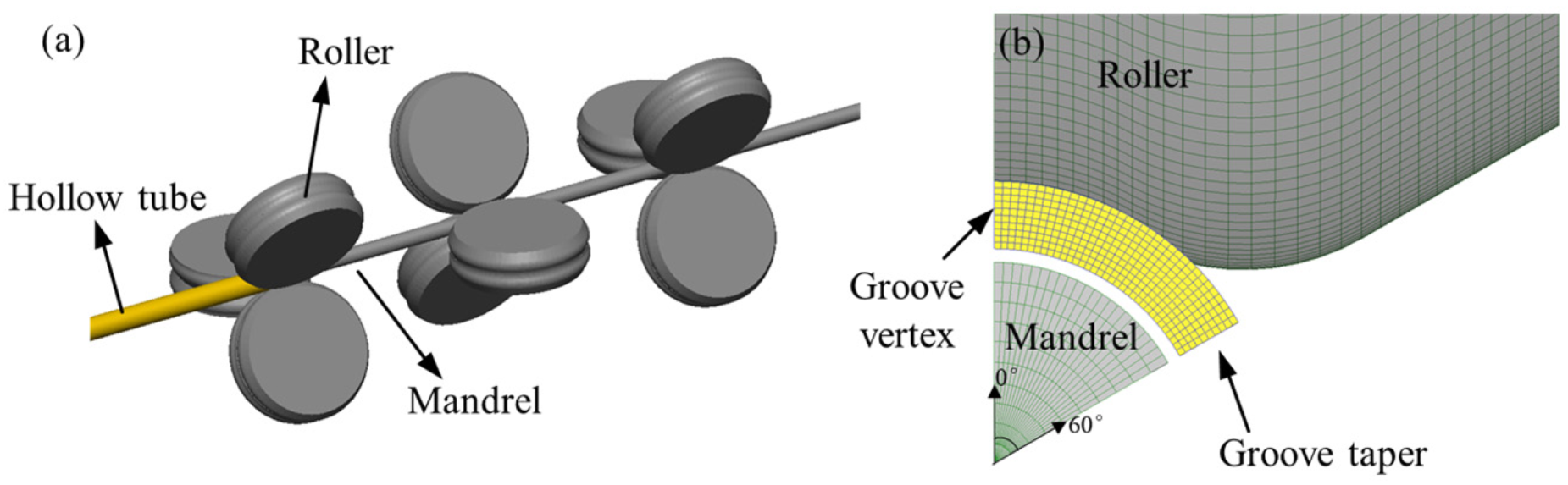
The finite element model of the CRR process consists of three sets of stands, each consisting of three identical rolls arranged 120° to each other with the rolling center line as the center, as shown in Figure 1a. In addition, the corresponding positions of the groove vertex and groove taper are shown in Figure 1b.
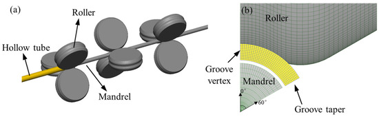
Figure 1.
The finite element model of the CRR process: (a) overall view, (b) local view.
The finite element model in this study was configured as follows:
- (1)
- Geometric model properties: The tube blank is set as a plastic body, and the roll and mandrel are considered to be rigid materials that only conduct heat due to their small elastic deformation.
- (2)
- Boundary conditions: Due to the symmetry in the rolling process, only one-sixth of the model was simulated to improve computational efficiency. Symmetry constraints were applied at the symmetrical cross-section of the tube.
- (3)
- Friction conditions: Coulomb friction was selected as the friction model for the rolling simulation, with the friction coefficient assumed to remain constant during the CRR process. The friction coefficient between the rollers and the tube was set to 0.45, while the mandrel, lubricated with a water-based graphite lubricant before rolling, had a friction coefficient of 0.1 [16,17].
- (4)
- Heat transfer conditions: At an ambient temperature of 20 °C, the contact heat transfer coefficient between the tube and the rollers/mandrel was set to 30 kW/m2K. The heat convection coefficient between the tube and the air was 0.02 kW/m2K. The heat transfer coefficients due to frictional deformation and plastic deformation were set to 0.7 and 0.9, respectively [18,19].
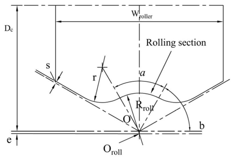
Figure 2 shows a schematic diagram of the rolling groove, and the parameters of the CRR process are listed in Table 1. The mandrel speeds were set at 140 mm/s, 190 mm/s, 240 mm/s, 290 mm/s, and 340 mm/s. The selection of the rolling temperature is based on reference [20].
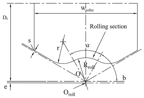
Figure 2.
Schematic diagram of the rolling groove.

Table 1.
The specific parameters of the CRR process.
3. CRR Experiments
In this experiment, a commercially pure titanium tube of grade II was used, with a composition of C-0.08%, Fe-0.25 wt%, H-0.025 wt%, N-0.03 wt%, O-0.05 wt%, and balance Ti and dimensions of Φ50 mm × 6 mm. The initial microstructure of the titanium tube is shown in Figure 3. Figure 3a presents the optical microstructure (OM) of the tube billet before rolling, where the grains are equiaxed, reflecting the typical annealed microstructure without twinning. Figure 3b,c show the EBSD inverse pole figure (EBSD-IPF) and pole figure of the tube billet, respectively. It can be observed that the c-axes of most grains are tilted from the transverse direction (TD) towards the normal direction (ND), indicating a noticeable rotated transverse texture. The samples for microscopic inspection were taken from the rolling plane (RD-ND) of the tube billet and the rolled tube. After polishing and corrosion, the samples were observed under Leica DMi8 optical microscopy (Leica Microsystems, Wetzlar, Germany). The samples after electrolytic polishing were subjected to EBSD detection under a Thermo Fisher Scientific scanning electron microscope (Thermo Fisher Scientific, Waltham, MA, USA) equipped with an EDAX detector (AMETEK EDAX Inc, Pleasanton, CA, USA). The acceleration voltage and working distance were set to 20 kV and 15 mm, respectively, to collect crystallographic information with a step size of 0.5 μm. Subsequently, the microstructure characteristics were analyzed using OIM software (version of 7.2).
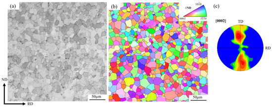
Figure 3.
Tube billet initial microstructure: (a) OM map, (b) EBSD-IPF map, (c) pole figure.
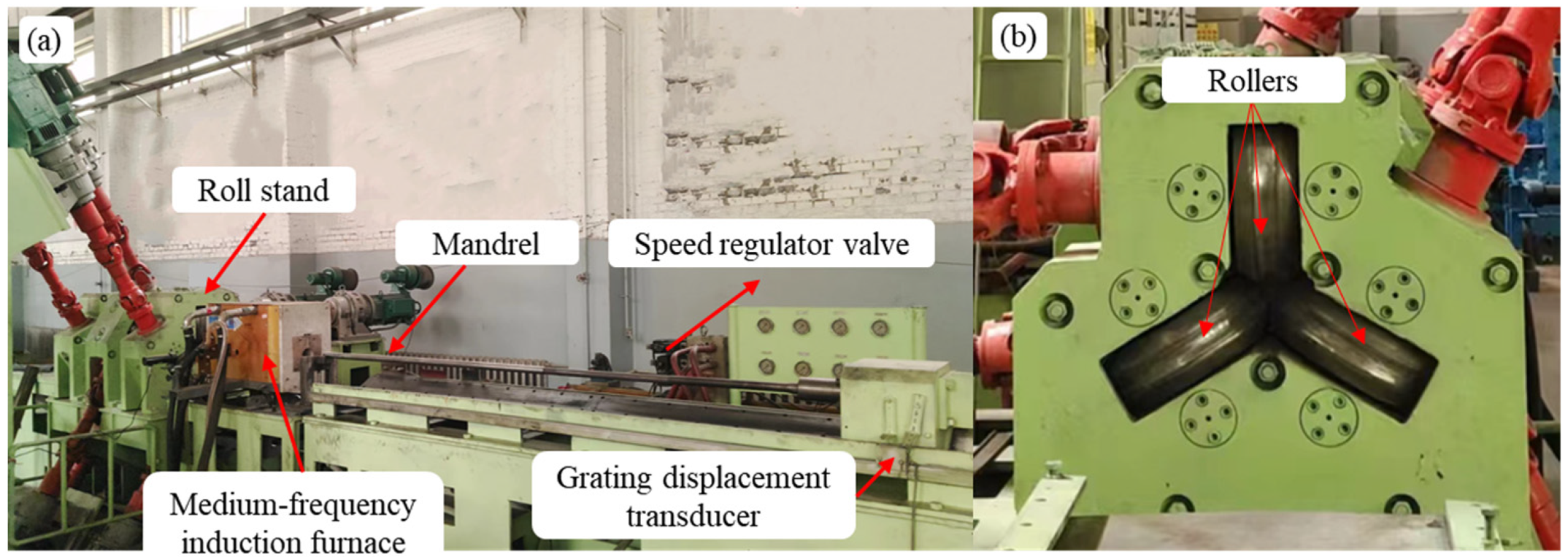
The titanium tubes were experimentally tested using a continuous retained-mandrel rolling mill developed by the research group. Figure 4a shows an overall view of the rolling mill, where the mandrel is driven by a hydraulic cart. The speed of the mandrel can be manually adjusted via a regulator valve, and the cart is equipped with a grating displacement transducer. After calculation by a plc program, the mandrel speed can be computed in real time, enabling precise control of the mandrel speed. The induction heating furnace heats the titanium tubes online, reducing heat loss during the insertion of the mandrel and the transfer of the tube to the rolling mill. Figure 4b shows a rear view of the rolling mill, illustrating that the rollers are arranged at an angle of 120 degrees to each other and are driven by three separate DC motors. Additionally, to reduce speed fluctuations of the three motors under load within the same stand, a motor-speed synchronization control program was incorporated into the motor control system.
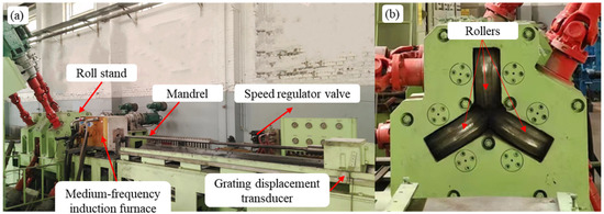
Figure 4.
Continuous retained-mandrel rolling mill: (a) front view, (b) rear view.
To better observe the distribution of shear deformation in the thickness direction, a direct macroscopic observation model was designed, following the method used for observing deformation in asymmetric rolling, which involves internal metal implantation [21]. To prepare the sample for this design, a 1 mm hole was first punched through the tube billet. A titanium wire (indicated by the arrow) was then cut to the thickness of the tube, as shown in Figure 5a. This wire was inserted into the tube billet with a transitional fit, as illustrated in Figure 5b. Figure 5c shows the inserted tube sample. Finally, rolling experiments with various mandrel speeds were conducted at a reduction ratio of 30%, as excessive reduction rates would make it difficult to distinguish the implanted wire from the matrix.
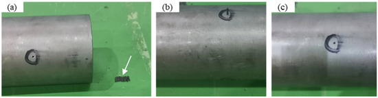
Figure 5.
Samples directly observed for shear deformation of tube rolling: (a) perforated tube billet and wire, (b) tube sample during inserting, (c) tube sample inserted.
4. Results and Discussion
4.1. Mesh Deformation
Figure 6 illustrates the influence of mandrel speed on the mesh geometry at the groove vertex of the tube under different reduction ratios. During rolling, the tube first makes contact with the roll. Due to the frictional force from the roll, the mesh is partially elongated along the rolling direction. As rolling progresses, the tube contacts the mandrel due to plastic bending. When rolling with a fast mandrel (340 mm/s), the inner wall of the tube experiences minimal elongation while the outer wall undergoes significant elongation, resulting in a mesh deformation similar to the horizontal projectile motion curve in physics when the tube is rolled out. In contrast, when rolling with a slow mandrel (140 mm/s), the mesh in the thickness direction is inclined at a uniform angle as the rolling progresses. As deformation continues, the skew of the mesh increases, and ultimately, the mesh becomes a straight line at a steep angle. This deformation indicates that slow mandrel rolling allows the deformation to penetrate more effectively into the inner wall of the tube. As the reduction radio increases, the overall shear deformation increases during slow mandrel rolling, while the mesh elongation on the inner wall of the tube remains minimal under fast mandrel rolling. This suggests that although increasing the reduction ratio intensifies the degree of deformation in the tube under different mandrel speeds, it does not alter the rolling deformation state of the tube. Therefore, to facilitate analysis, the subsequent wall reduction rate is fixed at 30%.
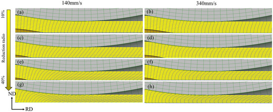
Figure 6.
The mesh geometry at the groove vertex under mandrel velocities of (a,c,e,g) 140 mm/s and (b,d,f,h) 340 mm/s to a reduction ratio of (a,b) 10%, (c,d) 20%, (e,f) 30%, and (g,h) 40%.
4.2. Cross-Shear Zone
The speed difference between the roll and the mandrel in the CRR process inevitably leads to the formation of a cross-shear zone, which plays a crucial role in shear strain, rolling force, and grain refinement during rolling [22]. Figure 7 shows the positions of the neutral points of the roll and the mandrel (indicated by the arrows), as well as the cross-shear zone of the tube under different mandrel speeds. It can be observed that as the mandrel speed decreases, the neutral point on the mandrel side continuously shifts towards the rolling entrance, while the neutral point of the roll shows no significant change. This differs somewhat from asymmetric rolling in plate materials due to the low friction coefficient between the mandrel and the tube, which prevents deformation on the inner wall of the tube from effectively penetrating the outer wall. When the mandrel speed is 190 mm/s, the neutral point of the mandrel no longer lies within the rolling deformation zone; in other words, from the rolling entrance to the neutral point of the roll, the titanium tube remains in the cross-shear zone, with the zone size reaching 17.41 mm at this point. Furthermore, as the mandrel speed continues to decrease, the neutral point on the roll side does not move towards the exit, so the width of the cross-shear zone remains unchanged.
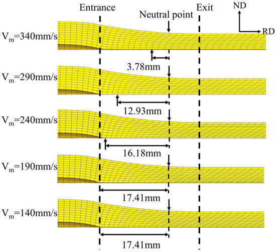
Figure 7.
Neutral point position and cross-shear zone at different mandrel speeds.
4.3. Strain Distribution
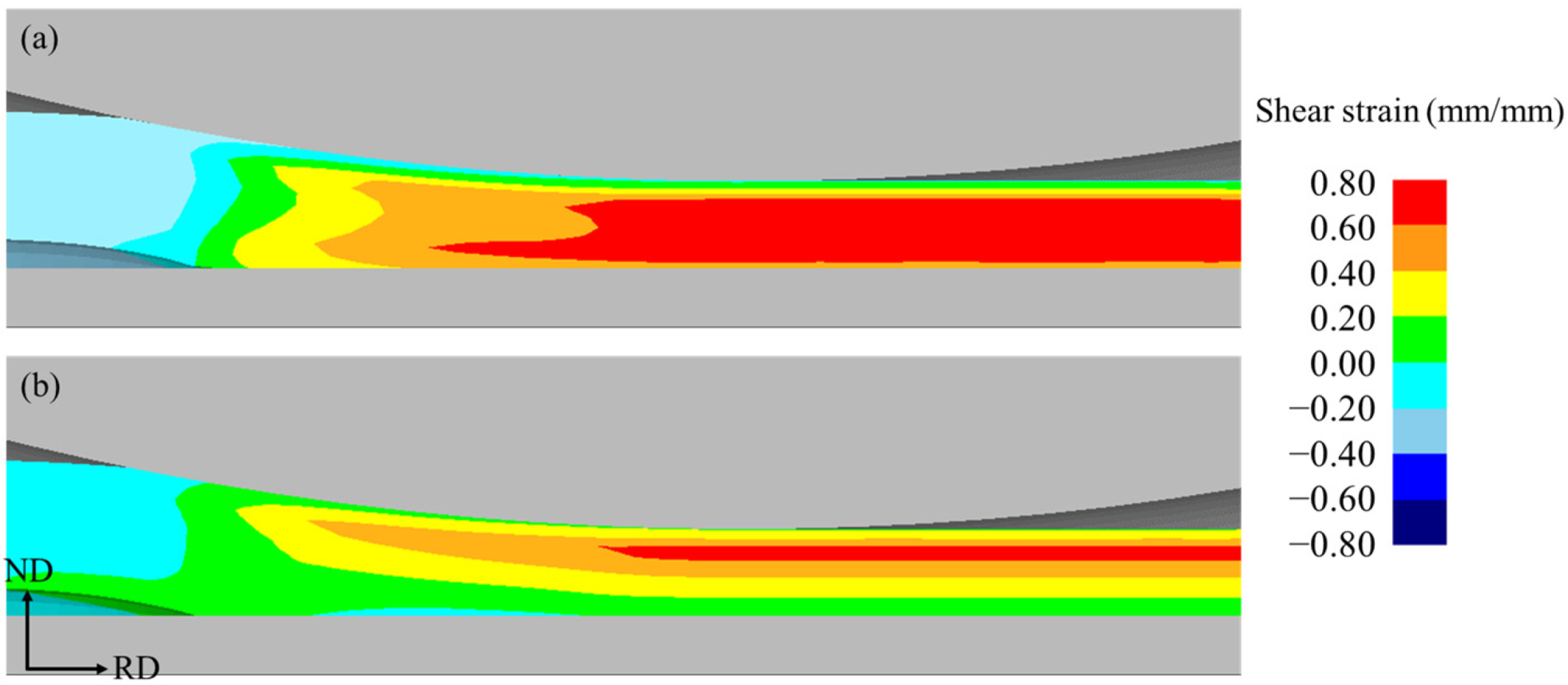
Some studies have indicated that shear deformation is a primary factor in grain refinement [23,24]. In this paper, shear strain is used as the evaluation criterion to investigate the effect of hot rolling deformation on grain refinement in tubes. Figure 8 presents the shear strain distribution at the groove vertex of the tube under different mandrel speeds during the rolling process. It is observed that the shear strain on the inner and outer surfaces is lower compared to the central layer. This finding aligns with Serajzadeh’s research on hot-rolled strips [25], which suggests that temperature differences result in less mesh distortion on the inner and outer walls compared to the central layer. Additionally, under slow mandrel conditions, shear strain is uniformly distributed across the thickness direction of the tube, whereas, under fast mandrel conditions, the shear strain is predominantly concentrated on the outer wall, which is consistent with the observed mesh deformation pattern.

Figure 8.
Shear strain distribution at the groove vertex under different mandrel speeds: (a) 140 mm/s, (b) 340 mm/s.
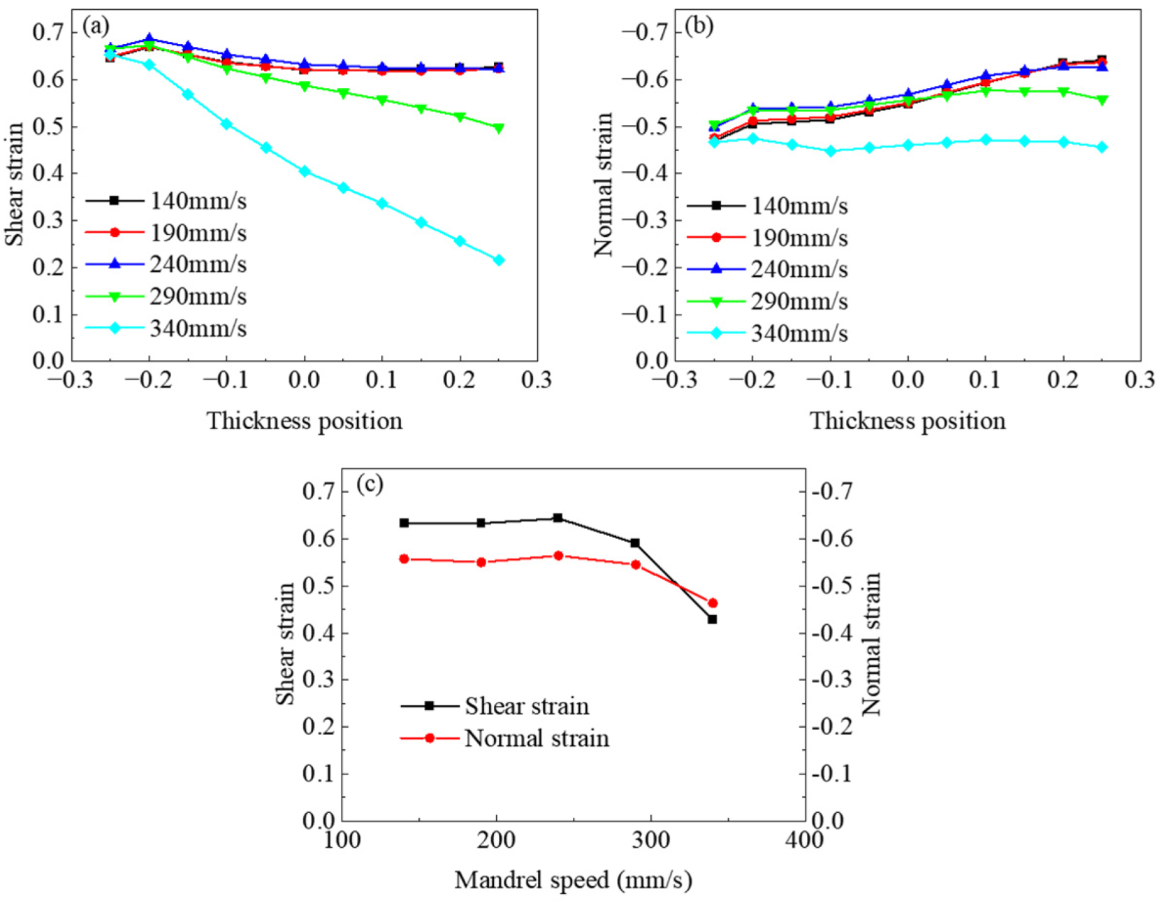
To more effectively describe the influence of mandrel velocity on strain distribution in the thickness direction, the position within the tube’s thickness was normalized using the formula , where S represents the tube wall thickness and h is the thickness at the specific location. In this normalization, m = −0.5 corresponds to the outer wall of the tube (roll side), while m = 0.5 indicates the inner wall of the tube (mandrel side).
To avoid the influence of surface-chilling effects, the region selected for studying the effect of mandrel speed on strain at the groove vertex was constrained to −0.25 (near the inner wall) < m < 0.25 (near the outer wall), as shown in Figure 8. When the mandrel speed is 340 mm/s, the shear strain is concentrated on the outer wall side and gradually decreases along the thickness direction, reaching 0.21 near the inner wall. This results in a non-uniform distribution of shear strain in the thickness direction of the tube. In contrast, at slower mandrel speeds, the shear strain distribution in the thickness direction of the tube is relatively uniform, with the inner-wall shear strain averaging around 0.63. Regarding radial compressive strain, the mandrel speed has little to no effect on it.
Interestingly, the maximum shear strain in the rolled tube is not achieved at the lowest mandrel speed. As shown in Figure 9c, the maximum average shear strain occurs at a mandrel speed of 240 mm/s. When the mandrel speed exceeds this value, the average shear strain gradually decreases due to the lower shear strain on the inner side of the tube. Conversely, when the speed drops below this value, the shear strain decreases to a certain level and then remains constant. Studies by Kim et al. [26,27] also found that an optimal shear texture in AZ31 magnesium alloy sheets is achieved when the roll diameter ratio is 1.5. The reason for this phenomenon is that a reduction in mandrel speed enlarges the cross-shear zone, which promotes increased shear deformation, leading to a rise in shear strain. However, with a further decrease in mandrel speed, the rolling pressure during tube rolling decreases. According to the Coulomb law of friction, this results in a decrease in friction between the tube and the rolls, thereby suppressing the cross-shear effect and reducing the shear strain. Notably, when the mandrel speed drops from 340 mm/s to 240 mm/s, the effect of the cross-shear zone on enhancing shear strain outweighs the suppressive effect of reduced rolling pressure. However, when the mandrel speed falls below 240 mm/s, the friction reduction caused by lower rolling pressure becomes the dominant factor. Additionally, when the mandrel speed decreases from 190 mm/s to 140 mm/s, the cross-shear zone expands to cover the entire deformation area. Further reduction in mandrel speed does not increase the cross-shear zone; hence, the shear strain remains unchanged.
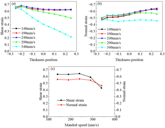
Figure 9.
Effect of mandrel velocity on strain distribution at groove vertex: (a) shear strain, (b) normal strain, (c) mean value.
4.4. Force–Energy Parameters
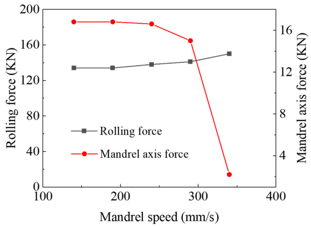
Due to the influence of rolling pressure and the cross-shear zone, a reduction in mandrel speed does not lead to a continuous increase in shear strain; in fact, shear strain may even increase as the mandrel speed decreases. To further demonstrate the changes in rolling force, Figure 10 illustrates the variations in rolling pressure and the axial force of the mandrel at different mandrel speeds. It can be observed that when the mandrel speed increases from 140 mm/s to 190 mm/s, the rolling pressure does not significantly change because the proportion of the cross-shear zone remains constant. However, when the mandrel speed increases to 340 mm/s, the proportion of the cross-shear zone decreases, leading to a gradual increase in rolling force, reaching a maximum value of 151 kN. As the mandrel speed continues to increase, the axial force of the mandrel first remains unchanged and then gradually decreases, reaching a minimum value of 0.22 kN at a mandrel speed of 340 mm/s. Therefore, an excessively low mandrel speed results in increased axial force, which can shorten the mandrel’s service life, while a reduction in rolling force also reduces shear strain. On the other hand, an excessively high mandrel speed can decrease the axial force of the mandrel, but the deformation imposed by the roll has difficulty penetrating the inner wall of the tube billet. Thus, maintaining the mandrel speed at 240 mm/s achieves the best balance between these factors.
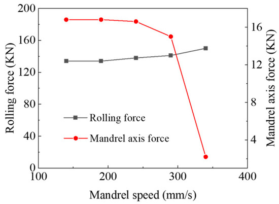
Figure 10.
Rolling force and axial force of mandrel at different mandrel speeds.
4.5. Macroscopic Observation of Shear Deformation
In order to better quantify the impact of mandrel speed on the shear deformation of titanium tubes, this study uses the angle between the deformed wire after rolling and the normal direction of the tube to represent the degree of shear deformation, which is referred to as the shear angle. The schematic diagram of this shear angle is shown in Figure 11 below.
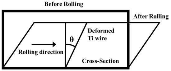
Figure 11.
Shear angle diagram.
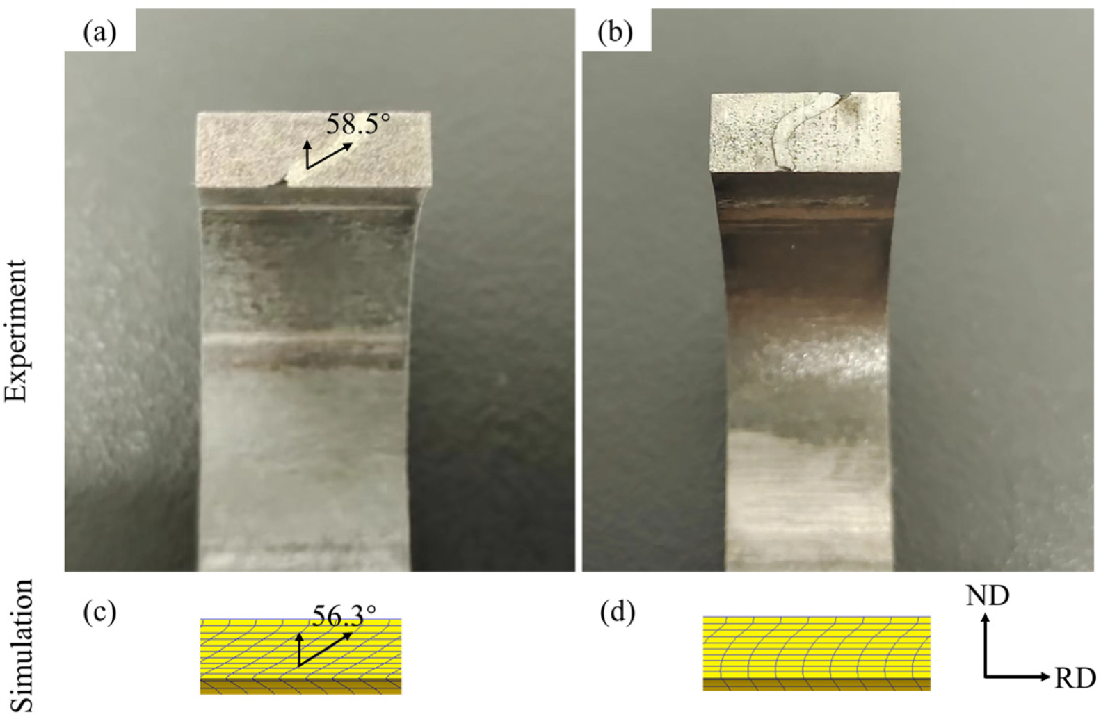
Figure 12 shows the deformation state of the wire in the ND-RD surface after rolling at different mandrel speeds. The deformation of the inserted wire in the direction of the entire thickness of the tube can be clearly seen. When the mandrel speed is 340 mm/s, the shape of the inserted wire is similar to the horizontal projectile motion curve, and the inclination degree of the wire decreases gradually from the outer wall to the inner wall, where the wire at the inner wall is almost not inclined, indicating that the shear deformation degree at the inner wall is low when the mandrel speed is high. When the mandrel speed is 140 mm/s, the shape of the inserted wire can be regarded as a straight line tilted from the ND to the RD, indicating that the tube has strong shear deformation in the entire thickness direction. In addition, compared with the results of the finite element simulation and experiment, it can be seen that the deformation degree of the finite element mesh is almost the same as that of the inserted wire in the experiment. The average shear angle of the finite element mesh and the implanted wire in the slow mandrel rolling is 56.3° and 58.5°, respectively. The error is less than 4%, indicating that the simulation results are highly reliable.
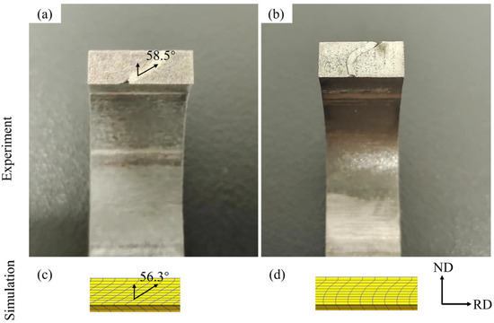
Figure 12.
Comparison of finite element method and experimental results of tube macroscopic deformation at different mandrel speeds: (a,c) 140 mm/s, (b,d) 340 mm/s.
In order to measure the inclination angle of the inserted wire more accurately, a rectangular coordinate system with the RD as the X-axis and the ND as the Y-axis was established, and a point was taken along the thickness direction of the wire at a distance of 0.1 mm to measure its value. Figure 13 shows the distribution of the shear angle along the thickness direction, and the position of the point is taken from the near outer wall to the near inner wall. It can be found that the shear angle of the slow mandrel rolling along the thickness direction is almost greater than that of the fast mandrel rolling, but there is an exception on the near outer wall side. When the mandrel speed is 140 mm/s, the shear angle from the near outer wall to the near inner wall first increases to a certain value and then remains unchanged, while when the mandrel speed is 340 mm/s, the shear angle first decreases to 4.2° and then rises. The last rise in the shear angle may be caused by incomplete lubrication of the mandrel during actual operation.
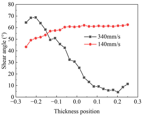
Figure 13.
Thickness distribution of shear angle of inserted wire at different mandrel speeds.
4.6. Microstructure
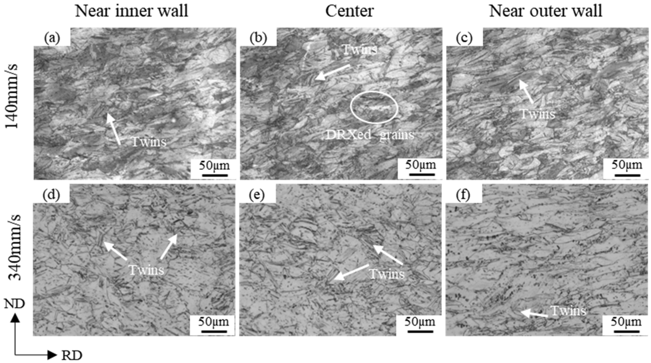
Due to the differences in deformation characteristics, changes in mandrel speed inevitably affect the distribution of the microstructure in the rolled tube. Figure 14 shows the microstructural characteristics of the near outer wall, center, and near inner wall at the groove vertex. When the mandrel speed is 340 mm/s, there is a significant variation in the microstructure along the thickness direction of the tube. The number of twins gradually decreases from the inner wall to the outer wall, with the grains near the outer wall being noticeably stretched along a direction that is radially deflected by 65° towards the axial direction. This deflection angle is similar to the shear angle observed in shear deformation. However, the grains in the central and near inner wall regions exhibit a lower degree of deformation. This is because the friction coefficient of the roll, which is larger than that of the relatively lubricated mandrel, provides greater shear force to the outer surface of the tube, and the higher mandrel speed also hinders deformation penetration along the thickness direction. When the mandrel speed is 140 mm/s, the grains near the inner wall, center, and outer wall are all stretched axially and compressed radially, indicating that the deformation at the groove vertex is not only borne by the outer wall but also penetrates to the inner wall side of the tube. This results in more uniform deformation across the thickness direction, with the final grains deflecting by approximately 60° from the radial direction towards the axial direction, an angle similar to the shear angle observed in the macroscopic shear analysis.
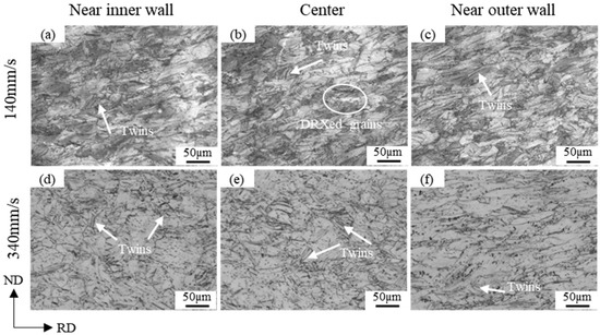
Figure 14.
Microstructure of titanium tube thickness direction at mandrel velocities of 340 mm/s and 140 mm/s: (a,d) near inner wall; (b,e) center; (c,f) near outer wall.
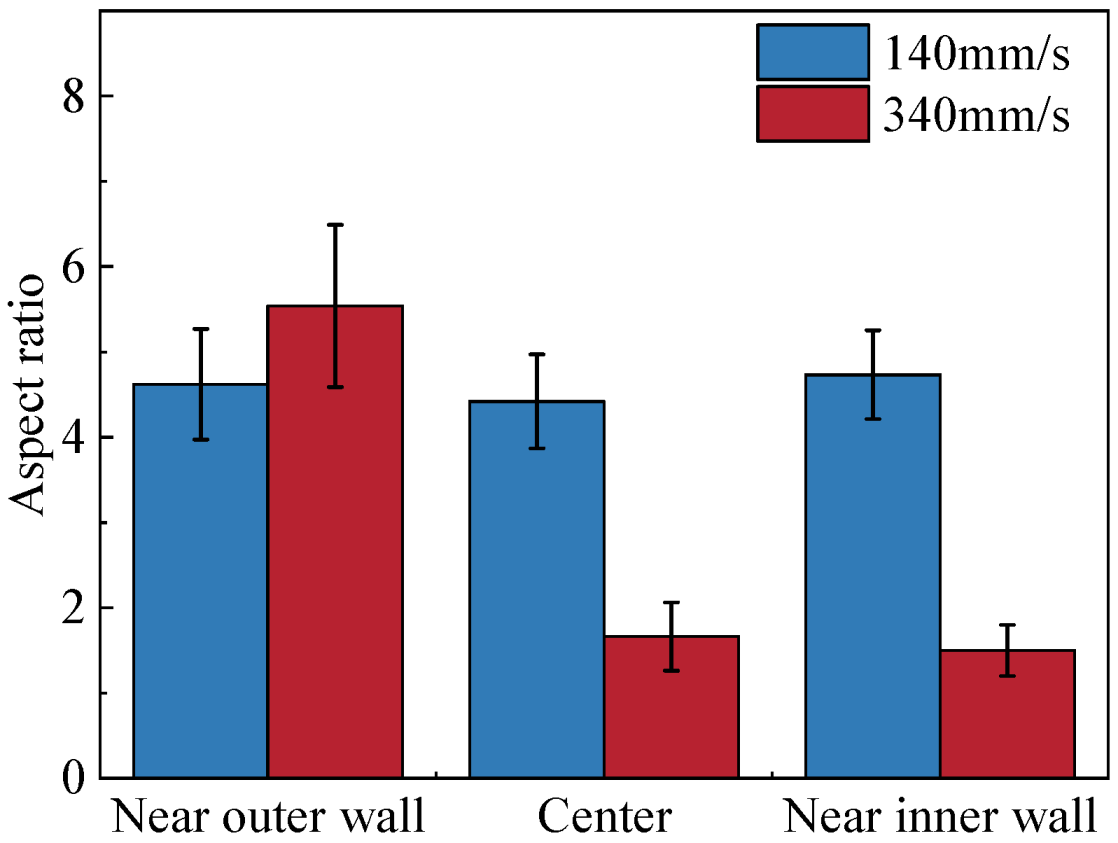
Figure 15 illustrates the quantitative evolution of the grain aspect ratio (the ratio of the long axis to the short axis) in the thickness direction at the groove vertex under different mandrel speeds. When the mandrel speed is 340 mm/s, the grain aspect ratio decreases from the near outer wall to the near inner wall. However, during slow mandrel rolling, the grain aspect ratio of the titanium tube is uniformly distributed across the thickness direction. Additionally, the grain aspect ratio at the outer surface of the titanium tube after fast mandrel rolling is 5.54, which is slightly higher than the grain aspect ratio of 4.62 under slow mandrel rolling. However, considering the entire thickness direction, the average grain aspect ratio under the fast mandrel process is lower than that under the slow mandrel process. This suggests that the slow mandrel process results in a more uniform microstructure at the groove vertex of the rolled tube, which means more stable mechanical properties, so it is recommended to appropriately reduce the mandrel speed in industry production.
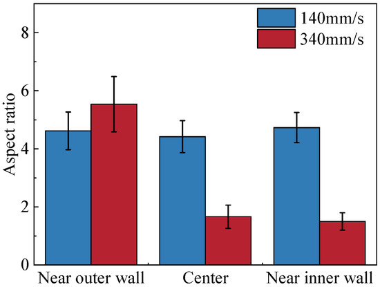
Figure 15.
Evolution of grain axial ratio in thickness direction with mandrel speed.
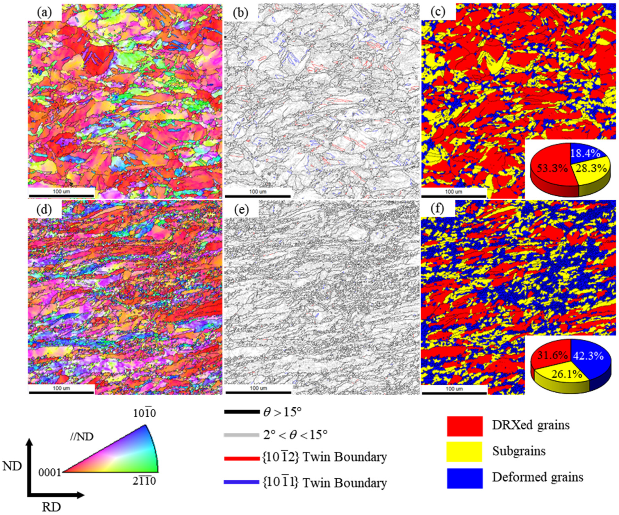
To obtain a higher volume fraction of recrystallized grains, rolling experiments were conducted at a 40% reduction ratio. Figure 16 presents the orientation imaging analysis of the near inner wall of the titanium tube after rolling at 750 °C under different mandrel speeds. Figure 16a,d display the EBSD inverse pole figures (EBSD-IPF), while Figure 16b,e show the grain boundary maps. In these maps, low-angle grain boundaries (LAGBs, 2°–15°) are indicated by gray lines, and high-angle grain boundaries (HAGBs, >15°) are represented by black lines. The tensile twins and compressive twins are marked in red and blue, respectively. The grain orientation spread (GOS) method was employed to statistically analyze the volume fraction of dynamic recrystallization (DRX). The minimum angle was defined to categorize the grains into recrystallized grains (2°), subgrains (5°), and deformed grains [28], which correspond to the blue, yellow, and red regions in Figure 16c,f, respectively.
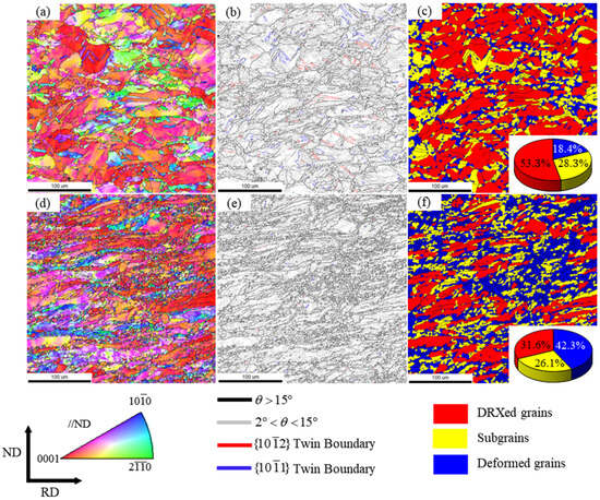
Figure 16.
The orientation imaging analysis of the near inner wall of the titanium tube under different mandrel speeds: (a–c) 340 mm/s, (d–f) 140 mm/s. (a,d) EBSD-IPF map, (b,e) GB map, (c,f) GOS map.
Comparing the EBSD-IPF and GOS maps, it can be observed that the deformed grains are predominantly red, indicating that they mainly exhibit a basal texture. In contrast, the recrystallized grains are represented by colors other than red, suggesting a certain angular deviation in orientation between the recrystallized grains and the matrix. Additionally, due to the high stacking-fault energy of titanium, the recrystallization mechanism here is primarily continuous dynamic recrystallization. Furthermore, through the quantitative analysis of twins under rapid mandrel rolling conditions (Figure 16b), it was found that only the and twins are present during hot rolling, while the twins commonly seen in cold-rolled titanium sheets are absent. This absence is because twins are only activated when the processing temperature is below 300 °C and require a high level of stress for activation [29], whereas twins can be activated in the temperature range of 400 °C to 800 °C. In fact, the shear stress required to produce twins is relatively low, making them easier to activate. Interestingly, the volume fractions of the and twins generated in this study are nearly equal, influenced by the basal texture of the deformed grains after rolling. As the mandrel speed decreases, the proportion of dynamic recrystallized (DRXed) grains increases from 18.4% to 42.3%, while the proportion of deformed grains decreases from 53.2% to 31.6%. These results indicate that as the mandrel speed decreases, the deformation mechanism shifts from twinning to dislocation slip, resulting in the formation of a greater number of fine DRXed grains.
5. Conclusions
Through experimental and numerical analysis, the influence of mandrel speed on the continuous retained-mandrel rolling process of pure titanium tubes and their microstructure evolution mechanism was studied. The research results show the following conclusions:
- Under different mandrel diameter coefficients, the mandrel speed has a similar impact on the deformation state of the tube. During rapid mandrel rolling, the shear strain concentrates in the inner and outer layers of the tube, with the inner wall primarily undergoing compressive deformation. As the mandrel speed decreases, the shear strain becomes uniformly distributed in the thickness direction of the tube, allowing shear deformation to penetrate better into the inner wall. At a mandrel diameter coefficient of 0.3, the shear strain at the inner wall can reach 0.63.
- As the mandrel speed decreases, the shear strain at the groove vertex first continuously increases and then decreases to a stable value, reaching a maximum at a speed of 240 mm/s. The increase in shear strain is mainly due to the enlargement of the rolling zone, while the subsequent decrease is attributed to the reduction in rolling force, which diminishes the friction between the roll and the outer surface of the tube, thereby weakening the rolling effect. Furthermore, the shear strain cannot continue to decrease due to limitations in the rolling zone area.
- A macroscopic shear-deformation observation experiment was designed in the tube for the first time. During slow mandrel rolling, the shear angle of the implanted material was 58.5°, uniformly distributed in the thickness direction, which is close to the numerical simulation result of 56.3°.
- As the mandrel speed decreases, the microstructure at the groove vertex of the titanium tube becomes more uniform in the thickness direction. The generated and twins gradually disappear, indicating that the main deformation mechanism shifts from twinning to dislocation slip. The volume fraction of recrystallization gradually increases from 18.4% to 42.3%.
Author Contributions
Conceptualization, T.W. and C.L.; methodology, C.L.; software, J.C.; validation, J.C. and Y.S.; formal analysis, J.C.; writing—original draft preparation, C.L.; writing—review and editing, Y.S.; visualization, T.W.; funding acquisition, Y.S. All authors have read and agreed to the published version of the manuscript.
Funding
This work was supported by the Major Science and Technology Projects of Shanxi Province (20191102009) and the Key R&D Projects of Shanxi Province (201903D121049).
Data Availability Statement
The original contributions presented in the study are included in the article, further inquiries can be directed to the corresponding author.
Conflicts of Interest
The authors declare that they have no known competing financial interests or personal relationships that could have appeared to influence the work reported in this paper.
References
- Wang, C.P.; Wang, H.Z.; Ruan, G.L.; Wang, S.H.; Xiao, Y.X.; Jiang, L.D. Applications and prospects of titanium and its alloys in seawater desalination industry. IOP Conf. Ser. Mater. Sci. Eng. 2019, 688, 033036. [Google Scholar] [CrossRef]
- Gorynin, I.V.; Oryshchenko, A.S.; Leonov, V.P.; Mikhailov, V.I.; Schastlivaia, I.A. Titanium Application in Marine Engineering and Nuclear-Power Engineering. In Proceedings of the 13th World Conference on Titanium; John Wiley & Sons, Inc.: Hoboken, NJ, USA, 2016. [Google Scholar]
- Schutz, R.W.; Watkins, H.B. Recent developments in titanium alloy application in the energy industry. Mater. Sci. Eng. A 1998, 243, 305–315. [Google Scholar] [CrossRef]
- Chao, Q.; Sabirov, I.; Guo, T.; Hodgson, P.D.; Beladi, H. Tailoring the deformation characteristics of commercial purity titanium through hot deformation of a martensitic microstructure. Mater. Sci. Eng. A 2021, 827, 142075. [Google Scholar] [CrossRef]
- Oryshchenko, A.; Leonov, V.; Mikhailov, V.; Kuznetsov, P.; Alexandrov, A. Titanium in shipbuilding and other technical applications. MATEC Web Conf. 2020, 321, 02001. [Google Scholar] [CrossRef]
- Song, D.J.; Niu, L.; Yang, S.L. Research on Application Technology of Titanium Alloy in Marine Pipeline. Rare Met. Mater. Eng. 2020, 49, 1100–11040. [Google Scholar]
- Titanium Information Group. Titanium for Offshore and Marine Applications: A Designers and Users Handbook; National Metals Technology Centre Ltd.: Rotherham, UK, 2006. [Google Scholar]
- Wang, C.F.; Xue, J.G.; Zhou, Z.Y.; Ji, B.; Wu, Y.Y.; Zhang, C.X.; Sun, H.M. A preliminary discussion on Making Ti-alloy OCTG by using the floationg-Mandril method. Non-Ferr. Min. Metall. 2015, 31, 34–36. [Google Scholar]
- Li, X.W.; Dong, B. Finite element analysis of temperature field of PQF mandrel. Baosteel Technol. 2016, 54–59. [Google Scholar] [CrossRef]
- Pang, N.; Zhan, Z.Y. Simulation of Stress Field During Φ159 mm FQM Mandrel Service Process. Hot Work. Technol. 2015, 44, 138–141. [Google Scholar]
- Chernykh, I.N.; Shendyapin, K.V.; Game, E.A. Studying the Effect of the Mandrel Diameter on the Quality of Pipes Produced by Longitudinal Rolling. Metallurgist 2021, 65, 147–152. [Google Scholar] [CrossRef]
- Li, C.; Yuanhua, S.; Chen, J.; Zhou, Y.; Dong, B.; Wang, C.; Chen, C.; Yujun, G. Research on the impact of mandrels in titanium tubes during tube continuous rolling. Mater. Res. Express 2023, 10, 086512. [Google Scholar] [CrossRef]
- Lan, X.C.; Liu, H.M. Effect of mandrel moving speed and mandrel friction on continuous seamless-tube rolling process. Iron Steel 1994, 29, 28–33. [Google Scholar]
- Zhou, Z.P. Finite Element Analysis of Effect on Pierced Billet Dimensional Accuracy by Retained Mandrel Speed of MPM Pipe Mill. Steel Pipe 2020, 49, 4. [Google Scholar]
- Yin, Y.D.; Li, S.Z. 3D finite element analysis of effect of mandrel on continuous seamless tube rolling process. Heavy Mach. 2005, 1, 40–43. [Google Scholar]
- Takahashi, K.; Inoue, T.; Uchida, S. Characteristics of hot friction in commercially pure titanium. Nippon. Steel Tech. Rep. Overseas 2002, 85, 41–46. [Google Scholar]
- Wang, H.; Xu, B.; Liu, J. Micro and Nano Sulfide Solid Lubrication; Springer: Berlin/Heidelberg, Germany, 2012. [Google Scholar]
- Nemat-Nasser, S.; Guo, W.-G.; Nesterenko, V.F.; Indrakanti, S.; Gu, Y.-B. Dynamic response of conventional and hot isostatically pressed Ti–6Al–4V alloys: Experiments and modeling. Mech. Mater. 2001, 33, 425–439. [Google Scholar] [CrossRef]
- Yoshida, M. 3D FEM simulation of rolling load working on piercer plug in mannesmann piercing process. AIP Conf. Proc. 2010, 1252, 1333–1338. [Google Scholar]
- Thota, M.K.; Kapoor, R.; Basak, C.B.; Mukherjee, A.B.; Chakravartty, J.K. High temperature deformation of α-Ti. Mater. Sci. Eng. A 2015, 624, 213–219. [Google Scholar] [CrossRef]
- Dhinwal, S.S.; Toth, L.S.; Lapovok, R.; Hodgson, P.D. Tailoring one-pass asymmetric rolling of extra low carbon steel for shear texture and recrystallization. Materials 2019, 12, 1935. [Google Scholar] [CrossRef]
- Tang, D.L.; Liu, X.H. Geometric parameters in cross shear zone of asymmetrical rolling. Iron Steel 2015, 50, 34–39. [Google Scholar] [CrossRef]
- Dobatkin, S.; Galkin, S.; Estrin, Y.; Serebryany, V.; Diez, M.; Martynenko, N.; Lukyanova, E.; Perezhogin, V. Grain refinement, texture, and mechanical properties of a magnesium alloy after radial-shear rolling. J. Alloys Compd. 2019, 774, 969–979. [Google Scholar] [CrossRef]
- Wang, L.; Fan, X.G.; Zhan, M.; Jiang, X.Q.; Liang, Y.F.; Zheng, H.J.; Liang, W.J. Revisiting the lamellar globularization behavior of a two-phase titanium alloy from the perspective of deformation modes. J. Mater. Process. Technol. 2021, 289, 116963. [Google Scholar] [CrossRef]
- Serajzadeh, S.; Taheri, A.K.; Nejati, M.; Izadi, J.; Fattahi, M. An investigation on strain inhomogeneity in hot strip rolling process. J. Mater. Process. Technol. 2002, 128, 88–99. [Google Scholar] [CrossRef]
- Kim, K.H.; Lee, D.N. Analysis of deformation textures of asymmetrically rolled aluminum sheets. Acta Mater. 2001, 49, 2583–2595. [Google Scholar] [CrossRef]
- Kim, S.H.; You, B.S.; Yim, C.D.; Seo, Y.M. Texture and microstructure changes in asymmetrically hot rolled AZ31 magnesium alloy sheets. Mater. Lett. 2005, 59, 3876–3880. [Google Scholar] [CrossRef]
- Chen, X.; Tang, B.; Liu, D.; Wei, B.; Zhu, L.; Liu, R.; Kou, H.; Li, J. Dynamic recrystallization and hot processing map of Ti-48Al-2Cr-2Nb alloy during the hot deformation. Mater. Charact. 2021, 179, 111332. [Google Scholar]
- Zeng, Z.; Jonsson, S.; Roven, H.J. The effects of deformation conditions on microstructure and texture of commercially pure Ti. Acta Mater. 2009, 57, 5822–5833. [Google Scholar]


Disclaimer/Publisher’s Note: The statements, opinions and data contained in all publications are solely those of the individual author(s) and contributor(s) and not of MDPI and/or the editor(s). MDPI and/or the editor(s) disclaim responsibility for any injury to people or property resulting from any ideas, methods, instructions or products referred to in the content. |
© 2024 by the authors. Licensee MDPI, Basel, Switzerland. This article is an open access article distributed under the terms and conditions of the Creative Commons Attribution (CC BY) license (https://creativecommons.org/licenses/by/4.0/).