Article

Laser Cladding Path Planning for Curved Metal Parts

1
School of Mechanical Engineering, Anhui Polytechnic University, Wuhu 241000, China
2
Wuhu Institute of Technology, Wuhu 241003, China
*
Author to whom correspondence should be addressed.
Metals 2024, 14(9), 1055; https://doi.org/10.3390/met14091055
Submission received: 28 July 2024 / Revised: 2 September 2024 / Accepted: 9 September 2024 / Published: 16 September 2024

Abstract

:
In depositing multiple layers on the surface of failed metal parts, the overlap rate is a critical factor in determining the surface smoothness and uniformity of the coating thickness. Therefore, special attention must be given to the spacing between adjacent melt tracks when planning laser paths on complex metal parts. A strategy for selecting the overlap rate for multi-track cladding is proposed, based on the key parameters of surface curvature, mass conservation, and the profile of single-track coatings. A multi-track overlap model is developed, expressing the relationship between coating morphology and the overlap rate. The optimal spacing value is determined to achieve the goal of high-quality coating remanufacturing. To verify the effectiveness of this method, nickel-based powder was used for laser forming on the surface of metal gears. The results showed that the surface of the cladding layer was smooth and flat, further demonstrating that this model helps improve the repair quality and overall performance of curved metal parts. Thus, it provides valuable guidance for the remanufacturing of failed metal parts.

1. Introduction

In laser additive manufacturing, the geometric shapes of failed components are highly diverse. Beyond common regular-shaped parts, complex contoured parts—comprising combinations of flat surfaces, small curved surfaces, and surfaces with significant curvature variations—are increasingly prevalent. The complexity in size and structure undoubtedly poses challenges to the repair process of high-value components. Addressing these challenges requires not only studying process parameters, powder systems, and performance evaluations but also developing a reasonable laser scanning path [1,2,3].
In the field of laser additive manufacturing, the planning of laser cladding paths for complex contoured parts is currently achieved through several methods:
(1). Utilizing Computer Numerical Control (CNC) Trajectory Planning. Amaia Calleja et al. employed CNC trajectory planning software to implement laser cladding path planning on a conical surface, offering new insights for surface remanufacturing technology [4]. Hamed Kalami et al. proposed two methods for toolpath generation: one for five-axis toolpaths and another for 2+1+1-axis toolpaths. Simultaneously, they developed rotational toolpaths to address the challenge of collision detection during tool operation [5]. Chang et al. developed a path planning model for blade components, studying the effects of Z-axis offset and rotational angle on the deposition results to improve the cladding quality [6]. This method does not incorporate laser process parameters.
(2). Formulating Surface Machining Path Equations. Feng et al. derived a relationship between the laser beam’s motion trajectory and the shaft journal’s relative velocity, allowing them to achieve the surface repair of crankshaft journals [7].
(3). Employing a Slicing Model for Path Generation [8,9]. Jin et al. established a fusion deposition model for surfaces with critical features, using a slicing method to improve coating surface evenness [10]. Huang et al. used point cloud data from parallel planes and contoured parts to determine intersections, approximating intersection points as laser scanning path points [11]. This method only studies the generation of a single path and belongs to the preprocessing work of establishing a multi-path overlap model.
(4). Equidistant Optimization Approach. Su et al. created a point cloud model for contoured surfaces and employed an equidistant approach to establish a set of processing path points. They searched for the next processing point in the vertical direction [12]. The approach works for parts with consistent curvature throughout, but it presents limitations when applied to contoured components.
(5). Application of Specialized Software. The SKM DCAM software is a CAM software specifically designed for the laser processing field, capable of handling STP format files. It enables three-dimensional laser processing based on the input part model by adjusting process parameters such as the laser power and feed rate to achieve trajectory filling [13]. Zheng et al. utilized computer technology to set process parameters within SLM path planning software, exporting the final data and transferring it to the processing equipment to complete the physical formation [14]. Starting from the forming principles of additive manufacturing systems, Xia developed a general-purpose additive manufacturing software platform. This platform includes methods such as fault-tolerant slicing and slice contour compensation, enabling the reuse of different additive processes within the same platform [15].
In addition, for large-sized parts, most scholars now improve coating quality by changing scanning strategies [16,17,18]. Rahman Rashid studied the influence of changing the scanning direction on coating microstructure, with results showing that longitudinal samples had higher plasticity and tensile strength [19]. Jenny Cecilia processed a titanium alloy surface using a unidirectional scanning method, enhancing the coating’s resistance to oxidation [20]. However, this method only applies to regular parts and cannot be extended to the remanufacturing of curved parts.
This paper presents a laser cladding path planning algorithm for contoured parts, considering processing parameters, surface characteristics, and coating profiles. It aims to enhance the precision of scanning path positions and orientations, achieving high-precision repairs on damaged components. The process begins by extracting flat segments from the STL model of the component’s repair area. Flat slices are created based on the cladding process parameters, allowing intersections with the component model. An algorithm is used to select viable path points, which are ranked according to practical processing requirements. In the relevant software, the actual processing path is simulated and then translated into a language that is recognizable by the robot. This program is ultimately integrated into the system for offline programming and robot control.

2. Mechanism of Multi-Track Lapping Forming

The shape and structure of metal parts are inherent attributes, obtained by processing the data from the coordinate measuring machine. For planar components, a fixed overlap rate is used for multi-track deposition. However, ensuring the forming quality becomes challenging when applied to curved metal components. Surface irregularities or the non-uniform thickness of the metal coating not only affect the uniform heating of the overall coating but also tend to induce residual stresses during the liquid-phase solidification, leading to crack formation and significantly reducing the mechanical properties of the metal coating [21,22,23]. On the other hand, during post-processing, numerical control technology is used to remove excess coating material to meet the dimensional requirements. Non-uniform coating thickness results in significant dimensional errors, necessitating rework, and increasing production costs. Therefore, two crucial factors for controlling the coating accuracy on curved components are the initial track and the spacing between adjacent tracks, as illustrated by laser processing parameters in Figure 1.
The changes in the molten pool profile under different process parameters exhibit a discernible pattern: the molten pool width increases with the increment in the laser power and powder feed rate. A greater quantity of powder equates to a higher absorption capacity for laser energy. However, when the powder feed rate becomes excessive, the powder consumes an excessive amount of laser energy during its descent, resulting in decreased laser energy acting on the metal substrate surface [24,25]. This, in turn, leads to a reduction in the dilution rate and a noticeable increase in the molten pool width. Figure 2 depicts the laser energy distribution, and the molten pool takes on a quasi-spherical shape after metal powder melting. This indicates that the laser energy gradually decreases from the center to the edges, with the color transitioning from red, through yellow and green, to blue. Measurements of the cross-sectional dimensions of a single track reveal that the molten pool radius does not significantly deviate from the beam radius.

2.1. Single-Track Model Analysis

The single-track coating contour model provides the theoretical foundation for laser scanning path planning. This model represents the powder deposition on the metal substrate surface, and it is considered a crucial factor influencing the uniformity of the overall cladding layer. In most of the literature, the regulation of the width and height of single-track coatings in the cross-section of the cladding layer is achieved by adjusting the powder feed rate, scanning speed, and laser power [26,27,28]. The most commonly employed models for single-track coating morphology include parabolic, circular arc, and elliptical models, with their corresponding functional relationships outlined as follows:
(1). Parabolic Model:
F i = a i x 2 + b i x + c i ,   F i ( x ) = 0 , ( x A i , B i ) , A i  
Ai and Bi represent the two endpoints of the width of the i-th track coating.
a 1 = 4 h / w 2 , b 1 = 4 h / w , c 1 = 0
(2). Circular Arc Model:
F i ( x ) = r i 2 ( x a i ) 2 b i , F i ( x ) = 0 , x A i , B i
(3). Elliptical Model:
F i ( x ) = b i · 1 x m i 2 / a i 2 , F i ( x ) = 0 , x A i , B i
The model with the smallest deviation from the actual single-track morphology is the parabolic model, followed by the circular arc model, while the fitting results for the elliptical model require improvement. In this article, a circular arc equation was selected to fit a single-track contour as the basis for investigating multi-track overlays. Several sets of different laser process parameters were configured on the laser cladding CNC platform and equipment for single-track cladding experiments. The metal coating cross-sectional width and height were measured under an industrial microscope, and the results are presented in Table 1. Using these data, the expression for the circular arc equation was derived, and curves were plotted in MATLAB 2021, as shown in Figure 3. A comparison was made, as illustrated in Figure 4, to assess the error between the circular arc model and the actual coating morphology. The red solid line represents the circular arc equation, and it can be observed that the equation provides a relatively good fit to the overall coating morphology. However, there is a certain gap at the contour’s edges due to the influence of the powder flow rate and external environmental factors during the actual cladding process. Small particles splattered during this process can adhere to the coating, causing surface irregularities. Although this phenomenon cannot be entirely avoided, it does not significantly impact the overall laser cladding forming process [29,30,31]. Therefore, this model can serve as the foundational theoretical model for describing the actual shape of the coating.

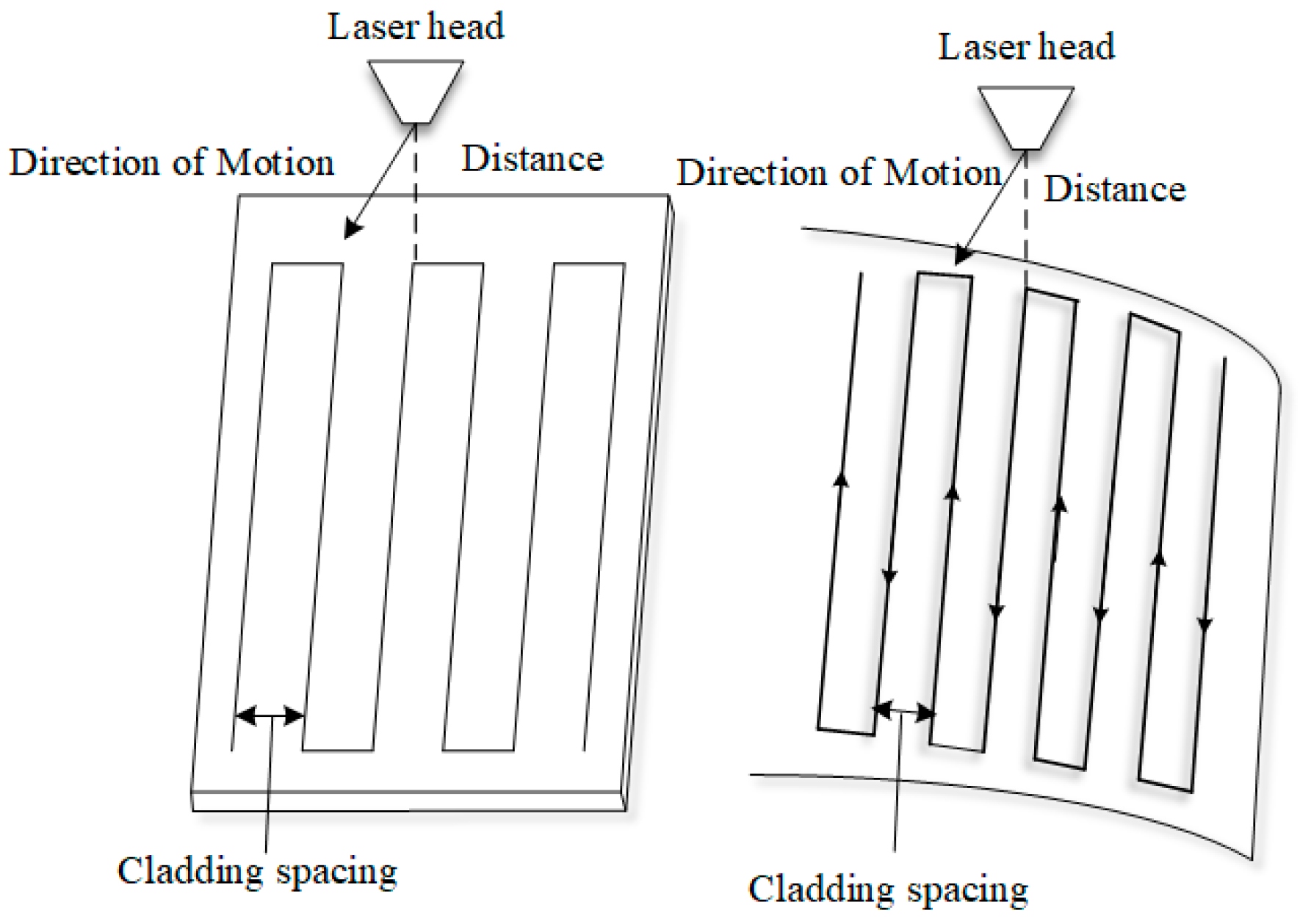
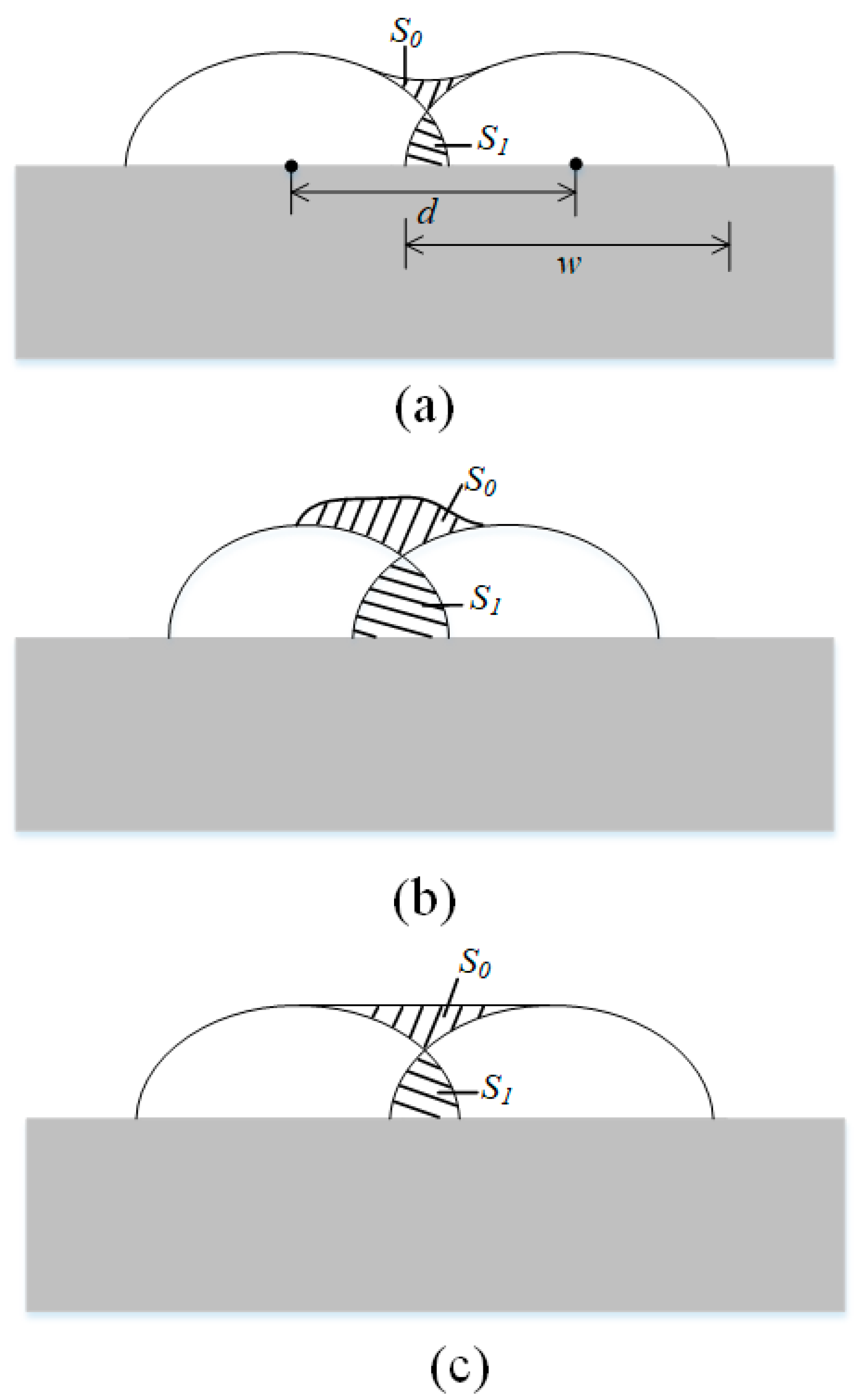
2.2. Establishment of a Multi-Pass Cladding Model

Building upon a single-track cladding contour, we analyze from the powder material mass conservation perspective, considering the mutual influence of process parameters and surface structure to establish a multi-track cladding model for curved components. To optimize the creation of cladding paths, certain assumptions need to be made before establishing the model:
Assumption 1: The relationship between the concentration distribution of the powder flow and the cross-sectional radius can be represented using a function.
Assumption 2: The phenomenon of powder spattering during the cladding process can be neglected.
Assumption 3: The powder’s material properties at various points within the laser irradiation direction perpendicular to the surface are the same, and the powder flow rate is equal at any cross-section.
Assumption 4: During the actual laser scanning process, external factors causing variations in the cross-sectional morphology of a single track can be ignored, i.e., the cladding layer width for each track is constant.
Under conditions where other process parameters are determined, setting different overlap rates will affect the forming quality of the cladding layer [32,33]. Figure 5 illustrates schematic representations of layer morphology for different overlap values. The theoretical overlap area is denoted as S 0 , and the actual overlap area is represented as S 1 . When adjacent cladding layers are too far apart, depressions appear on the coating’s surface. Conversely, when the adjacent cladding layers are too close, the coating surface tends to have protrusions. From this, it can be concluded that only an appropriate overlap ratio can ensure the smoothness of the metal coating.
In the case of processing flat objects (curvature = 0), the ideal overlap rate calculation is shown in Figure 6, where the coordinate origin represents the starting position of the first cladding layer, the horizontal axis is parallel to the plane, and the vertical axis is perpendicular to the plane. The width and height of a single-track cladding layer are denoted as w and h , respectively, while the width of the overlap region is d . Key point coordinates and the fitting equation for the single-track geometric morphology can be determined from this. the curvature radius R represents the extent of deviation from the horizontal plane at a given location. A larger curvature indicates that the overlapping area is similar to the flat state, whereas a smaller curvature signifies a more pronounced curvature of the surface. Changes in the overlapping area, whether it decreases or increases, lead to variations in heat transfer and convection characteristics within the melt pool. Curvature is an inherent property of the surface that cannot be adjusted. On a curved surface, there are differences in cladding spacing within different regions. To achieve optimal coating performance, starting from the perspective of a planar multi-track overlap model, a multi-track overlap model for the curved surface is established to determine the optimal trajectory spacing, as shown in Figure 7.
A rectangular coordinate system is established at the center of the coating, with the x-axis representing the direction of the line connecting the centers of adjacent tracks, and the y-axis pointing upward. S1, S2, S3 and S4 represent the areas of four different regions. Based on the laser cladding process requirements, it is evident that when S 1 = S 2 , the coating uniformity is maximized. Connecting the two vertices of the coating forms the line segment C 1 C 2 , with O 1 O 2 denoting the center of the circular arc. The intersection point M is a moving point on the coating profile and is equidistant from the centers of the two profiles, represented by A and B. The distance from the coating center to the intersection points of the adjacent coatings is denoted as “x”. We can see from the picture that
S 3 = 1 2 S 1
S 4 = 1 2 S 2
Then,
S 3 = S 4
S D M C 2 = S M Q B
x 0 [ f 1 f 2 ( x ) ] d x = Q x [ f 2 ( x ) f 3 ( x ) ] d x
Here, f1 represents the equation of line segment C1C2, f2 represents the equation of a single-track cladding layer profile, and f3 represents the profile curve equation. Based on the calculation process, the coordinates of intersection point M can be determined, allowing for the computation of the distance between adjacent coatings. The optimized trajectory spacing, denoted as δ, is based on numerical values in a two-dimensional coordinate system. To evaluate the accuracy of the model, the coefficient of determination (R2) was calculated to express the correlation between the predicted and actual values.
R 2 = 1 i = 1 n ( y i y ^ i ) 2 i = 1 n ( y i y ¯ i ) 2
where yi represents the actual value, y ^ i represents the model’s predicted value, and y ¯ i represents the actual mean value. For a circular part with a radius of 230 mm, the optimal overlap rate was calculated to be 35%. The distance between adjacent cladding layers was measured, and the average value obtained was 34.98. Substituting these values into the aforementioned formula resulted in an R2 value of 0.92. Since this value is close to 1, it indicates that the model has a good fit.
In practical processing, the laser moves in three-dimensional space, with the laser axis always aligned with the current path point’s normal vector. After completing laser cladding for a single track, it needs to rotate by a certain angle to reach the scanning position for the next track accurately. At this point, the corresponding rotation angle β is determined based on the optimized spacing value.
β = 2 a r c s i n ( δ 2 P )
According to mathematical model derivations and experimental data, factors influencing the cladding path on curved surfaces include the laser radius (r) and the radius of surface curvature (R). Curvature is an inherent property of the surface that cannot be adjusted. The laser radius is typically determined by the inherent characteristics of the laser source and the optical path transmission system. It is also related to the distance between the cladding head and the substrate surface during cladding. Therefore, controlling the beam spot radius within a certain range is advantageous for managing the laser energy density. There is a slight difference in the values of each device; for example, the spot diameter on the ZF-RFJC and ZF-CH005A systems produced by Shanghai Juyi Welding Co., Ltd. (Shanghai, China) are approximately 2 mm.
The vector control of processing points is a critical factor in ensuring the quality of the metal coating. Since there is a distance of τ between the laser head and the workpiece surface, the laser head’s orientation can be obtained from the path point P i along the normal vector n i :
S i = P i + τ n i n i
Here, S i represents the pose information of the laser head. The complete set of laser scanning path points is obtained S = {(xi,yi,zi,axi,ayi,azi), i = 1,2,3…}), which can be subsequently transformed into robot motion code. The scan path and orientation of the laser head for sample generation are illustrated in Figure 8. The blue solid line represents the laser movement path, and the arrows indicate the direction of laser motion.
Figure 9 shows the coating morphology of a circular part with a radius of 200 mm under four different overlap rates: a low overlap rate, an ideal overlap rate for flat parts, an algorithm-derived overlap rate, and a high overlap rate. It can be observed that the coating is thinner with poorer cladding performance under a low overlap rate (Figure 9a). At the ideal 33% overlap rate for flat parts, the cladding performance improves with better coating uniformity, but the thickness at the ends of the coating is still higher than that in the middle region (Figure 9b). The cladding effect is best when using the algorithm-derived 40% overlap rate, where the ends and middle regions of the coating are smooth and even. The uniform metallic luster indicates that the powder material has not been ablated, resulting in optimal processing efficiency (Figure 9c). However, when a 60% overlap rate is used, the coating thickness uniformity decreases, and large areas appear to be black (Figure 9d). This indicates that when the adjacent path overlap rate is too high, the powder in the middle layer undergoes ablation due to excessive laser energy, significantly reducing the mechanical properties of the cladding layer. From the above analysis, it is clear that excessively low or high overlap rates directly affect the coating thickness and uniformity, leading to reduced processing efficiency and the inability to produce high-performance coatings. Based on extensive experimentation and empirical analysis, the range of process parameters applicable to this model is as follows: a laser power of 800–2400 W, a laser scanning speed of 3–10 mm/s, and a powder feed rate of 10–80 g/min.
The theoretical and actual overlap rates, along with their errors under different process parameters, are shown in Table 2. Laser power affects the input of laser energy per unit time and the extent of the heat-affected zone. Excessively high laser power can cause powder spatter, while excessively low laser power may result in the poor adhesion of the cladding layer. Scanning speed determines the duration of laser exposure on the workpiece surface per unit area, thereby influencing the heat input. At excessively high scanning speeds, the powder may not fully melt, leading to an uneven coating surface. Conversely, excessively low scanning speeds can cause the excessive accumulation of laser energy, reducing the uniformity of the cladding layer. Errors arise not only due to variations in process parameters but also due to other environmental factors in the actual processing, such as the inaccurate alignment of the laser head and fluctuations in the material supply system. These errors can be mitigated by adjusting process parameters and regularly calibrating the laser system to improve processing quality and better align with the expected values. Regarding the applicability of the Multi-Pass Cladding Model, the applicable range of process parameters is as follows: a laser power of 800–2400 W, a laser scanning speed of 3–10 mm/s, and a powder feed rate of 10–80 g/min.

3. Typical Component Analysis

The experimental equipment includes a YLS 4000W solid-state fiber laser produced by IPG (Marlborough, MA, USA), with a laser wavelength of 1070–1080 nm. The fiber optic diameter is 200 µm. The laser focusing head uses a parabolic focusing mirror with a focal length of f = 600 mm. the focused beam diameter is 2 mm, the optical head used is the PLFDH0125 laser focusing head manufactured by Lasermech (Novi, MI, USA), with a collimation length of 150 mm and a defocus amount of 150 mm. The powder feeder is an XSL-PF-01B-2 dual-hopper negative-pressure powder feeder produced by Siasun Co., Ltd., Shenyang, China, employing a lateral synchronized powder feeding method. The cooling system used is also the PH-LW296-TH2P dual-temperature chiller produced by Siasun Co., Ltd., Shenyang, China. The controller is the S7300 PLC controller by Siemens, Germany. The mechanical arm is a KUKA KR30HA robot by KUKA, Augsburg, Germany. The carrier gas is argon, with a flow rate of 15 L/min (Figure 10). The cladding powder used is Ni60, and its chemical composition is shown in Table 3. The laser process parameters used are shown in Table 4.
To validate the effectiveness of the path planning algorithm, experiments are conducted on an metal component, a single gear tooth. The gear is placed on a rotary chuck, as shown in Figure 11. The component is reverse-scanned to reconstruct a three-dimensional solid model, as illustrated in Figure 12. The figure uses different colors to represent the curvature of various parts of the component. The point cloud data were scanned using a 3DS Handy handheld 3D scanner equipped with a wireless module (resolution of 0.1 mm), allowing for the easy and flexible scanning of large workpieces, ensuring that the reconstructed model meets the required accuracy standards. The overall shape of a single tooth consists of curved surfaces, making it suitable for contour-following cladding. The model is sliced and the laser scanning path points are generated, totaling 11 tracks, as seen in Figure 13.
The professional simulation software KUKA Simpro 3.0 is employed for path simulation. The laser scanning path includes position and orientation data, with X, Y, and Z representing the three coordinate values, and A, B, and C denoting the angles of rotation around the Z-axis, Y-axis, and X-axis, respectively. The prepared processing path is compiled into a code recognized by the robot and copied into the robot system. The cladding scan trajectory, simulation environment, and results are shown in Figure 14, where black dots represent the laser scan path points. High-hardness alloy material is used for powder cladding to repair the damaged area, resulting in the part’s appearance post-repair as displayed in Figure 15. High-hardness nickel-based metal powders were selected for processing, and the final clad parts are shown in Figure 15. It can be observed that the surface of the clad layer is smooth, with no macroscopic defects such as cracks or pores, allowing for post-processing CNC machining, thus demonstrating the feasibility of the algorithm.

4. Conclusions

For curved components, the rational planning of laser cladding paths is an indispensable element in preparing excellent metal coatings. Therefore, a multi-track overlay model is created from the perspective of surface curvature.
  • We established a fitting function for the cladding layer morphology and compared it with actual cross-sections under different laser processing parameters. The highest degree of fit was observed, indicating that the arc model accurately describes the profile of single-layer cladding.
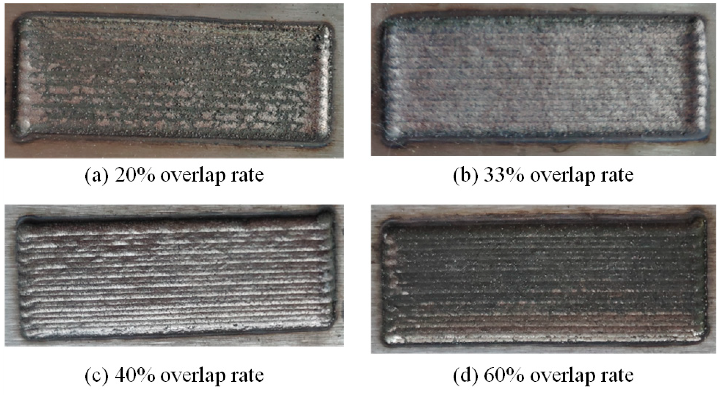
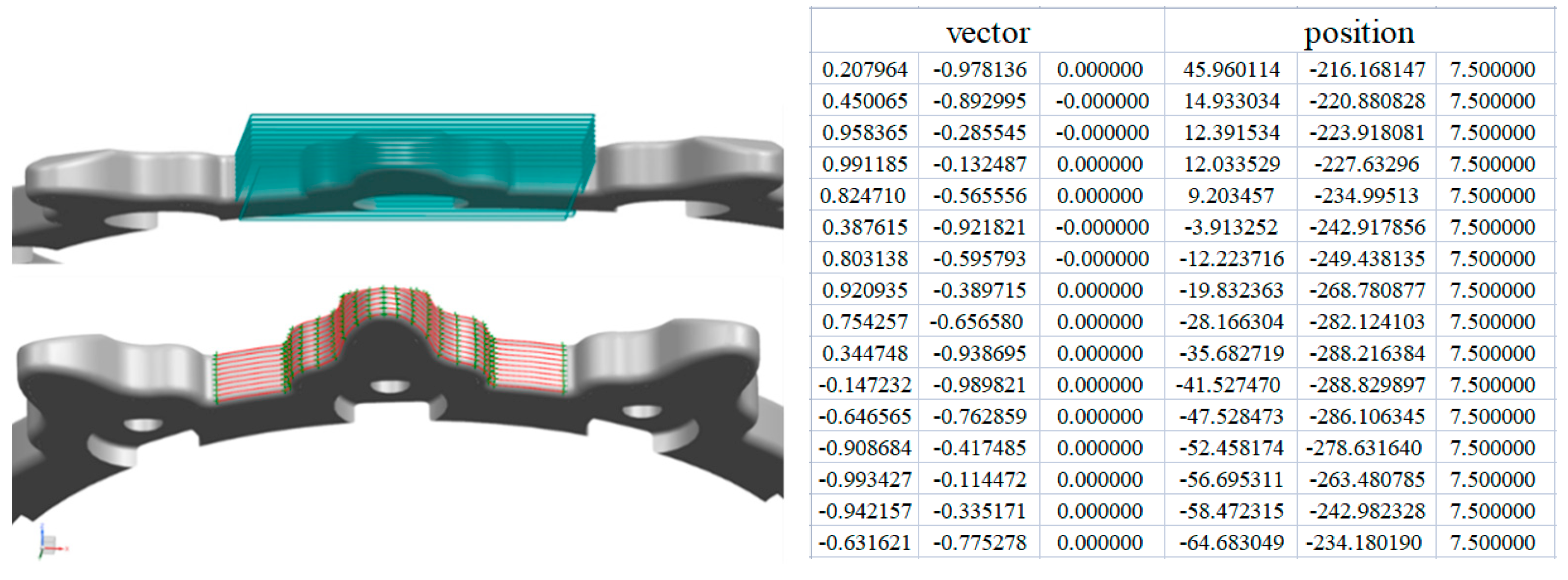
  • Based on the principle of mass conservation, we analyzed surface curvature characteristics and developed a multi-track cladding model to determine the optimal overlap rate between adjacent cladding tracks. The model demonstrated a good fit with an R2 value of 0.92. Path point positions were determined using a slicing method and final processing point pose data were calculated using vector formulas.
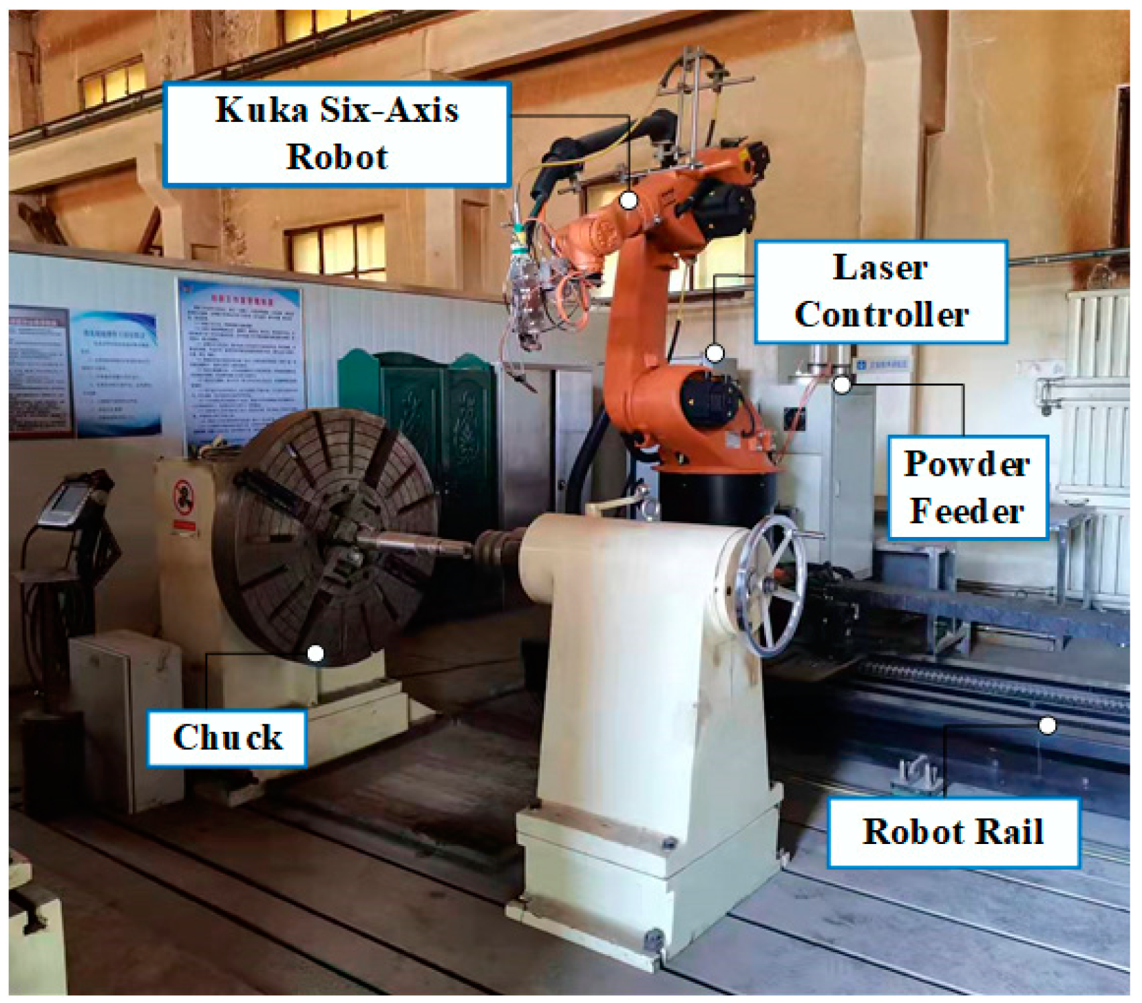
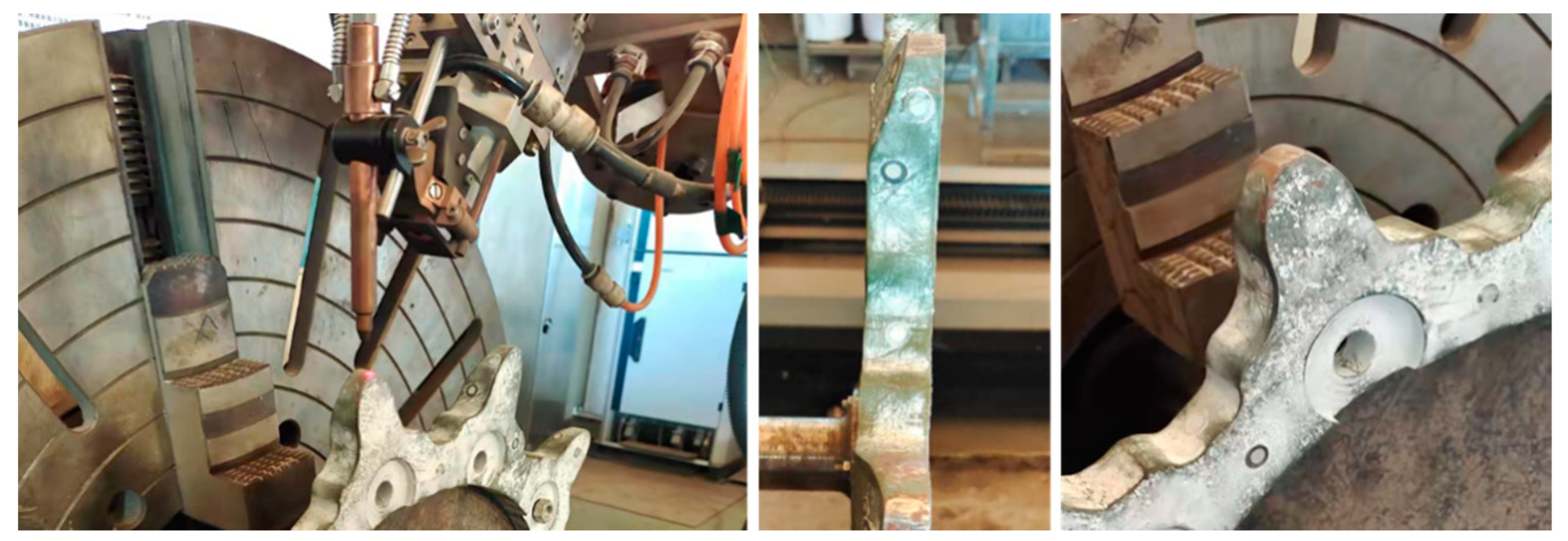
  • The algorithm was applied to a critical metal component—a single gear tooth–using a 38% overlap rate. Simulation results validated the accuracy of the laser scanning path. The cladding material, Ni60 alloy powder, resulted in a smooth, defect-free surface, with a reduced post-processing time and improved material efficiency.

Author Contributions

Conceptualization, J.L. and Z.B.; methodology, J.L.; validation, D.S.; writing—original draft, J.L.; writing—review and editing, Z.B.; visualization, D.S. All authors have read and agreed to the published version of the manuscript.

Funding

This research was supported by the Scientific Research Start-up Fund of Anhui Polytechnic University (No. 2022YQQ032 and No. 2022YQQ036), Research Start-up Fund for Introduced Talent (No. wzyrc202404), the Open Research Fund of Jiangsu Key Laboratory of Digital Manufacturing for Industrial Equipment and Control Technology (No. DM202206), the Natural Science Research Project of Anhui Educational Committee (No.2023AH050939), the Key Research and Development Plan of Anhui Province (No. 2022a05020006) and the Major science research project of Anhui Province Colleges and Universities (No. 2022AH040134). Wuhu science and technology project (No. 2022jc23).

Data Availability Statement

The original contributions presented in the study are included in the article, further inquiries can be directed to the corresponding author.

Conflicts of Interest

The authors declare that they have no known competing financial interests or personal relationships that could have appeared to influence the work reported in this paper.

References

  1. Liu, Y.; Xu, T.; Li, G.; Li, Z.; Du, F.; Chen, G. A multi-objective optimization of laser cladding process of Ni-based coating on the preheated copper alloy. Mater. Today Commun. 2023, 35, 105614. [Google Scholar] [CrossRef]
  2. Qie, J.; Miao, Y.; Liu, H.; Han, T.; Shao, Z.; Duan, J. Design and Process Planning of Non-Structured Surface Spray Equipment for Ultra-Large Spaces in Ship Section Manufacturing. J. Mar. Sci. Eng. 2023, 11, 1723. [Google Scholar] [CrossRef]
  3. Zhu, R.; Gao, W. Wear-resistance Performance of Spray-welding Coating by Plasma Weld-surfacing. J. Wuhan Univtechnol. 2018, 33, 414–418. [Google Scholar] [CrossRef]
  4. Calleja, A.; Bo, P.; González, H.; Bartoň, M.; López de Lacalle, L.N. Highly accurate 5-axis flank CNC machining with conical tools. Int. J. Adv. Manuf. Technol. 2018, 97, 1605–1615. [Google Scholar] [CrossRef]
  5. Kalami, H.; Urbanic, J. Process planning solution strategies for fabrication of thin-wall domes using directed energy deposition. Int. J. Comput. Integr. Manuf. 2021, 35, 493–509. [Google Scholar] [CrossRef]
  6. Chang, Y.Y.; Qiu, J.R.; Chen, Y.X.; Hwang, S.J. Research on deposition toolpath planning and laser head Z-axis rising height setting for directed energy deposition. Opt. Laser Technol. 2023, 161, 109198. [Google Scholar] [CrossRef]
  7. Feng, H.; Li, J.F.; Sun, J. Study on Remanufacturing Repair of Damage Crank Shaft Journal Surface by Laser Cladding. Chin. J. Lasers 2014, 41, 80–85. [Google Scholar]
  8. Li, W.; Yao, Y.; Wu, H.; Deng, S.; Liao, H.; Costil, S. Development of robotized spraying trajectory of multi-featured parts in cold spray additive manufacturing system. DVS-Berichte 2022, 4, 160–163. [Google Scholar]
  9. Wu, H.; Liu, S.; Lewke, M.; Li, W.; Raoelison, R.N.; List, A.; Gärtner, F.; Liao, H.; Klassen, T.; Deng, S. Strategies and analyses for robot trajectory optimization in thermal and kinetic spraying. DVS-Berichte 2022, 5, 299–305. [Google Scholar]
  10. Jin, Y.; Du, J.; He, Y.; Fu, G. Modeling and process planning for curved layer fused deposition. J. Adv. Manuf. Tech. 2017, 91, 273–285. [Google Scholar] [CrossRef]
  11. Huang, Y.; Sun, W.L.; Chen, Y.; Huang, H.B.; Liu, J.D. Rapid Processing Path Generation Method for Curved Surface Plastic Mold Remanufacturing by Laser Cladding. China Surf. Eng. 2017, 30, 150–158. [Google Scholar]
  12. Su, H.; Shi, T.; Shi, S.H.; Fu, G. Algorithm and Implementation of Laser Cladding with Equal Overlapping Ratio on Free-Form Surface. China J. Lasers 2020, 47, 0402008. [Google Scholar] [CrossRef]
  13. Guo, M.; Gao, Q. Application of Laser Cladding Technology in Repairing Automobile Stamping Die. Die Mould. Manuf. 2023, 23, 52–56. [Google Scholar]
  14. Zheng, Z. Research on Laser Selective Melting Process of Tantalum Metal Powder Based on Wire Gas Explosion Method. Master’s Thesis, Foshan University, Foshan, China, 2021. [Google Scholar] [CrossRef]
  15. Xia, L. Research on Additive Manufacturing Software Platform and Slicing Algorithms. Master’s Thesis, Chongqing Uviversity of Technology, Chongqing, China, 2024. [Google Scholar] [CrossRef]
  16. Wang, R.; Xiong, Y.; Yang, K.; Zhang, T.; Zhang, F.; Xiong, B.; Hao, Y.; Zhang, H.; Chen, Y.; Tang, J. Advanced progress on the significant influences of multi-dimensional nanofillers on the tribological performance of coatings. RSC Adv. 2023, 13, 19981–20022. [Google Scholar] [CrossRef] [PubMed]
  17. Zhang, T.; Xiao, N.; Yang, K.; Zhang, F.; Hao, Y.; Zhang, C.; Yin, X.; Zhu, Y. Analysis of tribological behaviors and regulating functions at elevated temperatures of microchannel interfaces prepared in Ti-base alloys. RSC Adv. 2023, 13, 15674–15688. [Google Scholar] [CrossRef]
  18. Wang, T.; Yang, L.I.; Wang, N.; Zhang, L.F.; Tang, J. Effects of Machining Track of Laser Cladding TC4 Titanium Alloy on Surface Morphology. Hot Work Technol. 2019, 48, 138–141. [Google Scholar]
  19. Rashid, R.R.; Barr, C.J.; Palanisamy, S.; Nazari, K.A.; Orchowski, N.; Matthews, N.; Dargusch, M.S. Effect of clad orientation on the mechanical properties of laser-clad repaired ultra-high strength 300M steel. Surf. Coat Technol. 2019, 380, 125090. [Google Scholar] [CrossRef]
  20. Carrullo, J.C.; Falcón, J.C.; Borrás, V.A. Influence of process parameters and initial microstructure on the oxidation resistance of Ti48Al2Cr2Nb coating obtained by laser metal deposition. Surf. Coat. Technol. 2019, 25, 114–124. [Google Scholar] [CrossRef]
  21. Morake, J.B.; Mutua, J.M.; Ruthandi, M.M.; Olakanmi, E.O. The potential use of laser cladded functionally graded materials to mitigate degradation in boiler tube heat exchangers for power plant applications: A review. Surf. Eng. 2023, 39, 677–721. [Google Scholar] [CrossRef]
  22. Zheng, Q.; Chen, T.; Li, H. Enhanced mechanical properties of molybdenum-coated aluminium via laser cladding. Surf. Eng. 2023, 39, 56–64. [Google Scholar] [CrossRef]
  23. Jian, Y.; Xu, P.; Zheng, Y. In-situ laser cladding preparation and biocompatibility of TiNbTa biological coating. J. Mech. Sci. Technol. 2024, 6, 1–10. [Google Scholar] [CrossRef]
  24. Wang, R.; Ouyang, C.; Li, Y.; Zhao, C.; Bai, Q. Microstructure and tribological properties of Stellite 12 coating by laser cladding on 304 stainless steel surface. J. Mech. Sci. Technol. 2023, 37, 3953–3960. [Google Scholar] [CrossRef]
  25. Su, X.; Gao, Y.; Yin, F.; Li, S. Investigation on the Influence of Different Coating Surfaces on the Adhesive Force of Hydrate Particles. J. Mar. Sci. Eng. 2024, 12, 232. [Google Scholar] [CrossRef]
  26. Sun, W.; Zhang, D.; Chen, X.; Wang, K.; Zhang, J.; Jia, Y. Effect of the scanning speed of laser cladding on microstructure and mechanical properties of WC/Ni composite coatings. J. Mar. Sci. Eng. 2022, 36, 679–687. [Google Scholar] [CrossRef]
  27. Karşi, A.; Altay, M.; Aydin, H.; Bayram, A. Optimization of Laser Cladding Process Parameters of a Martensitic Stainless Steel Coating on GGG70L Ductile Cast Iron. Laser Eng. 2023, 54, 19. [Google Scholar]
  28. Han, T.; Xiao, M.; Zhang, J.; Feng, X.; Shen, Y. Laser cladding composite coating on mild steel using Ni–Cr–Ti–B4C powder. Surf. Eng. 2018, 36, 1278–1284. [Google Scholar] [CrossRef]
  29. Li, M.; Huang, K.; Yi, X. Crack formation mechanisms and control methods of laser cladding coatings: A review. Coatings 2023, 13, 1117. [Google Scholar] [CrossRef]
  30. Liang, Y.; Liao, Z.Y.; Zhang, L.L.; Cai, M.W.; Wei, X.S.; Shen, J. A review on coatings deposited by extreme high-speed laser cladding: Processes, materials, and properties. Opt. Laser Technol. 2023, 164, 109472. [Google Scholar] [CrossRef]
  31. Ding, H.; Yang, T.; Wang, W.; Zhu, Y.; Lin, Q.; Guo, J.; Xiao, Q.; Gan, L.; Liu, Q. Optimization and wear behaviors of 316L stainless steel laser cladding on rail material. Wear 2023, 523, 204830. [Google Scholar] [CrossRef]
  32. Wei, R.; Mao, M.; Liang, J.; Zhao, C.; Ouyang, C.; Wang, R.; Bai, Q.; Deng, R.; Li, H.; Bian, Q. Study of the effect of overlap rate on the failure form, microstructure and wear resistance of multilayer laser cladding on grey cast iron surfaces. Tribol. Int. 2024, 194, 109568. [Google Scholar] [CrossRef]
  33. Bu, X.; Xu, X.; Lu, H.; Liang, Y.; Bian, H.; Luo, K.; Lu, J. Effect of overlap rate on the microstructure and properties of Cr-rich stainless steel coatings prepared by extreme high-speed laser cladding. Surf. Coat. Technol. 2024, 487, 131025. [Google Scholar] [CrossRef]
Figure 1. Illustration of laser processing parameters.
Metals 14 01055 g001
Figure 2. Three-dimensional energy distribution diagram of extended top-hat Gaussian light source.
Metals 14 01055 g002
Figure 3. Schematic diagram of the single-track profile fitting equation.
Metals 14 01055 g003
Figure 4. Comparison of coating morphologies and fitting functions.
Metals 14 01055 g004
Figure 5. Coating morphology at different overlap ratios: (a) high overlap, (b) low overlap, and (c) ideal overlap.
Metals 14 01055 g005
Figure 6. Illustration of an ideal overlap distance.
Metals 14 01055 g006
Figure 7. Schematic of a multi-track overlay on a curved surface.
Metals 14 01055 g007
Figure 8. Schematic of a laser head pose.
Metals 14 01055 g008
Figure 9. The cladding surface with four different overlap rates.
Metals 14 01055 g009
Figure 10. Schematic of the laser cladding system.
Metals 14 01055 g010
Figure 11. Pre-coating part morphology.
Metals 14 01055 g011
Figure 12. Three-dimensional part model.
Metals 14 01055 g012
Figure 13. Laser scanning path data.
Metals 14 01055 g013
Figure 14. Robotic path simulation.
Metals 14 01055 g014
Figure 15. Comparison of gear post-coating morphology.
Metals 14 01055 g015
Table 1. Single-track overlay cross-section shape parameters under different process parameters.
Laser Power (W)Scanning Speed (mm/s)Width (mm)Height (mm)Radius (mm)Aspect Ratio
y180042.170.881.110.405
y2100062.390.641.440.268
y3120062.991.21.530.401
y4100042.250.611.340.271
Table 2. Comparison of theoretical and actual overlap.
Laser Power
(KW)
Scanning Speed
(mm/s)
Theoretical Overlap Rate %Actual Overlap Rate %Error
%
1.064040.932.33
1.084242.22.07
1.264241.171.95
1.284141.862.09
Table 3. Chemical composition of Ni60.
ElementCCrSiBFeNi
(wt.%)0.5–114–193.5–53.0–4.5≤8Bal.
Table 4. Laser process parameters.
Laser Power
/W
Defocus Amount
/mm
Powder Feeding Rate/(g/min)Carrier Gas Flow Rate
/L/h
Scanning Speed
/(mm/s)
Overlap
18001615600838%
Disclaimer/Publisher’s Note: The statements, opinions and data contained in all publications are solely those of the individual author(s) and contributor(s) and not of MDPI and/or the editor(s). MDPI and/or the editor(s) disclaim responsibility for any injury to people or property resulting from any ideas, methods, instructions or products referred to in the content.

