Article

Effects of the Primary Carbide Distribution on the Evolution of the Grain Boundary Character Distribution in a Nickel-Based Alloy

1
School of Materials Science and Engineering, Shanghai University, Shanghai 200444, China
2
State Key Laboratory of Advanced Special Steel, Shanghai University, Shanghai 200444, China
*
Authors to whom correspondence should be addressed.
Metals 2024, 14(9), 960; https://doi.org/10.3390/met14090960 (registering DOI)
Submission received: 4 July 2024 / Revised: 19 August 2024 / Accepted: 22 August 2024 / Published: 25 August 2024

Abstract

:
Grain boundary engineering (GBE) was carried out on a nickel-based alloy (GH3535, Ni-16Mo-7Cr-4Fe), which intrinsically has many strings of primary molybdenum carbides. The strings induce inhomogeneous grain size distributions and increase the difficulties in achieving a GBE microstructure. In this work, the effects of the primary carbide distribution on the grain boundary network (GBN) evolution were investigated. A higher proportion of Σ3n grain boundaries (GBs) associated with extensive multiple twinning events was achieved in the specimen with more dispersive and finer primary carbides, which are the results of cross-rolling, i.e., cold rolling with a changed direction. In a starting microstructure with many strings of primary carbides, the dense and frequent occurrence of particle-stimulated nucleation (PSN) around the carbides induced more general high-angle GBs into the GBN, and the inhibition of GB migrations by the carbide strings suppressed the formation of large-sized highly twinned grain clusters. As a consequence, the Σ3n GBs could not be effectively enhanced.

1. Introduction

The molten salt reactor (MSR) is one of the six fourth-generation reactor designs [1]. The main structural material used in an MSR is exposed to an environment of high-temperature molten salts and fission products. In the 1960s, Hastelloy N, a nickel-based solution-strengthened alloy, was invented at Oak Ridge National Laboratory (ORNL) for an experimental MSR [2]. However, the MSR constructed at ORNL was shut down for political reasons after 4 years’ operation. The grain boundary (GB) embrittlement caused by the fission product tellurium (Te) was found [3]. The depth of cracking observed in the MSR would not be acceptable for a 30-year design life of a commercial reactor [2]. Therefore, it is important to inhibit the intergranular embrittlement resulting from Te.
Grain boundary engineering (GBE) was reported to be capable of reducing intergranular corrosion [4], intergranular stress corrosion cracking [5] and fatigue fracture [6] in some face-centered cubic (FCC) materials with low stacking fault energy (SFE), such as austenitic stainless steels [7,8,9], Ni-based alloys [10,11,12,13], copper and its alloys [14]. The proportion of low-Σ (Σ ≤ 29) coincidence site lattice (CSL) GBs can be greatly enhanced through GBE [15,16]. Most of them are of the Σ3n (n = 1, 2, 3…) type and are encircled by random high-angle GBs, the inside of which can be recognized as a highly twinned grain cluster [17]. The highly twinned grain clusters were also termed twin-related domains (TRDs) by Reed et al. [18].
The nickel-based GH3535 alloy is a structural material for the Chinese experimental MSR. The GH3535 alloy is an alloy containing a large amount of molybdenum, resulting in plenty of large-sized primary carbides. Generally, primary carbides are formed during solidification and cannot be substantially eliminated during solution heat treatment, which is largely different from the much smaller-sized secondary carbides, which are precipitated from the solid matrix of alloys and would dissolve upon solution heat treatment. The large-sized primary carbides would induce high stored energy in the matrix around these carbides after deformation and hence result in particle-stimulated nucleation (PSN) and smaller grain sizes upon annealing [19]. Furthermore, carbides would also significantly drag boundaries from movement [20]. As a result, the primary carbides would play an important role in the evolution of the grain boundary character distribution (GBCD) during GBE. The effects of the initial grain size [21], the annealing time and temperature [9,22], the number of processing iterations [23,24] and the amount of pre-deformation [22,25] on the evolution of the GBCD during GBE were studied extensively. In addition, the effects of GBE on the morphology, size and type of secondary carbides have also been reported [26,27,28]. Our previous work [12] found that smaller-sized grain clusters formed around the pre-existing secondary carbides at the GBs and hence yielded a lower proportion of low-ΣCSL GBs. However, primary carbides of GH3535 alloy can hardly be eliminated during solution heat treatment. Therefore, this work aims to investigate the effect of the primary carbide distribution on the evolution of the GBCD in GH3535 alloy.
In this paper, the distribution of primary carbides was adjusted by means of altering the cold-rolling direction and heat treatments in the starting specimens. After that, three types of specimens with different primary carbide distributions were obtained, and then the thermal-mechanical processing (TMP) of GBE was carried out on the three specimens to reveal the effects of different initial primary carbide distributions on the evolution of the GBCD.

2. Experimental Details

The composition of the GH3535 alloy used in this investigation is shown in Table 1. The as-received hot-rolled plate specimen with a thickness of 10 mm was cold-rolled to a thickness of 6 mm, and then was solution annealed at 1177 °C for 30 min for the starting material. The starting material was cold-rolled with the reduction of 50% along the previous rolling direction to a thickness of 3 mm. The 50% cold reduction ratio was achieved through about 8~10 passes for different individual sample plates, and the reduction in each pass is not exactly the same. Then, the specimens were subsequently solution-annealed under two conditions: 1100 °C × 30 min and 1177 °C × 30 min, and they were designated as specimens S0 and L0, which had small and large grain sizes, respectively. For the last group specimen, in order to eliminate the string-like distribution of primary carbides and obtain a more dispersive distribution of primary carbide particles, small plates were cut from the starting material for cross-rolling. The cross-rolling was carried out perpendicular to the previous rolling direction of the starting material, with a reduction of 50% also. A similar number of passes of rolling of the sample with the changed rolling direction was controlled. The obtained 3.0 mm thick specimen was subsequently solution-annealed at 1100 °C for 30 min, and followed by cold rolling along the last direction once again to the thickness of 1.5 mm, and then annealed at 1100 °C for 30 min. The cold rolling was carried out on a Y132S-4 twin-roller mill (Shanghai Institute of Technology, Shanghai, China) with a roller diameter of 130 mm. The last group specimen with the changed rolling direction was designated as specimen SC0 (S stands for a smaller grain size as compared with that of specimen L0 and C stands for cross-rolling).
Specimens S0, L0 and SC0 were all subjected to tensile deformation of 3%, 5% and 7%, respectively. Then, these nine tensile-deformed specimens were annealed at 1177 °C for 20 min and subsequently water-quenched. Thereafter, these specimens were designated as S3, S5, S7, L3, L5, L7 and SC3, SC5, SC7. The TMP procedures of all the specimens are shown in Table 2.
The cross-section of the specimens was grounded using SiC sand papers in the order of 400, 600, 800, 1000, 1500 and 2000 grits and then mechanically polished. The polished specimens were then electro-polished in a solution of 20% HCLO4 + 80% CH3COOH with 30 V direct current for 120 s. A solution of 10% oxalic acid + 90% H2O was used for the electro-etching with 20 V direct current for 90 s. After that, the specimens were examined with a KEYENCEVH-Z100 optical microscopy (OM) (KEYENCE, Osaka, Japan) and CamScan Apollo 300 thermal field emission gun scanning electron microscopy (SEM) (Obducat CamScan, Cambridge, UK) attached with an HKL-Channel 5 EBSD system (Oxford Instruments, High Wycombe, UK) and an energy dispersive spectrometer (EDS) (Oxford Instruments, High Wycombe, UK). The operation conditions of EBSD were as follows: 20 kV accelerating voltage, 30 mm working distance, 70° beam incidence angle. Areas of 1200 μm × 800 μm were mapped with a step size of 4 μm for EBSD. To reduce the experiment error, at least three areas were scanned with EBSD in each specimen, and the mean results are reported. The software HKL-Channel5 (Oxford Instruments, High Wycombe, UK) was used to analyze the EBSD data. The proportion of GBs defined by the CSL model was expressed as a length fraction by dividing the number of datapoints of a particular boundary type with that of the entire GBs. The Palumbo–Aust criterion [29] was used to define the CSL misorientations. The line intercept method was used to measure the mean grain size of the specimens. The size distribution of primary carbides was obtained with the image processing software Image J (1.52k, National Institutes of Health, Bethesda, MD, USA).

3. Results and Discussion

Through the TMPs, as described in the previous section, three types of primary carbide distributions in the specimens were obtained and designated as the specimen S, L and SC groups. The optical micrographs, grain boundary maps and grain orientation maps of the three specimens (S0, L0 and SC0) are displayed in Figure 1. Many dark primary carbide particles can be observed in the optical micrographs of Figure 1a–c, as indicated by the red cycles in Figure 1a as an example. The carbides were analyzed with EDS, as shown in Figure 2, which indicates that these carbides are M6C-type (M is mainly molybdenum) carbides according to [30], although the shape and size of the primary carbides are different from one specimen to another. Pores can be seen near some of the primary carbides in the SEM image of Figure 2b, which were the consequences of the electro-etching.
Many strings of primary carbides along the previous rolling direction (vertical direction in the figure) were found in specimen S0, while the strings are much fewer in specimen SC0, as shown in Figure 1. Another feature of specimen S0 as compared with the other specimens is that large grains and small grains distribute alternately perpendicular to the previous rolling direction, as shown in Figure 1a. The grains are smaller in the areas of densely distributed primary carbides owing to the more concentrated strain near the primary carbides during the deformation of the specimen. The enforced strain gradient in the vicinity of the particles creates a region with a large orientation gradient (particle deformation zone or PDZ), which is an ideal site for the development of a recrystallization nucleus upon annealing [31,32]. The mean grain size of specimen L0 is 19.0 µm, which is larger than that of specimen S0 due to the higher annealing temperature (1177 °C). For specimen SC0 with the changed cold-rolling direction, the distribution of primary carbides is the most dispersive, indicating that the cross-rolling has a significant effect on the fragmentation of the string distribution of carbides. Moreover, the mean grain size of specimen SC0 is 12.9 µm, which is smaller than that of specimen S0 (14.2 µm). The proportions of low-ΣCSL GBs, as obtained with EBSD measurement of specimens S0, L0 and SC0, are 41.7%, 50.7% and 31.9%, respectively, while the grain orientation maps and the inserted pole figures indicate no obvious texture in the three specimens.
Figure 3 shows the grain size distributions of specimens S0, L0 and SC0. Specimen S0 has two peaks, while there is only one peak in specimens L0 and SC0, respectively. The feature of large grains and small grains distributing alternately perpendicular to the previous rolling direction in specimen S0 contributes to the two peaks of the grain size distribution. One peak is at about 10 μm of the grain size and the other is at about 40 μm of that. For specimen L0, the average grain size is larger because of the higher solution-annealing temperature (1177 °C), contributing to one peak at about 30 μm of the grain size. The distribution of the primary carbides in specimen SC0 is the most homogenous one, which is the result of the changed cold-rolling direction. Therefore, there is only one peak at about 10 μm of the grain size distribution.
The three types of specimens S0, L0 and SC0 were subjected to tensile deformation of 3%, 5% and 7%, respectively. After that, strain tends to concentrate near the primary carbides, as revealed by the local misorientation map of the deformed specimen S5 (5% tensile strain), with an example shown in Figure 4. The slightly deformed specimens were subsequent annealed at 1177 °C for 20 min as the GBE-type TMPs, as shown in Table 2, and the optical microstructures of all nine GBE specimens are shown in Figure 5. In order to distinguish the difference in the primary carbide size of the three group GBE specimens, the size distributions of primary carbides as measured on the SEM images were analyzed and the results are shown in Figure 6. The strings are composed of multiple particles that are so close to each other they cannot be divided when determining the size of the primary carbides. Most strings are longer than 8 μm and these strings are the aggregates of at least two individual particles. If the length is shorter than 8 μm, it is highly probable it is an isolated primary carbide particle. Therefore, both the lengths of primary carbide particles and primary carbide strings were analyzed when studying the size distribution of primary carbides. In general, the size of primary carbide strings was between 8 μm and 20 μm. The proportions of small primary carbides in the specimens decrease in the sequence of SC5, L5 and S5, the order of which is the same as before the TMP of GBE. This indicates that the cross-rolling has significant effect on the fragmentation of the carbide strings.
The grain boundary maps of all nine GBE specimens are shown in Figure 7. The maps show that the different initial primary carbide distributions resulted in obvious differences in the grain boundary network (GBN) in the specimens. Two highly twinned grain clusters are highlighted by the gray background in Figure 7e,g as examples. The formation of this kind of grain cluster through multiple twinning starting from a single nucleus during recrystallization is one of the pronounced features of the GBE microstructure [17]. All the grain boundaries inside this kind of cluster are of the Σ3n-type (n = 1, 2, 3…), while the outer boundaries are generally random GBs. The grain size and grain cluster size, together with the proportions of low-ΣCSL GBs, are used to describe the GBN. The mean sizes of both the grains and grain clusters of the GBE specimens are, respectively, larger than those of the initial specimens S0, L0 and SC0, as shown in Figure 8. For the S and L group GBE specimens, under the condition of the same pre-strain, the mean grain size of the L group GBE specimens is always larger than that of the S group GBE specimens, which means that the mean grain size increases with the increasing original grain size if other processing conditions are the same. On the one hand, it is well known that GBs are preferential nucleation sites for recrystallization [33]; therefore, a large grain-sized specimen has fewer nucleation sites and the newly formed grains have larger space for growth during recrystallization. On the other hand, a large initial grain size is harmful to the frequent occurrence of multiple twinning events because of the lower changing frequency of migrating GB misorientations. These two reasons contribute to the larger grain size in the L group GBE specimens. Furthermore, the mean grain size of the GBE specimens decreased with the increasing strain from 3% to 7% for the S, L and SC groups. This is because a higher strain will induce a higher nucleation density and hence finer final grain cluster sizes [34].
The low-ΣCSL GB proportions of all the specimens are shown in Figure 9. As shown in Figure 8 and Figure 9, a larger grain cluster size usually, but not necessarily, indicates a higher proportion of low-ΣCSL GBs, such as specimens S3 and SC5. The grain cluster size of specimen S3 is slightly larger than that of specimen SC5, while the overall low-ΣCSL GB proportion of the former is lower, as shown in Figure 9. Our previous study [11] showed that both the grain cluster size and twin grain size are crucial when determining the overall low-ΣCSL GB proportion of a specimen after GBE. Liu [11] proposed that the square of the ratio of the average grain cluster size (D) over the average grain size (d) governed the overall low-ΣCSL GB proportion. The values of (D/d)2 quantify the number of annealing twin grains inside a single grain cluster, and the results are shown in Figure 9. The low-ΣCSL GB proportion has a positive correlation with the value of (D/d)2. The larger value of (D/d)2 indicates a higher proportion of low-ΣCSL GBs.
According to the changes in the low-ΣCSL GB proportions shown in Figure 9, the low-ΣCSL GB proportions obviously increased after GBE and all the three group specimens gained their maximum overall low-ΣCSL GB proportions at the pre-strain of 3%. The low-ΣCSL GB proportions of the three group GBE specimens decreased with the increasing pre-strain. This is owing to the fact that a higher stored energy would induce a higher recrystallization nucleation density and hence a lesser extent of multiple twinning [35].
Furthermore, with a same pre-strain, the low-ΣCSL GB proportions in the SC group specimens are always the highest and those of S group specimens are the lowest. On the one hand, nucleation events prefer to occur in the area around the primary carbides following the recrystallization mechanism of particle-stimulated nucleation (PSN) [36,37]. The size distributions of the primary carbides in GBE specimens S5, L5 and SC5 shown in Figure 6 indicate that specimen S5 has more coarse primary carbide strings where higher stored energy was accumulated during deformation. During subsequent annealing, more nucleation events would occur in the areas with intensive particles owing to the PSN, causing the aggregation of small grain clusters. The majority of the new GBs formed following the PSN mechanism are random GBs [36]. On the other hand, the closely spaced primary carbides would prevent or delay GB migration during recrystallization [12], reducing the occurrence of multiple twinning events. As a result, the size of the grain clusters is smaller near the primary carbides, while large grain clusters would form at a distance away from the primary carbides. Therefore, the S group specimens had a higher nucleation density during recrystallization and hence obtained comparatively smaller grain cluster sizes as well as a lower proportion of low-ΣCSL GBs. The PSN and pinning effect from the primary carbides are hence detrimental to the formation of large grain clusters and a high proportion of low-ΣCSL GBs.
When recrystallization was finished in the specimens, the primary carbides would still drag the grain boundaries from movement during grain growth. Figure 10 shows the SEM images, GBNs and local misorientation maps of the shortly annealed specimen S5-40s and the fully annealed specimen S5. Specimen S5-40s was obtained by subjecting specimen S0 to 5% tensile deformation and subsequent annealing at 1177 °C for 40. In specimen S5-40s, where the recrystallization had just finished, small-sized grains and intensive random boundaries near the primary carbides can be observed in Figure 10a,c, as indicated by the black rectangles. In contrast, by observing the area in the black rectangle in Figure 10b,d, one can see that the grain size near the primary carbides of specimen S5 was almost the same as that of specimen S5-40s, while the grains in areas other than the position of primary carbides underwent extensive growth during the annealing after recrystallization. This indicates that the densely distributed primary carbide strings delayed or prevented the local grain growth after recrystallization.
As a result, the PSN events and the delay of GB migration are more obvious at the positions where the primary carbides are clustering and aggregating as strings. The large and intensive primary carbide strings have a detrimental effect on the enhancement of the low-ΣCSL GB proportion. Therefore, the SC group specimens, whose cold-rolling direction were changed, had the most dispersive primary carbides among the three groups of specimens and hence had the highest proportion of low-ΣCSL GBs after GBE.

4. Conclusions

(1)
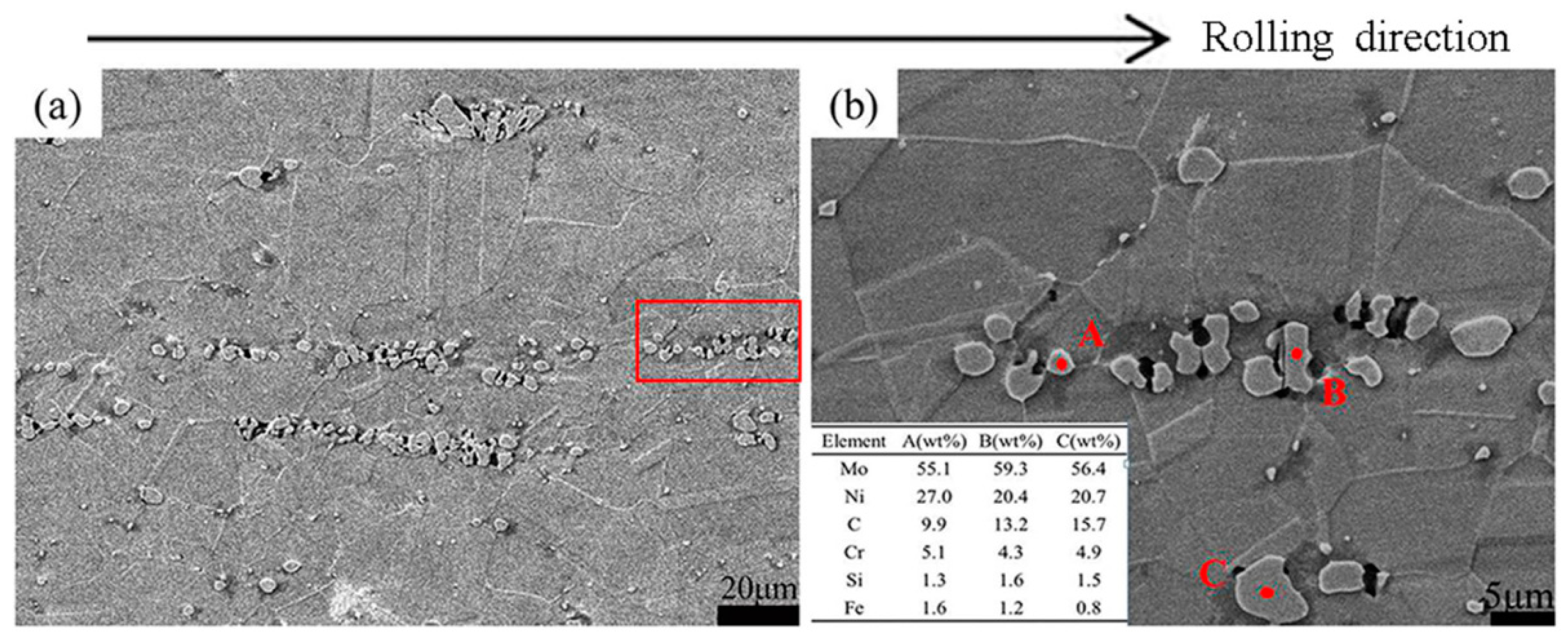
The distribution of primary carbides is intentionally altered by changing the cold-rolling direction in a nickel-based alloy (GH3535, Ni-16Mo-7Cr-4Fe), and its effects on the grain boundary character distribution were investigated in this work.
(2)
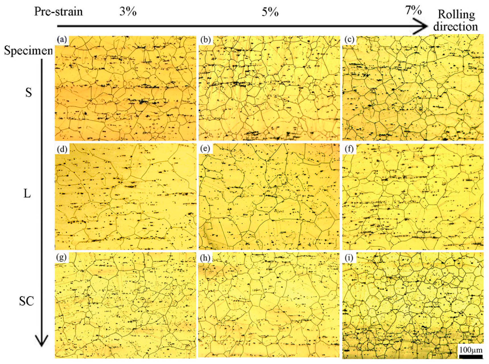
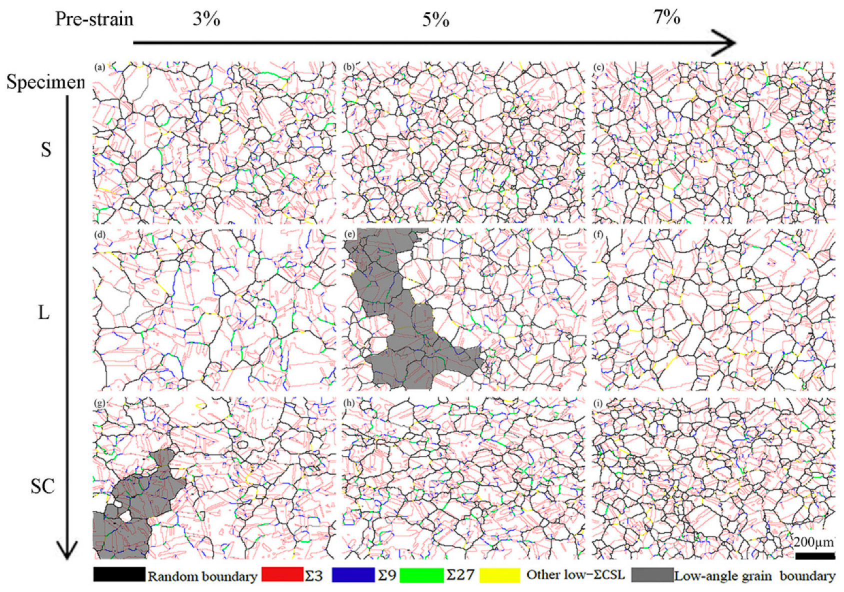
In the sample with many string-like primary carbides along the rolling direction, the intensively distributed primary carbide strings not only induced the occurrence of particle-stimulated nucleation of recrystallization, which increased the random boundary density, but also prevented or delayed the migration of GBs due to the pinning effect.
(3)
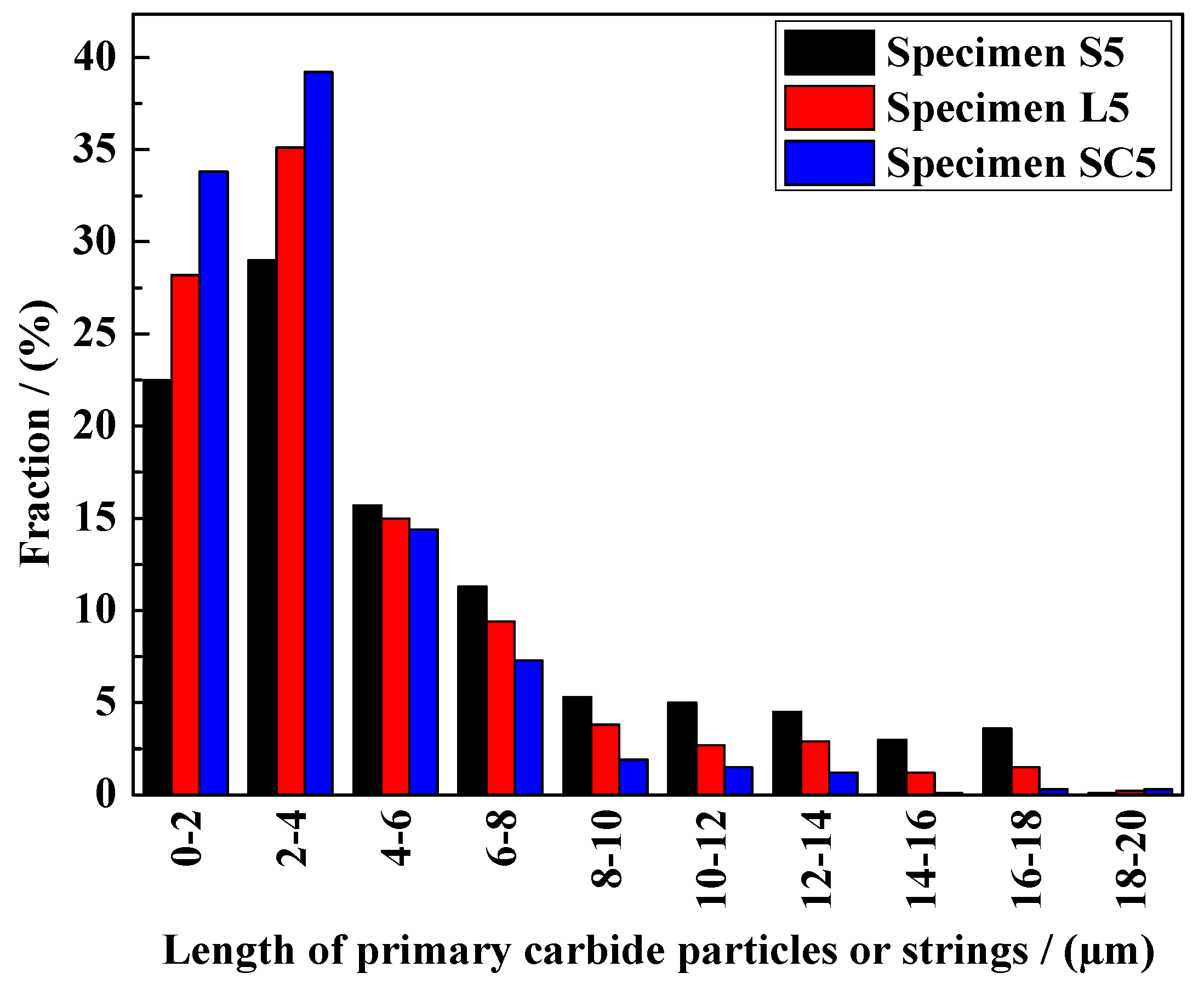
By applying cross-rolling and subsequent annealing, the strings of primary carbides were substantially fragmented, resulting in more dispersive primary carbides. In this case, a higher proportion of Σ3n grain boundaries associated with extensive multiple twinning events can be achieved via routine GBE-type thermal-mechanical processing.

Author Contributions

Conceptualization, S.X. and Q.B.; methodology, S.X. and Y.M.; software, Y.M. and Q.B.; validation, S.X., Y.M. and Q.B.; formal analysis, S.X., Y.M. and Q.B.; investigation, S.X. and Q.B.; resources, Q.B.; data curation, Y.M. and Q.B.; writing—original draft preparation, S.X., Y.M. and Q.B.; writing—review and editing, S.X., Y.M. and Q.B.; visualization, Y.M.; supervision, S.X.; project administration, Q.B.; funding acquisition, S.X. All authors have read and agreed to the published version of the manuscript.

Funding

This research was funded by the National Key Research and Development Program of China grant number 2018YFE0122100 and the National Natural Science Foundation of China grant number 51871144, 51671122.

Data Availability Statement

The data presented in this study are available on request from the corresponding authors.

Acknowledgments

The authors would like to thank Bingyu Liu for her efforts in this work.

Conflicts of Interest

The authors declare no conflict of interest.

References

  1. He, Z.; Gao, L.; Qi, W.; Zhang, C.; Wang, X.; Song, J.; He, X.; Zhang, C.; Tang, H.; Rohan, H.; et al. Molten FLiNaK salt infiltration into degassed nuclear graphite under inert gas pressure. Carbon 2015, 84, 511–518. [Google Scholar] [CrossRef]
  2. Ren, W.; Muralidharan, G.; Wilson, D.F.; Holcomb, D.E. Considerations of alloy N for fluoride salt-cooled high-temperature reactor applications. In Proceedings of the ASME 2011 Pressure Vessels and Piping Conference, Baltimore, MD, USA, 17–21 July 2011; pp. 725–736. [Google Scholar]
  3. Rosenthal, M.; Haubenreich, P.; Briggs, R. The development status of molten-salt breeder reactors. ORNL-4812 1972, 1–30. [Google Scholar] [CrossRef]
  4. Yamada, G.; Kokawa, H.; Yasuda, Y.; Tokita, S.; Yokoyama, T.; Sato, Y.S.; Fujii, H.T.; Tsurekawa, S. Effect of post-GBE strain-sensitisation on corrosion resistance of grain boundary engineered 304 austenitic stainless steel. Philos. Mag. 2013, 93, 1443–1453. [Google Scholar] [CrossRef]
  5. Telang, A.; Gill, A.S.; Tammana, D.; Wen, X.S.; Kumar, M.; Teysseyre, S.; Mannava, S.R.; Qian, D.; Vasudevan, V.K. Surface grain boundary engineering of Alloy 600 for improved resistance to stress corrosion cracking. Mater. Sci. Eng. A 2015, 648, 280–288. [Google Scholar] [CrossRef]
  6. Das, A. Grain boundary engineering: Fatigue fracture. Philos. Mag. 2017, 97, 867–916. [Google Scholar] [CrossRef]
  7. Safari, H.; Rezaeian, A.; Karimzadeh, F. Novel role of thermomechanical grain boundary engineering in the microstructure evolution of austenitic stainless steel. J. Mater. Res. Technol. 2024, 30, 146–163. [Google Scholar] [CrossRef]
  8. Wang, X.; Xue, H.; Zhao, Y.; Zhao, M.; Zhang, T.; Wang, F. Effect of grain boundary engineering on corrosion behavior of 316 L stainless steel bipolar plate in proton exchange membrane fuel cells environment. Mater. Today Commun. 2024, 38, 107773. [Google Scholar] [CrossRef]
  9. Tokita, S.; Kokawa, H.; Sato, Y.S.; Fujii, H.T. In situ EBSD observation of grain boundary character distribution evolution during thermomechanical process used for grain boundary engineering of 304 austenitic stainless steel. Mater. Charact. 2017, 131, 31–38. [Google Scholar] [CrossRef]
  10. Cao, W.; Xia, S.; Bai, Q.; Zhang, W.Z.; Zhou, B.X.; Li, Z.J.; Jiang, L. Effects of initial microstructure on the grain boundary network during grain boundary engineering in Hastelloy N alloy. J. Alloys Compd. 2017, 704, 724–733. [Google Scholar] [CrossRef]
  11. Liu, T.G.; Xia, S.; Li, H.; Zhou, B.X.; Bai, Q.; Su, C.; Cai, Z.G. Effect of initial grain sizes on the grain boundary network during grain boundary engineering in Alloy 690. J. Mater. Res. 2013, 28, 1165–1176. [Google Scholar] [CrossRef]
  12. Liu, T.G.; Xia, S.; Li, H.; Zhou, B.X.; Bai, Q. Effect of the pre-existing carbides on the grain boundary network during grain boundary engineering in a nickel based alloy. Mater. Charact. 2014, 91, 89–100. [Google Scholar] [CrossRef]
  13. Bian, B.; Taheriniya, S.; Muralikrishna, G.M.; Sen, S.; Gammer, C.; Steinbach, I.; Divinski, S.V.; Wilde, G. Coupling of alloy chemistry, diffusion and structure by grain boundary engineering in Ni–Cr–Fe. Acta Mater. 2024, 264, 119602. [Google Scholar] [CrossRef]
  14. Lind, J.; Li, S.F.; Kumar, M. Twin related domains in 3D microstructures of conventionally processed and grain boundary engineered materials. Acta Mater. 2016, 114, 43–53. [Google Scholar] [CrossRef]
  15. Kobayashi, S.; Kobayashi, R.; Watanabe, T. Control of grain boundary connectivity based on fractal analysis for improvement of intergranular corrosion resistance in SUS316L austenitic stainless steel. Acta Mater. 2016, 102, 397–405. [Google Scholar] [CrossRef]
  16. Randle, V. Twinning-related grain boundary engineering. Acta Mater. 2004, 52, 4067–4081. [Google Scholar] [CrossRef]
  17. Bai, Q.; Zhao, Q.; Xia, S.; Wang, B.S.; Zhou, B.X.; Su, C. Evolution of grain boundary character distributions in alloy 825 tubes during high temperature annealing: Is grain boundary engineering achieved through recrystallization or grain growth? Mater. Charact. 2017, 123, 178–188. [Google Scholar] [CrossRef]
  18. David, B.B.; Jonathan, L.; Rupalee, P.M.; Timothy, J.R.; Mukul, K. The formation and characterization of large twin related domains. Acta Mater. 2017, 129, 500–509. [Google Scholar] [CrossRef]
  19. Pereloma, E.V.; Mannan, P.; Gilberto, C.; Saleh, A.A. Particle stimulated nucleation during dynamic and metadynamic recrystallisation of Ni-30%Fe-Nb-C alloy. Mater. Charact. 2017, 125, 94–98. [Google Scholar] [CrossRef]
  20. Katnagallu, S.S.; Mandal, S.; Cheekur Nagaraja, A.; de Boer, B.; Sarma, V.S. Role of carbide precipitates and process parameters on achieving grain boundary engineered microstructure in a Ni-based superalloy. Metall. Mater. Trans. A 2015, 46, 4740–4754. [Google Scholar] [CrossRef]
  21. Feng, W.; Yang, S.; Yan, Y.B. Dependence of grain boundary character distribution on the initial grain size of 304 austenitic stainless steel. Philos. Mag. 2017, 97, 1057–1070. [Google Scholar] [CrossRef]
  22. Kaithwas, C.K.; Bhuyan, P.; Pradhan, S.K.; Mandal, S. Microstructure evolution during low-strain thermo-mechanical processing and its repercussion on intergranular corrosion in alloy 600H. Mater. Charact. 2018, 145, 582–593. [Google Scholar] [CrossRef]
  23. Mandal, S.; Bhaduri, A.K.; Sarma, V.S. One-step and iterative thermo-mechanical treatments to enhance Σ3n boundaries in a Ti-modified austenitic stainless steel. J. Mater. Sci. 2011, 46, 275–284. [Google Scholar] [CrossRef]
  24. Owen, G.; Randle, V. On the role of iterative processing in grain boundary engineering. Scr. Mater. 2006, 55, 959–962. [Google Scholar] [CrossRef]
  25. Barr, C.M.; Leff, A.C.; Demott, R.W.; Doherty, R.D.; Taheri, M.L. Unraveling the origin of twin related domains and grain boundary evolution during grain boundary engineering. Acta Mater. 2018, 144, 281–291. [Google Scholar] [CrossRef]
  26. Li, H.; Xia, S.; Zhou, B.X.; Chen, W.J.; Hu, C.L. The dependence of carbide morphology on grain boundary character in the highly twinned Alloy 690. J. Nucl. Mater. 2010, 399, 108–113. [Google Scholar] [CrossRef]
  27. Li, H.; Liu, X.R.; Zhang, K.; Liu, W.Q.; Xia, S.; Zhou, B.X. Effects of the triple junction types on the grain boundary carbide precipitation in a nickel-based superalloy, a statistical analysis. Philos. Mag. 2019, 99, 318–327. [Google Scholar] [CrossRef]
  28. Li, H. Twinning structure of M23C6 carbide precipitated at twin related grain boundaries in alloy 600. Philos. Mag. 2016, 96, 551–559. [Google Scholar] [CrossRef]
  29. Palumbo, G.; Aust, K.T.; Lehockey, E.M.; Erb, U.; Lin, P. On a more restrictive geometric criterion for “special” CSL grain boundaries. Scr. Mater. 1998, 38, 1685–1690. [Google Scholar] [CrossRef]
  30. Xu, Z.; Jiang, L.; Dong, J.; Li, Z.; Zhou, X. The effect of silicon on precipitation and decomposition behaviors of M6C carbide in a Ni–Mo–Cr superalloy. J. Alloys Compd. 2015, 620, 197–203. [Google Scholar] [CrossRef]
  31. Schäfer, C.; Song, J.; Gottstein, G. Modeling of texture evolution in the deformation zone of second-phase particles. Acta Mater. 2009, 57, 1026–1034. [Google Scholar] [CrossRef]
  32. Pradhan, S.K.; Bhuyan, P.; Kaithwas, C.; Mandal, S. Strain-annealing based grain boundary engineering to evaluate its sole implication on intergranular corrosion in extra-low carbon type 304L austenitic stainless steel. Metall. Mater. Trans. A 2018, 49, 2817–2831. [Google Scholar] [CrossRef]
  33. Oliferuk, W.; Maj, M. Effect of pre-strain direction on energy storage process during tensile deformation of polycrystal. Mater. Sci. Eng. A 2004, 387, 218–221. [Google Scholar] [CrossRef]
  34. Field, D.P.; Bradford, L.T.; Nowell, M.M.; Lillo, T.M. The role of annealing twins during recrystallization of Cu. Acta Mater. 2007, 55, 4233–4421. [Google Scholar] [CrossRef]
  35. Jin, Y.; Lin, B.; Bernacki, M.; Rohrer, G.S.; Rollett, A.D.; Bozzolo, N. Annealing twin development during recrystallization and grain growth in pure nickel. Mater. Sci. Eng. A 2014, 597, 295–303. [Google Scholar] [CrossRef]
  36. Xu, W.; Ferry, M.; Cairney, J.M.; Humphreys, F.J. Three-dimensional investigation of particle-stimulated nucleation in a nickel alloy. Acta Mater. 2007, 55, 5157–5167. [Google Scholar] [CrossRef]
  37. Huang, Y.; Humphreys, F.J. The effect of solutes on grain boundary mobility during recrystallization and grain growth in some single-phase aluminum alloys. Mater. Chem. Phys. 2012, 132, 166–174. [Google Scholar] [CrossRef]
Figure 1. The optical microstructures, grain boundary maps and grain orientation maps with {111} pole figure inserted, of specimens S0 (a,d,g), L0 (b,e,h), and SC0 (c,f,i).
Metals 14 00960 g001
Figure 2. SEM images and EDS results of the primary carbide particles in the matrix of specimen S0. The higher magnification image of the red rectangle area in (a) is shown in (b).
Metals 14 00960 g002
Figure 3. The grain size distributions of specimens S0, L0 and SC0.
Metals 14 00960 g003
Figure 4. (a) SEM image and (b) local misorientation map of the 5%-deformed specimen S5.
Metals 14 00960 g004
Figure 5. Optical microstructures of the GBE specimen, S group ((ac) correspond to S3, S5 and S7), L group ((df) correspond to L3, L5 and L7) and SC group ((gi) correspond to SC3, SC5 and SC7).
Metals 14 00960 g005
Figure 6. Size distributions of primary carbide particle strings of specimens S5, L5 and SC5.
Metals 14 00960 g006
Figure 7. Grain boundary maps of the specimen S group ((ac) correspond to S3, S5, S7), L group ((df) correspond to L3, L5, L7) and SC group ((gi) correspond to SC3, SC5, SC7).
Metals 14 00960 g007
Figure 8. Mean grain size and grain cluster size of the specimens.
Metals 14 00960 g008
Figure 9. Low-ΣCSL GB proportions (solid lines) and values of (D/d)2 (dashed lines) of the specimens.
Metals 14 00960 g009
Figure 10. SEM images, grain boundary maps and local misorientation maps of specimens S5-40s (a,c,e) and S5 (b,d,f). The black rectangles indicate the same areas in the SEM images and their corresponding grain boundary maps.
Metals 14 00960 g010
Table 1. The chemical composition of the investigated GH3535 alloy sample (wt. %).
NiMoCrFeMnSiC
Bal. 16.607.093.830.520.460.04
Table 2. The thermal-mechanical processing of the S, L and SC group GBE specimens.
Cold Rolling
(%)
Pre-Processing
Annealing
Sample IDStrain
(%)
GBE-Processing
Annealing
Sample ID
---3-S3
501100 × 30 minS05-S5
---7-S7
---3-L3
501177 × 30 minL051177 × 20 minL5
---7-L7
---3-SC3
501100 × 30 minSC05-SC5
(cross-rolling)--7-SC7
Disclaimer/Publisher’s Note: The statements, opinions and data contained in all publications are solely those of the individual author(s) and contributor(s) and not of MDPI and/or the editor(s). MDPI and/or the editor(s) disclaim responsibility for any injury to people or property resulting from any ideas, methods, instructions or products referred to in the content.

