Abstract
The crankshaft is a critical component in large marine ships, often regarded as the “heart” of the vessel due to its role in transmitting power and motion. This article addresses the technological challenges in the forging of marine crank throws, a key segment of the crankshaft. The study employed finite element simulations to evaluate three Near-Net-Shape (NNS) forming methods: One-Step Extrusion (OSE), Upsetting/Backward Extrusion (U/BE), and Grooving–upsetting/Backward Extrusion (G–U/BE). The results show that the G–U/BE method requires the lowest load. The grooving–upsetting step in the G–U/BE process forms a rigid journal end web shape that influences the subsequent backward extrusion, with the relative groove depth (the ratio of groove depth to width) playing a crucial role in the final forging quality. Optimal crank throw formation occurs when the ratio is 1.5; deeper grooves increase the load required, diminishing the effectiveness of the grooving–upsetting step. Scaled-down experiments validate G–U/BE as a practical and feasible method for producing large marine crank throw forgings, ensuring both the desired shape and microstructural properties.
1. Introduction
Marine crankshafts are critical components in ship propulsion systems and are subjected to extreme mechanical stresses and fatigue during operation [1]. The manufacturing process of crankshaft throws, particularly through forging, plays a crucial role in determining the quality and performance of the final product. Simulation and experimental testing have become indispensable tools for optimizing these forging processes, enabling engineers to predict and refine the microstructural and mechanical properties of the finished components.
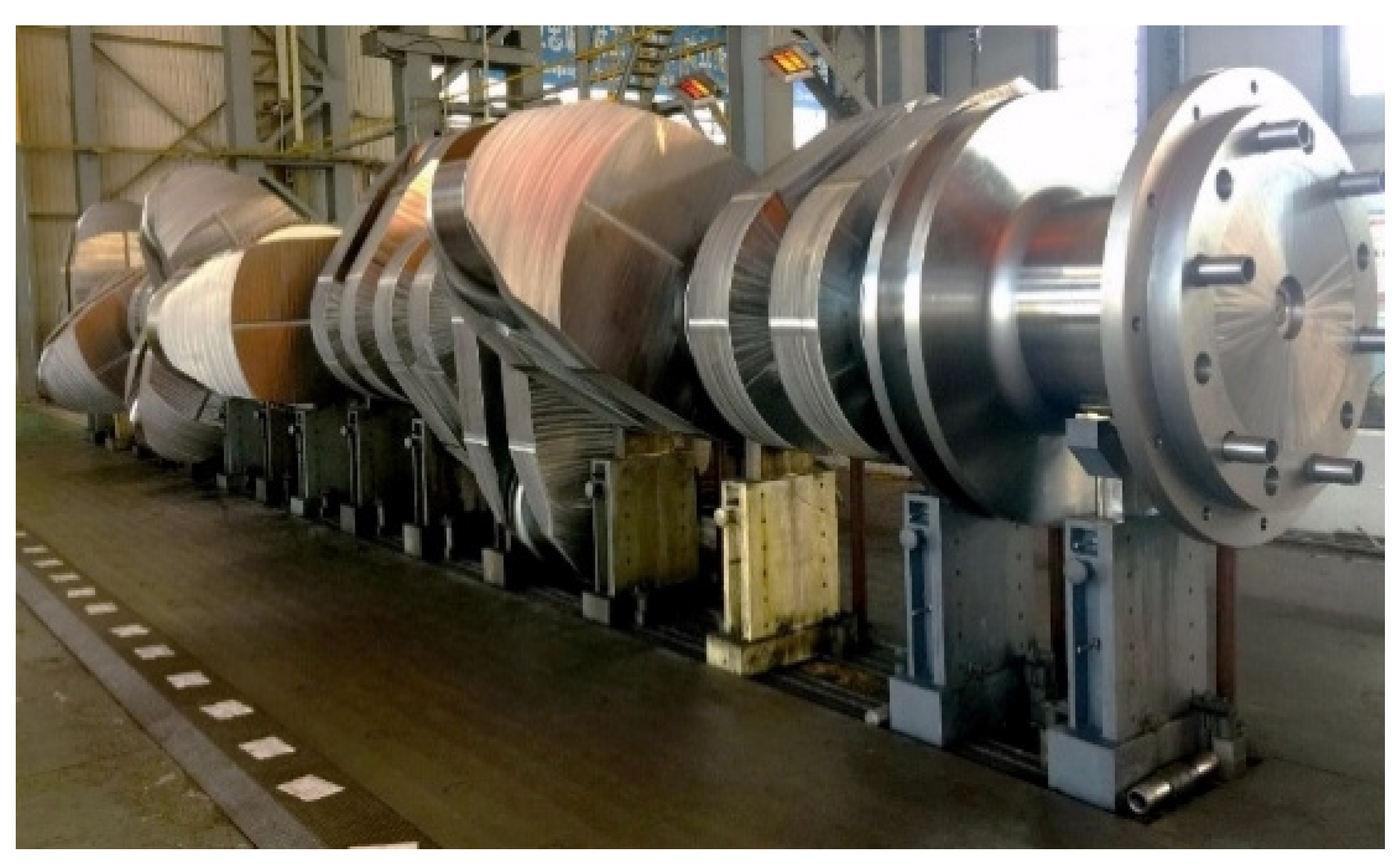
Large marine engine crankshafts, such as the 23-m-long S90 semi-built crankshaft shown in Figure 1, can weigh up to 460 tons and are challenging to manufacture as a single piece. Consequently, engine manufacturers have categorized crankshafts into the following four types:
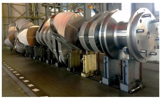
Figure 1.
S90 semi-built crankshaft.
Solid-Built Crankshaft. The entire crankshaft is made from a single piece. This design provides excellent grain flow characteristics compared to other types, resulting in significantly better fatigue resistance. However, main engines on ships are too large to use this type of crankshaft, so it is typically employed for smaller engines. Additionally, due to its high rigidity, the solid-built crankshaft cannot accommodate small misalignments.
Fully-Built Crankshaft. All parts of the crankshaft are manufactured separately through casting or forging and then machined before being assembled using shrink fitting [2]. These crankshafts exhibit good build quality and surface finish, however, their fatigue strength is low due to uneven grain flow.
Welded Crankshaft. This type is gradually becoming the preferred choice for large marine engines. There are two manufacturing methods for producing welded crankshafts: (i) welding crank arms (consisting of half the main journal, half the crank pin, and one crank web) at the pin and the middle of the bearing journal, and (ii) welding the main journal to a single forged crank throw piece. Welded crankshafts provide an optimal solution in terms of cost, strength, and weight.
Semi-Built Crankshaft. This is currently the most popular type for large marine engines. It consists of two main components: the journal and the crank throw [3,4]. The forged journal is shrink-fitted into the crank throw, which is a single piece comprising two webs and a pin, forged as one unit. This design improves grain flow. Furthermore, the assembly offers additional flexibility, allowing it to sustain some degree of misalignment.
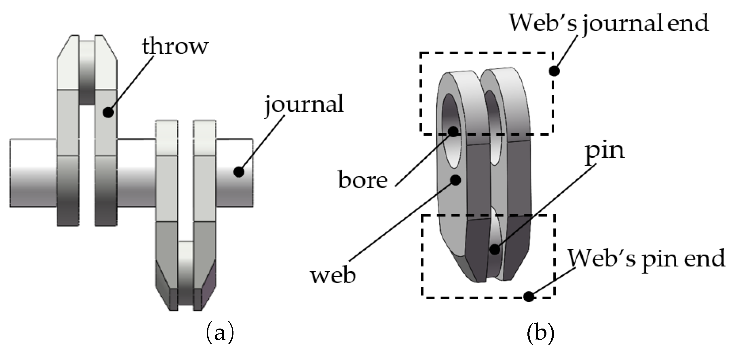
The crank throw, which includes two webs and a crank pin (see Figure 2), is particularly challenging to produce due to its complex shape, substantial weight, and stringent performance requirements arising from demanding operating conditions [5].
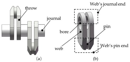
Figure 2.
(a) Section of the S90 crankshaft, and (b) description of the crank throw and pin.
Traditionally, manufacturers produced crank throws directly from a forged block using the Block method. Later, the so-called Ring method was developed, which begins with a hollow ingot or a punched billet [6]. By expanding the hole and flattening the ring, two throws can be obtained by cutting it in half. The Block method is clearly machining-intensive, cost-ineffective, and results in throws with discontinuous grain flow. While the Ring method achieves continuous grain flow and a comparatively high material utilization rate, it is too complicated to implement [7].
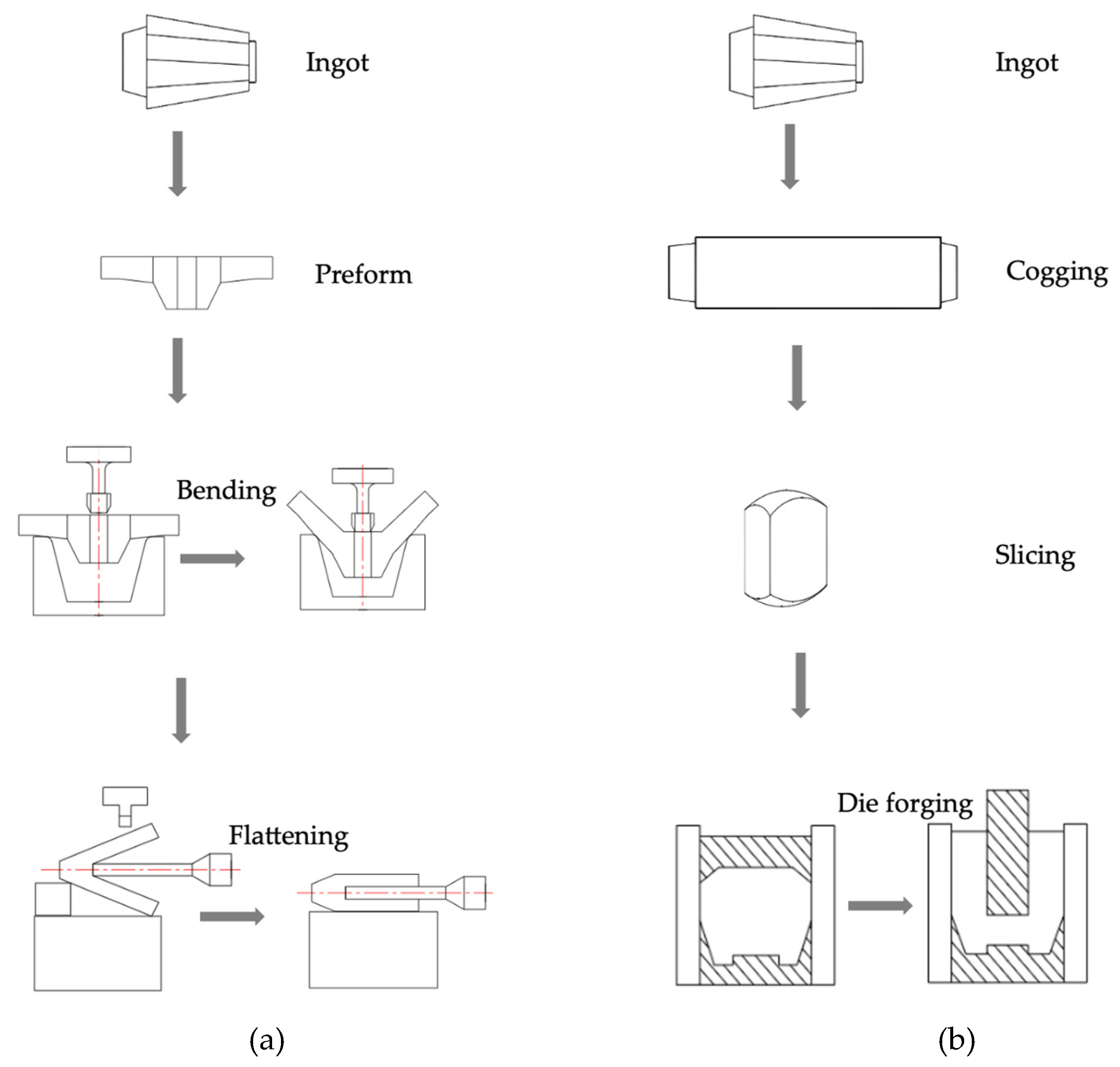
Currently, the two primary methods for forging crank throws are Bend Forging [8] and Die Forging [3,9], as illustrated in Figure 3. In the Bend Forging method, a preform with a specific design is bent into a V-shape and then flattened to create a crank throw forging. The Die Forging process, developed by Kobe Steel in Japan, involves inserting a round bar into a die and forming the crank throw through backward extrusion.
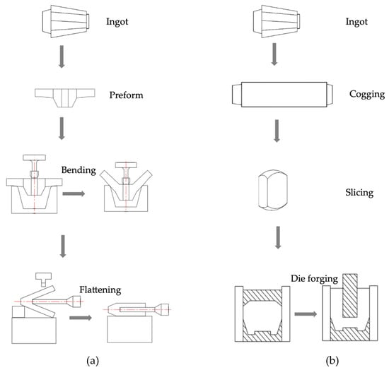
Figure 3.
Processes for (a) Bend Forging, and (b) Die Forging [4].
While both methods produce crank throw forgings that meet technical requirements, each has its limitations. The bend forging method results in large material allowances and requires extensive subsequent machining. Its efficiency is notably low, and the quality of the products is highly dependent on the operator’s skill, making consistent near-net shape production a significant challenge [9]. On the other hand, Kobe Steel’s die forging method faces difficulties in centering the block within the die and requires high press capacity. The high load requirements inherent to this method limit its application, particularly for large parts [10,11,12]. However, Kobe Steel’s method is a Near-Net Shape (NNS) forging process that aims to produce components closely resembling the final shape, thereby reducing material waste and machining time.
Crankshafts are subjected to continuous cyclic loads during operation and static loads when at rest. The demanding service environment is carefully considered when designing crankshafts and selecting their materials. The choice of material depends on factors such as crankshaft design, geometry, and engine type. In any case, crankshafts must possess high strength. Fully-built and semi-built crankshafts are typically made from normalized unalloyed carbon steel. For welded crankshafts, the preferred materials are hardened and tempered low-alloy chrome–molybdenum steel or normalized low-carbon manganese steel. In this study, S34MnV steel is used for both the simulations and the experiments.
S34MnV steel is a low-alloy steel that has been extensively studied [13,14,15,16,17]. Due to its excellent comprehensive mechanical properties achieved through quenching and tempering, it is widely used in the manufacturing of large marine crankshafts, including both journals and throws [18]. Its mechanical properties are presented in Table 1, and its composition is provided in Table 2 [19].

Table 1.
Mechanical properties of S34MnV steel.

Table 2.
Chemical composition of S34MnV steel (in weight percent).
Recent advancements in numerical modeling and simulation techniques have significantly improved our ability to analyze and optimize forging processes for crankshaft throws. These simulations accurately predict forging loads and key microstructural data, such as grain characteristics, which are directly influenced by the forging process. Experimental testing complements these simulations by providing real-world data to validate and refine computational models. These findings highlight the importance of integrating simulation and experimental approaches to optimize forging processes.
The finite element method (FEM) is a powerful and advanced tool in scientific research. Many scholars have used FEM to study metal-forming processes. Jayanthi et al. utilized FEM to optimize forging process sequences for compressor discs, analyzing force, temperature, strain, and material properties [20]. Raja et al. employed Deform-3D and 3D processing map to study microstructural and mechanical characteristics of hot worked homogenized AA7068 [21]. Zeng et al. simulated the hot forging of high-Mn steel turnout cores, obtaining optimal parameters through systematic analysis [22]. Zhang et al. applied repeated continuous extrusion forming to Al–Mg–Si–Cu alloys, investigating deformation behavior, microstructural evolution, and material properties. Their results revealed enhanced tensile strength and elongation with uniform grain size [23]. The numerical simulations in these studies were consistent with physical experiments, demonstrating that simulating forging processes can significantly reduce the need for extensive physical trial and error, thereby lowering development costs.
The global demand for large marine crankshafts is expected to grow steadily in the coming years, driven by several factors: the expanding marine engine market, increasing maritime trade, a focus on fuel efficiency, stricter environmental regulations, and the growth of low-speed engines. Semi-built crankshafts offer a good balance between strength and ease of manufacture for larger engines, making them a cost-effective choice for large marine applications.
The cost of the forging process for large maritime crankshaft throws is influenced by several factors: material costs, equipment investment, energy consumption, labor costs, quality control and certification, and research and development. Forging is a capital-intensive process, however, the resulting near-net-shape forgings provide benefits such as reduced material waste, improved strength, and potential weight savings, which can offset the initial manufacturing costs over the component’s lifecycle. This research uses an S90 marine crank throw as a case study to identify the optimal forging process.
2. Objective of the NNS Forging of a Large Marine Crank Throw
As shown in Figure 2, a U-shaped marine crank throw comprises two webs and a pin. A main journal is shrink-fitted into the web bore. For convenience, the boxed upper side of the throw in Figure 2b is referred to as the journal end of the web, as this is where the main journal will be shrink-fitted. The crank throw’s operating conditions and assembly requirements demand that this end have a semicircular shape. The lower side, termed the pin end, is so named due to its proximity to the crank pin. To reduce the mass of the rotating part, the pin end is designed with a conical surface. The middle section of the web has a rectangular cross-section to transmit high torques.
The gap between the two inner faces of the webs is very narrow, typically narrower than the thickness of the webs themselves to save space. Additionally, this gap is wide and deep, posing significant challenges for forging. Another obstacle is the lack of rolled billets suitable for forging large, heavy crank throws. As a result, the complete workflow for manufacturing crank throws involves the following steps: smelting → ingot casting → heating → open-die forging billets → heating → surface cleaning → NNS forging of crank throws → heat treatment → machining [24].
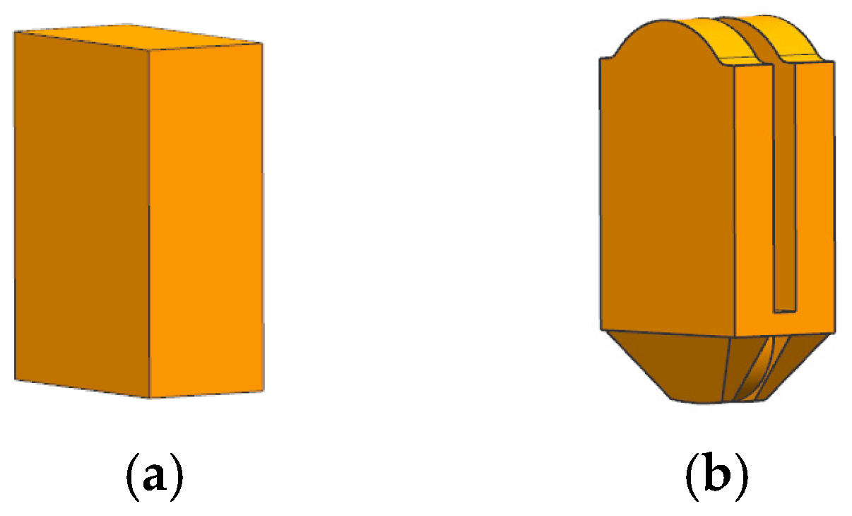
From Figure 2, it is evident that if web bores could be produced directly during the NNS forging process, significant material savings and machining hours could be achieved. However, due to the limitations of conventional presses, it is currently very difficult to form the bores directly through forging, necessitating machining instead. Consequently, the NNS forged crank throw design should resemble that shown in Figure 4b. The billet shape should closely approximate the final forged throw to streamline the process. A rectangular parallelepiped billet, as shown in Figure 4a, is ideal for this purpose, as it is easy to forge and facilitates surface cleaning.
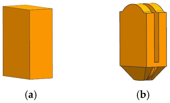
Figure 4.
Expected (a) billet and (b) near-net forged throw.
3. Analysis of NNS Forging Methods of Crank Throw
As described in Section 1 and Section 2, the shape characteristics of crank throws make extrusion the most suitable method for producing forged throws. In this section, three NNS extrusion methods are designed and analyzed using numerical simulation, followed by a comparison to identify the optimal process.
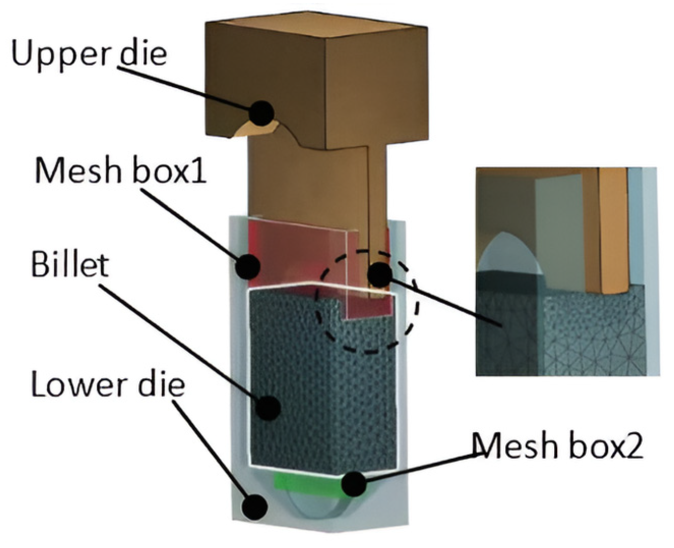
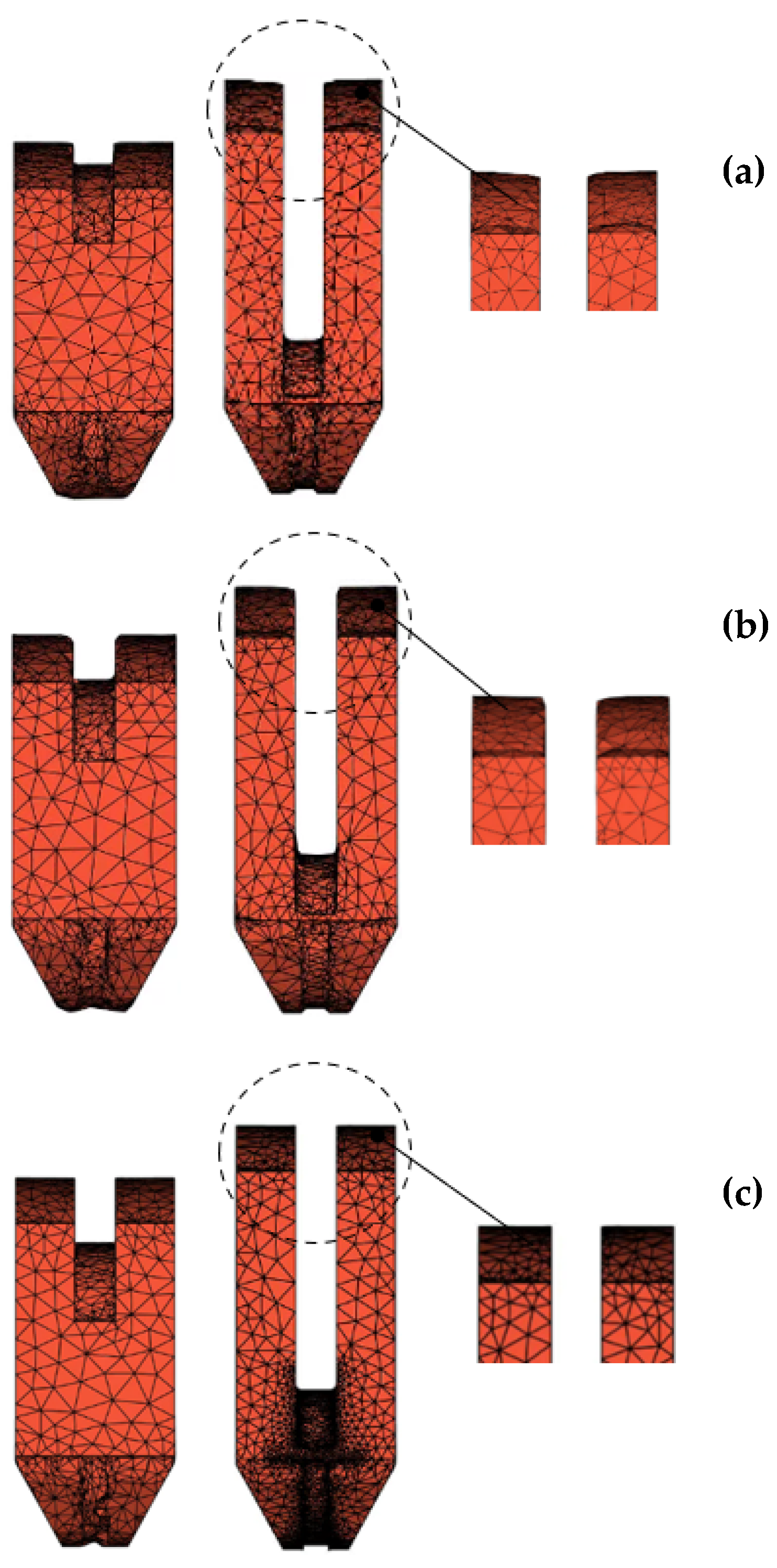
The leading metal forming software, Forge® (version3.1, Transvalor S.A., Biot, France), was used to simulate the various NNS forging processes of the crank throws. Figure 5 illustrates the finite element models, which include the billet, the upper die, and the lower die. Both dies are assumed to be ‘rigid’ (i.e., non-deformable), while the billet is considered deformable. At the start of the simulation, the billet is meshed with 30,000 tetrahedron elements. To maintain accuracy and optimize computational time, the mesh box technique was employed. This technique controls mesh refinement in highly deformed zones, as indicated by boxes 1 and 2 in Figure 5.
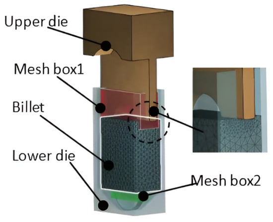
Figure 5.
Finite element model of crank throw extrusion.
An Arrhenius equation model (see Equation (1)) was used to accurately predict the rheological stresses generated during deformation [6]. The model for S34MnV steel was implemented in the software code through a subroutine.
where is the Strain Rate, is the Flow Stress, R is the Universal Gas Constant, and T is the Temperature. The Activation Energy for S34MnV steel is 321,943 kJ/mol.
Other process parameters for the simulations are listed in Table 3.

Table 3.
Process parameters.
3.1. One-Step Extrusion (OSE)
3.1.1. Numerical Simulation and Analysis of OSE
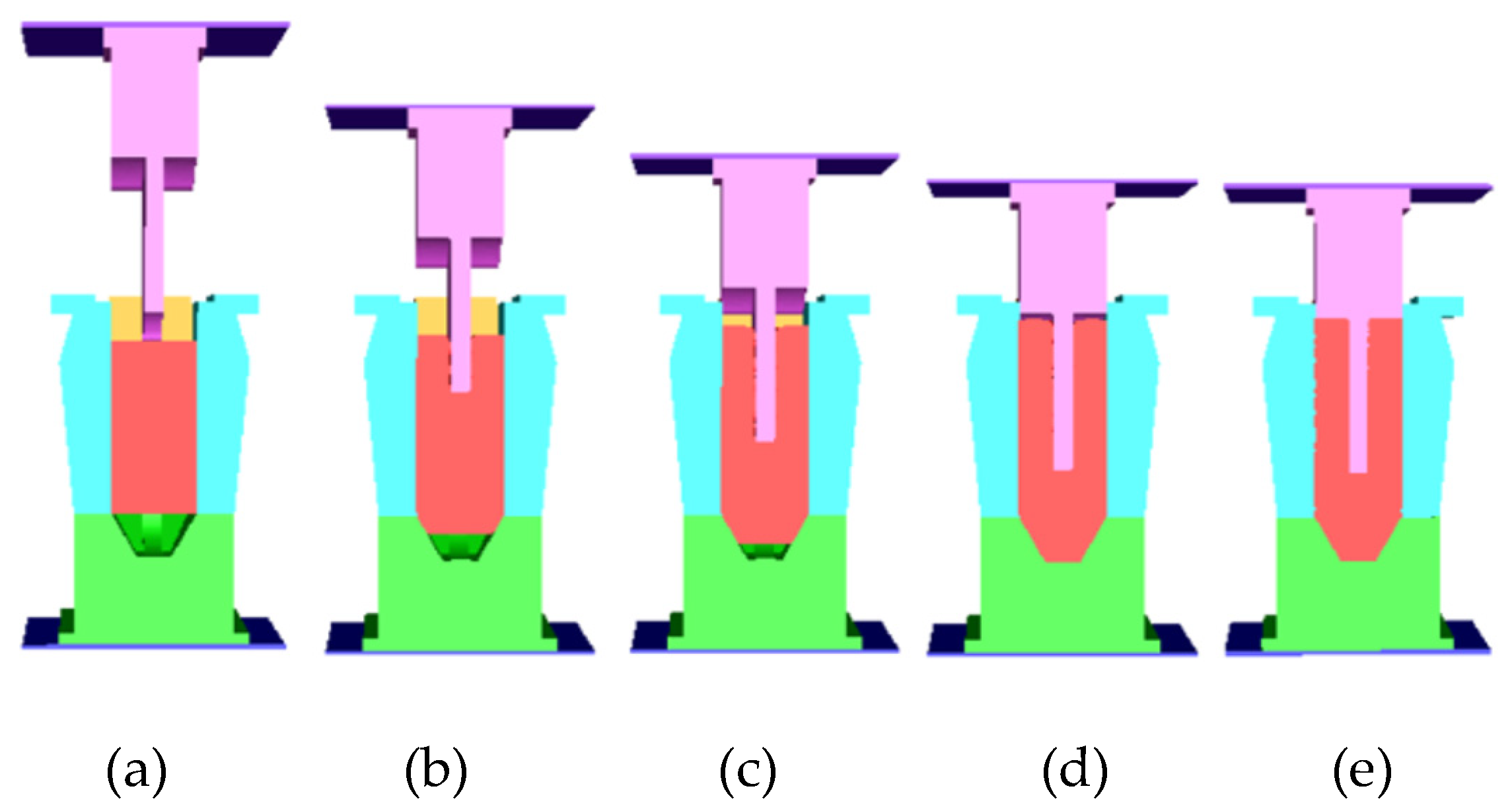
Figure 6 shows a simulation of the OSE process for a crank throw. Extrusion begins immediately when the punch contacts the billet, as the billet’s cross-section closely matches that of the die cavity. This process involves combined extrusion, with both ends of the billet deforming simultaneously. Figure 6b shows the backward extrusion at the upper end and the forward extrusion at the lower end. When the punch stroke reaches 95% (Figure 6d), the pin-end die cavity is fully filled, marking the end of the combined extrusion phase and the beginning of backward extrusion at the upper end. Finally, the material flows upward, completely filling the die cavity to form the journal end (Figure 6e).
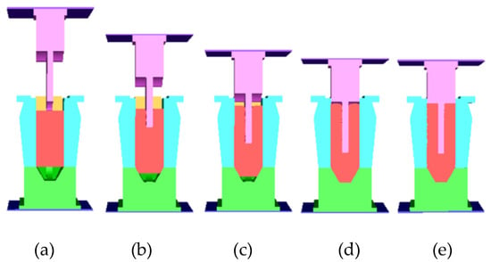
Figure 6.
One-step extrusion: (a) 0%
stroke, (b) 20% stroke, (c) 80% stroke, (d) 0% stroke, and
(e) end stroke.
3.1.2. Influence of Asymmetrically-Placed Billets
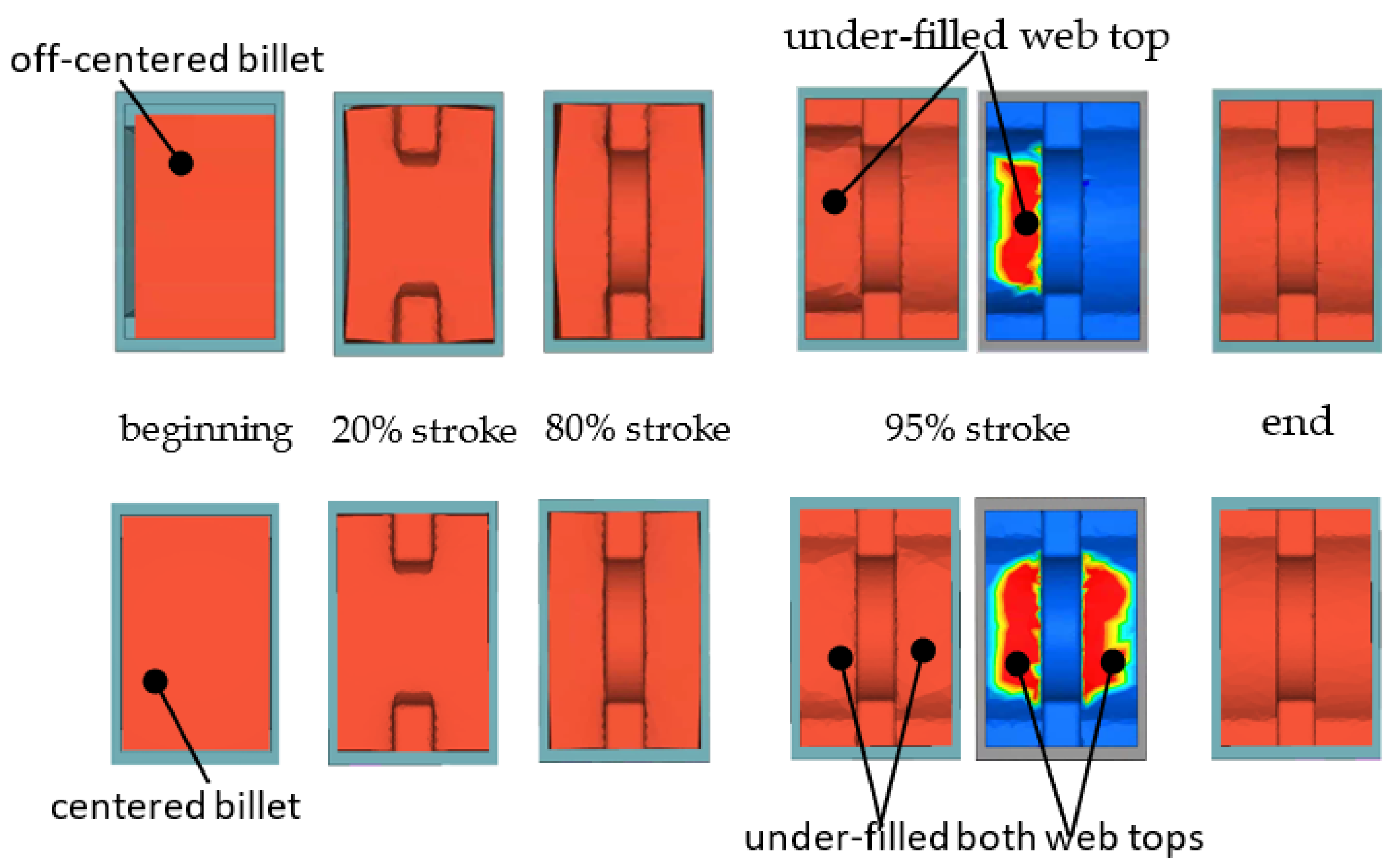
In real production, to facilitate the billet’s entry into the die cavity, its cross-section must be slightly smaller than the die cavity. For large billets, the gap between them can be as wide as 50 mm or more. In most cases, the billet is not perfectly centered within the die cavity. Figure 7 illustrates the OSE process for both a centered billet and an off-centered billet.
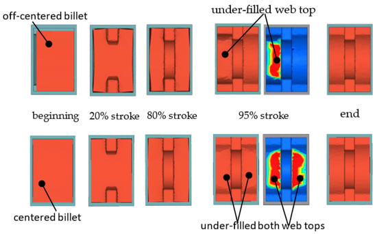
Figure 7.
OSEs with off-centered and centered billets.
At the end of forging, both cases produce good crank throw forgings. However, when the billet remains centered throughout the process, its deformation is symmetric. In the case of an off-centered billet, the right web forms better than the left during most of the stroke. At 95% stroke, the right web is already fully formed (represented in blue), while the left remains under-filled (area represented in red). This asymmetry leads to differences in the required loads.
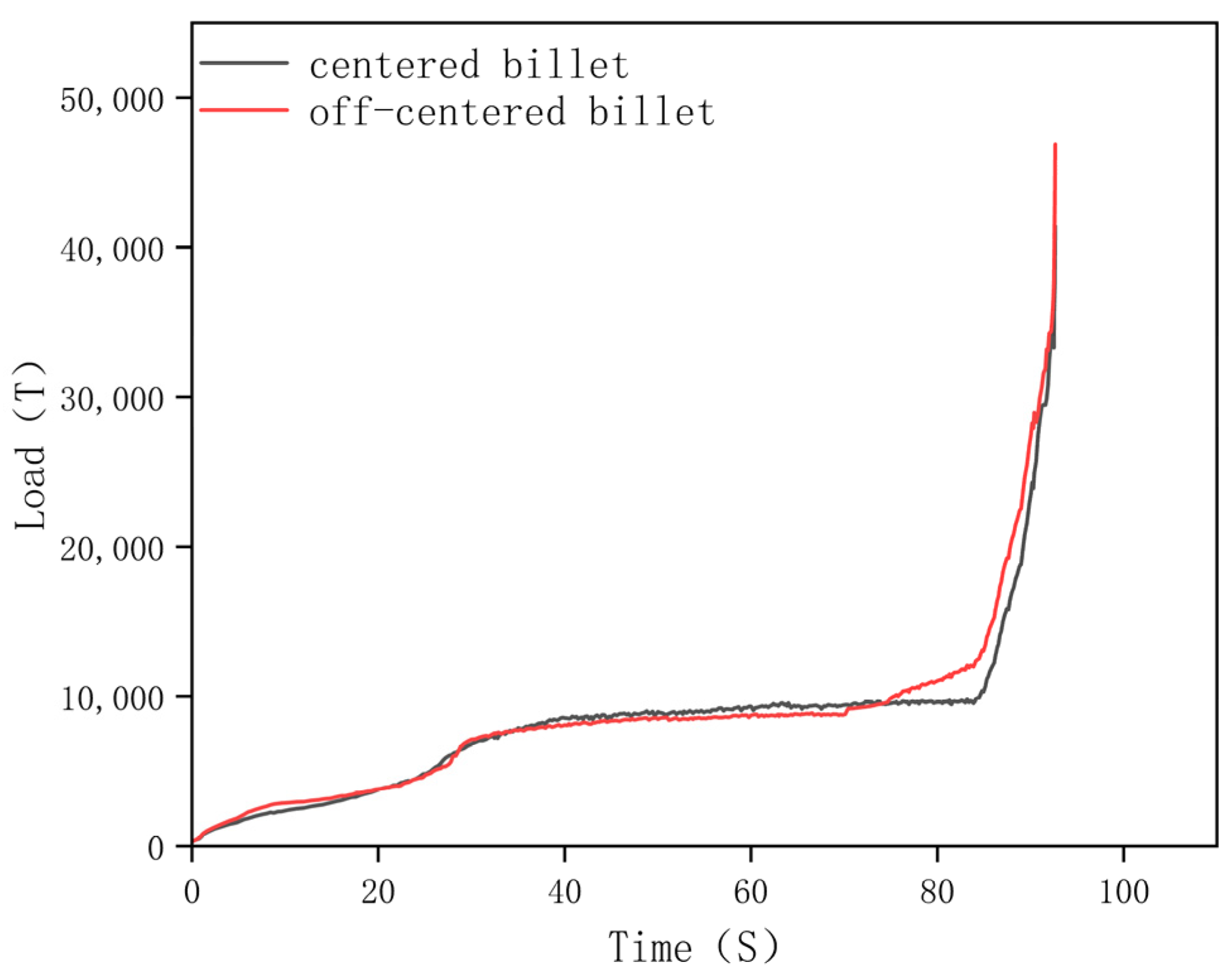
Figure 8 shows the load-time curves for both cases. The load curves are nearly identical except at the end of the forging process. In the off-centered billet case, additional force is required at 95% stroke to push the material from the right side to the left, ensuring the left web fully fills the die cavity. The maximum load for a centered billet is 41,000 tons, whereas for an off-centered billet, it reaches 49,000 tons.
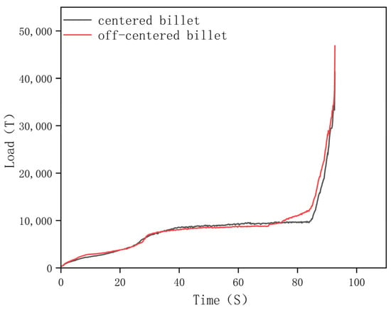
Figure 8.
Load-time curves for extrusion with off-centered billet and centered billet.
This indicates that to reduce the load and achieve high-quality crank throw forgings, it is crucial to ensure the billet is centered at the start of the process. If the billet begins off-centered, implementing an automatic method to reposition it to the center is necessary.
3.2. Upsetting/Backward Extrusion (U/BE)
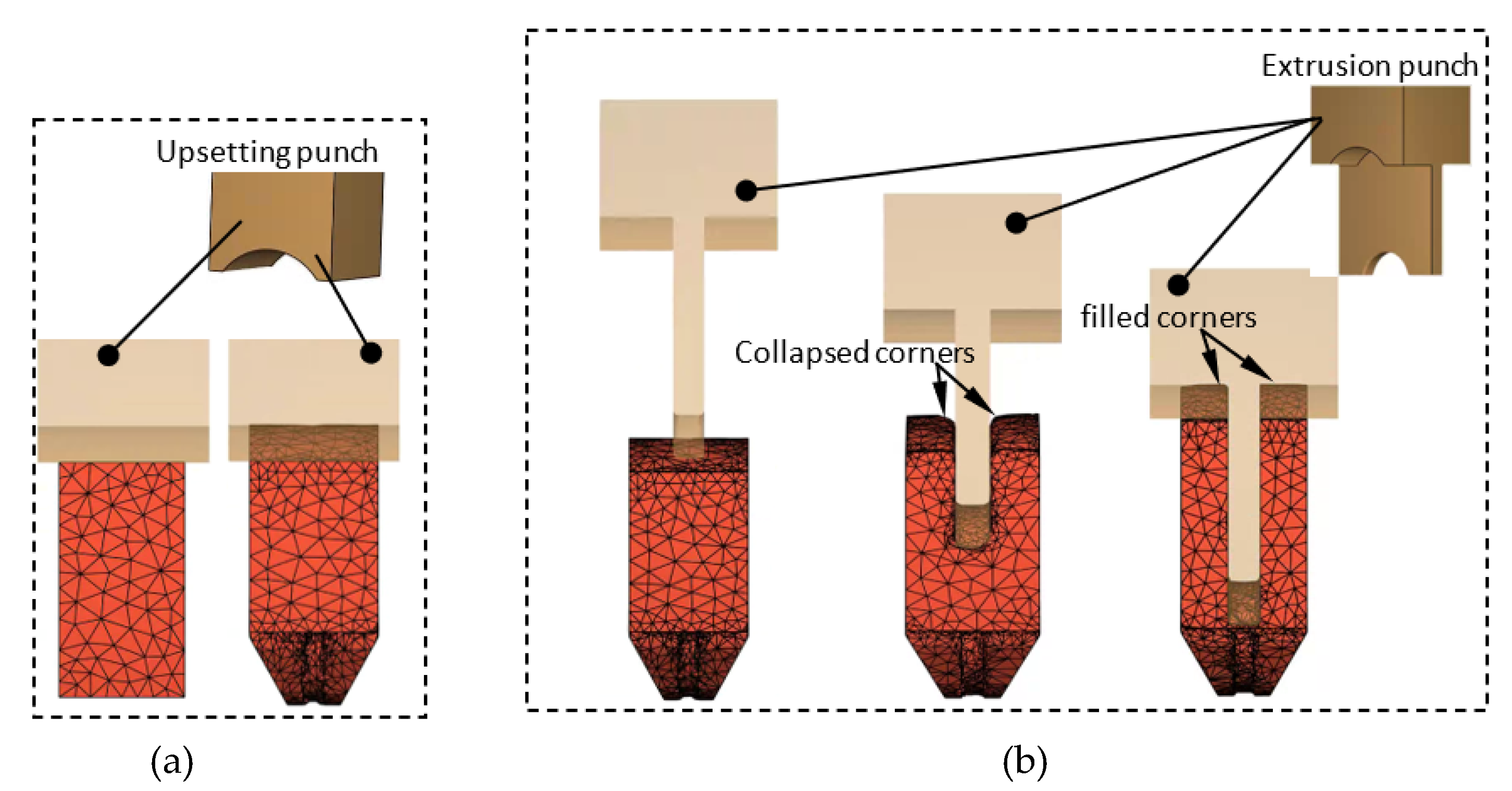
Figure 9 illustrates the U/BE process for a crank throw, where an upsetting step is incorporated to ensure the billet is centered in the die. In this method, during the upsetting stage, an upsetting punch with an end face matching the shape of the webs is used. The billet undergoes closed-die upsetting at this stage, followed by backward extrusion using an extrusion punch.
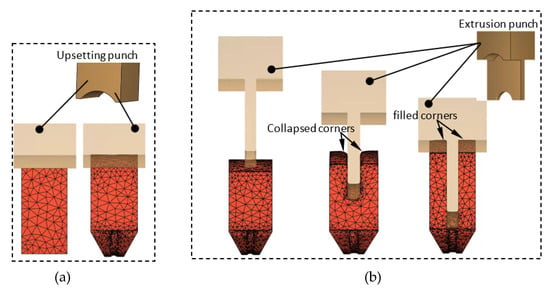
Figure 9.
Upsetting/backward extrusion of the crank throw. (a) Upsetting and (b) Backward extrusion.
During the upsetting stage, the billet is not only aligned to the die center but also shaped at both ends of the throw under high temperatures. This approach effectively reduces the load required during the subsequent backward extrusion phase.
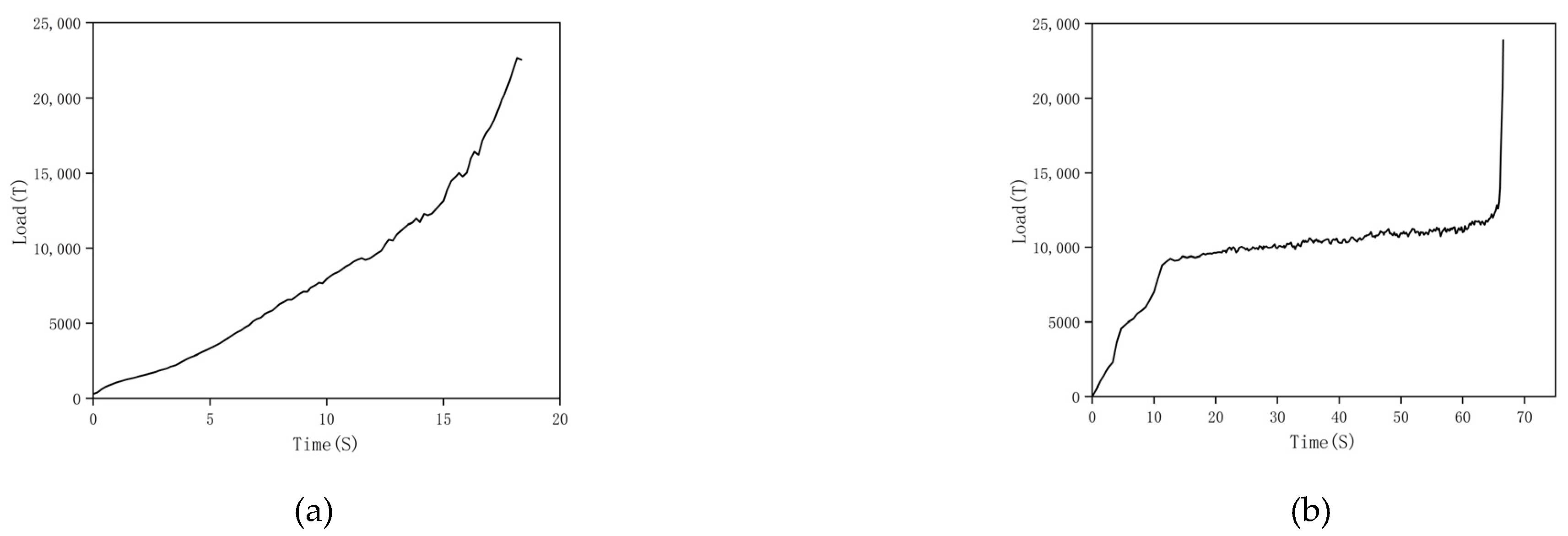
Figure 10 shows the load-time curves for the upsetting/backward extrusion process. During the upsetting step, the load increases at an approximately constant rate, except for a sharp rise at the end of the stage when both ends of the throw are fully formed (see Figure 9b). In the subsequent backward extrusion step, the load initially rises rapidly, then stabilizes for most of the extrusion process. However, toward the end, the load increases steeply.
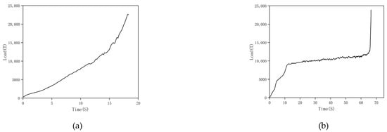
Figure 10.
Load-time curves for the upsetting/backward extrusion. (a) Upsetting and (b) Backward extrusion.
This sharp rise occurs because a very high load is required to eliminate the collapsed corners on the web tops (see Figure 9b), which are caused by friction between the extrusion punch and the inner sides of the web tops. Additionally, to accurately form the top end of the web, the extrusion punch must match the shape of the corresponding part of the web. These curved surfaces are complex to manufacture, significantly increasing production costs.
Furthermore, due to the backward extrusion punch’s length being much greater than its thickness, deflection can occur at the beginning of the extrusion process, leading to unequal web thicknesses. To address these challenges and ensure better outcomes, an improved process must be developed.
3.3. Grooving–Upsetting/Backward Extrusion (G–U/BE)
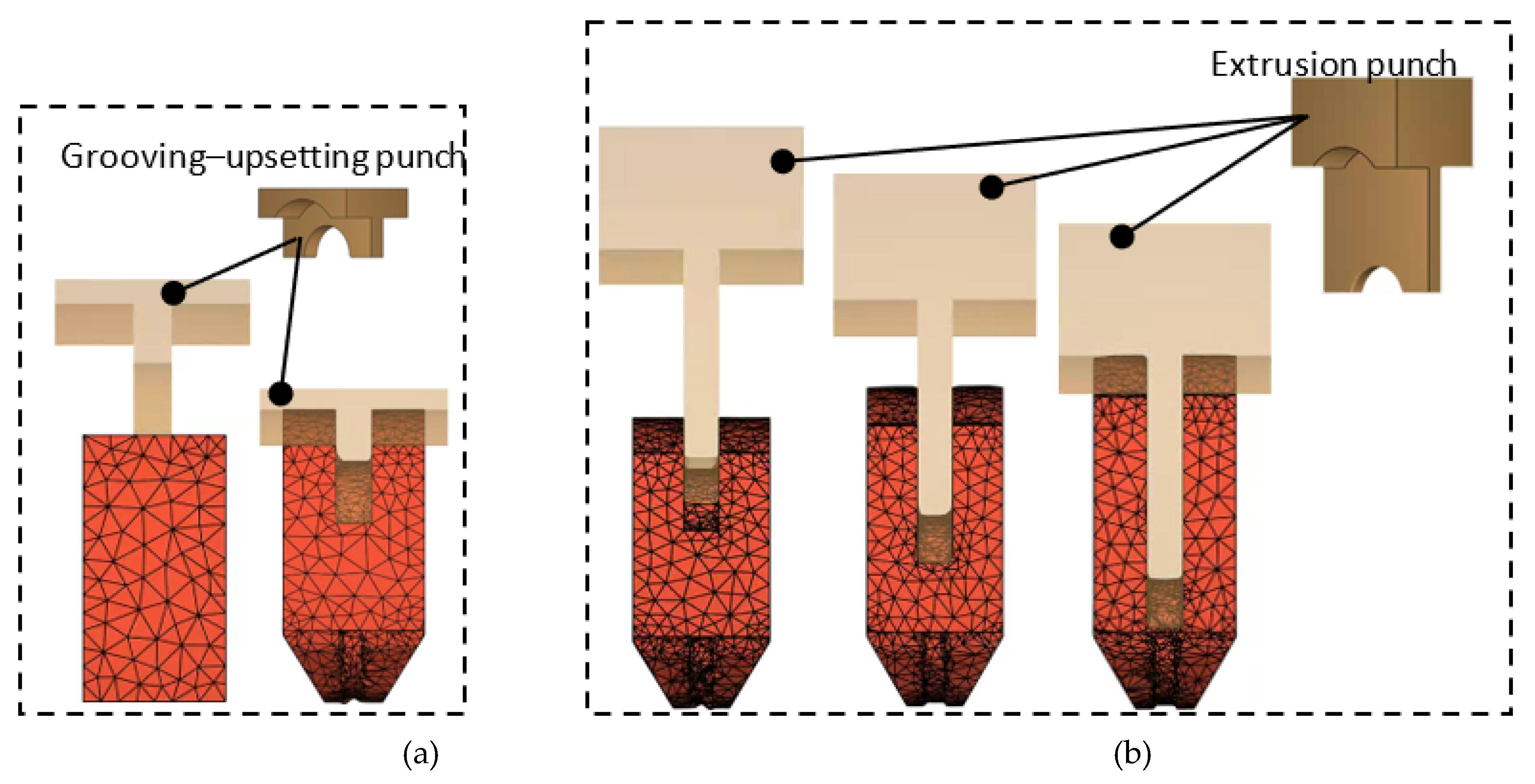
Based on the U/BE process, a groove (actually obtained through backward extrusion) is added during its upsetting step. Grooving–upsetting is a combined extrusion process, as shown in Figure 11. The principle is that after the billet is placed into the die cavity, it is first pressed by a punch with a “tongue” extending from its end face. The deformed billet is shown in Figure 11b at the end of grooving–upsetting. This process retains the advantage of ensuring the billet remains centered, as in the U/BE process. It not only forms the two web ends and the crank pin end but also produces a shallow guiding groove that serves to correctly position the extrusion punch for the subsequent backward extrusion, which helps control the web thickness variation.
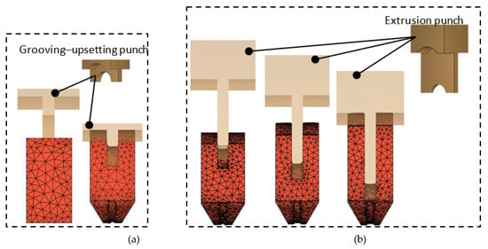
Figure 11.
Grooving–upsetting/backward extrusion of the crank throw. (a) Grooving–upsetting and (b) Backward extrusion.
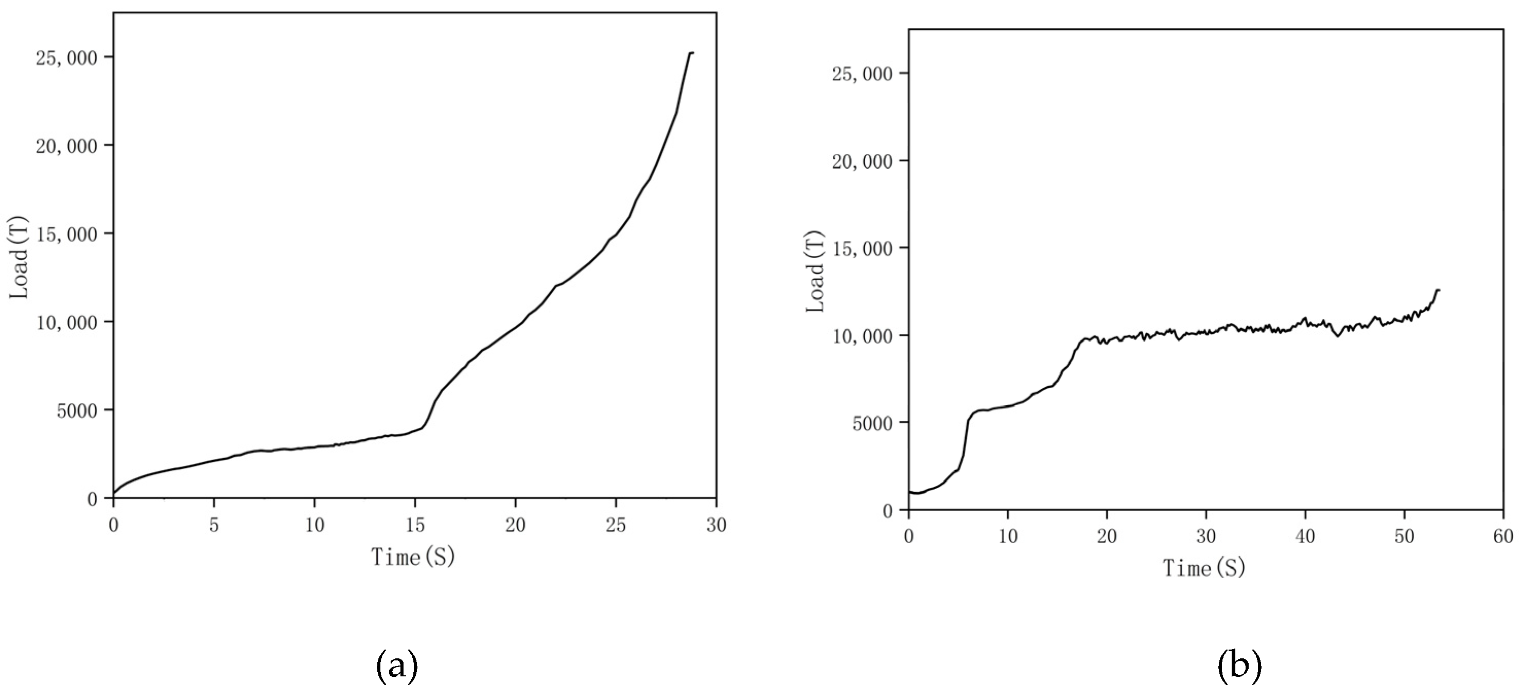
The load-time curves for the G–U/BE process are shown in Figure 12. It can be seen that the curves for the grooving–upsetting step (Figure 12a) and the upsetting step (Figure 10a) are similar, except that the grooving–upsetting step requires a lower maximum load, indicating that the groove helps reduce the load. The load-time curves for both processes at the backward-extrusion step (Figure 10b and Figure 12b) are also similar, as they both increase rapidly initially and level off at around 10,000 tons. The notable difference is that the load in the U/BE process increases steeply towards the end, while in the G–U/BE process, there is only a slight increase in load at the end. This is because, with an appropriate groove depth, the subsequent backward extrusion has little effect on the shape of the web ends produced in the grooving–upsetting step. Hence, unlike U/BE, there is no need for closed-die forming to eliminate collapsed web corners, and no very high load is required. Additionally, the extrusion punch for the G–U/BE process can be much simpler than that used in U/BE, since the web ends are already completed in the preceding grooving–upsetting step.
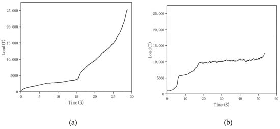
Figure 12.
Load-time curves for the grooving–upsetting/backward extrusion. (a) Grooving–upsetting and (b) Backward extrusion.
3.4. Determination of the Optimal Method
3.4.1. Forging Load
Forging load is usually an important indicator for evaluating a forging process, and it directly impacts the cost of the press, energy consumption, and tool life. The maximum loads for each step of these three methods are listed in Table 4. As shown in Table 4, G–U/BE results in the lowest load.

Table 4.
Loads of each operation in different methods for the S34MnV steel.
3.4.2. Comparison of Forging Forming Quality
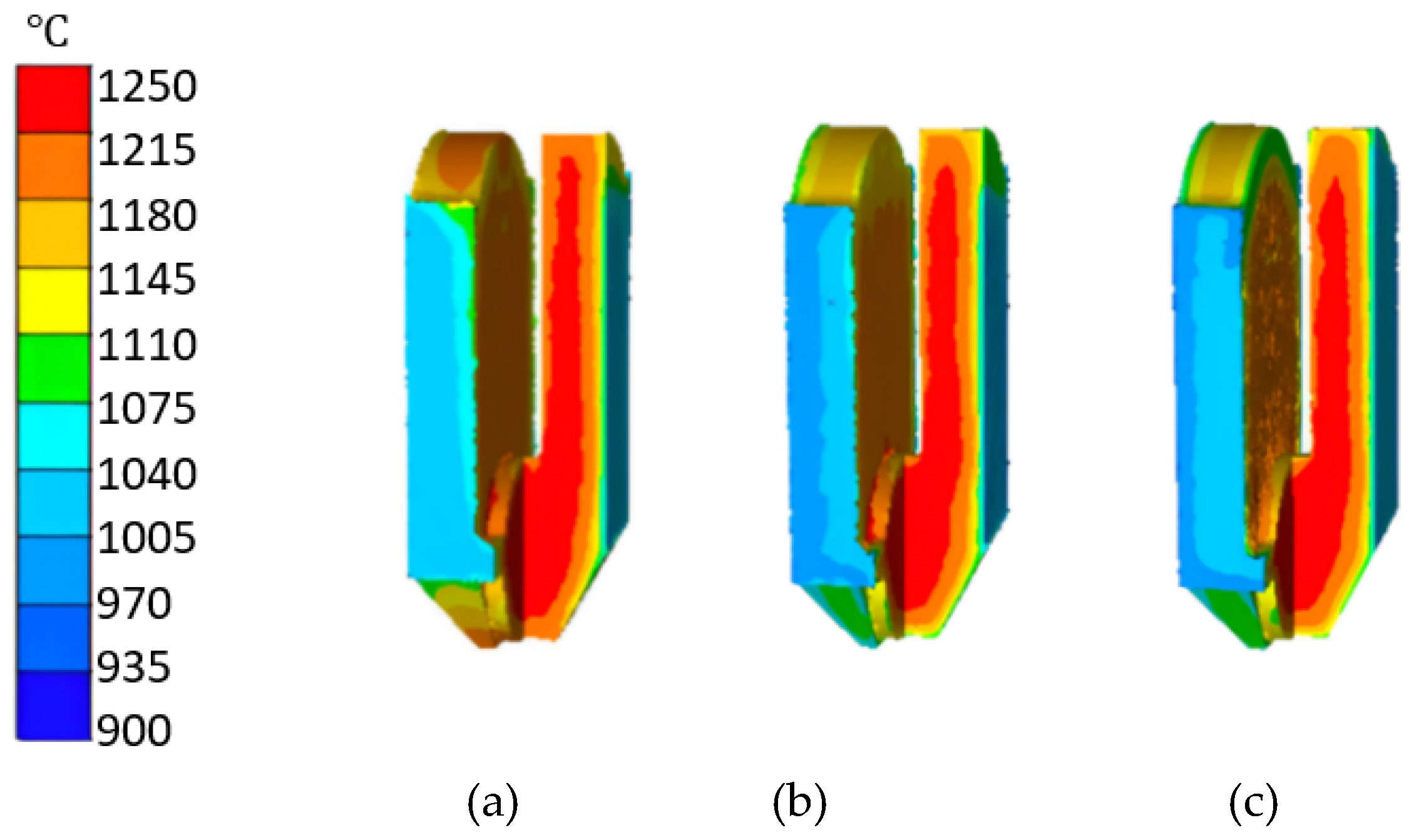
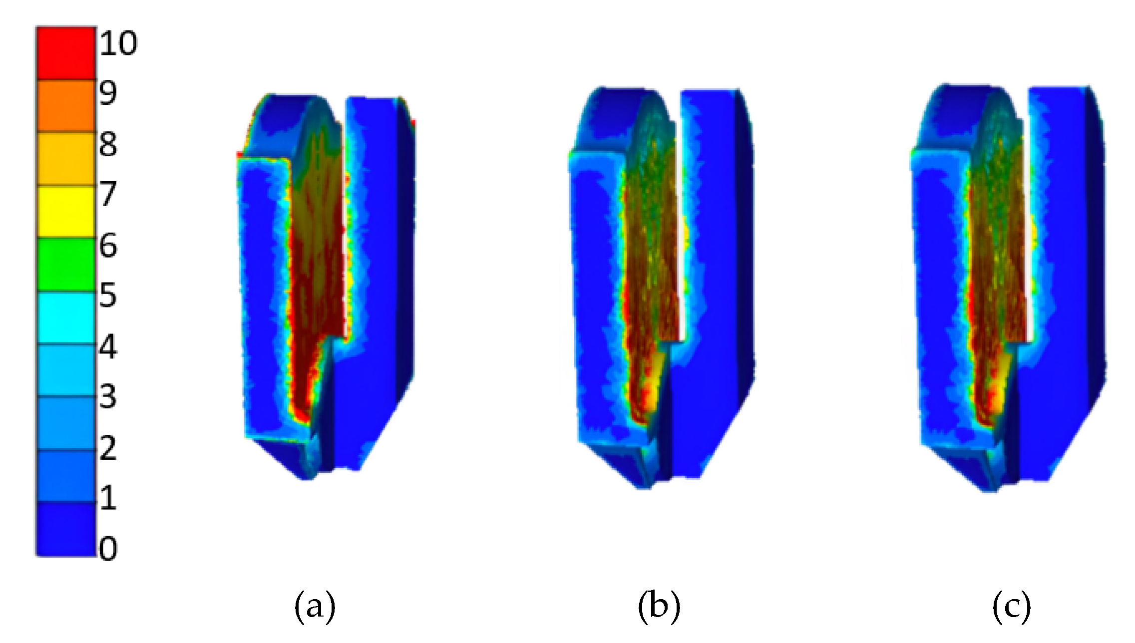
At the end of a forging process, the product’s temperature and its equivalent strain are two key factors affecting the forging’s microstructure. A high final forging temperature tends to cause grain growth. Although deformation can refine the grains during the forging process, if the forging temperature is too high, the previously refined grains tend to coarsen, resulting in lower properties of the forging [11]. Figure 13 and Figure 14 show the temperature fields and equivalent strain fields of the forged throw at the end of the three methods, respectively. It is clear that they are essentially the same.
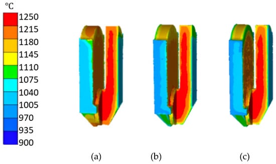
Figure 13.
Final forging temperatures. (a) OSE, (b) U/BE, and (c) G–U/BE.
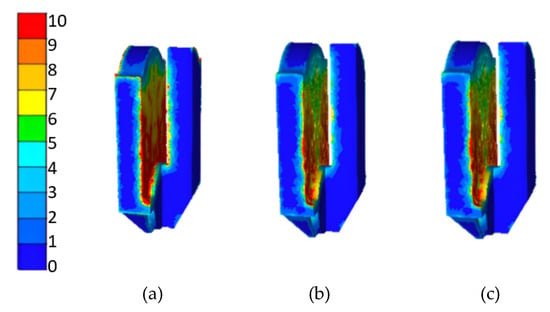
Figure 14.
Equivalent strains (unitless). (a) OSE, (b) U/BE, and (c) G–U/BE.
Numerous studies have indicated that the billet’s temperature and equivalent strain are key factors influencing the forging’s microstructure [25,26,27,28]. Therefore, it can be concluded that the microstructures of the forgings produced by the three methods are also similar.
3.4.3. Comparison of the Temperature Rise of the Lower Die
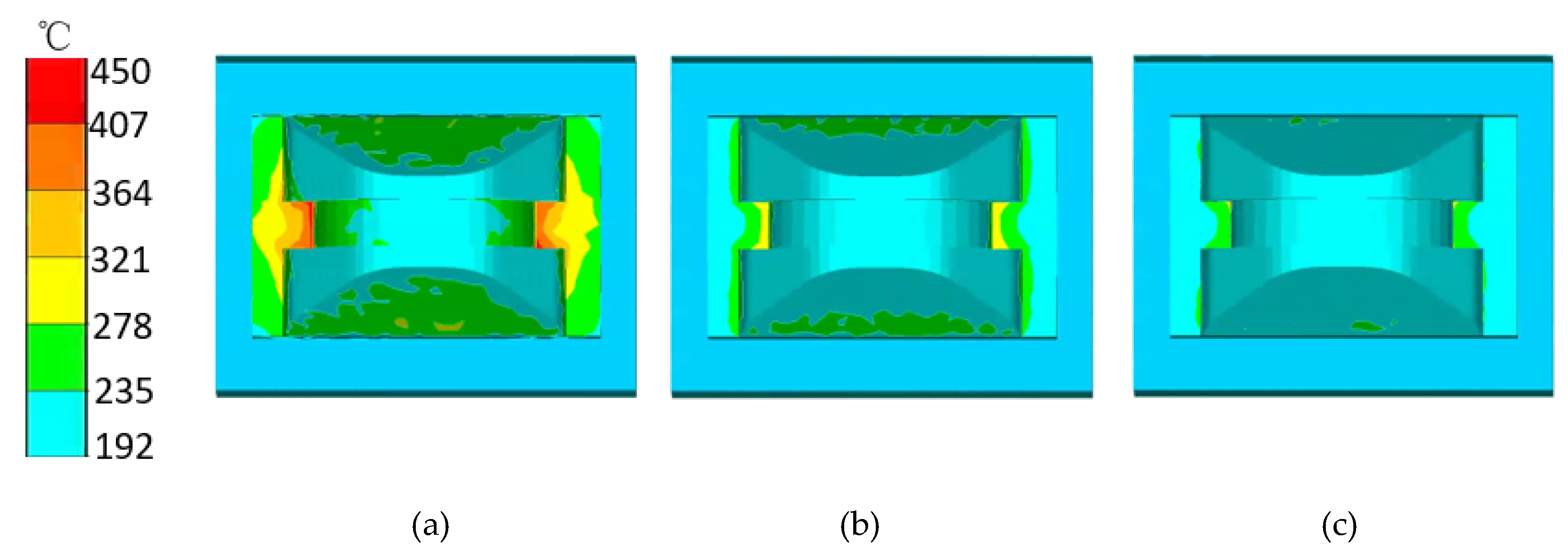
The die’s temperature is the most important factor influencing its life. Elevated die temperatures can seriously affect its hardness and mechanical properties, resulting in a decrease in its ability to resist deformation and wear [7]. Among the three methods, the lower die has the longest contact time with the billet, and thus, it reaches the highest temperature at the end of the process. Figure 15 shows the lower die’s temperature fields at the end of the three processes, and their highest temperatures are listed in Table 5. It can be seen that the temperature of the lower die in OSE is the highest, while those in U/BE and G–U/BE are basically the same.
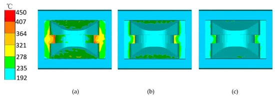
Figure 15.
Lower die temperature at the end of the three processes. (a) OSE, (b) U/BE, and (c) G–U/BE.

Table 5.
Highest temperatures of the lower die at the end of the processes.
4. Study on the Optimal Groove Shape
Based on the above discussion, it is safe to say that G–U/BE is the best method for near-net forging of large marine crank throws. It has four advantages: first, it solves the billet’s initial off-center problem; second, during the subsequent backward extrusion, the groove serves to guide the extrusion punch; third, it improves the shape and size accuracy of the journal ends; and fourth, it lowers the maximum forging load. However, these benefits can only be achieved if the optimal groove shape is selected.
4.1. Selection of the Optimal Groove Shape
The width of the groove is limited by the gap between the webs, leaving only the depth of the groove as a variable. The goal of finding the optimal groove depth is, first, to obtain the required shapes of the journal ends and pin ends at the end of the grooving–upsetting step, and then to ensure that the journal ends remain unchanged as rigid zones throughout the backward extrusion. Obviously, if the groove is too shallow, the rigid zone cannot be formed, and as a result, the subsequent backward extrusion deformation will alter the web end shape. If the groove is too deep, it becomes difficult to prevent the unequal web thickness caused by the off-centered billet. Therefore, there must be an optimal groove depth.
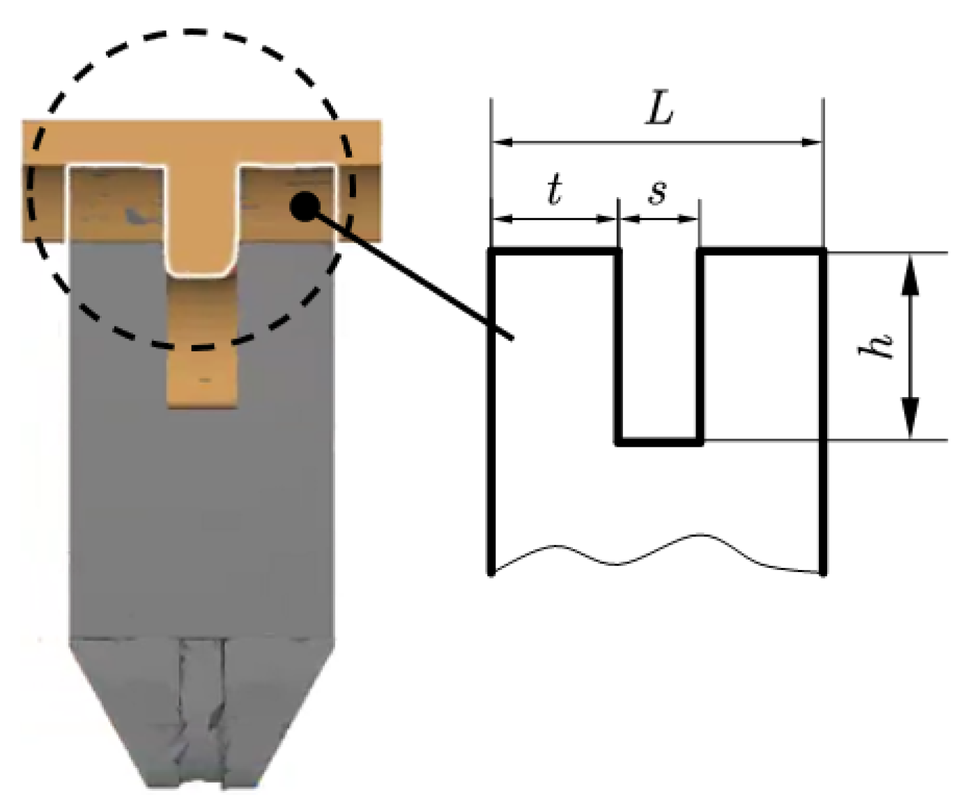
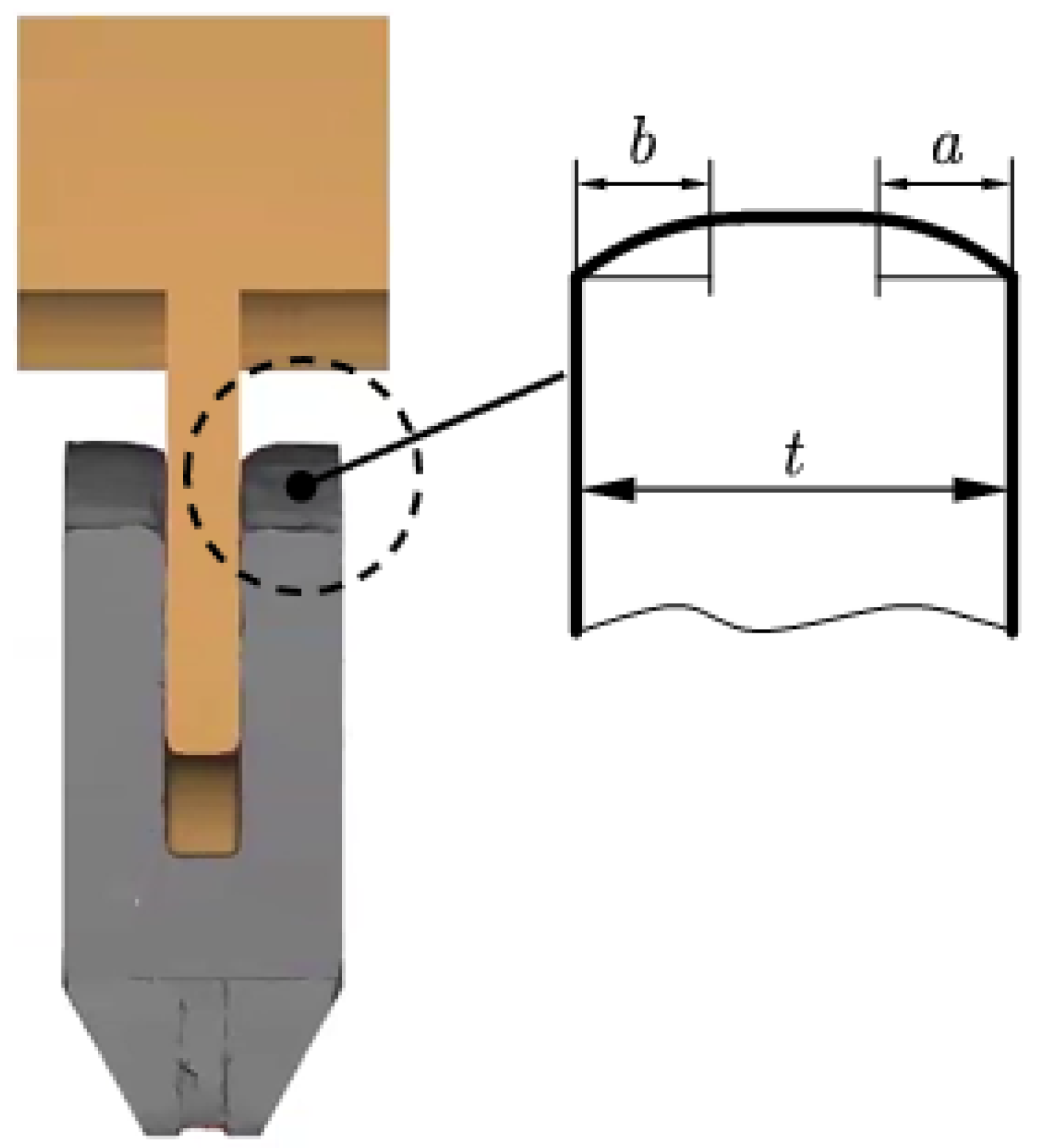
As is known from plastic mechanics, the groove forming can be approximated as a plane strain problem, where the main deformation zone is located beneath the punch. During backward extrusion, under the action of the punch, the metal flows into the two webs. This flow is restricted by the size and shape of the deformation zone, and the characteristics of the deformation zone depend on the web gap width (the punch width) and the thickness of the web. These two dimensions vary with crank throws of different specifications. For convenience, the following two parameters—relative punch width (κ) and relative groove depth (χ)—are introduced, expressed by Equations (2) and (3):
where meanings of are demonstrated in Figure 16.
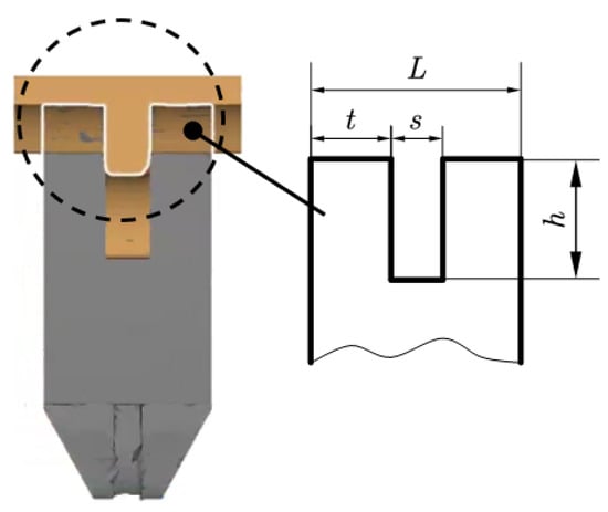
Figure 16.
Billet’s journal end after grooving–upsetting.
4.2. Influence of the Groove Depth (h) on the Shape of the Journal End
According to data from classification societies, the relative width (κ) of marine crank throws ranges from 0.5 to 0.8. Figure 17 shows the journal end shape of the web after backward extrusion. Shape parameters (λ) and (μ) are introduced and expressed by Equations (4) and (5):
where meanings of a and b are demonstrated in Figure 17.
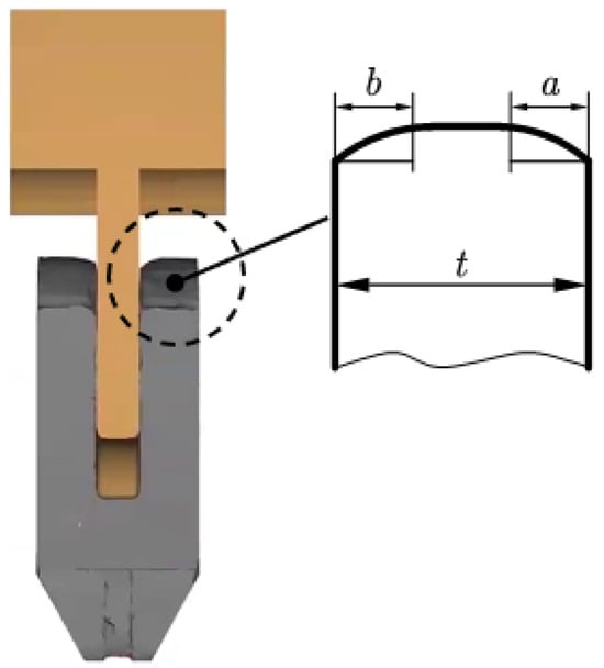
Figure 17.
Billet’s journal end during backward extrusion.
Finite element simulation is employed to find the best combination of χ and κ. As shown in Table 6, since data indicate that the relative width of marine crank throws ranges from 0.5 to 0.8, three values (0.5, 0.65, 0.8) are selected for χ, and four values (0, 0.5, 1.0, 1.5) are selected for κ. Simulations are carried out for combinations of these two parameters. The calculated results for λ and μ are also shown in Table 6.

Table 6.
The influence of the groove depth on the webs’ journal ends’ shape.
It can be seen from Table 6 that when the relative groove depth (χ) ≥ 1.5, the journal end of the web formed during grooving–upsetting remains unaffected during the subsequent backward extrusion. Figure 18 shows a side-by-side view of the journal end shape at the end of grooving–upsetting and at the end of the subsequent backward extrusion with relative groove depths of 0.5, 1.0, and 1.5, respectively. It is clear that with χ equal to or greater than 1.5, there are no obvious collapsed corners at the web’s journal ends, and the well-formed journal end shape remains unaffected during the following backward extrusion.
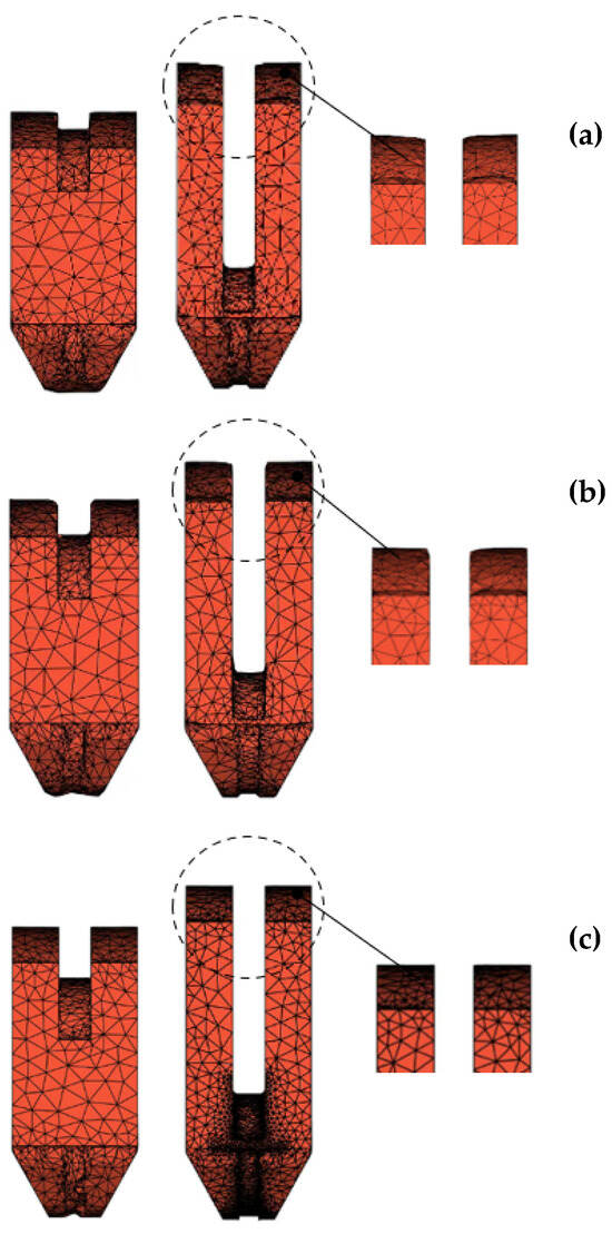
Figure 18.
Grooved and upset billet and final billet with different : (a) , (b) , (c) .
As discussed in Section 3.1.2, the initial billet before grooving–upsetting is not centered. This asymmetry leads to uneven web forming, and a very high load is required at the end of the process to complete the underfilled web (see Figure 7 and Figure 8). Similarly, the deeper the groove, the higher the load required at the grooving–upsetting step. It would be impractical to require an unreasonably high forging load just to maintain the web’s journal end shape. For this reason, it is necessary to study the influence of groove depth on the load. For convenience, a load coefficient (z) is introduced, expressed by Equation (6):
where, is the maximum load at the grooving–upsetting step when while , the maximum load when (i.e., the upsetting step in the U/BE).
Table 7 shows the calculated values of z for different combinations of k and χ. It can be seen that the load does not increase significantly, and the maximum value of z is 1.08. In fact, an appropriate increase in groove depth does not cause a significant change in the temperature, deformation zone, or outer surface area of the billet, and therefore, will not substantially increase the forging load.

Table 7.
Effect of the groove depth on load.
5. Experiment
The main purposes of a forging process are to achieve the part’s required shape and improve its properties [29]. Shape is the primary requirement; in addition, the performance of the forging should be enhanced as much as possible.
5.1. Near-Net Forged Crank Throw Experiment
An S90 crank throw weighs 19.7 tons, and its forging weighs 32.50 tons. Therefore, scaled-down experiments are commonly used for scientific investigations. In this study, a scale of 1:5 is selected for the experiment, and the initial billet weighs 260.4 kg.
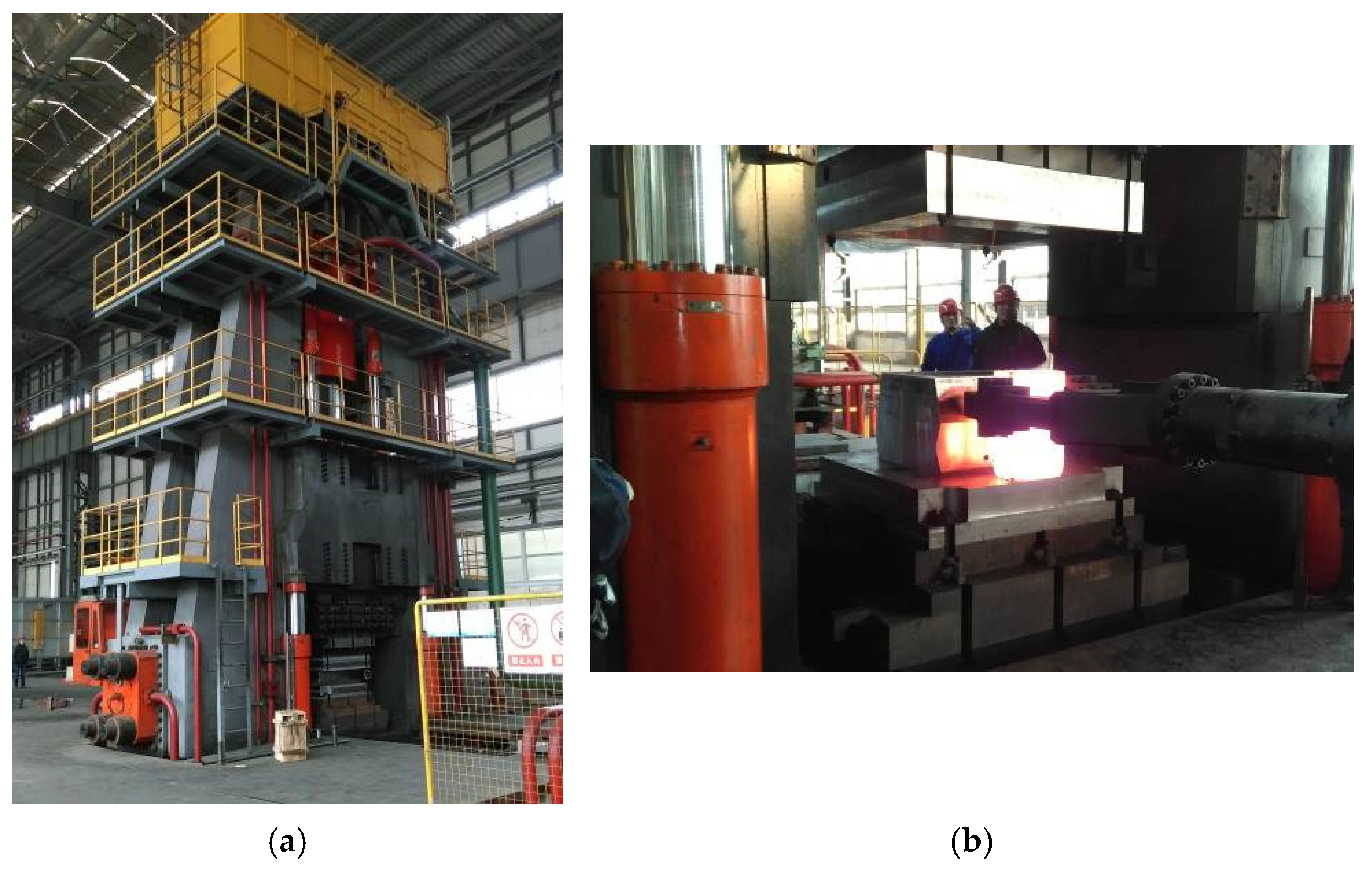
The press used in the experiments is a 12,000-ton press at the Precision Forging Company of China MCC22 Group Corporation Ltd. (Tangshan, China). Figure 19 shows the press and the tooling used in the experiments.
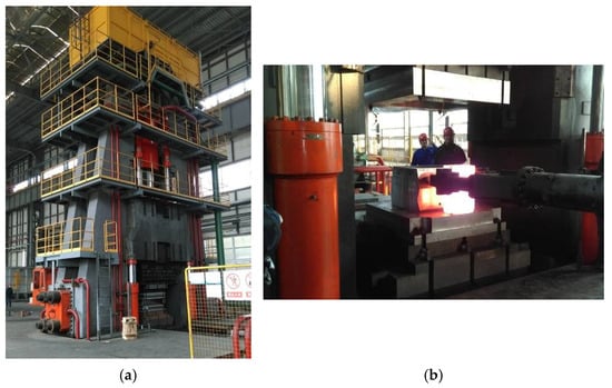
Figure 19.
(a) Press and (b) tools used for experiments.
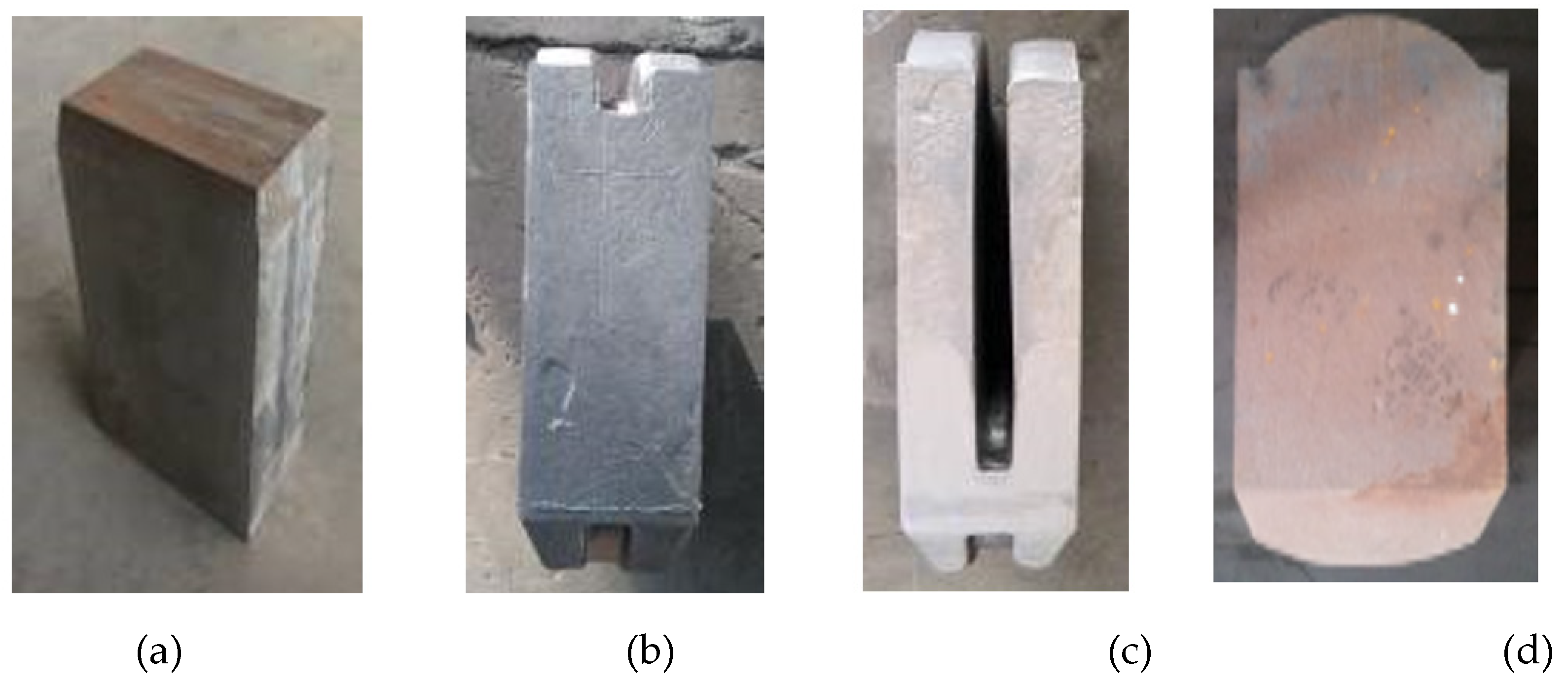
The procedure is as follows: billet cutting → heating → high-pressure water de-scaling → G–U/BE. Figure 20 shows the billet at different stages: (a) initial billet, (b) after grooving–upsetting, (c) and (d) as the final forging. It is clear that the near-net forged crank throw using grooving–upsetting/backward extrusion meets the required shape specifications.
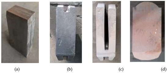
Figure 20.
Experiment of a near-net forged crank throw: (a) initial billet, (b) after grooving–upsetting, (c,d) as the final forging.
5.2. Microstructure and Performance Testing
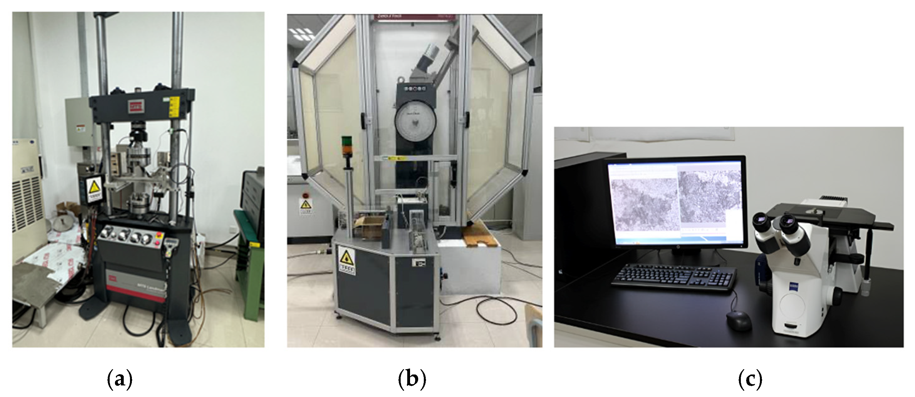
Crankshafts’ high-temperature and high-pressure working conditions impose extremely high requirements on the throws’ microstructure and mechanical properties [30]. Microstructure and property tests were carried out on a near-net forged crank throw according to the forged crank throw acceptance criteria [31]. Figure 21 shows the specimens for tensile and impact tests, as well as the microstructure analysis. The results are listed in Table 8 and Table 9. Figure 22 shows the equipment that was used for the various tests.

Figure 21.
Test specimens: (a) tensile test, and (b) impact test.

Table 8.
Test results for the mechanical properties (S34MnV steel).

Table 9.
Microstructure results (S34MnV steel).
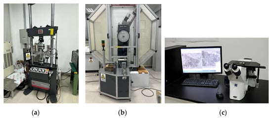
Figure 22.
Experimental equipment: (a) material fatigue testing system; (b) pendulum impact testing machine; (c) metallographic microscope.
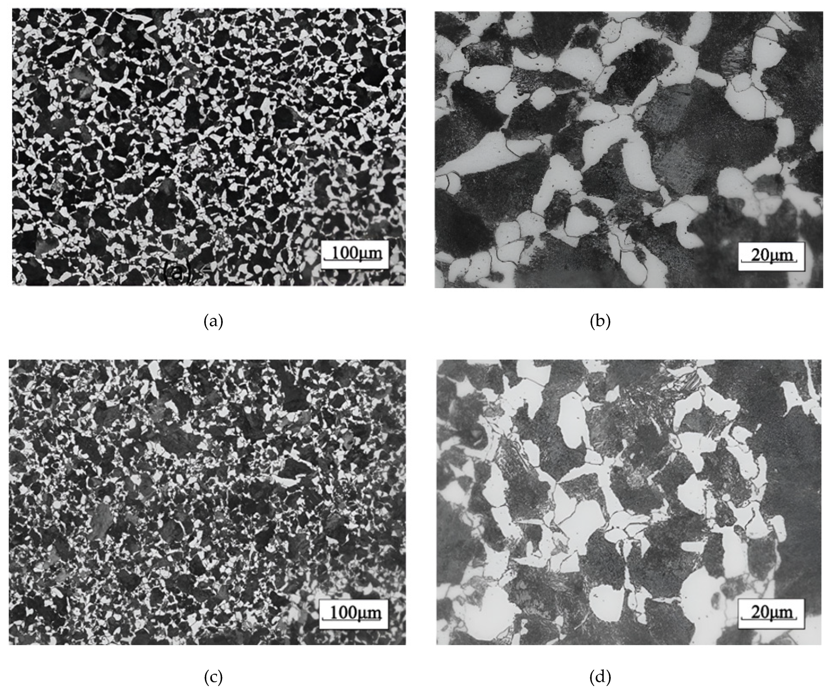
The ASTM grain size number, also referred to as G, was determined by measuring the average grain size using the intercept procedure outlined in the ASTM E112-13(2021) [32] standard. This method provides a precision better than ±0.25 grain size units. The macrostructure analysis was performed using the ZEISS Axio Imager (a light microscope for material sciences), as shown in Figure 22c, in conjunction with the ZEISS ZEN core analysis software and its GxP module for the intercept procedure.
Figure 23 shows that the forged crank throw obtained a homogeneous microstructure with a grain size number of 7. The test results indicate that all measured indexes are well above the required values.
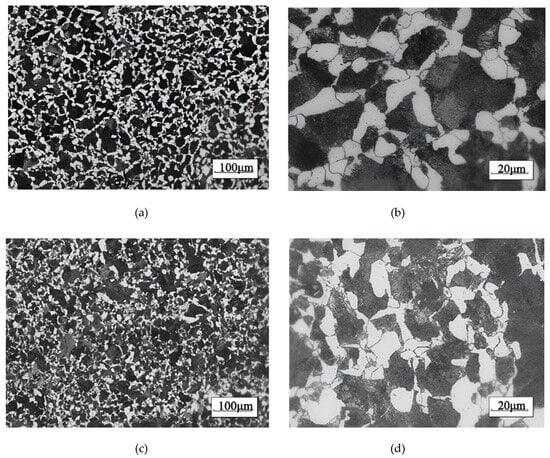
Figure 23.
Microstructures of forged throws: (a) specimen #1 100 µm scale, (b) specimen #1 20 µm scale, (c) specimen #2 100 µm scale, and (d) specimen #2 20 µm scale.
6. Conclusions
- Finite element (FE) software was used to simulate three near-net-shape (NNS) forming methods: OSE, U/BE, and G–U/BE. The results indicate that G–U/BE requires the lowest load.
- The journal end web shapes formed at the end of the grooving–upsetting step in the G–U/BE process create a rigid zone that remains intact during the subsequent backward extrusion. The relative groove depth (χ) significantly influences the final forging. Deeper grooves are more favorable for the final crank throw formation but require a higher load at the grooving–upsetting stage.
- When χ is greater than or equal to 1.5, the web’s journal end shape is optimal. However, if the groove depth exceeds this value, the required load increases to levels comparable to one-step extrusion, rendering the grooving–upsetting step ineffective. Therefore, the optimal value of χ is 1.5.
- Scaled-down experiment results confirm that G–U/BE is a practical and feasible NNS forming method for producing large marine crank throw forgings, achieving both the desired shape and microstructure.
Author Contributions
Conceptualization, L.N. and Q.Z.; methodology, L.N., Q.Z., J.W. and X.V.; software, Q.Z. and Y.Z.; validation, Y.Z., J.W., W.L., D.L. and T.M.; formal analysis, L.N. and W.L.; investigation, L.N., J.W. and W.L.; resources, L.N. and X.V.; data curation, Q.Z., D.L. and T.M.; writing—original draft preparation, L.N., Q.Z. and Y.Z.; writing—review and editing, X.V.; visualization, Q.Z., Y.Z., D.L. and T.M.; supervision, L.N. and X.V.; project administration, L.N. and X.V.; funding acquisition. All authors have read and agreed to the published version of the manuscript.
Funding
The authors wish to express their sincere gratitude for the support received from the Industry-University-Research Cooperation: Project of Jiangsu Province (Project No. BY20230258), the Shanghai Engineering Technology Research Center of Multi-directional Die Forging (Project No. 20DZ2253200), as well as the Key Scientific Research Platform and Projects of the Guangdong Provincial Department of Education (Project No. 2024ZDZX3065), which made this research project possible. The funding has not only provided the necessary resources but also fostered an environment conducive to innovative research and scholarly exploration.
Data Availability Statement
The original contributions presented in this study are included in the article Further inquiries can be directed to the corresponding author.
Conflicts of Interest
The authors declare no conflicts of interest.
References
- Gomes, J.; Gaivota, N.; Martins, R.F.; Silva, P.P. Failure analysis of crankshafts used in maritime V12 diesel engines. Eng. Fail. Anal. 2018, 92, 466–479. [Google Scholar] [CrossRef]
- Meier-Peter, H.; Bernhard, F. Compendium Marine Engineering; Seehafen Verlag: Hamburg, Germany, 2009. [Google Scholar]
- Kubo, H.; Mori, H. Trends in Manufacturing and Technological Development of Crankshaft Material. Mar. Eng. 2006, 41, 672–676. [Google Scholar] [CrossRef] [PubMed]
- Hanawa, Y.; Kajihara, S.; Kagawa, Y.; Mori, H.; Hamada, T. Development of High Strength Cast Steel for Semi-built up Type Crankshaft of Low Speed Diesel Engine, and Stress Measurement and Evaluation of Crankshaft. Mar. Eng. 2005, 40, 254–259. [Google Scholar] [CrossRef] [PubMed]
- Fonte, M.; Duarte, P.; Anes, V.; Freitas, M.; Reis, L. On the assessment of fatigue life of marine diesel engine crankshafts. Eng. Fail. Anal. 2015, 56, 51–57. [Google Scholar] [CrossRef]
- Instructions on the Group Standard of General Technical Specifications for Die Forging Marine Crankshaft Forgings. 2022, Confederation of Chinese Metalforming Industry. Available online: https://max.book118.com/html/2023/1222/5032211321011030.shtm (accessed on 25 December 2024). (In Chinese).
- Liu, K. Study on Die Forging Process of Large-Sized Crankthrow by Simulation; Yanshan University: Qinhuangdao, China, 2012. [Google Scholar]
- Song, M.C.; Lee, Y.U.; VanTyne, C.; Moon, Y.H. Symmetric bending technology using a floating die to forge crank throws for marine engines. J. Mater. Process. Technol. 2016, 237, 197–207. [Google Scholar] [CrossRef]
- Fujitsuna, N. Development of Steel Castings and Forgings for Vessels. Kobelco Technol. Rev. 2017, 35, 1–6. [Google Scholar]
- Altan, T.; Fiorentino, R.J. Prediction of Loads and Stresses in Closed-Die Forging. J. Eng. Ind. 1971, 93, 477–484. [Google Scholar] [CrossRef]
- Tanishq Jaiswal, V.I.; Kakde, A. A Review on closed die forging. Int. J. Adv. Eng. Manag. 2022, 4, 5. [Google Scholar]
- Sheth, D.; Das, S.; Chatterjee, A.; Bhattacharya, A. Modeling of Closed-Die Forging for Estimating Forging Load. J. Inst. Eng. Ser. C 2017, 98, 53–61. [Google Scholar] [CrossRef]
- Li, C.; Li, M.V.; Li, S.; Li, D.; Peng, X. Effect of stresses on martensite transformation kinetics and transformation plasticity of S34MnV steel. Mater. Res. Express 2019, 6, 076531. [Google Scholar] [CrossRef]
- Zhang, Z.; Li, H.; Zhou, Y.; Guo, W.; Jiang, R.; Zhu, Y. Research on Thermal Deformation Behavior of Marine Crankshaft S34MnV Steel. Steel Res. Int. 2021, 92, 2100140. [Google Scholar] [CrossRef]
- Yan, Y.; Li, M.V.; Bu, H.; Zheng, S. Continuous Cooling Transformation Behavior and Transformation Kinetics of S34MnV Steel. Cailiao Daobao/Mater. Rep. 2021, 35, 20129–20136. [Google Scholar] [CrossRef]
- Hu, Z.; Wang, K.; Yang, Y. A comparative study on the activation energy for hot deformation of 5CrNiMoV and S34MnV steel. Curr. Mater. Sci. 2021, 14, 70–79. [Google Scholar] [CrossRef]
- Chen, Z.; Nash, P. Hot Deformation Behavior and Processing Maps for a Large Marine Crankshaft S34MnV Steel. Steel Res. Int. 2018, 89, 1700321. [Google Scholar] [CrossRef]
- Hu, Z.; Wang, K.; Yang, Y. Modelling and simulation of a bending process for S34MnV steel. Int. J. Microstruct. Mater. Prop. 2019, 14, 432–447. [Google Scholar] [CrossRef]
- Chen, Z.; Nash, P.; Zhang, Y. Correlation of Cooling Rate, Microstructure and Hardness of S34MnV Steel. Metall. Mater. Trans. B 2019, 50, 1718–1728. [Google Scholar] [CrossRef]
- Jayanthi, A.; Anilkumar, M.; Ravisankar, B. Selection of forging process for compressor disc for aero engine using finite element analysis. Mater. Today Proc. 2022, 60, 2111–2116. [Google Scholar] [CrossRef]
- Raja, N.; Daniel, B.S.S. Microstructural and mechanical characteristics of hot worked homogenized AA7068 using 3D processing map and DEFORM-3D. Mater. Today Commun. 2023, 36, 106574. [Google Scholar] [CrossRef]
- Zeng, Y.; Ji, H.; Song, C.; Wang, M.; Li, J. Numerical simulation and experiment on hot forging of high-Mn steel turnout core. Mater. Today Commun. 2024, 40, 109588. [Google Scholar] [CrossRef]
- Zhang, L.; Lu, R.; Tang, J.; Jiang, F.; Fu, D.; Zhang, H.; Teng, J. Microstructural Evolution and Mechanical Properties of a Continuously Cast Al–Mg–Si–Cu Alloy Processed by Repetitive Continuous Extrusion Forming. Met. Mater. Int. 2023, 29, 2028–2039. [Google Scholar] [CrossRef]
- Xu, Z.; Wang, S.; Gao, L.; Qiao, X.; Cui, Y. Fatigue life analysis model of crankshaft under uncertain working conditions based on physical-data collaboration. J. Eng. Res. 2023, in press. [Google Scholar] [CrossRef]
- Derazkola, H.A.; Garcia, E.; Murillo-Marrodán, A.; Hardell, J. The effect of temperature and strain rate on the mechanical properties and microstructure of super Cr13 martensitic stainless steel. J. Mater. Res. Technol. 2023, 24, 3464–3476. [Google Scholar] [CrossRef]
- Derazkola, H.A.; García Gil, E.; Murillo-Marrodán, A.; Méresse, D. Review on dynamic recrystallization of martensitic stainless steels during hot deformation: Part I—Experimental Study. Metals 2021, 11, 572. [Google Scholar] [CrossRef]
- Momeni, A.; Dehghani, K. Prediction of dynamic recrystallization kinetics and grain size for 410 martensitic stainless steel during hot deformation. Met. Mater. Int. 2010, 16, 843–849. [Google Scholar] [CrossRef]
- Sakai, T.; Belyakov, A.; Kaibyshev, R.; Miura, H.; Jonas, J.J. Dynamic and post-dynamic recrystallization under hot, cold and severe plastic deformation conditions. Prog. Mater. Sci. 2014, 60, 130–207. [Google Scholar] [CrossRef]
- Chen, Z. Study on Numerical Simulation of Metal Flow and Microstructure Evolution of a Crankshaft Forging Process. 2013. Available online: https://xueshu.baidu.com/usercenter/paper/show?paperid=af5310c3647d0b4a20fb10c916c9fce2&site=xueshu_se (accessed on 25 December 2024).
- Taylor, D.A. Introduction to Marine Engineering; Elsevier: Amsterdam, The Netherlands, 1996. [Google Scholar]
- Society, C. Section 4 Forgings for Crankshafts. Available online: https://www.imorules.com/LRMAT_CH5_4.html (accessed on 28 November 2024).
- ASTM E112-13; Standard Test Methods for Determining Average Grain Size. ASTM International: West Conshohocken, PA, USA, 2021.
Disclaimer/Publisher’s Note: The statements, opinions and data contained in all publications are solely those of the individual author(s) and contributor(s) and not of MDPI and/or the editor(s). MDPI and/or the editor(s) disclaim responsibility for any injury to people or property resulting from any ideas, methods, instructions or products referred to in the content. |
© 2024 by the authors. Licensee MDPI, Basel, Switzerland. This article is an open access article distributed under the terms and conditions of the Creative Commons Attribution (CC BY) license (https://creativecommons.org/licenses/by/4.0/).

