Article

Effect of Aging Temperature on the Impact Wear Properties and Wear Mechanism of Lightweight Wear-Resistant Steel

1
State Key Laboratory of Metastable Materials Science and Technology, Yanshan University, Qinhuangdao 066004, China
2
Taiyuan Heavy Industry Co., Ltd., Taiyuan 030032, China
3
Hebei Key Lab for Optimizing Metal Product Technology and Performance, Yanshan University, Qinhuangdao 066004, China
*
Author to whom correspondence should be addressed.
Metals 2025, 15(2), 178; https://doi.org/10.3390/met15020178
Submission received: 25 October 2024 / Revised: 20 December 2024 / Accepted: 15 January 2025 / Published: 10 February 2025
(This article belongs to the Special Issue Metal Rolling and Heat Treatment Processing)

Abstract

:
In this study, the microstructure, mechanical properties, wear resistance, and wear-hardening mechanism of Fe-28Mn-8.5Al-1.0C lightweight wear-resistant steel after heat treatment at different aging temperatures were examined. The results show that the nano-scale κ-carbides precipitated in the grains after aging treatment increased the strength and hardness of the material through the strengthening effect of the second phase. The yield strength of the material is 697 MPa, the tensile strength is 905 MPa, and the hardness is up to 294 HB after aging at 500 °C for 5 h. However, the large-sized κ-carbides precipitating continuously at the grain boundary are unfavorable to the plasticity and toughness of the material. Compared with the aging treatment at 300 °C for 5 h, the elongation and low-temperature impact energy decreased by 12.0% and 47.1%, respectively. Except for the dominant wear mechanism being plastic deformation after heat treatment at 500 °C for 5 h with a 4J impact energy, the predominant wear mechanisms for different impact energies under all other heat treatment conditions are micro-cutting. The increase in aging temperature increases the number and volume of κ-carbide precipitation, which leads to enhanced second-phase strengthening and dislocation strengthening, and the wear resistance of the material is improved. The hardening mechanism of the material after wear at different impact energy levels under aging treatment conditions is a cross-distributed dislocation wall and high-density dislocation entanglement. The increase in aging temperature reduces the spacing of the dislocation wall, increases the area and density of dislocation entanglement, and enhances the work-hardening effect.

1. Introduction

Hadfield steel is widely used in mining machinery, such as ore crushers, due to its excellent wear resistance [1,2]. However, with the development of metallurgy, machinery manufacturing, and other related industries, industrial equipment requirements are also increasing; the used workpieces weigh from a few tons to hundreds of tons, which inevitably leads to a sharp increase in the power consumption of equipment. Although Hadfield steel has a strong work-hardening ability and a certain toughness under abrasive wear conditions, its initial hardness and yield strength are low [3]. This also limits the environment in which it can be used. That is, the work-hardening capacity can only be fully utilized under high stress or high-impact loads [4,5,6,7]. At present, wear-resistant high-manganese steel materials are developing toward a higher manganese content and alloying. For example, Lu et al. [8] compared cast steel Mn18Cr2 with Mn13Cr2, and found that Mn18Cr2 has a higher wear and work-hardening ability and a more ideal combination of high hardness and impact toughness. Yan et al. [9] studied Mn13CrMo steel and found that, after alloying, its yield strength and wear resistance were 1.38 times and 1.35 times that of ordinary high manganese steel, respectively. However, the problem of high energy consumption due to traditional high-manganese steel workpieces has still not been solved effectively.
In recent years, domestic and foreign scholars have increasingly conducted in-depth research on Fe-Mn-Al-C lightweight high-manganese steel and Fe-Mn-Al-C lightweight high-strength steel, adding a certain amount of Al to the basic component of high-manganese steel in order to reduce the material’s density and weight. With a 1% increase in aluminum content, the density of Fe-Mn-Al-C light high-manganese steel was reduced by about 1.3%, when compared with traditional high-manganese steel [10]. As a new material with low cost, low density, high strength, and high plastic toughness, it has excellent mechanical properties: the yield strength can reach 1000 MPa, the tensile strength can reach 2000 MPa, and the elongation can reach 100% [11].
Researchers at home and abroad have studied the mechanical properties and strengthening mechanism of Fe-Mn-Al-C lightweight high-strength steel. The results reported in [12,13,14,15] show that, after proper heat treatment (aging treatment) of Fe-Mn-Al-C steel, fine-sized carbides precipitate in the crystal of the material, which hinder the movement of dislocation during the deformation process of the material and thus improve its comprehensive strength. Peng Shiguang et al. [16] studied the impact wear performance of Fe-24Mn-7Al-1.0C steel in the aged state, and found that the wear resistance of Fe-Mn-Al-C high-strength steel was 1.40 times that of Mn13Cr2 steel after solution treatment at a low impact energy of 0.5 J. BA et al. [17] studied the impact wear properties of Fe-25Mn-7Al-1.0C steel, and found that the wear resistance of the material after explosion-hardening after aging treatment was 1.61~1.68 times that of Mn13Cr2 steel. Zheng et al. [18] studied the work-hardening mechanism of light high-manganese steels with different Al contents and showed that, without Al, the work-hardening mechanism of Fe-18Mn-1.3C-2Cr steel was twinned and dislocation cells. When the Al content was 4 and 7 wt %, a deformation zone and plane dislocation slip were observed, respectively. When the content of Al was 11 wt %, the precipitation of kappa carbide promoted work-hardening. However, the comprehensive control mechanism of the microstructure, mechanical properties, and impact wear resistance of light high-manganese steel under different aging temperatures and impact stress conditions is still unclear. Therefore, this study combined solution technology and aging treatment to research the self-developed 28Mn-8.5Al-1.0C light wear-resistant steel, systematically discussing the effects of different aging temperatures on the microstructure, mechanical properties, impact wear properties, and work-hardening mechanism of light wear-resistant steel. This was performed in order to further explore the potential of Fe-Mn-Al-C light austenitic high-manganese steel to replace traditional wear-resistant high-manganese steel and provide a solid theoretical basis for further research and development of this material.

2. Experimental Materials and Methods

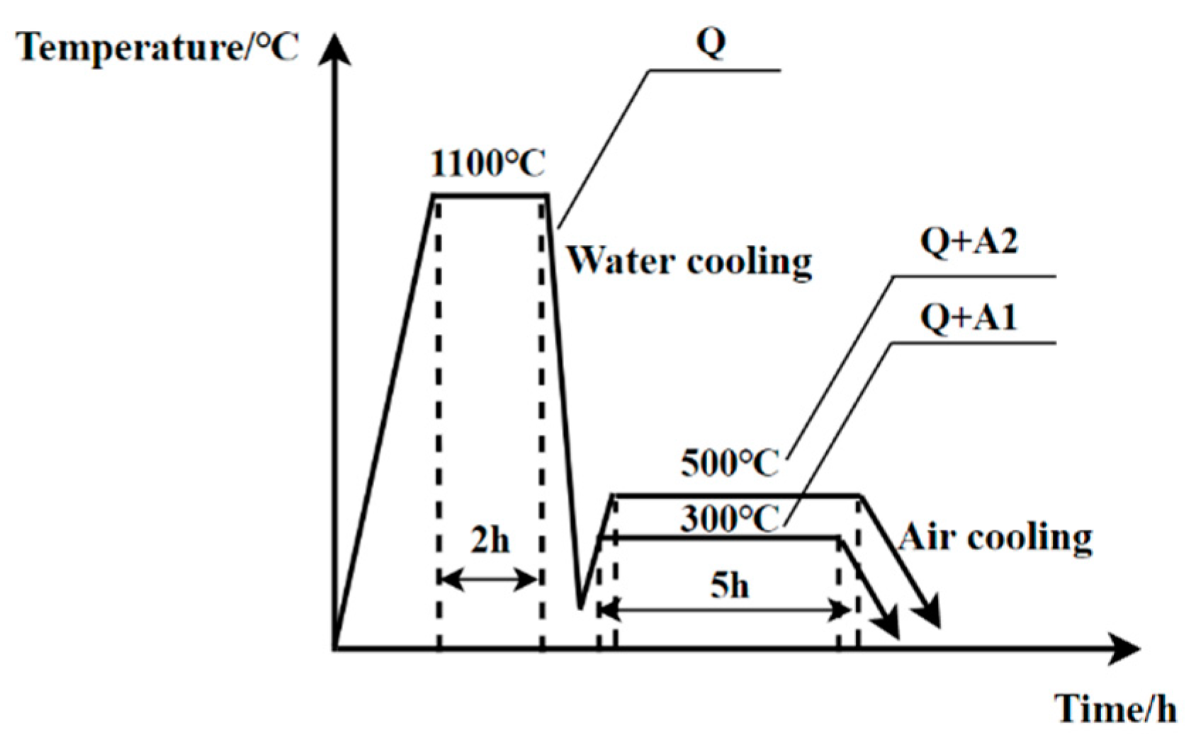
2.1. Raw Material Processing and Heat Treatment Technology

In this study, Fe-28Mn-8.5Al-1.0C light wear-resistant steel material was taken as the research object, and the chemical composition of the material is shown in Table 1. The original ingot (100 kg), obtained after smelting and cooling with a 200 kg vacuum induction melting furnace, was cut using a sawing machine and EDM into blank specimens of impact, tensile, and impact wear, respectively. The blank size of the impact specimen was 13 mm×13 mm×60 mm, the blank size of the tensile specimen was 13 mm × 13 mm × 90 mm, and the blank size of the impact wear sample was 13 mm × 13 mm × 35 mm.
In order to obtain a single and stable structure, eliminate the non-uniformity of the as-cast structure of the material, and explore the effect of the aging temperature on the microstructure and comprehensive properties of light wear-resistant steel, the light wear-resistant steel was heat-treated with the following processes: (1) 1100 °C holding heat for 2 h solution treatment; (2) 1100 °C holding for 2 h solution treatment +300 °C holding for 5 h aging treatment; and (3) 2 h solution treatment at 1100 °C + 5 h aging treatment at 500 °C. The heat treatment process curve is shown in Figure 1. In order to facilitate the description below, the heat treatment process of Fe-28Mn-8.5Al-1.0C steel was defined as Q and Q + A1/A2, respectively.
The raw blank was refined into the tensile test specimen with a cross-section diameter of 10 mm and the original standard distance of 50 mm using the milling machine. V-notch samples had a size of 10 mm × 10 mm × 55 mm. For impact wear test specimens with a size of 10 mm × 10 mm × 30 mm, the mechanical properties of each group under different heat treatment processes were tested three times, and the average value of the data was taken as the experimental result. The hardness test sample is the sample after impact wear, 5 data points were tested at equal spacing on the wear surface, and the average value was taken as the result.

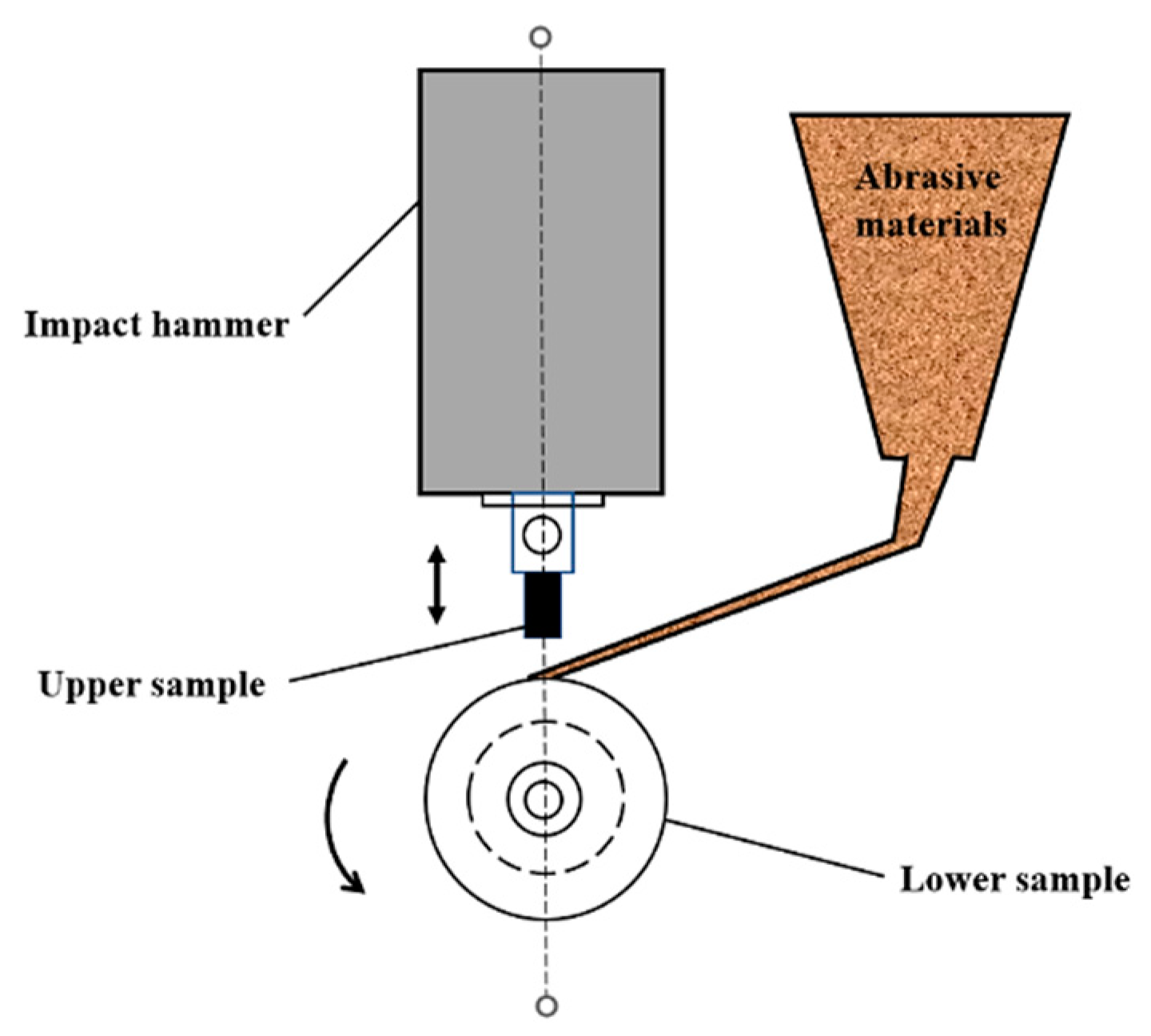
2.2. Impact Abrasive Wear Test

The MLD-10B dynamic load abrasive wear testing machine was used to test the wear resistance of the material, and 1 J and 4 J of impact energy were selected for the material experiment. The structural principle of the testing machine is shown in Figure 2. The upper sample is the standard sample (test material), driven by a 10 kg punching hammer to perform the cyclic up and down movement at the impact frequency of 200 times/min. The lower sample is a circular counter-grinding sample; the outer circle’s diameter is φ50 mm; the inner circle’s diameter is φ30 mm; and the thickness is 15 mm, driven by the motor spindle at the speed of 200 r/min, performing rotary reciprocating counter-grinding. Among them, the lower sample (grinding sample) is tempered 45 steel (0.44%C, hardness 58HRC). The abrasive is made of special quartz sand with a diameter of 1.5~2.36 mm, and the abrasive flow rate is 20 kg/h. The test time of each sample was 1 h, and three experiments were conducted under each impact energy. After the experiment was completed, acetone solution and anhydrous ethanol solution were used to clean the material in the ultrasonic cleaning instrument for 180 s, respectively. The electronic balance with 0.1 mg accuracy was used to weigh each sample three times, and the average value of the weighing data was taken as the wear result.

2.3. Analysis Method

The surface of the sample polished before and after wear was corroded with 20% nitrate alcohol solution, and the microstructure of the experimental material was observed using Axiover-200MAT Zeiss metalloscopy (Zeiss, Oberkochen, Germany). A Rigaku D/max-2500/PC X-ray diffractometer (Cu target) (Bruker, Billerica, MA, USA) was used to analyze the phase composition of the samples before and after heat treatment. The operating voltage was 40 kV, and the current was 100 mA. The raised part of the worn sample was cut off, and the Brinell hardness test was conducted on the worn surface after polishing. The surface microstructure of worn samples was observed using an S3400N scanning electron microscope (Hitachi, Tokyo, Japan) equipped with an ESL electron backscatter diffraction (EBSD) probe. The sample with a thickness of 200 μm was cut using an electric discharge wire, sanded to a thickness of 30 μm, and then subjected to 90 vol.% anhydrous ethanol and 10 vol.% perchloric acid solution at −20 to −40 °C to prepare the thin slice sample for transmission electron microscope (TEM) observation. The substructures of typical sample materials with different heat treatment processes were observed using a (TEM) JEOL 2010 (JEOL, Tokyo, Japan).

3. Results and Discussion

3.1. Microstructure and Mechanical Properties

The optical microscopy (OM) morphology of Fe-28Mn-8.5Al-1.0C steel under different heat treatment conditions is shown in Figure 3a–c. OM images show that the microstructure matrix of Fe-28Mn-8.5Al-1.0C steel under the three heat treatment processes is austenite. After aging treatment, different sizes of second-phase precipitation are observed in austenite grains and between grain boundaries. With the increase in the aging temperature, the size of granular second-phase precipitation increases. The area ratio of the second-phase precipitation in Q + A1 and Q + A2 processes is about 1.02% and 1.83%, respectively. It can be seen that the amount of second-phase precipitation increases with the increase in the aging temperature. OM images show the average grain size of Fe-28Mn-8.5Al-1.0C steel under the conditions of Q, Q + A1, and Q + A2 is 1016 ± 382 μm, 943 ± 352 μm, and 934 ± 378 μm, respectively. With an increase in aging temperature, the grain size of the material changes little. This is similar to the findings of other scholars [19,20]. According to the Hall–Petch theory, the relationship between the influence of fine-grain strengthening on the material is as follows:
σ y = σ 0 + k H P d 0 . 5
where my is the yield strength (MPa), and σ0 is other strengthening factors (MPa) except for fine-grain strengthening. kHP is the influence factor of grain boundary strengthening, namely, the Hall–Petch slope (MPa·μm0.5), and d is the grain size (μm). According to the data, the kHP value of the Hall–Petch slope is 365 MPa·μm0.5 [21], and only the influence of fine-grain strengthening is considered here, so the influence formula of fine-grain strengthening is as follows:
σ y = k H P d 0 . 5
It was calculated that the contribution of fine-grain strengthening to the yield strength under Q, Q + A1, and Q + A2 processes is 11 MPa, 12 MPa, and 12 MPa, respectively. It can be seen that fine-grain strengthening has little effect on the yield strength of the material.
As OM images could not be used to determine the type of second-phase precipitation and other information, X-ray diffraction analysis was conducted on Fe-28Mn-8.5Al-1.0C steel under different heat treatment processes, and the XRD pattern is shown in Figure 4. No phase transition was observed under the three heat treatment conditions, similar to the results found by Shin et al. [22]. The diffraction peak that can be observed in the pattern of Q and Q + A1 processes is the γ phase; that is, the phase composition inside the material analyzed according to the XRD pattern is a single austenite. When the aging process is held at 500 °C for 5 h (Q + A2), the diffraction peak of κ (110) appears in the XRD pattern at the diffraction angle of 33°, and the second phase is precipitated into (Fe, Mn)3AlC κ-carbide [23,24,25,26,27]. The local magnification image shows that, compared with the Q process, the position of the γ(111) diffraction peak is shifted to the right, and the degree of deviation of the diffraction peak is increased when the aging temperature is further increased to 500 °C (Q + A2), which is related to the appearance of the second-phase precipitation dominated by κ-carbide. The saturated austenitic steel rich in Al, Mn, and C elements has an amplitude-modulating decomposition in the aging process, and the Al and C atoms are arranged in an orderly manner, which results in the transformation of M3C carbides into κ-carbides [14]. At the same time, the solid solubility of the austenite matrix decreases, and the lattice constant of the γ phase decreases. According to the Bragg equation, the lattice spacing d is inversely proportional to the diffraction angle θ, so the position of the γ-phase diffraction peak shifts to the right, supporting the results of the statistical analysis observed in the OM images above.
Figure 5 shows TEM and selected electron diffraction pattern (SAED) images of Fe-28Mn-8.5Al-1.0C steel after heat treatment using different processes. After solid solution treatment (Q), no second-phase precipitation was observed in the dark field image (DF) of the matrix inside the material, and the (SAED) determined that the structure was single-phase austenite (Figure 5a,b). After heat preservation at 300 °C for 5 h aging treatment (Q + A1) DF, as shown in the image, nano-sized granular point-like precipitates distributed in the matrix within a certain range were identified as κ-carbide by SAED (Figure 5c,d), whose structure is L’12 [14,28]. The average area accounted for about 4.64%, according to software analysis. When the aging temperature was further increased to 500 °C (Q + A2), the macroscopic quantity and volume of precipitates increased, and some forms were approximately distributed in the austenite matrix as chunks (Figure 5e,f). The average area proportion of κ-carbide was about 7.91%.
With the increase in aging temperature, the volume and quantity of κ-carbide increase, which is consistent with the above experimental results. At the same time, in the Q + A2 process, the average diameter of about 86 ± 15 nm was observed in the internal grain boundary of the material, and the continuous distribution of κ-carbides was observed in bulk (Figure 5g,h). This also indicates that κ-carbides grow in the matrix grain and grow in the grain boundary at the same time during heterogeneous phase precipitation [27]. The experimental results and related data show that there is a certain orientation relationship between austenite and κ-carbide, <100>κ//<100>γ and {010}κ//{010}γ [29,30]. The influence of κ-carbide on the comprehensive properties of materials is very important, and the influence of κ-carbide precipitated at different locations on the properties is also different [31,32,33].
The mechanical properties of Fe-28Mn-8.5Al-1.0C steel under different heat treatment conditions are shown in Table 2, and the gradient curves of the yield strength, tensile strength, and elongation after fracture are shown in Figure 6.
After the aging treatment, the strength and hardness of the material increased compared with the solution treatment, and the elongation and impact energy decreased at −40 °C. With an increase in aging temperature, the performance of the material under the Q + A2 process is 29.8% higher than that under Q + A1 process, the yield strength is increased by 5.1%, the elongation after breaking is decreased by 12.0%, the impact energy at −40 °C is decreased by 47.1%, and the hardness is increased by 6.5%; that is, the strength and hardness of the material are increased, and the plastic toughness is decreased. According to the above calculation, the effect of fine-grain strengthening on the yield strength of the material is small. Based on the analysis of the experimental observation phenomenon, the dispersion precipitation of nanoscale κ-carbide is an important factor leading to the abovementioned law of material properties. The second phase in Fe-Mn-Al-C system steel is strengthened in two ways: One is the effect of intragranular dispersion on dislocation motion during plastic deformation [34]. The other is strengthening the material through the grain boundary hard phase and thus hindering the co-deformation between grains [35]. Since most of the nanoscale κ-carbides observed in the above microscopic characterization are precipitated in the crystal, only the effect of intracrystalline dispersion on the properties is considered here, and the relationship is as follows [36,37]:
σ ph = M N γ APB b V 12 γ APB r π Gb 2 V
where σph is the second-phase strengthening (MPa), M is the Taylor factor, N is the number of intracrystalline κ-carbide accumulation dislocations, b is the Burger vector (nm), G is the γ shear modulus (GPa), V is the volume fraction (%) of κ-carbide in the crystal, r is the intracrystalline precipitation phase size (nm), and γAPB is the antiphase domain interface energy (mJ/m2). According to the calculation method for the average size of carbides in the reference data, [38] the average size of kappa carbides under two aging process conditions is approximately 1.7 ± 0.4 nm and 3.2 ± 0.3 nm, respectively. The value of γAPB varies from 0–20 at.% according to the C content, with a value of 350–650 mJ/m2, and the number of intracrystalline κ-carbide accumulation dislocations N is about 6–10 [39]. The value of M is 3.06, the value of b is 0.26 nm, and the value of shear modulus G is 70 GPa [40]. The second-phase strengthening contribution under the two aging conditions is 43 MPa and 61 MPa, respectively. The second-phase strengthening generated by the precipitation of nanoscale κ-carbide in the crystal is the main reason for the increase in strength and hardness of Fe-28Mn-8.5Al-1.0C steel after aging treatment. At the same time, the increase in aging temperature also increases the precipitation power of κ-carbide, and its quantity and size increase, further enhancing the second-phase strengthening effect.
The dispersed distribution of k-carbides within the grain has obvious directionality, and their growth also forms a secondary ordering along specific directions. This type of k-carbide can promote the improvement of material properties [41]. However, studies have shown that the continuous growth and distribution of k-carbides at grain boundaries can easily become the main source of cracks during deformation [42]. Combined with the observed k-carbides precipitated at grain boundaries in Figure 5g, their size is significantly larger than the dispersed small k-carbides inside the grains. The continuous precipitation of these k-carbides at grain boundaries enhances the sensitivity of grain boundaries to crack formation, weakens the bonding strength between grain boundaries and the matrix, and provides more favorable conditions for crack propagation, further affecting the plasticity and toughness of materials. This is the main reason for the decrease in post-fracture elongation and low-temperature impact energy of materials after aging treatment and aging temperature increase.

3.2. Impact Wear Resistance

In this study, the impact wear resistance of Fe-28Mn-8.5Al-1.0C material is calculated using the following formula [43]:
ε = 1 W
where ε is the wear resistance (g − 1)—that is, the reciprocal of the wear rate of the material per unit time—and W is the amount of wear (g/h) produced by wear of the material in unit time. The wear resistance of Fe-28Mn-8.5Al-1.0C steel under different heat treatment processes is shown in Table 3 and Figure 7.
The wear resistance of the material after heat treatment by three processes increases with the increase in impact energy, and the wear resistance is the highest under 4 J of impact energy. Under the same impact work, the wear resistance of the materials after aging treatment is higher than that in the solid solution state, and the wear resistance also shows an increasing trend with the increase in aging temperature. As mentioned above, after aging treatment and the increase in aging temperature, the hardness of the material matrix is further enhanced, which also has a similar rule in Table 3. After wearing under the same impact work, the surface hardness of the material increases with the increase in the aging temperature.
Compared with solid solution treatment under 1 J of impact work, the wear resistance of the two aging treatment conditions increased by 5.5% and 15.7%, respectively. Compared with solid solution treatment under 4 J of impact work, the wear resistance is improved by 9.4% and 21.3%, respectively, and the impact wear resistance reaches its best after the process of 500 °C, holding heat for 5 h (Q + A2) of aging. Relevant studies have shown [16,44] that hardness and strength are important factors determining the wear resistance of materials. After aging treatment and increasing the aging temperature, the κ-carbide precipitated in the grain strengthens the matrix of the material. The increase in the initial surface hardness is conducive to resisting abrasive wear, which gives the material good wear resistance under low-impact work (1 J).
At the same time, due to the effect of vertical impact stress, the subsurface of the material is stressed during the deformation process. Internal substructures also come into play. Austenitic light high-manganese steel has rapid work-hardening under high-impact loads [45], and a large number of deformed substructures are generated in the matrix. The precipitation of carbide acts as a hard projection to resist wear. At the same time, the movement of the dislocation of κ-carbide milled in the crystal and the grain boundary also plays a hindering role. However, dislocation strengthening is an important way of work-hardening austenitic high-manganese steel [46,47], which is significantly related to the improvement in the impact wear resistance of the material.
Figure 8 shows the kernel average misorientation (KAM) diagram of the worn edge of Fe-28Mn-8.5Al-1.0C material after aging treatment through different levels of impact work. With the increase in impact work, the average KAM value increases. Under the same impact work condition, the aging temperature increases, and the corresponding KAM value of the worn edge increases. After 4 J of impact work wear, the average KAM value reaches a peak value of 1.15° (Figure 8h), and the degree of plastic deformation is the largest.
The stress is relatively concentrated at the grain boundary, which indicates that the grain boundary has a strong hindering effect on the dislocation movement. Plastic deformation tends to occur preferentially at the grain boundary, and intragrain cooperative deformation gives excellent plastic deformation ability under high impact and improves impact wear resistance. The increase in the aging temperature increases the amount of second-phase kappa carbide precipitation at grain boundaries and in grains, which further impedes the movement of dislocation and further strengthens the work-hardening effect, which is reflected in the increase in local stress at grain boundaries and in grains. The experimental results show that the precipitation of kappa carbide at the grain boundary reduces the binding force between the grain boundaries to a certain extent, which reduces the impact toughness at low temperatures but has a favorable effect on the impact wear resistance of the material, which is due to the strengthening of the matrix and the hindering of the dislocation movement of the grain boundary napping.

3.3. Impact Wear Mechanism

Figure 9 is the SEM image of the wear surface of Fe-28Mn-8.5Al-1.0C steel after heat treatment via different processes.
For ease of comparison and understanding, Figure 10 shows a schematic diagram of the SEM morphology of the wear surface. After solid-solution treatment (Q), the wear surface morphology of the material after different impact work is dominated by a large area of furrowed trenches (Figure 9 and Figure 10a,b), accompanied by a few spalling pits and stratified pits generated by plastic deformation. Under 1 J of impact work, there are chiseling pits on the wear surface of the material, indicating that the hardening degree of the material surface under this impact work is not high. A large area of wear defects is produced, and further weight loss is achieved. Under 4 J of impact work, the wear surface is not much different from that of 1 J, and no chiseling pits are found, indicating that the increase in impact work improves the material surface’s work-hardening degree, thus having a good wear-resistant effect.
After the two aging treatments, the furrow morphology of the wear surface was reduced compared with that of the solution treatment (Figure 9 and Figure 10c–f), as well as the length. There were still a few spalling pits due to fatigue wear and stratified pits with high plastic deformation. The reduction in furrow also indicates that the strength and hardness of the matrix after aging treatment enhance the abrasive cutting resistance of the material, thus reducing the generation of abrasive chips and improving the wear resistance. Under 4 J of impact work, the furrow morphology on the wear surface of the material after the Q + A2 process is reduced and shorter than that of the Q + A1 process. Most of the wear morphology is dominated by plastic deformation marks—that is, another furrow shape formed on the surface of the abrasive cutting and extrusion material—and there are a few smaller spalling pits and stratified pits (Figure 9 and Figure 10f). This further proves that the increase in aging temperature increases the surface-hardening effect of the material, resulting in fewer wear defects and better wear resistance. The formation of the furrow crease is due to the fact that when abrasive particles cut the material’s surface, the surface matrix is pushed to the front and both sides of the furrow, but no cutting action is generated, and primary chips are formed. Such furrow topography is called a furrow crease [48]. In addition to the 4 J impact wear mechanism of the Q + A2 process, plastic deformation wear is the main wear mechanism, and micro-cutting is the auxiliary. The surface wear mechanism of Fe-28Mn-8.5Al-1.0C material after heat treatment of three processes is mainly cutting furlough; fatigue spalling is the auxiliary.

3.4. Work-Hardening Mechanism

Figure 11 shows the TEM morphology of the wear subsurface of Fe-28Mn-8.5Al-1.0C material after heat treatment at different aging temperatures.
Figure 11a,b shows that there are staggered dislocation walls and relatively scattered dislocations on the wear subsurface under 1 J of impact work. When the impact energy is increased to 4 J, the number and width of dislocation walls increase, with an average distance of 400~600 nm, and high-density dislocation entanglement (HDDT) appears in some areas. When the aging temperature was increased to 500 °C (Q + A2), the subsurface morphology of the material under 1 J of impact energy did not change much compared with that of Q + A1 (Figure 11c), showing a typical dislocation wall morphology. However, the restriction effect on dislocation movement was stronger, the dislocation density in the wall was higher, and the width of the dislocation wall was also larger. The subsurface topography of 4 J of impact energy shows a large-area high-density dislocation wall (HDDW) and dislocation entanglement (Figure 11d). The average distance of the dislocation wall is about 200~300 nm. SAED image calibration in some high-density dislocation entanglement shows that the structure is composed of austenite + κ-carbide. At the same time, the proportion of dislocation entanglement under the Q + A2 process is higher, which indicates that the increase in aging temperature under the same impact work condition leads to a higher dislocation density and a smaller dislocation movement distance on the subsurface of the material. Moreover, κ-carbide has a significant effect on the dislocation density [49,50].
Combined with the phenomenon mentioned above, the precipitation of nanoscale κ- carbide is the main reason for the dislocation morphology on the subsurface of the experimental material. In the process of impact wear, many dislocations are generated inside the material, and the critical energy required for the dislocation movement increases due to the precipitation of κ-carbide; that is, the dislocation movement needs to overcome the increased energy difference due to the appearance of κ-carbide, causing significant dislocation aggregation and distribution and leading to the work-hardening of the material. The increase in aging temperature increases the quantity and volume of nano-sized κ-carbide, further enhancing its hindering effect on dislocation movement, work-hardening effect, and thus higher wear resistance, which is also reflected in the wear surface hardness value in Table 3. However, the increase in the strength and initial hardness of the matrix due to the second-phase strengthening of kappa carbide mentioned above is also the reason for the increase in wear resistance. The dislocation strengthening and the second-phase strengthening jointly dominate the wear resistance of the experimental material. Mechanical twins and dislocation cells were not observed on the subsurface of the two aging processes, and the dislocation cells formed a microscopic structure with a three-dimensional spatial structure due to the increase in dislocation density [51,52]. This indicates that the subsurface of Fe-28Mn-8.5Al-1.0C material after aging treatment shows plane slip characteristics after impact wear, which is similar to the relevant conclusions of Peng [46] and Tang [53]. In summary, the work-hardening mechanism of Fe-28Mn-8.5Al-1.0C material after aging treatment at different temperatures is a dislocation wall under 1 J of impact work, and the work-hardening mechanism under 4 J of impact work involves high-density dislocation entanglement and a dislocation wall.

4. Conclusions

In order to explore the effects of different aging treatments and temperatures on the microstructure, mechanical properties, impact abrasive wear resistance, and wear work-hardening mechanism of Fe-28Mn-8.5Al-1.0C material, thus providing references for subsequent theoretical research and practical engineering applications in related aspects, the following conclusions were reached through experiments and analysis:
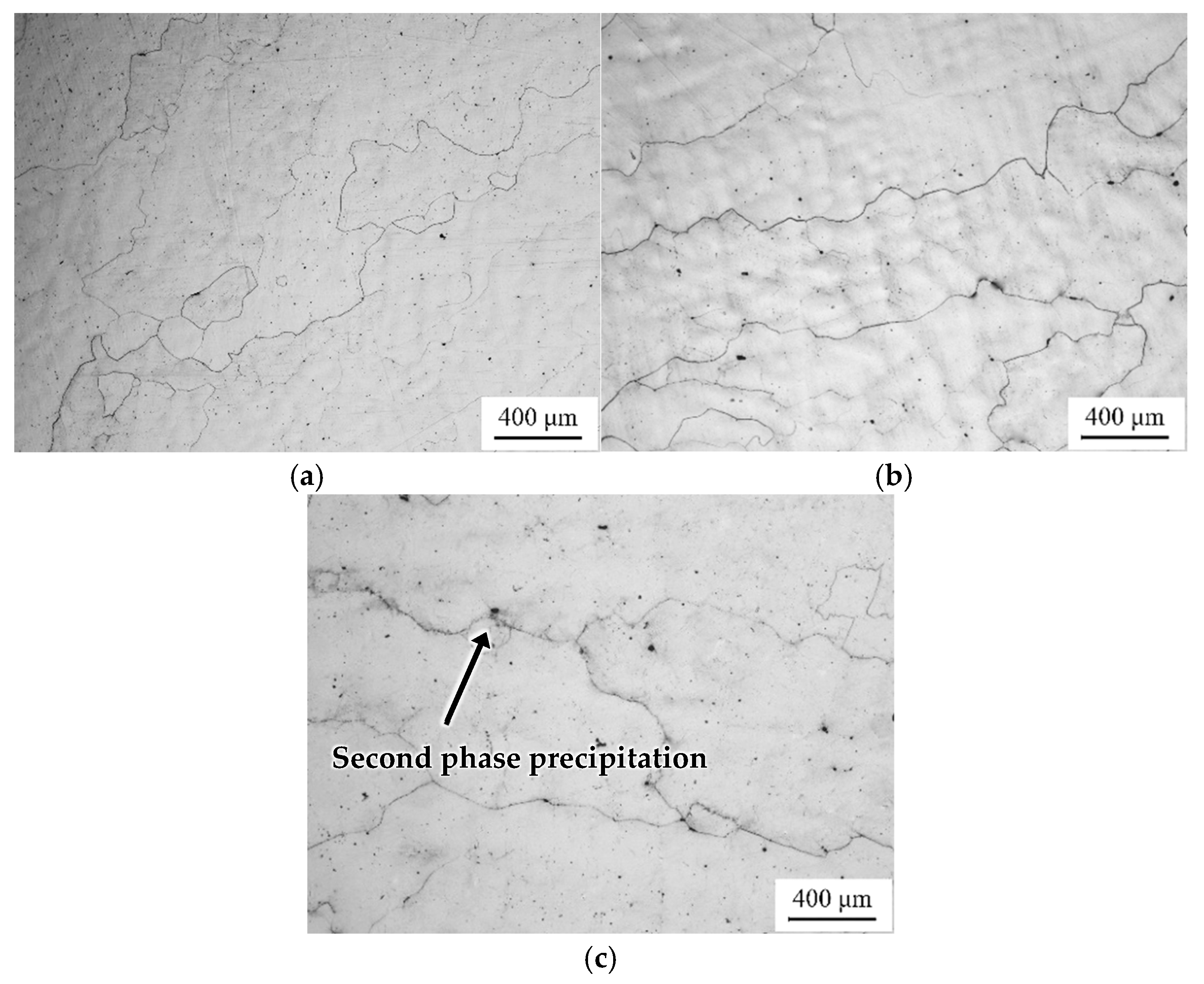
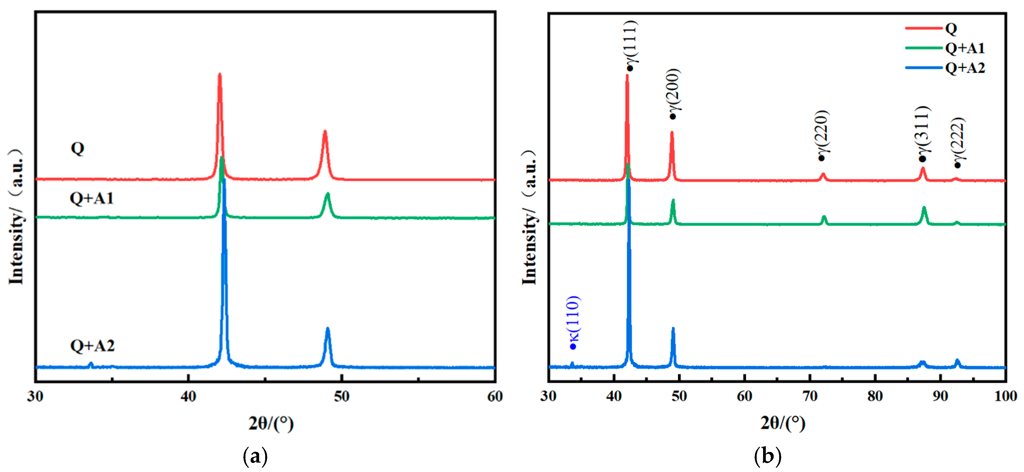
  • After solution treatment (Q) at 1100 °C and heat treatment at different aging temperatures, the matrix structure of Fe-28Mn-8.5Al-1.0C steel is austenite. After aging treatment, nanoscale κ-carbide is precipitated in the crystal and at the grain boundary. With an increase in aging temperature, the quantity and size of κ-carbide increase. After aging treatment (Q + A2) at 500 °C for 5 h, the average area ratio of κ-carbide can reach 1.83%.
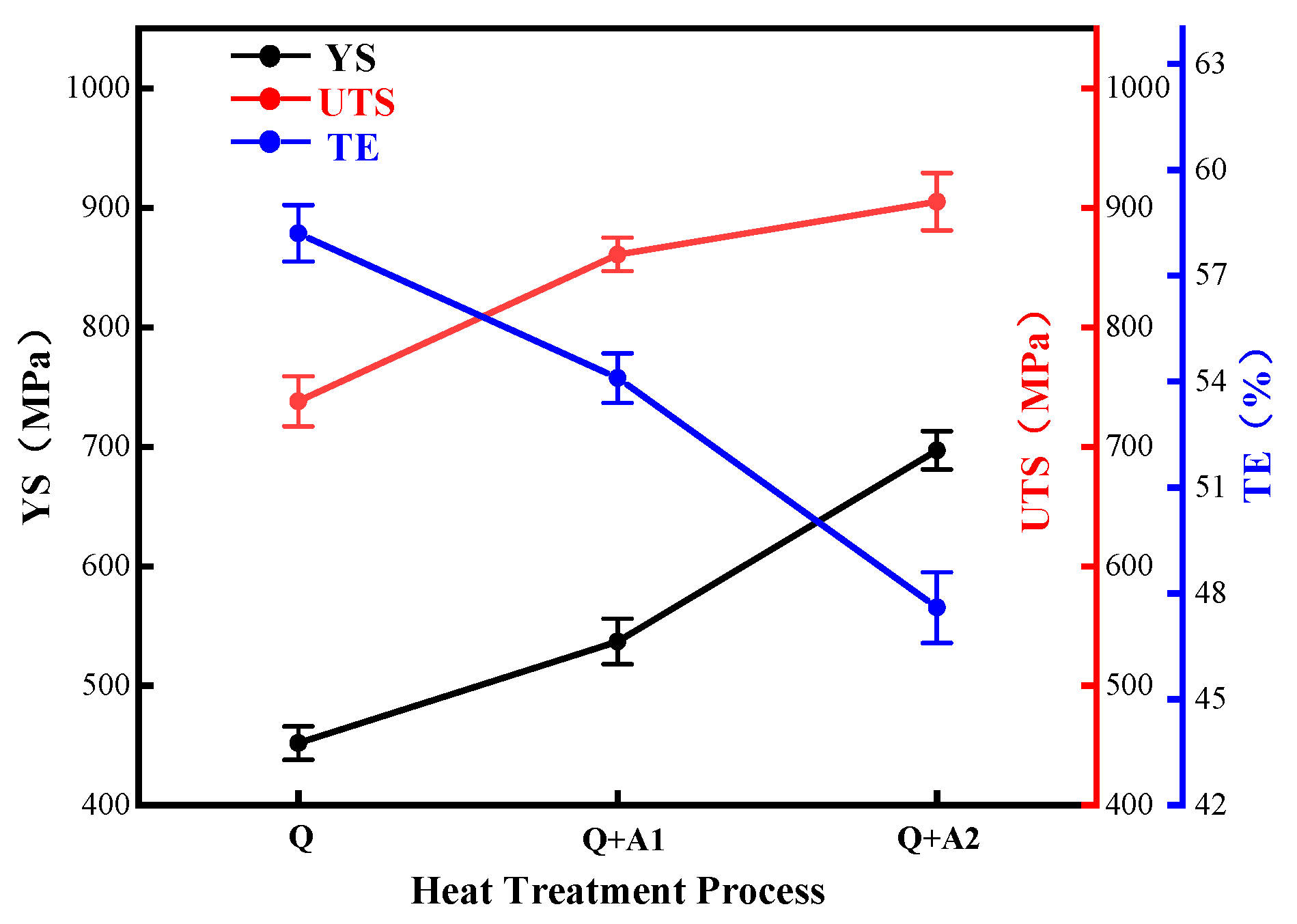
  • The second-phase strengthening effect of nanometer-sized κ-carbides is the main reason for the increase in strength and hardness, and the strengthening effect increases with the increase in aging temperature. The yield strength, tensile strength, and hardness of the Q + A2 process are 697 MPa, 905 MPa, and 294 HB, respectively, which are 29.8%, 5.1%, and 6.5% higher than that of the Q + A1 process. However, the continuous precipitation of large-sized κ-carbide at the grain boundary reduces the material’s toughness. Compared with the aging temperature of 500 °C and 300 °C, the elongation and impact energy at −40 °C decrease by 12.0% and 47.1%, respectively.
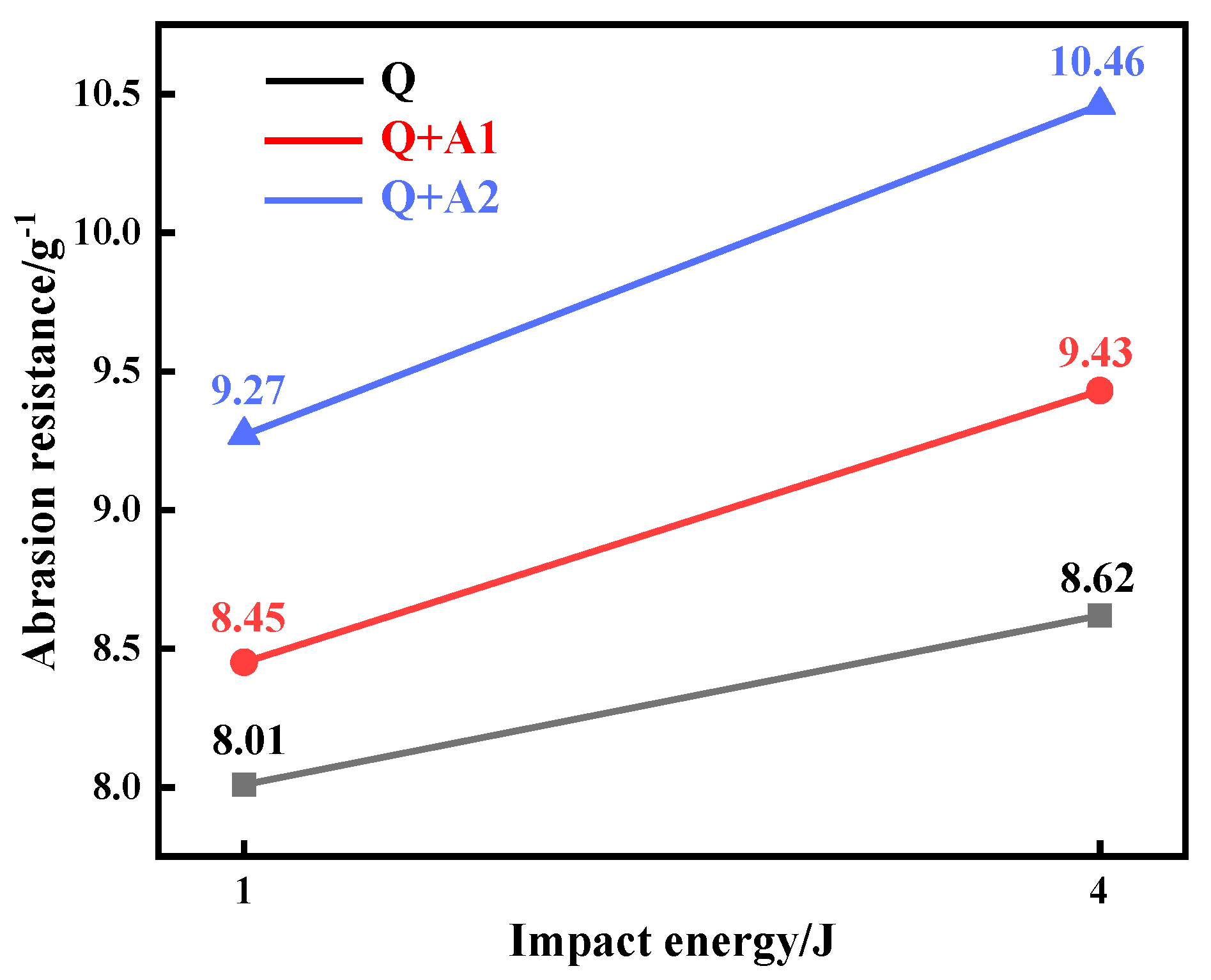
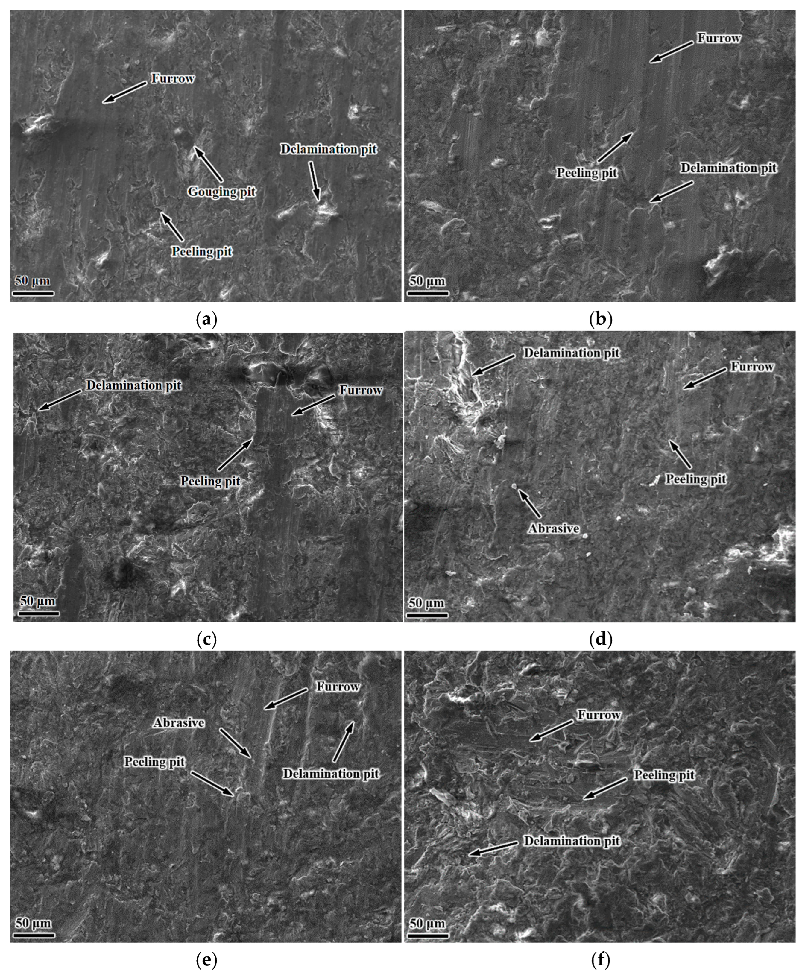
  • After aging treatment, the wear resistance of Fe-28Mn-8.5Al-1.0C material is improved. The wear resistance of Fe-28Mn-8.5al-1.0c material under the Q + A2 process is the best, and the wear resistance under 1 J and 4 J of impact energy is 9.27 g−1 and 10.46 g−1, respectively, which is 9.7% and 10.9% higher than that under the Q + A1 process, respectively. The dominant wear mechanism of the material under 4J impact energy after Q + A2 process treatment is plastic deformation. Under the different impact energy wear conditions of Q and Q + A1 heat treatment, the dominant wear mechanism of the material is micro-cutting, followed by fatigue-peeling.
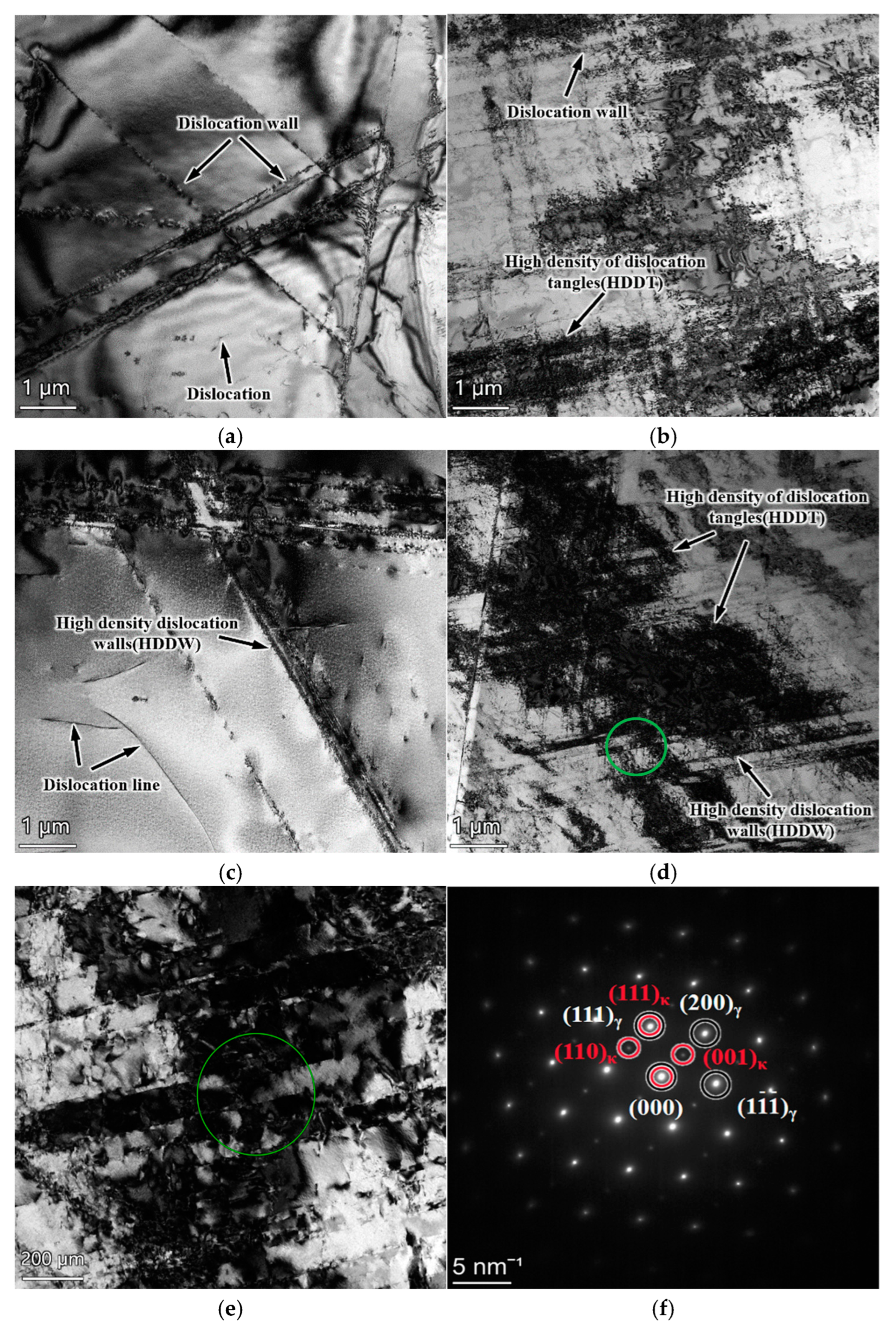
  • After aging treatment, the hardening mechanism of the subsurface of the material is the entanglement of the dislocation wall and high-density dislocation, respectively, under different impact work. With an increase in aging temperature, the blocking effect of κ-carbide on dislocation movement is enhanced, which leads to an improvement in the work-hardening effect of the wear surface of the material. Dislocation strengthening caused by the second-phase strengthening and κ-carbide hindering dislocation movement is the main reason for the improvement in the wear resistance of the material, and the combined effect of the two has a significant effect on the comprehensive properties of Fe-28Mn-8.5Al-1.0C steel.

Author Contributions

All authors contributed to the study’s conception and design. Conceptualization, M.C. and Q.W.; methodology, J.S. and S.W.; validation, L.L., S.W. and B.C.; formal analysis, Q.W.; investigation, M.C. and J.S.; resources, Q.W. and J.S.; data curation, L.L. and B.C.; writing—original draft preparation, L.L.; writing—review and editing, L.L.; supervision, Q.W.; project administration, J.S. and S.W.; funding acquisition, J.S. and M.C. All authors have read and agreed to the published version of the manuscript.

Funding

This research was funded by the State Key Laboratory of Metastable Material Preparation Technology and Science of Yanshan University and Taiyuan Heavy Industry Co., Ltd., grant number 202102050201002.

Data Availability Statement

The original contributions presented in the study are included in the article, further inquiries can be directed to the corresponding author.

Acknowledgments

This paper is based on the “Research and development of basic and application technology of new high-performance lightweight wear-resistant steel materials”. Thanks are given to the State Key Laboratory of Metastable Material Preparation Technology and Science of Yanshan University, Taiyuan Heavy Industry Co., Ltd., and other relevant units for their technical, experimental, and financial support. (Grant No. 202102050201002).

Conflicts of Interest

Authors Jianchang Sun and Mintao Chen were employed by the Taiyuan Heavy Industry Company Limited. The remaining authors declare that the research was conducted in the absence of any commercial or financial relationships that could be construed as a potential conflict of interest. Besides, the authors declare that this study received funding from Taiyuan Heavy Industry Co., Ltd. The funder was not involved in the study design, collection, analysis, interpretation of data, the writing of this article or the decision to submit it for publication.

References

  1. Sun, W.; Ning, L. Measures to improve the performance of high manganese steel crushing teeth. Cast. Equip. Technol. 2011, 4, 30–32. [Google Scholar]
  2. Lin, Y.C.; Wang, S.W.; Chen, T.M. A study on the wear behavior of hardened medium carbon steel. J. Mater. Process. Technol. 2002, 120, 126–132. [Google Scholar] [CrossRef]
  3. Dastur, Y.N.; Leslie, W.C. Mechanism of work hardening in Hadfield manganese steel. Met. Trans. A 1981, 12, 749–759. [Google Scholar] [CrossRef]
  4. Abbasi, M.; Kheirandish, S.; Kharrazi, Y.; Hejazi, J. On the comparison of the abrasive wear behavior of aluminum alloyed and standard Hadfield steels. Wear 2010, 268, 202–207. [Google Scholar] [CrossRef]
  5. Tianfu, J.; Fucheng, Z. The Work-hardening behavior of medium manganese steel under impact abrasive wear condition. Mater. Lett. 1997, 31, 275–279. [Google Scholar] [CrossRef]
  6. Yan, W.; Fang, L.; Sun, K.; Xu, Y. Effect of surface work hardening on wear behavior of hadfield steel. Mater. Sci. Eng. A 2007, 460–461, 542–549. [Google Scholar] [CrossRef]
  7. Zhang, G.-S.; Xing, J.-D.; Gao, Y.-M. Impact wear resistance of WC/Hadfield steel composite and its interfacial characteristics. Wear 2006, 260, 728–734. [Google Scholar] [CrossRef]
  8. Lu, D.S.; Liu, Z.Y.; Li, W.; Liao, Z.; Tian, H.; Xian, J.Z. Influence of carbon content on wear resistance and wear mechanism of Mn13Cr2 and Mn18Cr2 cast steels. China Foundry 2015, 12, 39–47. [Google Scholar]
  9. Yan, H.; Xie, W.; Wang, W.; Li, J.; Wang, A.; Li, L. Study on microstructure and properties of alloyed high manganese steel ZGMn13CrMo. Hot Work. Technol. 2006, 35, 11–13. [Google Scholar]
  10. Brüx, U.; Frommeyer, G.; Grässel, O.; Meyer, L.W.; Weise, A. Development and characterization of high strength impact resistant Fe-Mn-(Al-, Si) TRIP/TWIP steels. Steel Res. 2002, 73, 294–298. [Google Scholar] [CrossRef]
  11. Liu, C.; Peng, Q.; Xue, Z.; Wu, T. Research status of Fe-Mn-Al-C series low density high strength steels. Mater. Rev. 2019, 33, 2572–2581. [Google Scholar]
  12. Lins, V.F.; Freitas, M.A.; e Silva, E.M. Corrosion resistance study of Fe–Mn–Al–C alloys using immersion and potentiostatic tests. Appl. Surf. Sci. 2005, 250, 124–134. [Google Scholar] [CrossRef]
  13. Wang, C.-J.; Chang, Y.-C. NaCl-induced hot corrosion of Fe–Mn–Al–C alloys. Mater. Chem. Phys. 2002, 76, 151–161. [Google Scholar] [CrossRef]
  14. Cheng, W.C.; Cheng, C.Y.; Hsu, C.W.; Laughlin, D.E. Phase transformation of the L1 2 phase to Kappa-carbide after spinodal decomposition and ordering in an Fe–C–Mn–Al austenitic steel. Mater. Sci. Eng. A 2015, 642, 128–135. [Google Scholar] [CrossRef]
  15. Wang, F.; Sun, T.; Wang, M.; Zhou, X.; Shi, J. Research progress of Fe-Mn-Al-C series Austenitic low density steels. Iron Steel 2021, 56, 89–102. [Google Scholar]
  16. Peng, S.; Song, R.; Cai, C.; Pei, Z.; Guo, K.; Wangn, Z.; Gao, J. Impact wear properties and mechanism of new lightweight Austenitic wear-resistant steels. Chin. J. Mater. Res. 2017, 31, 537–546. [Google Scholar]
  17. Ba, Q.; Song, R.; Zhou, N.; Pei, Z.; Feng, Y.; Song, R. Revealing working hardening behavior and substructure evolutions of ultrahigh strength and enhanced wear resistance Fe-25Mn-7Al-1C steel treated by explosion processing. J. Mater. Sci. 2020, 55, 1256–1268. [Google Scholar] [CrossRef]
  18. Zheng, Z.B.; Yang, H.K.; Shatrava, A.P.; Long, J.; Wang, Y.H.; Li, J.X.; Zheng, K.H. Work hardening behavior and fracture mechanisms of Fe-18Mn-1.3C-2Cr low-density steel castings with varying degrees proportions of aluminum alloying. Mater. Sci. Eng. A 2023, 862, 144467. [Google Scholar] [CrossRef]
  19. Sun, J.; Huang, Z.; Li, J.; Wang, P. Effect of Solution and Aging Treatment on Microstructure and Hardness of Fe-Mn-Al-C Light steel. Heat Treat. Met. 2022, 47, 34–39. [Google Scholar]
  20. Liu, S.; Li, S.; Bai, H.; Zhang, X.; Ding, H. Effect of Annealing and Aging on Microstructure and Properties of Fe-12Mn-7Al-0.6C-0.5V Low Density Steel. J. Mater. Metall. 2020, 12, 134–141. [Google Scholar]
  21. Wang, H.T.; Tao, N.R.; Lu, K. Strengthening an austenitic Fe–Mn steel using nanotwinned austenitic grains. Acta Mater. 2012, 60, 4027–4040. [Google Scholar]
  22. Shin, J.-H.; Rim, G.-Y.; Kim, S.-D.; Jang, J.H.; Park, S.-J.; Lee, J. Effects of aging Heat-treatment on dynamic strain aging behavior in high-Mn lightweight steel. Mater. Charact. 2020, 164, 110316. [Google Scholar] [CrossRef]
  23. Jeong, J.; Lee, C.Y.; Park, I.J.; Lee, Y.K. Isothermal precipitation behavior of κ-carbide in the Fe–9Mn–6Al–0.15C lightweight steel with a multiphase microstructure. J. Alloys Compd. 2013, 574, 299–304. [Google Scholar] [CrossRef]
  24. Lu, W.J.; Zhang, X.F.; Qin, R.S. κ-carbide hardening in a low-density high-Al high-Mn multiphase steel. Mater. Lett. 2015, 138, 96–99. [Google Scholar]
  25. Kim, J.; Estrin, Y.; De Cooman, B.C. Application of a dislocation density-based constitutive model to Al-alloyed TWIP steel. Met. Mater. Trans. A 2013, 44, 4168–4182. [Google Scholar] [CrossRef]
  26. Kim, H.; Suh, D.-W.; Kim, N.J. Fe–Al–Mn–C lightweight structural alloys: A review on the microstructures and mechanical properties. Sci. Technol. Adv. Mater. 2013, 14, 014205. [Google Scholar]
  27. Kalashnikov, I.; Acselrad, O.; Shalkevich, A.; Chumakova, L.; Pereira, L. Heat treatment and thermal stability of FeMnAlC alloys. J. Mech. Work. Technol. 2003, 136, 72–79. [Google Scholar] [CrossRef]
  28. Hwang, C.N.; Liu, T.F. The as-quenched microstructures of Fe-9Al-30Mn-1.2C-xSi alloys. Scr. Mater. 1997, 36, 853–859. [Google Scholar] [CrossRef]
  29. Bartlett, L.N.; Van Aken, D.C.; Medvedeva, J.; Isheim, D.; Medvedeva, N.I.; Song, K. An atom probe study of kappa carbide precipitation and the effect of silicon addition. Met. Mater. Trans. A 2014, 45, 2421–2435. [Google Scholar] [CrossRef]
  30. Chen, S.; Rana, R.; Haldar, A.; Ray, R.K. Current state of Fe-Mn-Al-C low density steels. Prog. Mater. Sci. 2017, 89, 345–391. [Google Scholar]
  31. Zhang, X.; Li, J.; Wan, Y.; Wu, X.; Huang, Z. Research progress of ordered precipitates in low density steels. Mater. Rev. 2019, 33, 3979–3989. [Google Scholar]
  32. Lu, W.J.; Qin, R.S. Influence of κ-carbide interface structure on the formability of lightweight steels. Mater. Des. 2016, 104, 211–216. [Google Scholar]
  33. Ren, P.; Chen, X.P.; Mei, L.; Nie, Y.Y.; Cao, W.Q.; Liu, Q. Intragranular brittle precipitates improve strain hardening capability of Fe–30Mn–11Al–1.2C low-density steel. Mater. Sci. Eng. A 2020, 775, 138984. [Google Scholar] [CrossRef]
  34. Frommeyer, G.; Brüx, U. Microstructures and Mechanical Properties of High-Strength Fe-Mn-Al-C Light-Weight TRIPLEX steels. Steel Res. Int. 2006, 77, 627–633. [Google Scholar]
  35. Cheng, W.-C. Phase transformations of an Fe-0.85 C-17.9 Mn-7.1 Al austenitic steel after quenching and annealing. JOM 2014, 66, 1809–1820. [Google Scholar]
  36. Wu, H.; Ju, B.; Tang, D.; Hu, R.; Guo, A.; Kang, Q.; Wang, D. Effect of Nb addition on the microstructure and mechanical properties of an 1800MPa ultrahigh strength steel. Mater. Sci. Eng. A 2015, 622, 61–66. [Google Scholar] [CrossRef]
  37. Ji, F.Q.; Li, C.N.; Tang, S.; Liu, Z.Y.; Wang, G.D. Effects of carbon and niobium on microstructure and properties for Ti bearing steels. Mater. Sci. Technol. 2015, 31, 695–702. [Google Scholar]
  38. Li, Z.; Wang, Y.; Cheng, X.; Li, Z.; Du, J.; Li, S. The effect of Ti-Mo-Nb on the microstructures and tensile properties of a Fe-Mn-Al-C austenitic steel. Mater. Sci. Eng. A 2020, 780, 139220. [Google Scholar] [CrossRef]
  39. Yao, M.; Welsch, E.; Ponge, D.; Haghighat, S.; Sandlöbes, S.; Choi, P.; Herbig, M.; Bleskov, I.; Hickel, T.; Lipinska-Chwalek, M.; et al. Strengthening and strain hardening mechanisms in a precipitation-hardened high-Mn lightweight steel. Acta Mater. 2017, 140, 258–273. [Google Scholar] [CrossRef]
  40. Kim, J.; Lee, S.-J.; De Cooman, B.C. Effect of Al on the stacking fault energy of Fe–18Mn–0.6C twinning-induced plasticity. Scr. Mater. 2011, 65, 363–366. [Google Scholar]
  41. Cao, C.; Wang, C.; Cao, W. Formation mechanism of κ-carbide in FeMnAlC low-density steel. Heat Treat. Met. 2021, 46, 1–6. [Google Scholar]
  42. Kim, C.; Terner, M.; Hong, H.U.; Lee, C.H.; Park, S.J.; Moon, J. Influence of inter/intra-granular κ-carbides on the deformation mechanism in lightweight Fe-20Mn-11.5Al-1.2C steel. Mater. Charact. 2020, 161, 110142. [Google Scholar]
  43. Lu, Z.-L.; Zhou, Y.-X.; Rao, Q.-C.; Jin, Z.-H. An investigation of the abrasive wear behavior of ductile cast iron. J. Mech. Work. Technol. 2001, 116, 176–181. [Google Scholar] [CrossRef]
  44. Yan, H.; Xie, J.; Wang, W.Y.; Li, J.; Li, L. Study on wear resistance of ultra-high manganese steel and wear behavior of impact abrasives. Foundry Technol. 2007, 28, 618–621+627. [Google Scholar]
  45. Liu, Y.; Wei, S.; Zang, M. Microstructure and wear resistance of Light weight high Manganese steel. Tribology 2018, 38, 291–298. [Google Scholar]
  46. Peng, S.-G.; Song, R.-B.; Tan, Z.-D.; Cai, C.H.; Guo, K.; Wang, Z.-H. Abrasive Wear behaviors of light-weight austenitic Fe-24Mn-7Al-1C steel and Mn13Cr2 steel. J. Iron Steel Res. Int. 2016, 23, 857–866. [Google Scholar] [CrossRef]
  47. Wang, Y.; Si, S. Study on work hardening law and mechanism of high manganese steel. Iron Steel 2001, 10, 54–56. [Google Scholar]
  48. Feng, Y. Study on Strengthening Mechanism and Impact Wear Behavior of Age-Hardened Lightweight Ultra-High Manganese Steel. Ph.D. Thesis, University of Science and Technology Beijing, Beijing, China, 2021. [Google Scholar]
  49. Gutierrez-Urrutia, I.; Raabe, D. Multistage strain hardening through dislocation substructure and twinning in a high strength and ductile weight-reduced Fe–Mn–Al–C steel. Acta Mater. 2012, 60, 5791–5802. [Google Scholar]
  50. Chang, K.M.; Chao, C.G.; Liu, T.F. Excellent combination of strength and ductility in an Fe–9Al–28Mn–1.8C alloy. Scr. Mater. 2010, 63, 162–165. [Google Scholar]
  51. Meng, L.; Liang, W.; Zhao, X.; Li, X. Effect of strain rate on the size of pure iron dislocation cells. J. Electron Microsc. 2005, 24, 295. [Google Scholar]
  52. He, F.; Wang, C.; Han, B.; Yeli, G.; Lin, X.; Wang, Z.; Wang, L.; Kai, J.-J. Deformation faulting and dislocation-cell refinement in a selective laser melted 316L stainless steel. Int. J. Plast. 2022, 156, 103346. [Google Scholar] [CrossRef]
  53. Tang, J.; He, S.; Mo, Y.; Jiang, F.; Fu, D.; Teng, J.; Zhang, H. Revealing the cryogenic-temperature toughness and deformation mechanisms in high manganese austenitic steels. Mater. Charact. 2022, 190, 112024. [Google Scholar] [CrossRef]
Figure 1. The heat treatment process curve of experimental materials.
Metals 15 00178 g001
Figure 2. A structural schematic of the MLD-10B dynamic load abrasive wear-testing machine.
Metals 15 00178 g002
Figure 3. An OM image of Fe-28Mn-8.5Al-1.0C after heat treatment: (a) Q; (b) Q + A1; (c) Q + A2.
Metals 15 00178 g003
Figure 4. XRD and local magnification of Fe-28Mn-8.5Al-1.0C after heat treatment: (a) XRD pattern; (b) local enlarged pattern.
Metals 15 00178 g004
Figure 5. TEM images of Fe-28Mn-8.5Al-1.0C after different heat treatment processes,: (a,b) DF image and SAED image after the Q process; (c,d) DF image and SAED image after the Q + A1 process; (e,f) DF image and SAED image after Q + A2; (g,h) DF image and SAED image of (Fe, Mn)3AlC κ-carbide at the grain boundary after the Q + A2 process.
Metals 15 00178 g005
Figure 6. The strength and elongation gradient curves of Fe-28Mn-8.5Al-1.0C under different heat treatment conditions.
Metals 15 00178 g006
Figure 7. The impact wear resistance of Fe-28Mn-8.5Al-1.0C under heat treatment conditions.
Metals 15 00178 g007
Figure 8. A statistical figure of KAM and the average value of the wear edge of Fe-28Mn-8.5Al-1.0C material under different impact energies after aging treatment: (a,c) Q + A1 − 1 J; (b,d) Q + A1 − 4 J; (e,g) Q + A2 − 1 J; (f,h) Q + A2 −; 4 J.
Metals 15 00178 g008
Figure 9. SEM images of the worn surface of Fe-28Mn-8.5Al-1.0C after heat treatment: (a,b) Q − 1 J, 4 J; (c,d) Q + A1 − 1 J, 4 J; (e,f) Q + A2 − 1 J, 4 J.
Metals 15 00178 g009
Figure 10. The wear surface morphology of Fe-28Mn-8.5Al-1.0C after different heat treatment processes: (a,b) Q − 1 J, 4 J; (c,d) Q + A1 − 1 J, 4 J; (e,f) Q + A2 − 1 J, 4 J.
Metals 15 00178 g010
Figure 11. TEM images of the impact wear subsurface of Fe-28Mn-8.5Al-1.0C under different aging temperature conditions: (a,b) Q + A1 − 1 J, 4J; (c,d) Q + A2 − 1 J, 4J; (e,f) Q + A2 − 4 J and SAED.
Metals 15 00178 g011
Table 1. The chemical composition of the test materials (mass%).
MaterialsMnCAlSiPS
Fe-28Mn-8.5Al-1.0C27.411.028.260.230.0160.005
Table 2. The mechanical properties of Fe-28Mn-8.5Al-1.0C after different heat treatment processes.
ProcessRp0.2/MPaRm/MPaA/%−40 °C KV2/JHardness (HB)
Q452 ± 14738 ± 2158.2 ± 0.8144 ± 4257 ± 8
Q + A1537 ± 19861 ± 1454.1 ± 0.7102 ± 6276 ± 5
Q + A2697 ± 16905 ± 2447.6 ± 1.054 ± 6294 ± 7
Note: Rp0.2—yield strength; Rm—tensile strength; A—elongation.
Table 3. The wear resistance of Fe-28Mn-8.5Al-1.0C material.
ProcessImpact Energy/JWeight Before Wear/g (±0.3 mg)Weight After Wear/g (±0.3 mg)W/gε/g−1Initial HardnessFinal Hardness
Q119.749719.62490.12488.01257321
419.972919.85690.11608.62405
Q + A1119.773819.65550.11838.45276377
419.850619.74460.10609.43438
Q + A2119.879319.77140.10799.27294384
419.932319.83670.095610.46452
Disclaimer/Publisher’s Note: The statements, opinions and data contained in all publications are solely those of the individual author(s) and contributor(s) and not of MDPI and/or the editor(s). MDPI and/or the editor(s) disclaim responsibility for any injury to people or property resulting from any ideas, methods, instructions or products referred to in the content.

