Article

Influence of Sulfide Concentration on the Properties of Cr3C2-25(Ni20Cr) Cermet Coating on Al7075 Substrate

by
Mieczyslaw Scendo
Institute of Chemistry, Jan Kochanowski University in Kielce, Uniwersytecka 7, PL-25406 Kielce, Poland
Metals 2025, 15(3), 273; https://doi.org/10.3390/met15030273
Submission received: 24 January 2025 / Revised: 27 February 2025 / Accepted: 28 February 2025 / Published: 2 March 2025
(This article belongs to the Special Issue Corrosion Behavior of Alloys in Water Environments)

Abstract

:
The influence of sulfide (S2−) concentration on the corrosion resistance of Cr3C2-25(Ni20Cr) cermet coating on Al7075 (EN, AW-7075) substrate (Cr3C2-25(Ni20Cr)/Al7075) was investigated. The coating was produced by the cold-sprayed (CS) method. The Cr3C2-25(Ni20Cr)/Al7075 coatings were modified chemically in solutions containing thioacetic acid amide (TAA). The surface and microstructure of the specimens were both observed by a scanning electron microscope (SEM). The mechanical properties of the Cr3C2-25(Ni20Cr) coatings were characterized using microhardness (HV) measurements. The corrosion tests of the materials were carried out using the electrochemical method in a acidic chloride solution. The adsorbed (MemSn)ads layer effectively separates the Cr3C2-25(Ni20Cr)/Al7075 coating surface from contact with the aggressive corrosive environment. More than a twice lower value of corrosion rate (CW) was obtained for the Cr3C2-25(Ni20Cr)/Al7075 coating after exposure to the environment with 0.15 M TAA.

1. Introduction

Aluminum and its alloys offer a wide range of properties that can be engineered for specific demands. Aluminum–zinc–magnesium alloys have a greater response to heat treatment than binary aluminum–zinc alloys, resulting in higher strengths. The additions of zinc and magnesium, however, decrease the corrosion resistance. Thus, the alloys (i.e., Al7075) must be protected against corrosion, most often by means of metallic coatings resistant to corrosion. For this purpose, titanium or nickel coatings are very often used [1]. One of the most effective ways to improve the corrosion resistance of materials is to cover their surfaces with composite coatings, which significantly increases the durability and improves the mechanical properties of metal structures [2]. Surface modification by applying coatings is used in manufacturing industries to enhance surface properties. Surface coatings protect the base material and produce cost savings with respect to component replacement, material degradation, and the service life of the coated components [3,4]. Modern technological developments in the field of engineering surfaces, in particular implemented in hybrid systems, being effective in the last dozen or so years, have created great opportunities in the field of the production applications of complex coatings, i.e., multi-layer, gradient, multi-component, as well as composite materials, and have various properties and microstructures. One of the main directions of surface engineering is the production of coatings adapted (functionally) to specific applications in various industries [5]. An example of a functional coating is the Cr3C2-NiCr composite coating, consisting of hard chromium carbide particles embedded in a soft Ni/Cr phase matrix. The thermal spraying of fine Cr3C2-NiCr often includes chemical degradation of the chromium carbides present in the feedstock powder. The Cr3C2-NiCr coatings are most often deposited by high-velocity oxygen spray (HVOF) and plasma spray (PS) methods [6,7]. Currently, use of the cold spray (CS) method is recommended. The cold spray method enables the deposition of coating layers with a microstructure containing the Cr3C2 carbide phase, which ensures better mechanical properties of the coating on metal substrates [8]. The cold spray method for the production of Cr3C2-NiCr coatings can greatly reduce negative effects, such as thermally induced phase reactions and the decomposition effects of fine Cr3C2-NiCr powders. Various methods are used to remove cermet coating defects, such as heat treatment, sealing, laser remelting, and others. The CS process is governed by the impact of high-velocity feedstock particles (5–50 µm in diameter) onto a substrate without melting. The particles cause ballistic impingement on a suitable substrate at speeds ranging between 300 and 1200 m s−1. Hence, the bulk material properties are retained. However, it is challenging to achieve good adhesion strength. The adhesion strength depends on factors such as the cold spray process parameters, substrate conditions, coating/substrate interactions at the interface, and feedstock material properties. Cold spraying is a solid-state deposition process since the feedstock is not melted. However, the kinetic energy of the high-velocity particles leads to interfacial deformation as well as localized heat at the point of impact. The conversion of kinetic energy into deformation and heat results in mechanical interlocking as well as metallurgical bonding at the interface [9,10]. Conventional Cr3C2-NiCr coatings have been previously employed to apply carbide cermet coating onto industrial equipment due to its excellent resistance to wear, erosion, and thermal shock, as well as its high temperature stability. The properties of these coatings depend on certain primary factors, including the variety of deposition methods (parameters) and the microstructure of the coatings [11,12]. Furthermore, coatings containing chromium carbide particles (cermet coating), distributed in a nickel-chromium alloy matrix, i.e., Cr3C2-NiCr, are often used for corrosion and wear-resistant applications. The combination of the ceramic and metal phases means that a higher fracture strength can be achieved. The improvement in hardness is directly associated with higher particle velocities and increased densities of the Cr3C2-NiCr-based coatings deposited on the substrate at ambient temperatures. The corrosion resistance of the cermet coatings is also associated with the surface roughness: the higher the surface roughness, the higher the corrosion attack, due to the higher surface area [13]. Chromium carbides are easily combined with a softer metal phase to form composite cermet systems. In particular, Ni-Cr metal alloys are used to facilitate carbide deposition, while also improving the strength and ductility of cermet coatings [14,15]. In addition, the nickel-chromium binder improves erosion and corrosion resistance due to the higher percentage of chromium in the coating. However, Cr3C2-NiCr coatings are very sensitive to the deposition technique used and the appropriately selected spray parameters [16]. Cr3C2-NiCr system coatings can be used in corrosive environments at service temperatures up to 800 to 900 °C. Therefore, Cr3C2-NiCr coatings are frequently used as protective coatings for applications in corrosive environments at elevated temperatures. Recently, various attempts have been made to modify the structure of cermet coatings. One of these involved the use of laser processing to modify the surface structure of cermet coatings [17]. Laser remelting has a significant influence on the surface structure of cermet coatings. At the lowest speed (i.e., 600 mm/min), the flattest, most regular, and most compact cermet surface on an Al7075 substrate was obtained. Moreover, a cheap and effective method of modifying the surface structure of Cr3C2-NiCr coatings is heat treatment [18]. It transpired that heating cermet coatings at a temperature of 300 °C improves the surface structure, and thus significantly increases the mechanical and anti-corrosion properties of Cr3C2-5Ni20Cr/Al7075 coatings.
Effective methods for improving the structure and properties of Cr3C2-NiCr coatings are still being sought. It appears that one of them may involve the modification of the surface structure of the coatings by a chemical method, which consists of creating a durable additional protective coating on the cermet surface.
In the present study, the influence of sulfide concentration on the properties of the Cr3C2-25(Ni20Cr) cermet coatings on an Al7075 substrate was investigated. The cermet coatings were chemically modified in thioacetic acid amide solutions. The samples were then subjected to corrosion tests in an acidic chloride solution. Corrosion parameters were determined using the electrochemical method.

2. Material and Experimental Methods

The chemical composition of the Al7075 (EN, AW-7075) alloy is as follows (wt%): 5.6% Zn, 2.5% Mg, 1.6% Cu; Cr < 0.50% are admixtures (i.e., Mn, Fe, and Si); the rest is aluminum. Fine irregular and broken Cr3C2-25(Ni20Cr) (Diamalloy 3004, Oerlikon Metco Inc., Westbury, NY, USA) was employed as feedstock material. This was a mixture of Cr3C2 and Ni20Cr powders in a weight ratio of 75% and 25%.
The morphologies and microstructures were observed using a scanning electron microscope (SEM) Joel (Tokyo, Japan), JSM-5400. The accelerating voltage of the SEM was 20 kV. Prior to the cross-sectional analysis, the coating samples were polished with increasingly fine, i.e., 3 μm, 1 μm, and 0.25 μm, diamond suspensions. X-ray diffraction (XRD) was applied to characterize the phase composition of the cold-sprayed coatings using a Bruker D8 Discover diffractometer (Bruker Ltd., Malvern, UK), with Co Kα radiation of wavelength λ = 1.7889 Å.
A scanning electron microscopy (SEM) image of the powder morphology and the X-ray diffraction pattern of Cr3C2-25(Ni20Cr) powder are illustrated in Figure 1.
The Cr3C2 powder particles have an irregular shape, while the Ni20Cr particles have an aspherical shape; see Figure 1a. It transpired that the Cr3C2-25(Ni20Cr) powder particles were characterized by significant porosity and numerous cracks on the particle surfaces. Figure 1b shows the X-ray diffraction pattern for the used powder. Based on Figure 1b, it was found that the main peaks of the diffraction spectrum are associated with the Cr3C2 and (Cr, Ni) phases. Moreover, in order to minimize agglomeration effects, the powder was heated up to 110 °C in a convection oven for 1 h before use in the feeder system.
For the production of the Cr3C2-25(Ni20Cr) cermet coating on the Al7075 substrate (Cr3C2-25(Ni20Cr)/Al7075), an Impact Innovations 5/8 cold spraying system equipped with a Fanuc M-20iA robot (Fanuc Robotics Ltd., Oshino, Japan) was used.
The following parameters were used for the production of the cermet coatings: nitrogen pressure, 40 bar; nitrogen preheating temperature, 600 °C; spraying distance, 60 mm; traverse speed, 40 mm/s; the step size between 10 passes was 2 mm; the number of layers was 4. The Cr3C2-25(Ni20Cr) cermet coatings were deposited on the Al7075 alloy. The surface of the Al7075 substrates was prepared by blasting with corundum of size 30 (i.e., 600–710 μm). The specimen size was 310 × 110 × 5 mm3. However, the test specimens had the shape of a cuboid with dimensions of 30 × 10 × 5 mm3.
The measurement of microhardness of the tested materials was performed using the Vickers method (HV) using a Falcon 500 hardness tester of the INNOVATEST (Maastricht, The Netherlands). A load of 10 N was used for the measurements.
The Cr3C2-25(Ni20Cr)/Al7075 samples were exposed in an aqueous solution of thioacetic acid amide (TAA). The TAA concentration was varied from 0.05 M to 0.15 M. The surface of the samples was covered with a layer of sulfides.
Then, the Cr3C2-25(Ni20Cr)/Al7075 samples were subjected to a corrosion test in a solution containing 1.0 M NaCl and 0.2 M HCl (1.2 M Cl), pH 1.5.
The electrochemical experiments were carried out in a conventional three-electrode cell. All electrochemical measurements were made using a potentiostat/galvanostat PGSTAT 128N (AutoLab, Amsterdam, The Netherlands), with NOVA 1.7 software from the same company.
The working electrode was made of Al7075 alloy, which was covered with a cermet coating. The geometric surface area of the working electrode was 1.0 cm2.
A saturated calomel electrode (SCE(KCl)) was used as the reference. The counter electrode (9 cm2) was made from platinum foil (99.9% Pt).
The kinetics and mechanism of corrosion of cermet coatings were studied using the Linear Sweep Voltammetry (LSV) method. The potentiodynamic polarization curves were recorded. The curves were used to designate the corrosion electrochemical parameters, polarization resistance (Rp), and corrosion rate (CW) of the tested materials [17,18].
The chronoamperometric (ChA) curves were obtained for the potential values, which were selected on the basis of the potentiodynamic polarization curves. Three values of the working electrode potential were chosen for each material tested (i.e., one potential value concerned the cathodic process and two the anodic process).
All measurements were carried out at temperatures of 25 ± 0.5 °C, which were maintained using an air thermostat. However, the electrolytes were not deoxygenated.

3. Results and Discussion

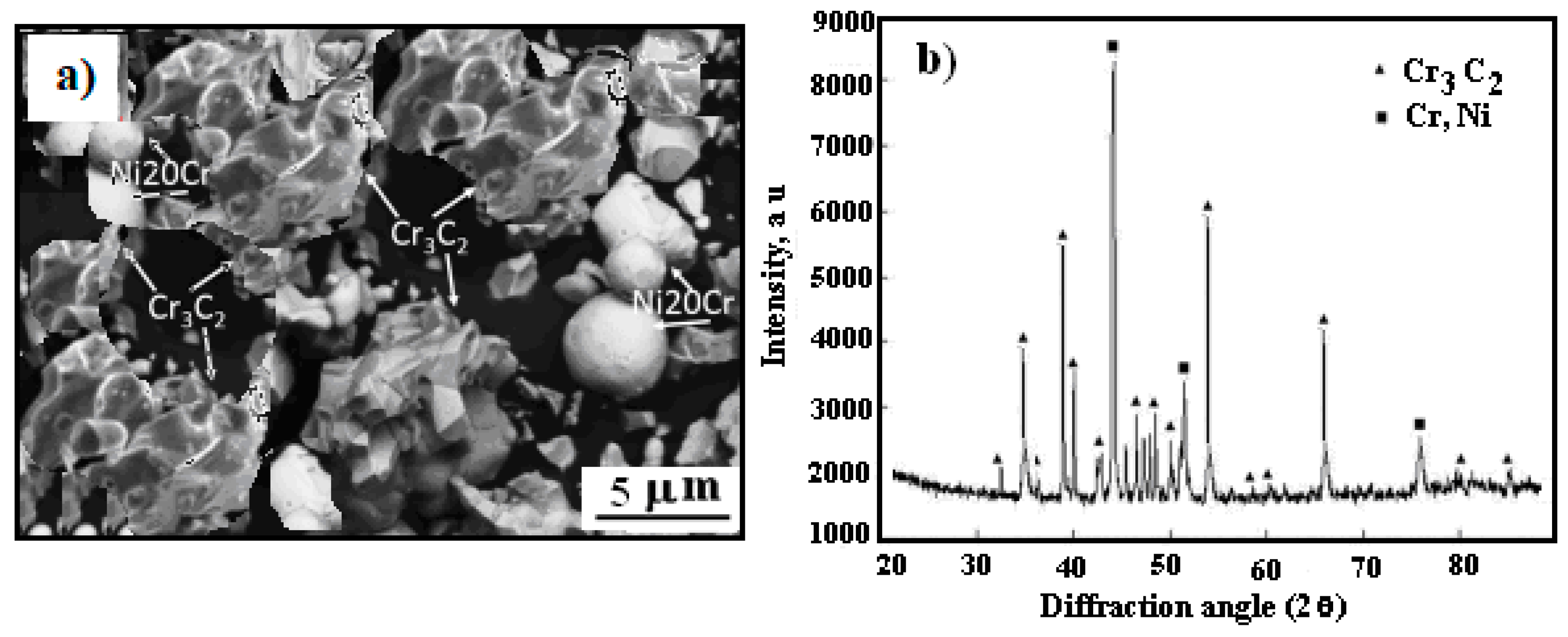
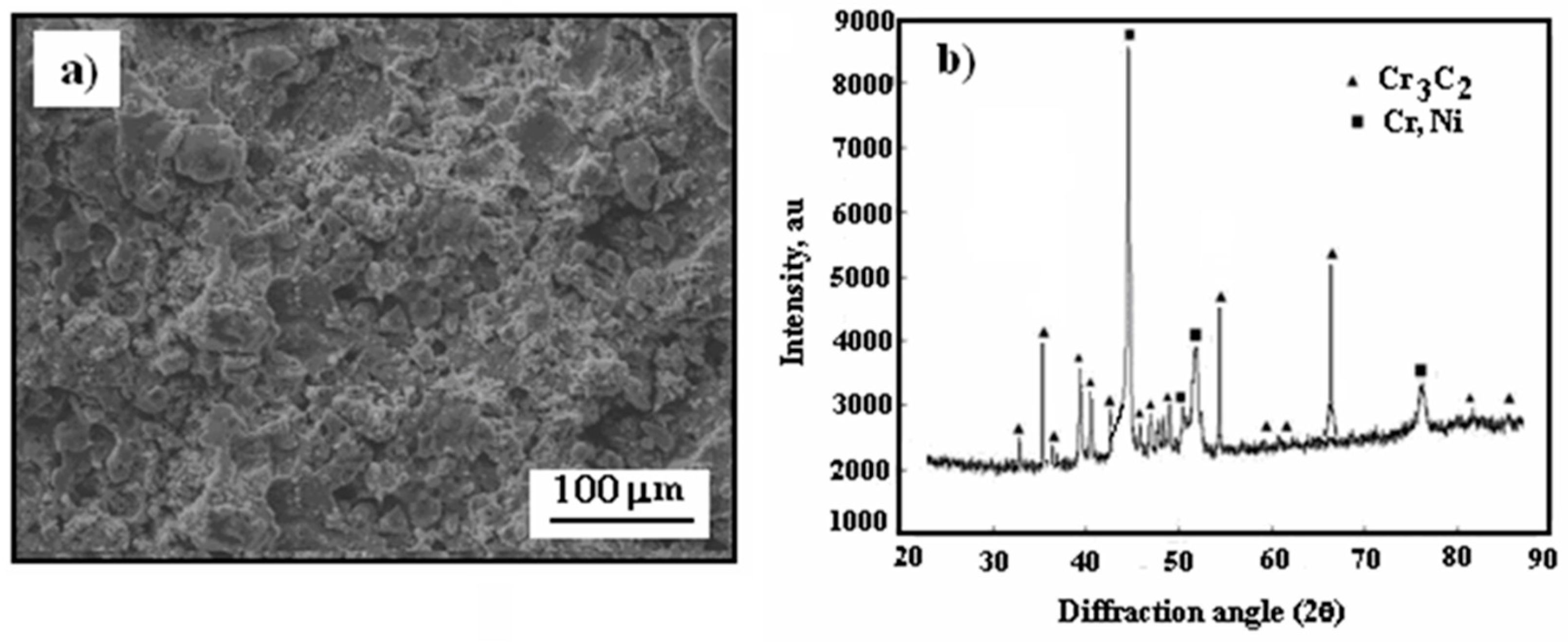
3.1. Surface Morphology

The surface morphology of the cermet coating on the Al7075 substrate and the X-ray diffraction pattern of the as-sprayed coating are presented in Figure 2.
As can be seen, the surface of the cold-sprayed cermet coating on the Al7075 substrate is tight but uneven and undulating (Figure 2a). As shown in Figure 2b, the major diffraction spectra peaks can be associated with the Cr3C2 and (Cr, Ni) phases, similar to the X-ray diffraction pattern of Cr3C2-25(Ni20Cr) powder (Figure 1b). The coating thus formed has a complex structure consisting of a hard phase mixed with a softer matrix that acts as a binder, facilitating the adhesion of the ceramic to the substrate and the cohesion between the particles, thus forming a compact and stable coating on the Al7075 substrate.

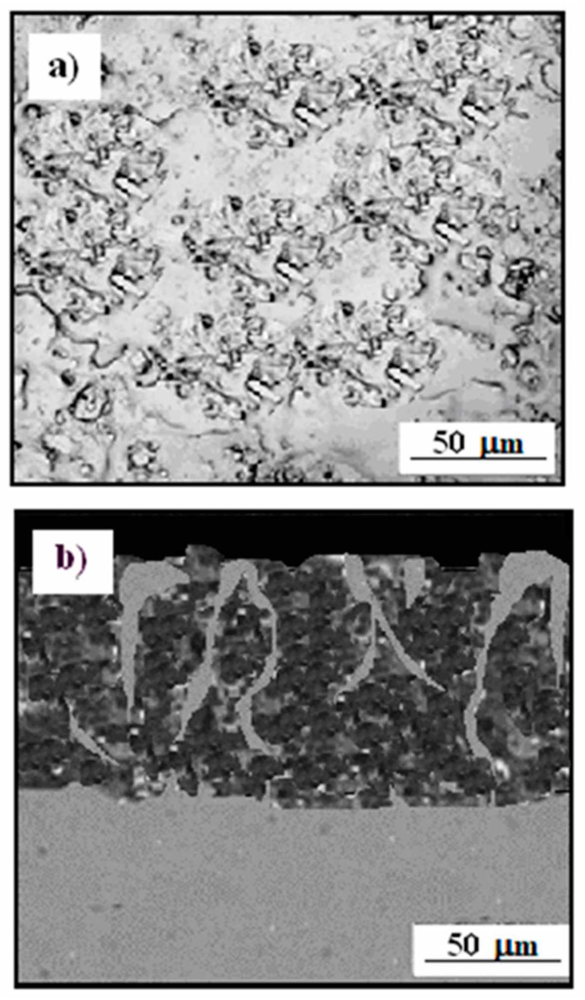
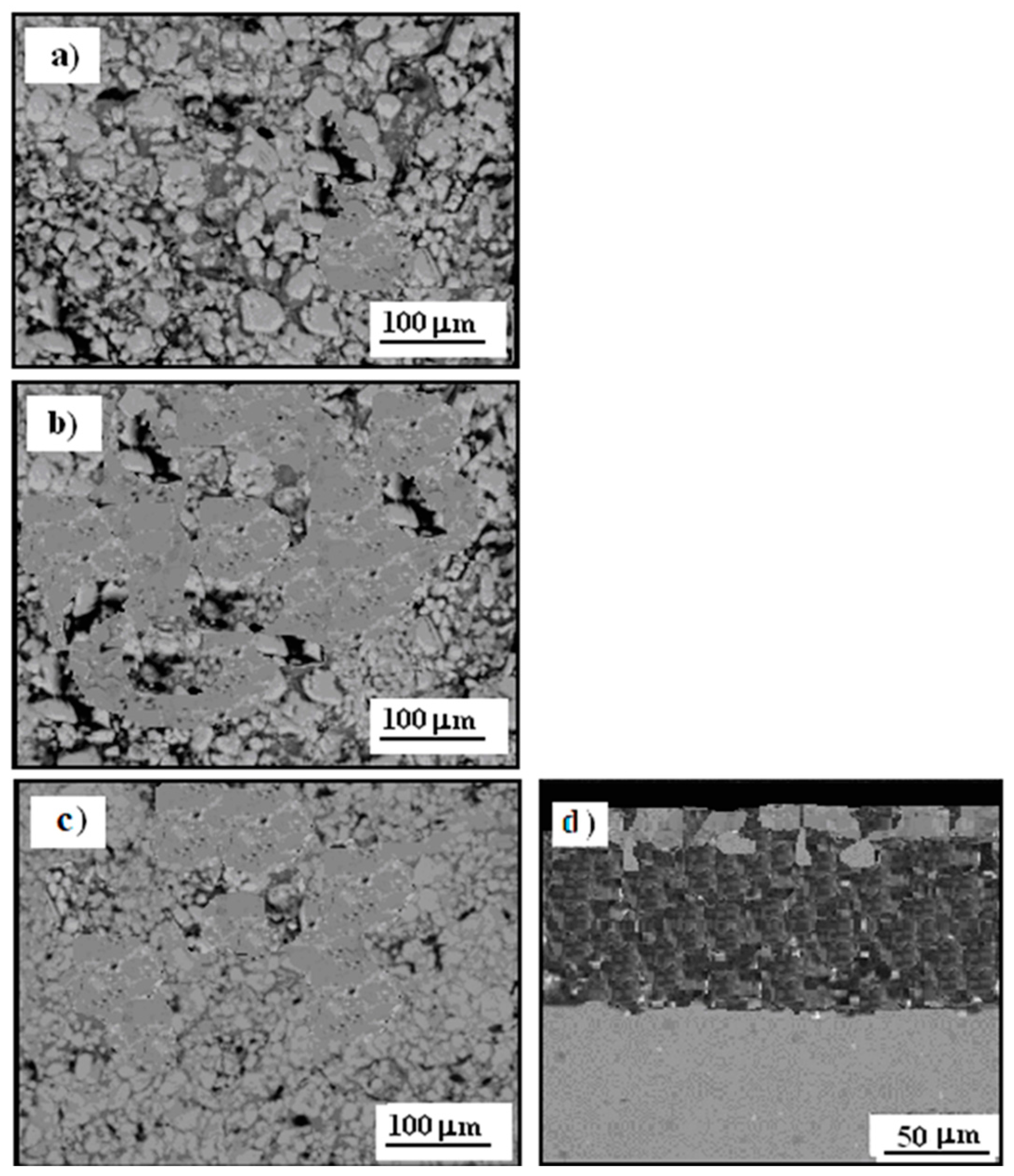
3.2. Microstructure Cermet Coating

Figure 3 shows the SEM results of the Al7075 substrate with the Cr3C2-25(Ni20Cr) cermet coating and a cross-section of the cermet coating on the Al7075 substrate.
Cermet coatings consist of a metal matrix and a hard strengthening phase. They are characterized by a number of improved mechanical properties. They are often used in industry due to their high resistance to abrasion and chemical and electrochemical corrosion. The combination of ceramic and metal phases allows for higher fracture strength, especially at elevated temperatures. The surface morphology of the Al7075 substrate is shown in Figure 3a. The surface of the substrate is smooth and homogeneous. The Cr3C2-25(Ni20Cr) coatings have a smooth surface with fine grains (Figure 3b). Cr3C2 ceramic particles are dented in the Al7075 surface. Moreover, they are much thinner compared to the powder at the initial stage. Cracking and breaking of the Cr3C2 particles into smaller fragments occurred when they hit the substrate at high speed. There are no cracks visible on the coating surface, and the microstructure is homogeneous. Cermet coatings (Figure 3c) adhere well to the substrate, no cracks are visible, and the carbide particles are closely packed. As can be seen, the coatings consist of different shading contrast zones of dark gray, medium gray mixture, and light gray, which can be distinguished by a lighter and darker contrast in the coating microstructure. The dark gray area of the Cr3C2-25(Ni20Cr)/Al7075 coating contained NiCr and C; thus, the dark gray area was considered to be carbides. The observed light gray area is mainly attributed to chromium carbides, i.e., Cr3C2 and Cr7C3. The thicknesses of the sprayed cermet coatings were in the range of 152 to 158 μm. (Figure 3c).

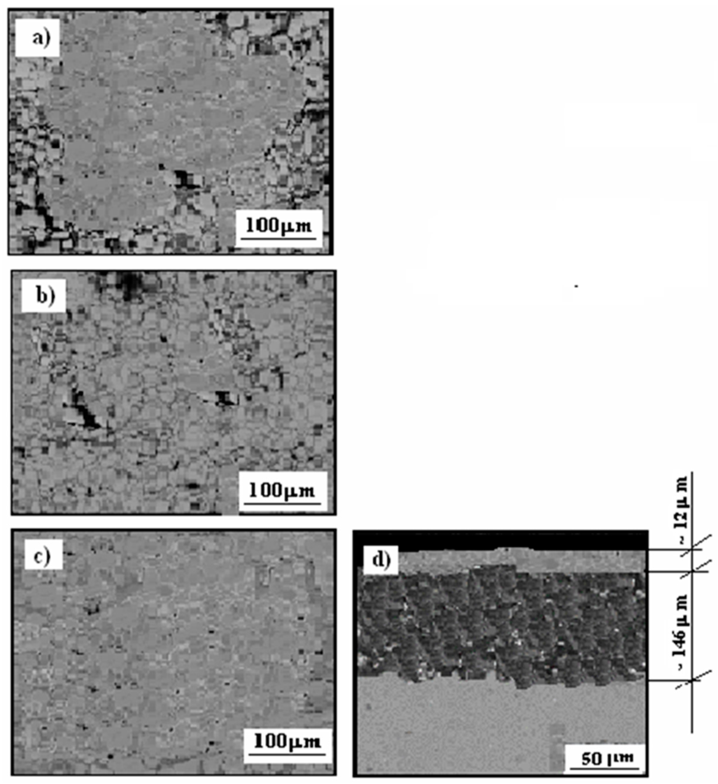
3.3. Microstructure Cermet Coating After Exposure to Corrosive Environment

Figure 4 shows SEM images of the surface of the Cr3C2-25(Ni20Cr) cermet coating on the Al7075 substrate (Figure 4a), and a cross-section of Cr3C2-25(Ni20Cr)/Al7075 (Figure 4b) after 24 h exposure in an environment of 1.2 M Cl (pH 1.5). The surface of the tested sample was significantly damaged; as a result of a simple chemical reaction, numerous deep pits appeared:
m Me0 + n Cl → (MemCln)ads
(MemCln)ads + 2H+ → m Mez+ + n Cl + H2
where Me indicates Cr, Ni, and other metals.
The Cr3C2-25(Ni20Cr)/Al7075 surface shows numerous pits that resulted from corrosion of the cermet coating (Figure 4a). As a result of corrosion (Reactions (1) and (2)), the surface of the tested sample becomes rough, and the mechanical properties of the cermet coating deteriorate.
In order to determine the structure and depth of the pits, cross-sectional photos of the tested sample were taken (Figure 4b). It should be noted that, as a result of exposure to an aggressive chloride environment, the Cr3C2-25(Ni20Cr)/Al7075 cermet coating structure was significantly damaged. Numerous deep pits were observed, reaching the substrate of the tested sample.

3.4. Cermet Coating After Exposure in Thioacetic Acid Amide

Thioacetic acid amide (TAA) dissolves in water, and in an acidic environment it undergoes a hydrolysis reaction according to:
CH3CSNH2 + 2 H2O → CH3COONH4 + 2 H+ + S2−
Therefore, the TAA was the source of S2− ions (Reaction (3)) during the exposure of the samples to the corrosive environment.
Figure 5 shows the scanning electron microscopy (SEM) image of the surface morphology of the Cr3C2-25(Ni20Cr) cermet coatings on the Al7075 substrate, and a cross-section of the selected sample after exposure in the solutions with thioacetic acid amide. However, the TAA concentration was selected experimentally and varied from 0.05 to 0.15 M. The exposure time was 24 h.
It should be assumed that the Cr3C2-25(Ni20Cr)/Al7075 cermet surface was covered with a thin layer of the product of the following chemical reaction:
m Me0 + 2 H+ + n S2− → (MemSn)ads + H2
To increase the reaction efficiency (4), the solution was vigorously stirred and heated to 45 °C.
The adsorption of (MemSn)ads (Reaction (4)) can act as a protective layer that separates the Cr3C2-25(Ni20Cr)/Al7075 surface from the aggressive influence of the corrosive environment. It seems that, with the increase of thioacetic acid amide concentration in the solution, increasingly tight protective (MemSn)ads coatings were obtained on the Cr3C2-25(Ni20Cr)/Al7075 cermet surface (Figure 5a,b). However, the tightest of the (MemSn)ads protective layer was obtained in the case of the electrolyte with the highest concentration of thioacetic acid amide, i.e., 0.15 M TAA (Figure 5c). The thickness of the protective layer for the highest TAA concentration was found to be approximately 12 µm (Figure 5d). Therefore, as a result of chemical modification of the cermet surface, an additional protective layer (MemSn)ads was created. In addition, the sulfide layer was smooth and adhered well to the cermet substrate.

3.5. Microhardness

Microhardness (HV10) measurements were also made of the Cr3C2-25(Ni20Cr) coatings on the Al7075 substrate after 24 h exposure in the solutions with the thioacetic acid amide. The measurement results are summarized in Table 1.
The microhardness of the Cr3C2-25(Ni20Cr)/Al7075 coating was 326 HV10 [18]. However, the microhardness of the tested coating after exposure in the solution containing 0.05 M TAA increased to 358 HV10 (Table 1). As the TAA concentration in the solution increased, the hardness of the cermet coatings increased significantly, reaching a value of 409 HV10 for the solution with the highest TAA concentration, i.e., 0.15 M (Table 1). This means that, as a result of (MemSn)ads adsorption, the hardness of the Cr3C2-25(Ni20Cr)/Al7075 coatings increased. In this way, the adsorbed metal sulfides hardened the cermet surface.

3.6. Corrosion Test

The corrosion test of the Cr3C2-25(Ni20Cr)/Al7075 materials coated with the (MemSn)ads layer consisted of exposing the test samples to a solution containing 1.2 M Cl (pH 1.5). The exposure time was 24 h. The electrolyte solution was vigorously stirred to ensure uniform contact of the test samples with the corrosive environment. The adsorbed sulfide layer was partially dissolved by a simple chemical reaction:
(MemSn)ads + 2 H+ + z Cl → m MeClz + n H2S
It is worth adding that, as a result of Reaction (5), the pH of the solution dropped to a level of 1.1 to 1.05, depending on the TAA concentration value.
Then, the corrosion parameters of the tested materials were determined using the electrochemical method.

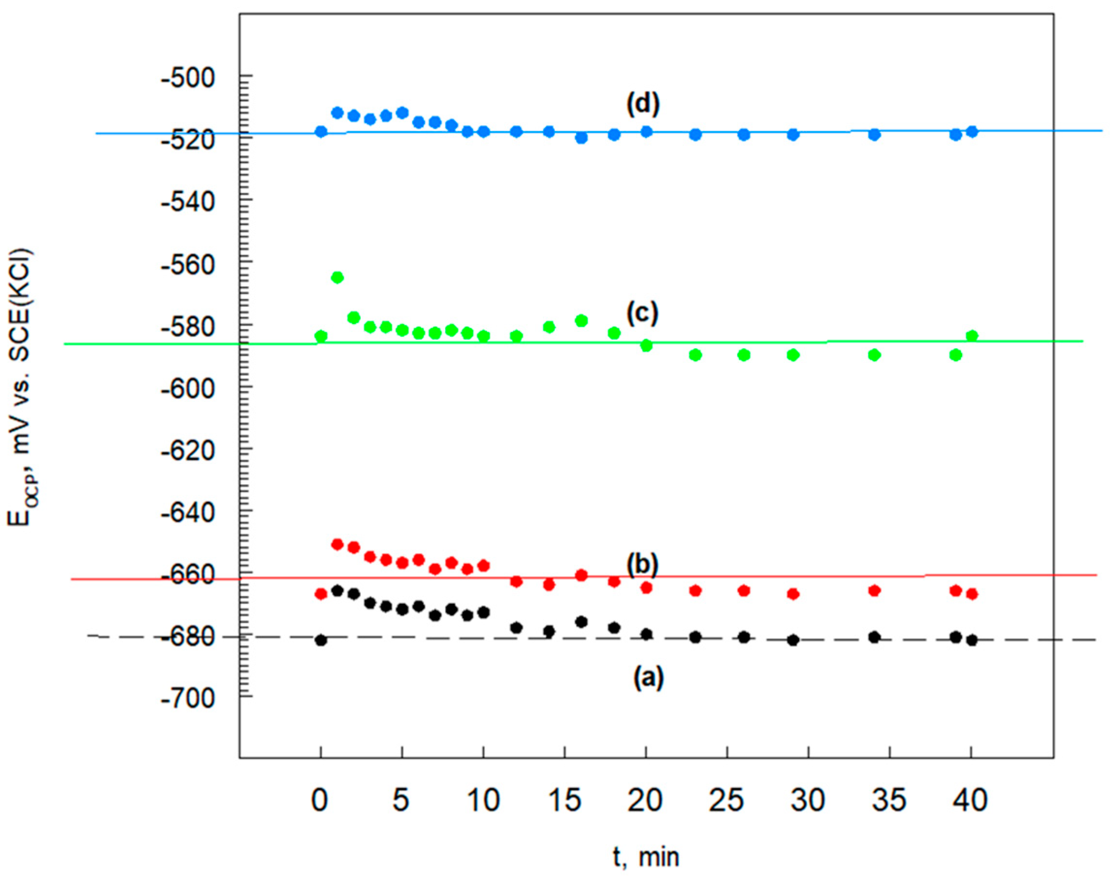
3.6.1. Open Circuit Potential

Open circuit potential (EOCP) measurements are one of the electrochemical methods used to evaluate and estimate the corrosion performance of coating layers. EOCP is a parameter that indicates the thermodynamically tendency of a material to electrochemical oxidation or passivation in a corrosive medium, and the goal of its measurement is to analyses the potential of the specimen without affecting, in any way, the electrochemical reactions on the specimen surface. After a period of immersion, the EOCP usually stabilizes around a stationary value.
Figure 6 shows the evolution of EOCP for the Cr3C2-25(Ni20Cr) cermet coating on the Al7075 substrate before and after exposure in thioacetic acid amide solutions.
The composition of the corrosive environment has a significant impact on the change in the EOCP value (Figure 6). The values of open circuit potential of the Cr3C-25(Ni20Cr) cermet coating on the Al7075 substrate are listed in Table 2.
As the TAA concentration increases, EOCP values shift towards positive values (Table 2). Therefore, it can be assumed that a protective layer with sulfide ions as (MemSn)ads is formed on the surface of the Cr3C2-25(Ni20Cr)/Al7075 coating. The sulfide layer additionally limits the substrate’s contact with the corrosive environment. Moreover, the protective effectiveness of the sulfide layer increases as the thioacetic acid amide concentration increases. Therefore, it can be assumed that an increasingly dense (MemSn)ads layer that adheres well to the surface is formed on the cermet surface.

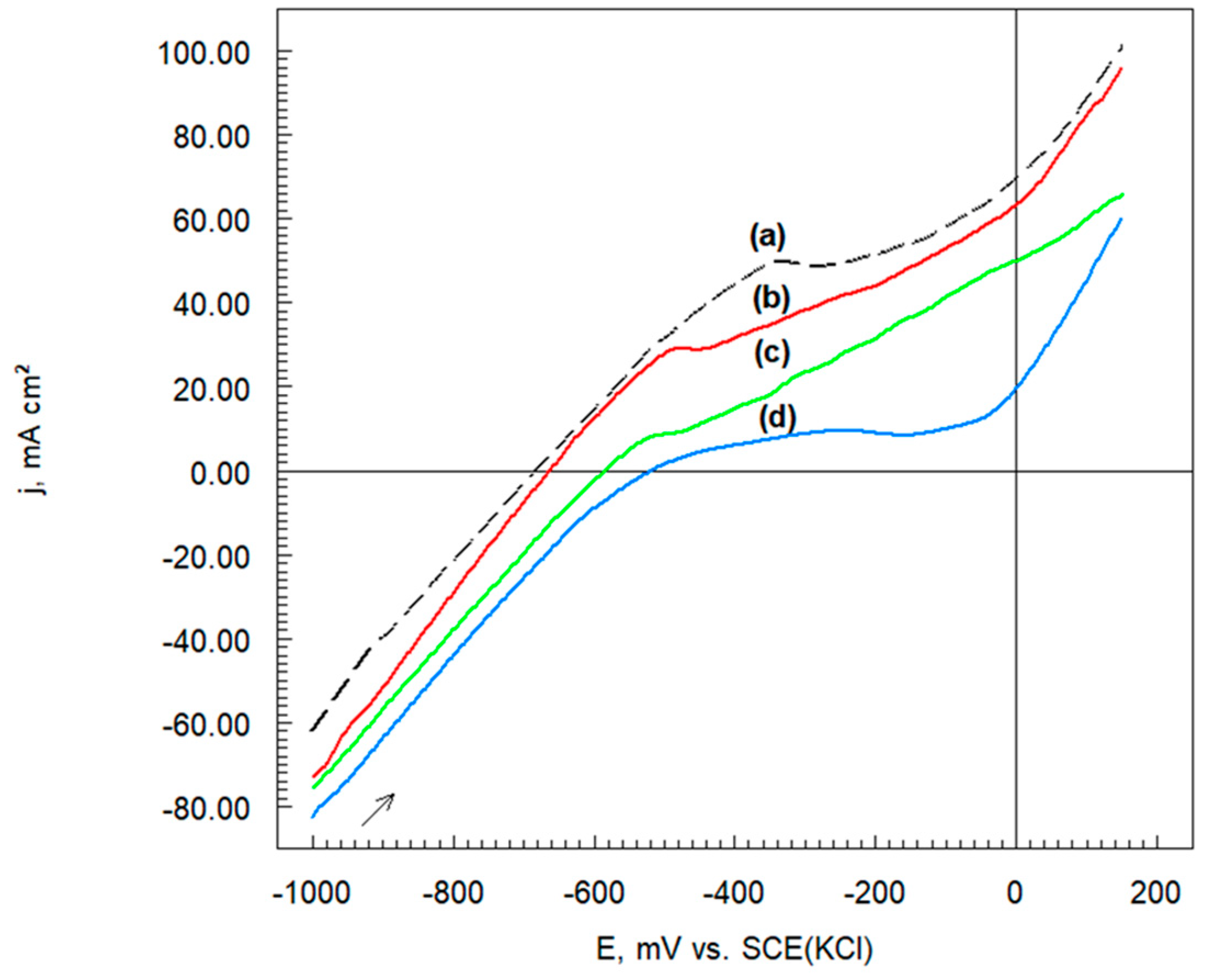
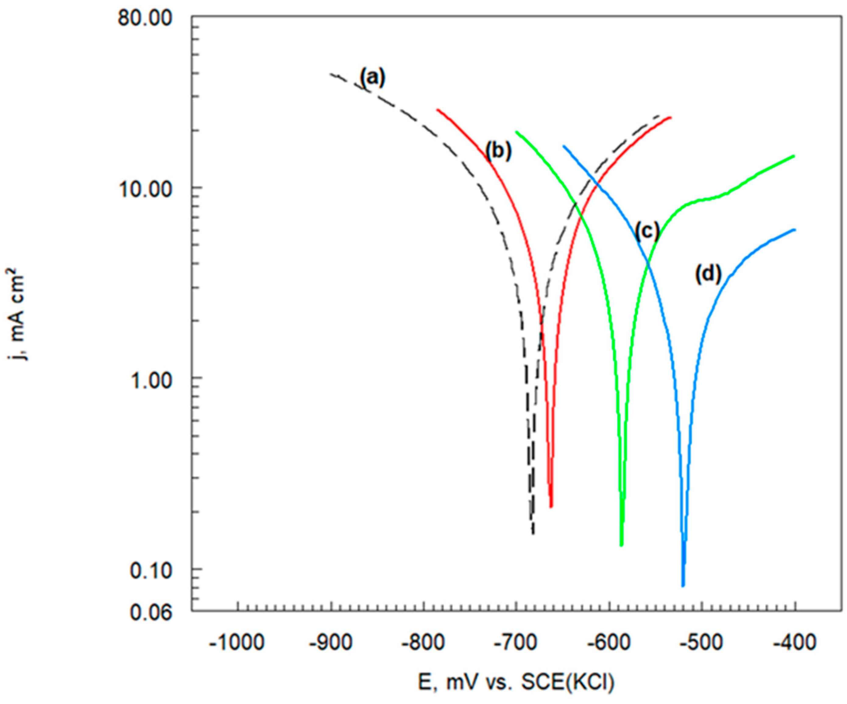
3.6.2. Potentiodynamic Polarization Curves

Potentiodynamic polarization measurements were carried out in order to gain knowledge concerning the kinetics of the cathodic and anodic reactions. The polarization curves of the Cr3C2-25(Ni20Cr)/Al7075 coating before and after exposure in thioacetic acid amide solutions are exhibited in Figure 7.
The process of hydrogen depolarization occurs in the cathode region of the potentiodynamic polarization curve (Figure 7). In the acid corrosive environment, the cathodic branch of curves corresponds to the simplified reduction of hydrogen ions [17,18]:
Me0 + 2 H+ → Me0 + H2 − n e
On the other hand, the anodic reaction was as follows:
Me0 → Mez+ + n e
A systematic increase in the anode current density value is observed with the increase in the electrode potential value (Figure 7). For the Cr3C2-25(Ni20Cr)/Al7075 coating after exposure in the TAA environment, the current density values for the anodic sections of the potentiodynamic polarization curves systematically decreased (Figure 7, curves (b)–(d)). This means that, as a result of the corrosion test, the (MemSn)ads layer was partially destroyed on the surface of the tested samples. Moreover, it seems that the thickest sulfide layer was formed on the Cr3C2-25(Ni20Cr)/Al7075 surface, which was subjected to structure modification in a solution with 0.15 M TAA (Figure 7, curve (d)). It can be assumed that a chloride (MemCln)ads coating could be adsorbed on the exposed cermet surface free from the sulfide layer according to Reactions (1) and (2). The (MemCln)ads can be additionally sealed from the Cr3C2-25(Ni20Cr)/Al7075 coating [17,18]. Therefore, there is a further sharp increase in the density of anode current due to oxidation of the electrode surface (Figure 7, curve (d)).
The electrolyte was not deoxidized, so an oxidation reaction of the coating surface was possible:
m Me0 + n O2 → (MemOn)ads + x e
The surface of the electrode was coated with a porous metal oxide layer, which does not protect the Cr3C2-25(Ni20Cr)/Al7075 surface against further oxidation. Although penetrating pores are not observed in the Cr3C2-25(Ni20Cr)/Al7075 coating as the preferred channel for corrosive ions, non-penetrating pores and cracks on the coating will still initiate localized corrosion. These metastable defects are continuously dissolved and expanded under the action of corrosive media, and eventually become open ion channels, which cause corrosion of the contact substrate of the corrosive media, leading to material failure. In addition, coatings containing Cr are generally considered to have excellent corrosion resistance [19,20]. However, in the Cr3C2-25(Ni20Cr)/Al7075 sample, the Cr content around the NiCr phase is unevenly distributed, and there is a potential difference between the chromium-depleted area and the chromium-rich area [21]. The chromium-depleted area is first attacked and dissolved by active ions. Meanwhile, galvanic corrosion will also occur between the carbide Cr3C2 phase and the NiCr phase. The Cr3C2 phase acts as a cathode and the NiCr phase acts as an anode. A galvanic cell is formed between them, which aggravates the dissolution of the coating. However, the corrosion of cold-sprayed carbide coatings often starts from the boundary between the carbide and the surrounding bonding phase.

3.6.3. Chronoamperometric Curves

The study of current response as a function of time at suitably selected potential is called chronoamperometry (ChA). Figure 8 shows the chronoamperometric curves of the Cr3C2-25(Ni20Cr) cermet coating on the Al7075 substrate after exposure in 0.15 M thioacetic acid amide. The curves were recorded in the solution containing 1.2 M Cl (pH 1.5). However, similar ChA curves were obtained for the remaining Cr3C2-25(Ni20Cr) samples whose surface structure was modified in solutions containing 0.05 M and 0.10 M TAA.
The potentials of the working electrode were selected based on the potentiodynamic polarization curve, i.e., Figure 7, curve (d). However, for the potential of −900 mV vs. SCE(KCl), a H+ ion reduction process (Reaction (6)) took place on the surface of the working electrode (Figure 8, curve (a)). At the beginning, the cathode current density increases. Thus, the H+ ion reduction process is not stable under the experimental conditions. On the other hand, for the potential of −260 mV vs. SCE(KCl) (Figure 8, curve (b)), oxidation of the surface of the Cr3C2-25(Ni20Cr) cermet coating is observed (Reaction (7)). In this case, a systematic increase in the anode current density can be seen during the electrolysis process, as a result of Reaction (7). The oxide coating on the Cr3C2-25(Ni20Cr)/Al7075 surface was sealed due to the adsorption of (Cr2O3)ads and (NiO)ads oxides (Reaction (8)). It can be said that the adsorbed layer of chromium and nickel oxides does not seal the Cr3C2-25(Ni20Cr)/Al7075 surface. However, for a more positive potential of the working electrode, i.e., +100 mV vs. SCE(KCl), the oxidation current density of the Cr3C2-25(Ni20Cr)/Al7075 surface increases with the increase of electrolysis time (Figure 8, curve (c)). This means that, in the acid chloride solution with the participation of TAA, the protective layer adsorbed on the surface of the working electrode is gradually dissolved, as a result of which the cermet coating onto the Al7075 substrate undergoes a corrosion process.

3.7. Corrosion Electrochemical Parameters

Potentiodynamic polarization curves of the Cr3C2-25(Ni20Cr) cermet coatings on the Al7075 substrate (Figure 7) were used to designate the corrosion electrochemical parameters of the tested coatings; see Figure 9.
The corrosion electrochemical parameters of the Cr3C2-25(Ni20Cr) cermet coatings on the Al7075 substrate without and with the addition of thioacetic acid amide are listed in Table 3.
It was found that the values of the corrosion potential (Ecorr) of the tested materials move towards positive values with the increase in concentration of the TAA (Table 3). Therefore, as a result of the increase in the concentration of S2− ions, the corrosion resistance of cermet coatings on the Al7075 substrate increases. At the same time, the lowest value of the corrosion current density was recorded, i.e., jcorr = 3.0 mA cm−2 (Table 2) for the Cr3C2-25(Ni20Cr)—0.15 coating. This means that the best anti-corrosion properties were obtained for the cermet coating in a corrosive environment for the Cr3C2-25(Ni20Cr)-0.15 coating. The slopes, i.e., (-bc) and (ba), of the sections of the Tafel potentiodynamic polarization curves (Figure 9) do not change significantly with the increase of TAA for the tested materials (Table 3). It should be noted that the corrosion mechanism of the Cr3C2-25(Ni20Cr)/Al7075 cermet coatings does not change significantly as the TAA concentration increases.

3.7.1. Polarization Resistance

The polarization resistance (Rp) of the tested materials was determined on the basis of the slopes of the potentiodynamic polarization curves (Table 3) [17,18]. The polarization resistance is described by the following Equations:
R p = B j corr
and
B = b a × b c 2.303 b a + b c
The Rp values of the cermet coatings cold sprayed on the Al7075 alloy are shown in Table 4.
The polarization resistance (Equation (9)) of the Cr3C2-25(Ni20Cr)/Al7075 coatings was determined on the basis of the slope of the Tafel potentiodynamic polarization curves (Table 3). It transpired that, as the TAA concentration increases, the polarization resistance values of the cermet layer on the Al7075 substrate increases. The highest value of polarization resistance, i.e., 14,701 Ω cm2, was recorded for the Cr3C2-25(Ni20Cr)/Al7075 coating after exposure in an environment with 0.15 M TAA. Thus, a thick layer of sulfides was formed on the Cr3C2-25(Ni20Cr)/Al7075 surface according to Reaction (4). However, only in this case, due to the high value of Rp (Table 4), is the exchange of mass and electric charge between the working electrode and the solution significantly hindered.

3.7.2. Corrosion Rate

The corrosion rate (CW) of materials was calculated on the basis of the following Equation:
CW   =   3.268 × ( j c o r r M ) / ( ρ )
where jcorr is the corrosion current density (Table 3), M is the molecular weight of the reacting substrate, and ρ is the density of the material.
However, for the oxidation reaction of the basic component of the cermet coating:
Cr0 − 3 e → Cr3+
Equation (11) can be written as follows:
CW = 56.5 jcorr
The CW values of the Cr3C2-25(Ni20Cr) cermet coatings cold sprayed on the Al7075 alloy are shown in Table 5.
The corrosion rate values of the Cr3C2-25(Ni20Cr)/Al7075 coatings systematically decrease with the increase of TAA concentration (Table 5). It should be added that the corrosion rate value, i.e., 170 mg/year, is also the lowest for the Cr3C2-25(Ni20Cr)-0.15 sample, whose surface structure underwent significant changes as a result of exposure in the solution containing 0.15 M TAA. Thus, the previously edited assumption was confirmed that the best anti-corrosion properties were demonstrated by the Cr3C2-25(Ni20Cr)-0.15 coating. Therefore, the (MemSn)ads layer (Reaction (4)) effectively separates the Cr3C2-25(Ni20Cr)/Al7075 surface from the aggressive corrosive environment.

3.8. Cermet Coating After Corrosion Test

Figure 10 shows the scanning electron microscopy (SEM) image of the surface morphology of the Cr3C2-25(Ni20Cr) cermet coatings on the Al7075 substrate, which was covered with a layer of sulfides after the corrosion test in 1.2 M Cl (pH 1.5). It transpired that the adsorbed (MemSn)ads sulfide layer was partially dissolved by a chemical reaction (Reaction (5)). The Cr3C2-25(Ni20Cr) coating that was formed during exposure in a solution containing 0.05 M TAA was most damaged by corrosion (Figure 10a). As the TAA concentration increased in the solution, less degradation of the surface of the tested samples was observed (Figure 10b,c). Moreover, as a result of (MemSn)ads corrosion, deep pits formed on the surface of the tested samples, through which the aggressive chloride solution penetrated, causing Cr3C2-25(Ni20Cr)/Al7075 corrosion (Figure 10d).
The degree of surface coverage (DS) of cermet coatings was calculated. For this purpose, the following equation was used:
DS = (j0corr − jcorr)/j0corr,
where j0corr is the corrosion current density for the sample without exposure in a solution with TAA and jcorr is the corrosion current density for samples after exposure in the TAA solution (Table 3). The calculation results are summarized in Table 6.
The highest value of the Cr3C2-25(Ni20Cr)/Al7075 surface coverage degree above 0.625 was obtained for the Cr3C2-25(Ni20Cr)-0.15 sample exposed in a solution containing 0.15 M TAA. It can be assumed that, under these experimental conditions, a sufficiently thick (MemSn)ads coating was formed on the cermet surface, which protects the substrate against the aggressive corrosive environment.
In order to increase the degree of surface coverage of the cermet surface by (MemSn)ads, we also attempted to expose Cr3C2-25(Ni20Cr)/Al7075 in the 0.25 M TAA solution. Unfortunately, in this case, the Cr3C2-25(Ni20Cr)/Al7075 surface was covered with an uneven (MemSn)ads layer, which did not adhere well to the cermet surface. Therefore, the (MemSn)ads did not protect the Cr3C2-25(Ni20Cr)/Al7075 surface from contact with the corrosive environment.

4. Conclusions

This paper presents the results of research on the effect of the influence of sulfide (S2) ion concentration on the anti-corrosion properties of a Cr3C2-25(Ni20Cr) coating on a Al7075 substrate. Corrosion tests of sulfide coatings were carried out in a solution containing 1.2 M Cl (pH 1.5). The obtained research results allowed the formulation of the following conclusions:
  • The Cr3C2-25(Ni20Cr) cermet coating was deposited on the Al7075 substrate using the cold-sprayed method. The cermet coating surface was rough and wavy but adhered well to the substrate.
  • The ceramic coatings were chemically modified in a thioacetic acid amide {TAA) environment. The cermet surfaces were covered with a thin, smooth, and well-adhered layer of sulfides (MemSn)ads.
  • As the TAA concentration increases, the microhardness (HV10) of the Cr3C2-25(Ni20Cr)/Al7075 coatings increases slightly.
  • The adsorbed (MemSn)ads layer effectively separates the Cr3C2-25(Ni20Cr)/Al7075 coating surface from contact with the aggressive corrosive environment.
  • The sulfide coatings on the cermet surface were destroyed in the acidic chloride solution. The least destruction of the (MemSn)ads coating was observed for the Cr3C2-25(Ni20Cr)-0.15 sample after exposure in the solution containing 0.15 M TAA.
  • The highest polarization resistance (Rp) and the lowest corrosion rate (CW) values were recorded for the cermet coating after exposure in the solution containing 0.15 M TAA.
  • The (MemSn)ads layer on the Cr3C2-25(Ni20Cr)/Al7075 surface significantly impedes the exchange of mass and electric charge between the electrode and the electrolyte solution.

Funding

These studies had no external funding.

Data Availability Statement

The original contributions presented in this study are included in the article. Further inquiries can be directed to the corresponding author.

Acknowledgments

The author thank Justyna Kańska for their cooperation and participation in the experiments.

Conflicts of Interest

The authors declare no conflicts of interest.

References

  1. Montero-Sistiaga, M.L.; Mertens, R.; Vrancken, B.; Wang, X.; Van Hooreweder, B.; Kruth, J.-P.; Van Humbeeck, J. Changing the alloy composition of Al7075 for better processability by selective laser melting. J. Mater. Process. Technol. 2016, 23B, 437–445. [Google Scholar] [CrossRef]
  2. Rocha, A.M.F.; Bastos, A.C.; Cardoso, J.P.; Rodrigues, F.; Fernandes, C.M.; Soares, F.; Sacramento, J.; Senos, A.M.R.; Ferreira, M.G.S. Corrosion behaviour of WC hardmetals with nickel-based binders. Corros. Sci. 2019, 147, 384–393. [Google Scholar] [CrossRef]
  3. Ang, A.S.M.; Berndt, C.C.; Sesso, M.L.; Anupam, A.S.P.; Kottada, R.S.; Murty, B.S. Plasma-sprayed high entropy alloys: Microstructure and properties of AlCoCrFeNi and MnCoCrFeNi. Metall. Mater. Trans. 2015, 46, 791–800. [Google Scholar] [CrossRef]
  4. Niu, X.; Singh, S.; Garg, A.; Singh, H.; Panda, B.; Peng, X.; Zhang, Q. Review of materials used in laser-aided additive manufacturing processes to produce metallic products. Front. Mech. Eng. 2019, 14, 282–298. [Google Scholar] [CrossRef]
  5. Mazurkiewicz, A.; Smolik, J. Comparative analysis of wear mechanism of different types of forging dies. Arch. Mater. Sci. Eng. 2011, 49, 40–45. [Google Scholar]
  6. Lin, L.; Li, G.-L.; Wang, H.-D.; Kang, J.-J.; Xu, Z.-L.; Wang, H.-J. Structure and wear behavior of NiCr–Cr3C2 coatings sprayed by supersonic plasma spraying and high velocity oxy-fuel technologies. Appl. Surf. Sci. 2015, 356, 383–390. [Google Scholar] [CrossRef]
  7. Bolelli, G.; Berger, L.-M.; Börner, T.; Koivuluoto, H.; Matikainen, V.; Lusvarghi, L.; Lyphout, C.; Markocsan, X.; Nylén, P.; Sassatelli, P.; et al. Sliding and abrasive wear behaviour of HVOF and HVAF-sprayed Cr3C2–NiCr hard metal coatings. Wear 2016, 358–359, 32–50. [Google Scholar] [CrossRef]
  8. Singh, H.; Sidhu, T.S.; Karthikeyan, J.; Kalsi, S.B.S. Development and characterization of Cr3C2–NiCr coated superalloy by novel cold spray process. Mater. Manuf. Process. 2015, 31, 1476–1482. [Google Scholar] [CrossRef]
  9. Vidaller, M.V.; List, A.; Gaertner, F.; Klassen, T.; Dosta, S.; Guilemany, J.M. Single impact bonding of cold sprayed Ti-6Al-4V powders on different substrates. J. Therm. Spray Technol. 2015, 24, 644–658. [Google Scholar] [CrossRef]
  10. Ziemian, C.W.; Wright, W.J.; Cipoletti, D.E. Influence of impact conditions on feedstock deposition behavior of cold-sprayed Fe-based metallic glass. J. Therm. Spray Technol. 2018, 27, 843–856. [Google Scholar] [CrossRef]
  11. Sevillano, F.; Poza, P.; Munez, C.J.; Vezzu, S.; Rech, S.; Trentin, A. Cold-sprayed Ni-Al2O3 coatings for applications in power generation industry. J. Therm. Spray Techn. 2013, 22, 772–782. [Google Scholar] [CrossRef]
  12. Luo, X.-T.; Li, Y.-J.; Li, C.-J. A comparison of cold spray deposition behavior between gas atomized and dendritic porous electrolytic Ni powders under the same spray conditions. Mater. Lett. 2016, 163, 58–60. [Google Scholar] [CrossRef]
  13. Souza, R.C.; Voorwald, H.J.C.; Cioffi, M.O.H. Fatigue strength of HVOF sprayed Cr3C2-25CrNi and WC-10Ni on AISI 4340 steel. Surf. Coat. Technol. 2008, 203, 191–198. [Google Scholar] [CrossRef]
  14. Varis, T.; Suhonen, T.; Calonius, O.; Cuban, J.; Pietola, M. Optimization of HVOF Cr3C2NiCr coating for increased fatigue performance. Surf. Coat. Technol. 2016, 305, 123–131. [Google Scholar] [CrossRef]
  15. Matikainen, V.; Koivuluoto, H.; Vuoristo, P. A study of Cr3C2-based HVOF- and HVAF-sprayed coatings: Abrasion, dry particle erosion and cavitation erosion resistance. Wear 2020, 446–447, 20318. [Google Scholar] [CrossRef]
  16. Luiz, L.A.; de Andrade, J.; Pesqueira, C.M.; Siqueira, I.B.D.A.F.; Sucharski, G.B.; de Sousa, M.J. Corrosion behavior and galvanic corrosion resistance of WC and Cr3C2 cermet coatings in Madeira river water. J. Therm. Spray Technol. 2021, 30, 205–221. [Google Scholar] [CrossRef]
  17. Scendo, M.; Zorawski, W.; Staszewska-Samson, K.; Goral, A. Influence of laser treatment on the corrosion resistance of Cr3C2-25(Ni20Cr) cermet coating. Materials 2021, 14, 4078. [Google Scholar] [CrossRef]
  18. Scendo, M.; Żórawski, W. Corrosion properties of cold-sprayed Cr3C2-25(Ni20Cr) coatings after heat treatment. Materials 2024, 17, 6289. [Google Scholar] [CrossRef]
  19. Bergant, Z.; Trdan, U.; Grum, J. Effect of high-temperature furnace treatment on the microstructure and corrosion behavior of NiCrBSi flame-sprayed coatings. Corros. Sci. 2014, 88, 372–386. [Google Scholar] [CrossRef]
  20. Zheng, Z.B.; Zheng, Y.G.; Sun, W.H.; Wang, J.Q. Erosion–corrosion of HVOF-sprayed Fe-based amorphous metallic coating under impingement by a sand-containing NaCl solution. Corros. Sci. 2013, 76, 337–347. [Google Scholar] [CrossRef]
  21. Sadeghimeresht, E.; Markocsan, N.; Nylén, P.; Björklund, S. Corrosion performance of bi-layer Ni/Cr2C3–NiCr HVAF thermal spray coating. Appl. Surf. Sci. 2016, 369, 470–481. [Google Scholar] [CrossRef]
Figure 1. SEM micrograph: (a) Cr3C2-25(Ni20Cr) powder morphology, (b) X-ray diffraction pattern of powder.
Metals 15 00273 g001
Figure 2. Surface morphology of cold-sprayed cermet coating on the Al7075 substrate: (a) Cr3C2-25(Ni20Cr)/Al7075, (b) X-ray diffraction pattern of as-sprayed coating.
Metals 15 00273 g002
Figure 3. SEM surfaces: (a) Al7075 substrate, (b) Cr3C2-25(Ni20Cr) cermet coating, and (c) cross-section of Cr3C2-25(Ni20Cr) cermet coating on the Al7075 substrate.
Metals 15 00273 g003
Figure 4. SEM surface: (a) Cr3C2-25(Ni20Cr) cermet coating on the Al7075 substrate, (b) cross-section of Cr3C2-25(Ni20Cr)/Al7075 after exposure to an environment of 1.2 M Cl (pH 1.5).
Metals 15 00273 g004
Figure 5. SEM of surface morphology of Cr3C2-25(Ni20Cr) cermet coatings on the Al7075 substrate after exposure in thioacetic acid amide: (a) 0.05 M, (b) 0.10 M, (c) 0.15 M, and (d) cross-section of Cr3C2-25(Ni20Cr)/Al7075 for the 0.15 M TAA.
Metals 15 00273 g005
Figure 6. Evolution of open circuit potential of Cr3C2-25(Ni20Cr) cermet coating on the Al7075 substrate after exposure in (a) 0 M, (b) 0.05 M, (c) 0.10 M, and (d) 0.15 M TAA. The test solution contained 1.2 M Cl (pH 1.5).
Metals 15 00273 g006
Figure 7. Potentiodynamic polarization curves of Cr3C2-25(Ni20Cr) cermet coatings on the Al7075 substrate after exposure in (a) 0 M, (b) 0.05 M, (c) 0.10 M, and (d) 0.15 M TAA. Test solution contained 1.2 M Cl (pH 1.5). dE/dt 1 mV/s.
Metals 15 00273 g007
Figure 8. Chronoamperometric curves of Cr3C2-25(Ni20Cr) cermet coatings on the Al7075 substrate after exposure in 0.15 M TAA. The test solution contained 1.2 M Cl (pH 1.5). Potential values were as follows: (a) −900 mV, (b) −260 mV, (c) +100 mV (average current density values are marked with a dashed line).
Metals 15 00273 g008
Figure 9. Potentiodynamic polarization curves on a semi-logarithmic (Tafel) scale of Cr3C2-25(Ni20Cr) cermet coatings on the Al7075 substrate after exposure in (a) 0 M, (b) 0.05 M, (c) 0.10 M, and (d) 0.15 M TAA. The test solution contained 1.2 M Cl (pH 1.5).
Metals 15 00273 g009
Figure 10. SEM surface of Cr3C2-25(Ni20Cr) cermet coatings on the Al7075 substrate after exposure in (a) 0.05 M, (b) 0.10 M, and (c) 0.15 M TAA. (d) Cross-section of Cr3C2-25(Ni20Cr)/Al7075 for the 0.15 M TAA test solution containing 1.2 M Cl (pH 1.5).
Metals 15 00273 g010
Table 1. Microhardness of Cr3C2-25(Ni20Cr) coatings on the Al7075 substrate after exposure in solutions with thioacetic acid amide.
Sample NameMicrohardness
HV10
Cr3C2-25(Ni20Cr)-0.05358 ± 2
Cr3C2-25(Ni20Cr)-0.10385 ± 1
Cr3C2-25(Ni20Cr)-0.15409 ± 3
Table 2. Values of open circuit potential of Cr3C2-25(Ni20Cr)/Al7075 cermet coating without and after exposure in thioacetic acid amide.
Sample NameEOCP
mV vs. SCE(KCl)
Cr3C2-25(Ni20Cr)−682
Cr3C2-25(Ni20Cr)-0.05−662
Cr3C2-25(Ni20Cr)-0.10−586
Cr3C2-25(Ni20Cr)-0.15−518
Table 3. Corrosion electrochemical parameters of Cr3C2-25(Ni20Cr) coatings on the Al7075 substrate without and after exposure in thioacetic acid amide.
Sample NameEcorrjcorr−bcba
mV vs. SCEmA cm−2mV dec−1
Cr3C2-25(Ni20Cr)−6828.0260270
Cr3C2-25(Ni20Cr)-0.05−6627.0190310
Cr3C2-25(Ni20Cr)-0.10−5865.5180350
Cr3C2-25(Ni20Cr)-0.15−5183.0140370
Table 4. Polarization resistance of Cr3C2-25(Ni20Cr) coatings on the Al7075 substrate without and after exposure in thioacetic acid amide.
Sample NameRp
Ω cm2
Cr3C2-25(Ni20Cr)7189
Cr3C2-25(Ni20Cr)-0.057307
Cr3C2-25(Ni20Cr)-0.109384
Cr3C2-25(Ni20Cr)-0.1514,701
Table 5. Corrosion rate of Cr3C2-25(Ni20Cr) coatings on the Al7075 substrate without and after exposure in thioacetic acid amide.
Sample NameCW
mg/Year
Cr3C2-25(Ni20Cr)452
Cr3C2-25(Ni20Cr)-0.05396
Cr3C2-25(Ni20Cr)-0.10311
Cr3C2-25(Ni20Cr)-0.15170
Table 6. Degree of surface coverage of Cr3C2-25(Ni20Cr) coatings on the Al7075 substrate without and after exposure in thioacetic acid amide.
Sample NameDC
Cr3C2-25(Ni20Cr)-0.050.13
Cr3C2-25(Ni20Cr)-0.100.31
Cr3C2-25(Ni20Cr)-0.150.63
Disclaimer/Publisher’s Note: The statements, opinions and data contained in all publications are solely those of the individual author(s) and contributor(s) and not of MDPI and/or the editor(s). MDPI and/or the editor(s) disclaim responsibility for any injury to people or property resulting from any ideas, methods, instructions or products referred to in the content.

