Abstract
A novel 316L stainless steel Vertex Modified BCC (VM-BCC) lattice unit cell with attractive performance characteristics is developed. Lattice structure, as well as the sandwich panel, are constructed. Numerical simulation is utilized to simulate the quasi-static compression, dynamic compression and blast behavior considering the rate-dependent properties, elastoplastic response and nonlinear contact. Finite element results are validated by comparing with the experimental results. Parametric studies are conducted to gain insight into the effects of loading velocity, equivalent TNT load and explosion distance on the dynamic behavior of the lattice pattern and sandwich panel. Testing results indicate that the proposed 316L stainless steel VM-BCC structure exhibits more superior plateau stress and specific energy absorption (SEA) than those of the BCC or Octet one. The proposed novel lattice will provide reference for improving the protective efficiency in key equipment fields and enhancing overall safety.
1. Introduction
In the fields of building materials and other defense equipment, structural materials with effective protective efficiency and reliable overall safety have an important strategic position. Cellular materials provide a possible way for efficient load-bearing and effective protection. They have attracted widespread attention from researchers owing to their extraordinary mechanical and functional properties in terms of high specific strength and specific stiffness, remarkable energy absorption capacities and attractive multi-functional characteristics [,,]. Generally, cellular materials include stochastic foams and periodic lattice structures []. Among them, owing to the topological designability, customizable performance and function behavior of periodic lattice structures, they have more vigorous vitality and have been widely utilized in fields of load bearing, wave shielding, heat exchange, vibration attenuation and so on [,,,]. Moreover, thanks to the advent and rapid development of the advanced additive manufacturing technology, application scenarios of lattice structures are being further expanded.
In the past few decades, mechanical properties of additively manufactured lattice structures have been extensively studied [,,,,,,,,,,]. Research results indicate that the topology configuration, unit cell size, number of unit cell, strut diameter, relative density and loading condition will all have effects on the mechanical parameters such as equivalent modulus, yield strength and energy absorption of the lattice structures. In addition, additive manufacturing process parameters affect the mechanical properties of structural materials to a great extent, and different combinations of process parameters will result in lattice structures with different mechanical properties []. Random manufacturing defects also inevitably exist in the surface and interior of additively manufactured lattice structures, and the influence of defects on the performance characteristics of lattice materials cannot be neglected [,,]. However, it should be noted that most existing research focuses on the static behavior of lattice materials and studies on their dynamic mechanical properties are still very limited.
Mechanical design is an inexhaustible source of vitality for lattice structures. Traditional design methods mainly include crystal design, hierarchical design, gradient design, node enhanced design, dual phase design and so on [,,]. Researchers have proposed various design methods and constructed rich innovative configurations, striving to continuously improve the specific stiffness and specific strength characteristics of structural materials, and achieve more efficient load-bearing and protection effects. Research results indicate that the Octet lattice [], which is a typical stretch-dominated configuration, is a recognized structural material with superior load-bearing capacity and energy absorption characteristics. When evaluating the stiffness and strength features of new configurations, it is also often used as a performance reference.
In addition to the traditional design methods mentioned above, biomimetic design is a novel design approach. Researchers mimic the structure, function, process, and ecosystem of nature to break through the forefront of science and solve practical engineering problems. For example, researchers can imitate the topological structure of living organisms, such as Chinese sturgeon [], Shell [], Mantis-shrimp [] and so on. However, it should be noted here that, although some work has been carried out, the innovative development and mechanical design of new structural configurations based on biomimetic concepts are still a highly noteworthy direction.
The skeletal system of deep-sea glass sponge is an attractive biological tissue, and innovative configuration design based on it is of great significance. Fernandes et al. [] proposed a new lattice configuration with enhanced strength property and improved deformation stability based on the skeleton of deep-sea glass sponges. Besides, Wang et al. [,] proposed novel MFCC and VM-BCC lattice configurations, and their quasi-static compression mechanical behavior are investigated. Testing results indicate that the VM-BCC lattice surpasses the Octet one comprehensively in the aspects of performance and energy absorption under quasi-static compression. However, it should be noted that only the quasi-static mechanical behavior of the VM-BCC lattice has been studied, and its dynamic and anti-explosion mechanism characteristics are still unclear, which deserves more attention.
The goal of this paper is to investigate the dynamic compression and blast behavior of the 316L stainless steel VM-BCC lattice structure, as well as the sandwich panel through the finite element simulation method, which has been demonstrated to be a powerful tool for evaluating the behavioral characteristics of metal structural materials [,]. Its dynamic behavior is also compared with those of the BCC, CM-BCC, V-BCC and Octet patterns. The rest of this study is organized as follows. Section 2 describes the structural design process. Introduction and verification of the finite element models are given in Section 3. Static and dynamic compression results, blast resistance behavior are illustrated in Section 4 and Section 5, respectively. Finally, key conclusions are drawn in Section 6.
2. Structural Design
In this section, the structural design process, as well as the geometric configurations, are illustrated (see Figure 1). The body-centered cubic (BCC) lattice structure, with a radius of 0.694 mm, is a well-known bending-dominated topology configuration. Based on the most fundamental BCC configuration as the starting point for the topology variation, to increase the loading capacity of the lattice pattern, four vertical and eight horizontal struts are introduced. Through this variation, the varied BCC (V-BCC) lattice unit cell is harvested. The radius of the 12 struts of the cube is 0.5 mm, and the radius of the internal diagonal members is 0.425 mm.
Figure 1.
(a) Geometric configurations of the BCC, CM-BCC, V-BCC, Octet and VM-BCC lattice patterns; (b) VM-BCC design inspired by deep-sea glass sponge.
Inspired by the biomimetic design concept, the Tri-Axis Cubie (TAC) cell is inserted into the Simple Cubic (SC) cell, and 24 diagonal struts are added to the cell to connect the end nodes of the TAC with the corner vertices of the SC cell to design Center Modified BCC (CM-BCC) lattice. The radius of the diagonal struts connecting the part is 0.28 mm, and the radius of the remaining struts is 0.5 mm. The CM-BCC lattice overcomes the weakness of the low stress level of the BCC lattice, and will be described later. Then, inspired by the geometry character of the skeletal system of deep-sea glass sponge (see Figure 1b), connecting joints of the diagonal struts are shifted away from the corner vertices and the Vertex Modified BCC (VM-BCC) lattice is innovated. The radius of the diagonal struts connecting the part is 0.405 mm, and the radius of the remaining struts is 0.5 mm. In order to better demonstrate the advantages of the designed structures, mechanical performance of the most typical stretch-dominated Octet lattice structure with radius of 0.39 mm is also studied in this paper. It should be noted here that the determination of the radius value of the struts is to ensure the constant effective relative density of 0.176. All the unit cell sizes are 7 mm × 7 mm × 7 mm, and the structure sizes are 42 mm × 42 mm × 42 mm.
3. Finite Element Analysis
3.1. Static and Dynamic Compression Computational Model
Commercial finite element software ABAQUS/Explicit (version 2022) is adopted to simulate the quasi-static and dynamic compression behavior of the BCC, CM-BCC, V-BCC, Octet and VM-BCC lattice patterns. As shown in Figure 2a, the lattice pattern is placed between two rigid plates, with the lower one fixed and the upper one applying the load. Herein, U1, U2, U3, UR1, UR2 and UR3 represent the translational and rotational degrees of freedom in three directions, respectively. The displacement load is applied during quasi-static compression, and the velocity load is applied during dynamic condition. Three different loading velocities, i.e., 4.2 m/s, 21 m/s and 42 m/s, are considered. The corresponding strain rates are 100/s, 500/s and 1000/s, respectively. Timoshenko B31 beam element and R3D4 rigid element are adopted to discrete the lattice pattern and plate, respectively. In order to avoid mutual penetration and to match the actual working conditions, a general contact with friction coefficient of 0.2 is defined between the lattice pattern and the rigid plates. Meanwhile, the frictionless self-contact of lattice struts is also defined.
Figure 2.
(a) Front-view schematic of the compression computational model; (b) Uniaxial tensile true stress–strain curve for static compression simulation. Herein, the true stress–strain curve is that of the average of the three dog-bone specimens.
For the parent material, 316L stainless steel is used, and isotropic elastoplastic constitutive model is adopted. The composition of 316L stainless steel includes iron, chromium, nickel, molybdenum, and a small number of other elements. In quasi-static numerical simulation, the stress–strain curve of parent material is obtained from uniaxial tensile test on dog-bone specimens. Herein, the curve in Figure 2b is the true stress–strain curve, and is converted from the nominal tensile stress–strain curve. The true stress–strain curve is that of the average of the three dog-bone specimens, and it can be used as input for simulation []. The material parameters for characterizing dynamic mechanical behavior are set based on the quasi-static curve, and the JC constitutive model is used to consider strain rate effects. In dynamic compression condition, the strain rate effect on mechanical properties of 316L stainless steel material needs to be considered. The Johnson–Cook (JC) model is utilized [], with rate-dependent hardening coefficient and .
3.2. Air Blast Computational Model
The sandwich panel, composed of intermediate lattice patterns and two panels at both ends, is modeled to simulate the mechanical responses under air blast loading. All the constituent materials are 316L stainless steel, and detailed material properties have been described in Section 3.1. As shown in Figure 3, the dimension of the whole lattice sandwich panel is 63 mm × 63 mm × 42 mm. To save computing resources and reduce computation time, 1/4 model is established by applying the symmetric boundary conditions and the other two sides are fixed (see Figure 3). The lattice core is also discreted with the B31 beam element, and the panels are discreted with the S4R shell element with a thickness of 1 mm. To simulate the blast behavior, CONWEP model is adopted [], which is defined as an equivalent TNT load at a certain distance above the center of the target structure. The CONWEP model is a commonly used empirical model for explosion, which can be used for free air field explosion and close range explosion calculations. It considers the compressibility and lightweight characteristics of air, ignoring its stiffness and inertia effects. Therefore, when using it for air explosion analysis, there is no need to model the air dielectric, only the structural model needs to participate in the calculation of explosion response. Meanwhile, to simulate the interaction relationship, the tangential behavior is set as frictionless and the “hard” contact normal behavior is also defined.
Figure 3.
Air blast symmetry model on the lattice sandwich panel.
3.3. Mesh Sensitivity Analysis
Herein, to determine the appropriate element size for simulation, mesh sensitivity analysis has been conducted on the V-BCC lattice pattern. The reaction force , as well as the displacement of the upper panel, is extracted, and the stress and strain can be calculated as
where and are the initial cross-sectional area and height of the lattice pattern, respectively. The initial cross-section area is determined as the square of unit cell size.
Based on the harvested stress–strain curve, Plateau stress and specific energy absorption (SEA) can be calculated as []
where and are the mass and density of the lattice pattern, respectively. Herein, when calculating the plateau stress, the strain is taken as 0.35.
The simulated stress–strain curves of the V-BCC lattice pattern under different element sizes are illustrated in Figure 4a. It can be observed that, as the element size decreases, the performance curve shows a downward trend and tends to stabilize. Correspondingly, all the plateau stress values are summarized in Figure 4b. The plateau stress values are 11.25 MPa, 11.59 MPa, 12.11 MPa, 12.66 MPa, 13.44 MPa, 20.21 MPa and 21.25 MPa for the element sizes of 0.8 mm, 1.0 mm, 1.2 mm, 1.5 mm, 2 mm, 3 mm and 5 mm, respectively. It should be noted here that the experimental plateau stress is 11.27 MPa at a compression strain of 0.35 []. The maximum error is only 2.76% between simulation and experiment when element size is chosen as 1.0 mm. When element size changes from 1 mm to 0.8 mm, the plateau stress value changes little. Finally, the element size is determined as 1.0 mm. In this situation, the number of elements and nodes are 16,542 and 14,491, respectively.
Figure 4.
(a) Effect of element size on the stress–strain curves of the V-BCC lattice pattern; (b) Plateau stress values of the V-BCC lattice pattern at different element sizes.
3.4. Validation of Numerical Results
To validate the accuracy of computational model, simulated compression stress–strain curve as well as deformation state of the V-BCC lattice pattern are compared with those from the experimental test (see Figure 5) []. It can be observed that simulated performance curve match well with the experimental curve. However, the simulated curve is slightly lower, which may be due to the effects of manufacturing defects. The symbol S in Figure 5b is the abbreviation for stress. When compressive strain is 0.2, an apparent 45° localized large deformation can be harvested in simulation. When compressive strain is 0.4, localized deformation occurs in the upper region of the shear band, which can be seen from the simulated state. Similar deformation behavior can also be seen in []. Moreover, the plateau stress values obtained from simulation and experiment also have good consistency (see Figure 4b), further demonstrating the accuracy of the computational model.
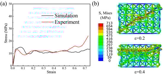
Figure 5.
Comparison of the (a) compression stress–strain curves and the (b) deformation state between simulation and experiment.
4. Static and Dynamic Compression Results
4.1. Static Compressive Behavior
Quasi-static compression stress–strain curves of the BCC, CM-BCC, V-BCC, Octet and VM-BCC lattice patterns are shown in Figure 6a. The curves display typical performance characteristics of cellular materials: linear elastic stage, initial yield stage, platform stress stage and densification stage. The BCC lattice pattern exhibits a steadily improving performance curve as the loading progresses, while apparent oscillations exist in the performance curves of other configurations. The BCC lattice pattern has the lowest performance curve, while the VM-BCC one has the highest performance curve. The corresponding deformation processes of all the five lattice patterns are illustrated in Figure 6c. The BCC lattice pattern exhibits macroscopic overall deformation characteristics, and the V-BCC one exhibits apparent 45° localized large deformation followed by localized deformation in the upper region. The CM-BCC lattice, as well as the Octet one, exhibits a deformation process from top to bottom. However, the VM-BCC lattice exhibits a distinctive deformation behavior. When compression strain is 0.1, deformation is mainly concentrated in the central region. As the structure is compressed further, although the deformation in the central region is still significant, larger deformation exists in the vertical struts at other positions, resulting in a decrease in the load-bearing capacity of the structure. The oscillation of the curve is caused by the large deformation of the vertical struts.
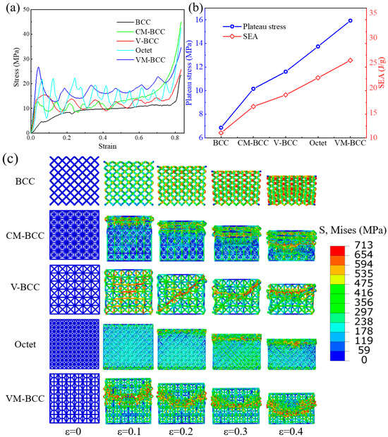
Figure 6.
Quasi-static compression (a) stress–strain curves; (b) plateau stress and SEA; (c) deformation processes of the BCC, CM-BCC, V-BCC, Octet and VM-BCC lattice patterns.
Deformation processes of all the lattice patterns are closely related to the plateau stress and SEA values in Figure 6b. Plateau stress values of the BCC, CM-BCC, V-BCC, Octet and VM-BCC lattice patterns are 6.85 MPa, 10.16 MPa, 11.59 MPa, 13.75 MPa and 15.94 MPa, respectively. SEA values of the BCC, CM-BCC, V-BCC, Octet and VM-BCC lattice patterns are 10.98 J/g, 16.27 J/g, 18.59 J/g, 22.02 J/g and 25.54 J/g, respectively. It can be seen that the VM-BCC lattice possesses the highest plateau stress and SEA values, even higher than the stretch-dominated Octet configuration. When compared to the Octet configuration, the increases in plateau stress and SEA values are 15.93% and 15.99% respectively, demonstrating the superiority of VM-BCC lattice pattern.
4.2. Dynamic Compressive Behavior
Herein, dynamic compression stress–strain relationships as well as deformation features of the BCC, CM-BCC, V-BCC, Octet and VM-BCC lattice patterns are studied. Three different loading velocities, i.e., 4.2 m/s, 21 m/s and 42 m/s, are considered, which correspond to low-speed impact, medium-speed impact and high-speed impact, respectively.
4.2.1. Low-Speed Impact Behavior
In Figure 7a, compression stress–strain curves of the BCC, CM-BCC, V-BCC, Octet and VM-BCC lattice patterns under low-speed impact condition are plotted. The performance curve results are similar to those shown under the quasi-static loading condition, with the only difference being a slight overall improvement. Deformation features of the five lattices are given in Figure 7c. Due to the low loading speed, deformation processes under low-speed impact are also similar to those under quasi-static condition.
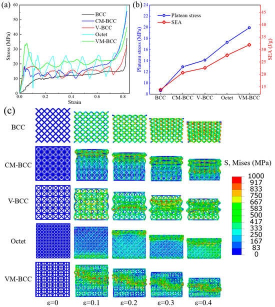
Figure 7.
Low-speed impact compression (a) stress–strain curves; (b) plateau stress and SEA; (c) deformation processes of the BCC, CM-BCC, V-BCC, Octet and VM-BCC lattice patterns.
Then, based on the harvested low-speed impact stress–strain curves, plateau stress and SEA values are calculated in Figure 7b. Low-speed impact plateau stress values of the BCC, CM-BCC, V-BCC, Octet and VM-BCC lattice patterns are 8.62 MPa, 12.90 MPa, 14.11 MPa, 17.29 MPa and 19.91 MPa, respectively. Low-speed impact SEA values of the BCC, CM-BCC, V-BCC, Octet and VM-BCC lattice patterns are 13.81 J/g, 20.66 J/g, 22.61 J/g, 27.71 J/g and 31.90 J/g, respectively. The VM-BCC lattice still possess the highest plateau stress and SEA values under low-speed impact conditions. When the traditional BCC configuration is modified into the VM-BCC one, platform stress and SEA values under low-speed impact can increase by 130.97% and 130.99%, respectively.
4.2.2. Medium-Speed Impact Behavior
Dynamic compression stress–strain curves of the BCC, CM-BCC, V-BCC, Octet and VM-BCC lattice patterns under medium-speed loading condition are illustrated in Figure 8a. Different from those under the quasi-static or low-speed impact condition, further improvement is harvested in the performance curves, and the oscillations of the curves are greater. The stress–strain curves under medium-speed impact show a typical trend: initial peak stress, plateau stress stage and densification stage, and the curves fluctuate significantly throughout the entire compression process. Deformation processes of all the lattice patterns are given in Figure 8c, exhibiting a transition state between low-speed and high-speed impact conditions.
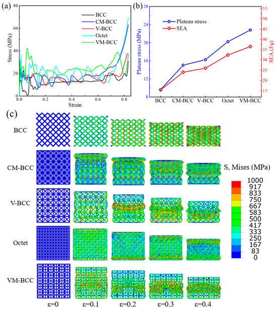
Figure 8.
Medium-speed impact compression (a) stress–strain curves; (b) plateau stress and SEA; (c) deformation processes of the BCC, CM-BCC, V-BCC, Octet and VM-BCC lattice patterns.
The plateau stress and SEA values under medium-speed impact condition are summarized in Figure 8b. Medium-speed impact plateau stress values of the BCC, CM-BCC, V-BCC, Octet and VM-BCC lattice patterns are 9.64 MPa, 15.02 MPa, 16.26 MPa, 20.23 MPa and 22.81 MPa, respectively. Medium-speed impact SEA values of the BCC, CM-BCC, V-BCC, Octet and VM-BCC lattice patterns are 15.45 J/g, 24.06 J/g, 26.04 J/g, 32.41 J/g and 36.54 J/g, respectively. Under the medium-speed impact condition, plateau stress or SEA value of the VM-BCC lattice is 2.37 times that of the BCC configuration and 1.13 times that of the Octet configuration.
4.2.3. High-Speed Impact Behavior
Herein, compression stress–strain curves of the BCC, CM-BCC, V-BCC, Octet and VM-BCC lattice patterns under high-speed impact condition are plotted in Figure 9a. The curves show the typical trend of cellular materials under dynamic loading conditions. Similar to the previous results, the overall performance of VM-BCC structure is in the highest position. Deformation processes of all the lattices under high-speed impact condition are also extracted in Figure 9c. Apparent layer-by-layer deformation process can be seen in the lattices. Take the Octet and VM-BCC configurations as an example. When the compression strain is 0.1, deformation exists in the bottom position of the Octet and VM-BCC lattices. When the compression strain is 0.2, the first and sixth layers of the Octet lattice deform, while the second and fifth layers of the VM-BCC lattice deform. When the structures are compressed further, deformation is transmitted to other layers, ultimately leading to the densification of the whole structure.
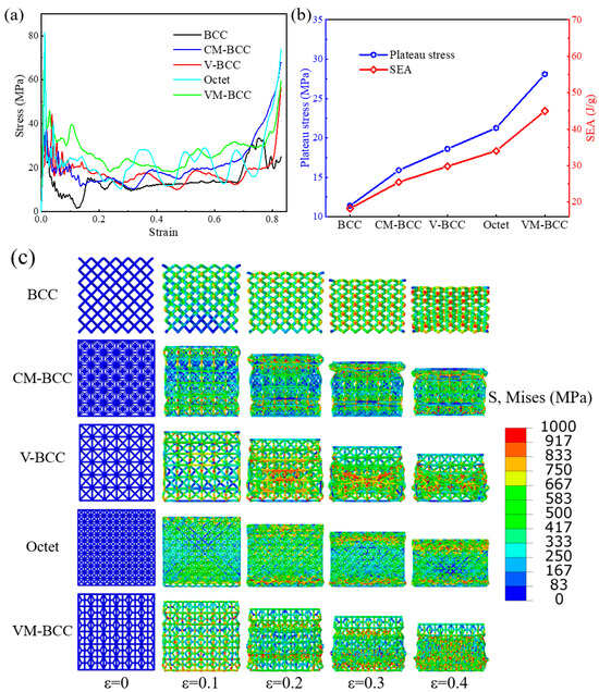
Figure 9.
High-speed impact compression (a) stress–strain curves; (b) plateau stress and SEA; (c) deformation processes of the BCC, CM-BCC, V-BCC, Octet and VM-BCC lattice patterns.
Figure 9b plots the plateau stress and SEA values of all the structures under high-speed impact condition. Plateau stress values of the BCC, CM-BCC, V-BCC, Octet and VM-BCC lattice patterns are 11.39 MPa, 15.90 MPa, 18.61 MPa, 21.27 MPa and 28.08 MPa, respectively. SEA values of the BCC, CM-BCC, V-BCC, Octet and VM-BCC lattice patterns are 18.25 J/g, 25.48 J/g, 29.81 J/g, 34.07 J/g and 44.99 J/g, respectively. Compared with the previous results, it can be found that, under high-speed loading conditions, the structures have better mechanical properties and energy absorption characteristics. Under high-speed impact conditions, the plateau stress or SEA value of the VM-BCC lattice is 2.47 times that of BCC configuration and 1.32 times that of Octet configuration, further demonstrating the superiority of VM-BCC lattice pattern.
4.3. Mechanical Property and Energy Absorption
In this section, in order to compare the mechanical properties and energy absorption characteristics more intuitively, we have summarized the plateau stress and SEA values of all the structures under static and dynamic compression conditions, and relevant results are plotted in Figure 10. It can be observed that, as the loading speed increases, plateau stress and SEA of all the structures show an increasing trend. Compared with the plateau stress or SEA values under quasi-static loading condition, 66.13%, 56.50%, 60.57%, 54.69% and 76.16% increases can be achieved in the BCC, CM-BCC, V-BCC, Octet and VM-BCC lattice patterns respectively under high-speed impact loading conditions, indicating a significant strain rate effect on the performance characteristics. Furthermore, by comparing the plateau stress and SEA values of different structural configurations, we can find that the plateau stress or SEA of VM-BCC lattice is 2.47 times that of the BCC one and 1.32 times that of the Octet one. The intuitive comparison results demonstrate the effective design and superior performance of the VM-BCC lattice, providing guidances for the design of innovative structural configurations with lightweight and high-strength characteristics.
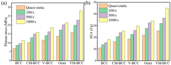
Figure 10.
(a) Plateau stress and (b) SEA of the BCC, CM-BCC, V-BCC, Octet and VM-BCC lattice patterns under different loading velocities.
5. Blast Resistance Behavior
5.1. Effect of Equivalent TNT Load
In Figure 11, blast resistance behavior of the BCC, CM-BCC, V-BCC, Octet and VM-BCC lattice patterns under different equivalent TNT loads are investigated. Herein, three different equivalent TNT loads, i.e., 10 g, 12 g and 14 g, are considered. The blast location is selected at 14 mm above the center of the target structure. It can be observed that the deflection of the back face shows a similar trend, and a larger deflection can be obtained at a larger equivalent TNT load. When the distance from center of plate increases, back face deflection decreases. When focusing on the deflection of back face in different configurations, it can be found that the maximum deflection exists in the back face of the VM-BCC configuration, and the minimum deflection exists in the back face of the BCC one. As the distance from the center of plate increases, deflection in the back face of the VM-BCC configuration shows a rapid downward trend, while the downward trend of deflection in the back face of the other configurations is relatively moderate.
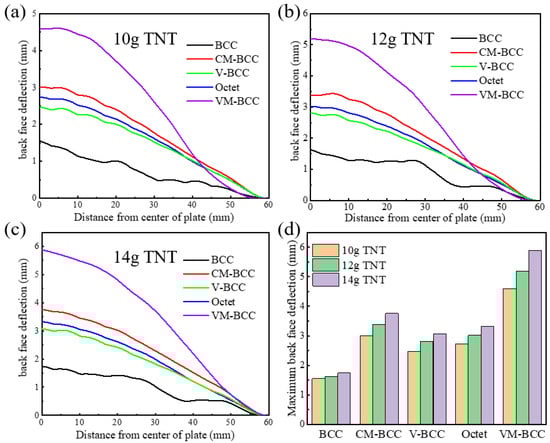
Figure 11.
Back face deflection curves of the BCC, CM-BCC, V-BCC, Octet and VM-BCC lattice patterns at (a) 10 g; (b) 12 g; (c) 14 g equivalent TNT loads. (d) Maximum back face deflection values at different equivalent TNT loads.
Based on the harvested back face deflection curves, maximum back face deflection values at different equivalent TNT loads are summarized in Figure 11d. When the equivalent TNT load is 10 g, the maximum back face deflection for the BCC, CM-BCC, V-BCC, Octet and VM-BCC lattice patterns are 1.55 mm, 3.01 mm, 2.47 mm, 2.74 mm and 4.60 mm, respectively. When the equivalent TNT load is 12 g, the maximum back face deflection for the BCC, CM-BCC, V-BCC, Octet and VM-BCC lattice patterns are 1.62 mm, 3.37 mm, 2.81 mm, 3.02 mm and 5.19 mm, respectively. When the equivalent TNT load is 14 g, the maximum back face deflection for the BCC, CM-BCC, V-BCC, Octet and VM-BCC lattice patterns are 1.74 mm, 3.76 mm, 3.07 mm, 3.32 mm and 5.88 mm, respectively.
5.2. Effect of Explosion Distance
Figure 12a–c illustrates the back face deflection curves of the BCC, CM-BCC, V-BCC, Octet and VM-BCC lattice patterns under different explosion distances. Herein, three different explosion distances, i.e., 14 mm, 18 mm and 22 mm, are considered. The equivalent TNT load remains unchanged at 10 g. It can be observed that the deflection of the back face shows a decreasing trend as the explosion distance increases. Similar to those shown in Section 5.1, the maximum deflection exists in the back face of the VM-BCC configuration, and the minimum deflection exists in the back face of the BCC one.
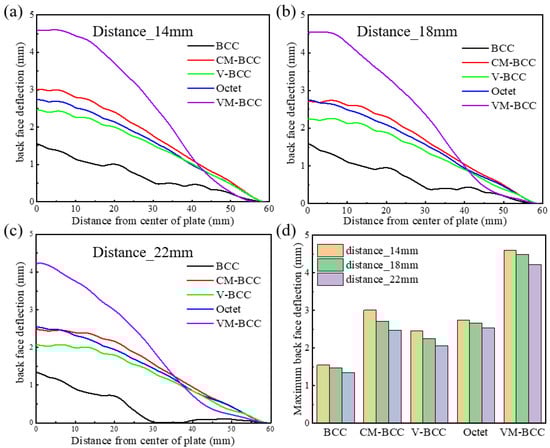
Figure 12.
Back face deflection curves of the BCC, CM-BCC, V-BCC, Octet and VM-BCC lattice patterns at (a) 14 mm; (b) 18 mm; (c) 22 mm explosion distances. (d) Maximum back face deflection values at different explosion distances.
Then, maximum back face deflection values at different explosion distances are plotted in Figure 12d. When the explosion distance is 14 mm, the maximum back face deflection for the BCC, CM-BCC, V-BCC, Octet and VM-BCC lattice patterns are 1.55 mm, 3.01 mm, 2.47 mm, 2.74 mm and 4.60 mm, respectively. When the explosion distance is 18 mm, the maximum back face deflection for the BCC, CM-BCC, V-BCC, Octet and VM-BCC lattice patterns are 1.48 mm, 2.71 mm, 2.25 mm, 2.66 mm and 4.49 mm, respectively. When the explosion distance is 22 mm, the maximum back face deflection for the BCC, CM-BCC, V-BCC, Octet and VM-BCC lattice patterns are 1.34 mm, 2.48 mm, 2.07 mm, 2.54 mm and 4.23 mm, respectively.
In order to better analyze the blast resistance behavior of the five structures, stress distribution characteristics of their final state (see Figure 13) are extracted during the explosion process. Herein, take the 10 g equivalent TNT load and 14 mm explosion distance as an example. It can be seen that stress of the BCC internal structure as well as the back face are the lowest, while that of the VM-BCC internal structure as well as the back face are the highest, and the stress is mainly concentrated below the explosion location of TNT. The stress distribution results are consistent with the distribution rule of the maximum back face deflection in Section 5.1 and Section 5.2, which is also the direct cause of its distribution characteristics.
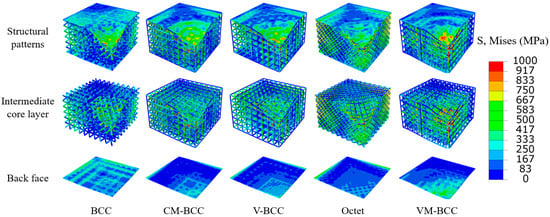
Figure 13.
Stress distribution characteristics of the structural patterns, intermediate core layer and back face under 10 g equivalent TNT load and 14 mm explosion distance.
6. Conclusions
Inspired by the geometry character of the skeletal system of deep-sea glass sponge, a novel 316L stainless steel Vertex Modified BCC (VM-BCC) lattice is proposed, and its quasi-static compression, dynamic compression and air blast behavior are investigated and compared with those of the traditional body-centered cubic (BCC), modified configurations and the stretch-dominated Octet one. Finite element results are validated through experimental tests. Parametric studies are conducted to study the effects of compressive loading velocity, equivalent TNT load and explosion distance on the mechanical properties and deformation behavior of the lattice specimens. The key conclusions are summarized as
- (1)
- Under quasi-static loading condition, plateau stress and SEA of the VM-BCC lattice is higher than that of the BCC or Octet one. Even compared with the typical stretch-dominated Octet configuration, 15.93% and 15.99% increases in plateau stress and SEA in the VM-BCC pattern can also be harvested, respectively.
- (2)
- As the loading speed increases, plateau stress and SEA of all the structures show an increasing trend, indicating a significant strain rate effect on the performance characteristics. Under high-speed loading conditions, the plateau stress or SEA of VM-BCC lattice is 2.47 times that of BCC one and 1.32 times that of Octet one.
- (3)
- Under air blast loading conditions, a larger back face deflection can be obtained at a larger equivalent TNT load and a smaller explosion distance. The maximum deflection exists in the back face of the VM-BCC configuration, and the minimum deflection exists in the back face of the BCC one.
Overall, this study proposes a novel Vertex Modified BCC (VM-BCC) lattice, and its superior quasi-static compression, dynamic compression and air blast behavior have been demonstrated. We think, that the proposed VM-BCC lattice will offer inspiration for the design of protective structural materials in the area of building materials, and also provide reference for improving the protective efficiency in key equipment fields and enhancing the overall safety.
Author Contributions
Conceptualization, F.Z. and X.C.; methodology, F.Z. and Z.X.; software, F.Z.; validation, Z.X.; investigation, F.Z. and X.C.; writing—original draft preparation, F.Z.; supervision, Z.X. and X.C.; funding acquisition, X.C. All authors have read and agreed to the published version of the manuscript.
Funding
The authors would like to thank the support from the National Natural Science Foundation of China (No. 12302482), the Fundamental Research Funds for the Central Universities (WUT: 233114001), the support from Wuhan Natural Science Foundation Exploration Program (Morning Light Program), and the support from General Program of Hubei Provincial Natural Science Foundation. The authors also thank the funding from the Open Foundation of Hubei Key Laboratory of Engineering Structural Analysis and Safety Assessment in Huazhong University of Science and Technology.
Data Availability Statement
The original contributions presented in this study are included in the article. Further inquiries can be directed to the corresponding author.
Conflicts of Interest
The authors declare no conflicts of interest.
References
- Gibson, L.J.; Ashby, M.F. Cellular Solids: Structure and Properties; Cambridge University Press: Cambridge, UK, 1997. [Google Scholar]
- Ashby, M.F. Metal Foams—A Design Guide; Butterworth-Heinemann: Oxford, UK, 2000. [Google Scholar]
- Ashby, M.F.; Shercliff, H.; Cebon, D. Materials: Engineering, Science, Processing and Design; Cambridge University Press: Cambridge, UK, 2007. [Google Scholar]
- Mazur, M.; Leary, M.; McMillan, M.; Sun, S.; Shidid, D.; Brandt, M. Mechanical properties of Ti6Al4V and AlSi12Mg lattice structures manufactured by Selective Laser Melting (SLM). In Laser Additive Manufacturing; Woodhead Publishing: Cambridge, UK, 2017; pp. 119–161. [Google Scholar]
- Banhart, J. Manufacture, characterisation and application of cellular metals and metal foams. Prog. Mater. Sci. 2001, 46, 559–632. [Google Scholar] [CrossRef]
- Deshpande, V.; Ashby, M.; Fleck, N. Foam topology: Bending versus stretching dominated architectures. Acta Mater. 2001, 49, 1035–1040. [Google Scholar] [CrossRef]
- Lu, T.; Valdevit, L.; Evans, A. Active cooling by metallic sandwich structures with periodic cores. Prog. Mater. Sci. 2005, 50, 789–815. [Google Scholar] [CrossRef]
- Gibson, L.J.; Ashby, M.F.; Harley, B.A. Cellular Materials in Nature and Medicine; Cambridge University Press: Cambridge, UK, 2010. [Google Scholar]
- Babaee, S.; Jahromi, B.H.; Ajdari, A.; Nayeb-Hashemi, H.; Vaziri, A. Mechanical properties of open-cell rhombic dodecahedron cellular structures. Acta Mater. 2012, 60, 2873–2885. [Google Scholar] [CrossRef]
- Hedayati, R.; Sadighi, M.; Mohammadi-Aghdam, M.; Hosseini-Toudeshky, H. Comparison of elastic properties of open-cell metallic biomaterials with different unit cell types. J. Biomed. Mater. Res. B Appl. Biomater. 2017, 106, 386–398. [Google Scholar] [CrossRef]
- Maskery, I.; Aboulkhair, N.T.; Aremu, A.O.; Tuck, C.J.; Ashcroft, I.A.; Wildman, R.D.; Hague, R.J.M. A mechanical property evaluation of graded density Al-Si10-Mg lattice structures manufactured by selective laser melting. Mater. Sci. Eng. A 2016, 670, 264–274. [Google Scholar] [CrossRef]
- Smith, M.; Guan, Z.; Cantwell, W.J. Finite element modelling of the compressive response of lattice structures manufactured using the selective laser melting technique. Int. J. Mech. Sci. 2013, 67, 28–41. [Google Scholar] [CrossRef]
- Ozdemir, Z.; Hernandez-Nava, E.; Tyas, A.; Warren, J.A.; Fay, S.D.; Goodall, R.; Todd, I.; Askes, H. Energy absorption in lattice structures in dynamics: Experiments. Int. J. Impact Eng. 2016, 89, 49–61. [Google Scholar] [CrossRef]
- Xiao, L.; Song, W.; Wang, C.; Tang, H.; Fan, Q.; Liu, N.; Wang, J. Mechanical properties of open-cell rhombic dodecahedron titanium alloy lattice structure manufactured using electron beam melting under dynamic loading. Int. J. Impact Eng. 2017, 100, 75–89. [Google Scholar] [CrossRef]
- Xiao, L.; Song, W. Additively-manufactured functionally graded Ti-6Al-4V lattice structures with high strength under static and dynamic loading: Experiments. Int. J. Impact Eng. 2018, 111, 255–272. [Google Scholar] [CrossRef]
- Hedayati, R.; Hosseini-Toudeshky, H.; Sadighi, M.; Mohammadi-Aghdam, M.; Zadpoor, A.A. Computational prediction of the fatigue behavior of additively manufactured porous metallic biomaterials. Int. J. Fatigue 2016, 84, 67–79. [Google Scholar] [CrossRef]
- Leuders, S.; Thone, M.; Riemer, A.; Niendorf, T.; Troster, T.; Richard, H.A.; Maier, H.J. On the mechanical behaviour of titanium alloy TiAl6V4 manufactured by selective laser melting: Fatigue resistance and crack growth performance. Int. J. Fatigue 2013, 48, 300–307. [Google Scholar] [CrossRef]
- Horn, T.J.; Harrysson, O.L.A.; Marcellin-Little, D.J.; West, H.A.; Lascelles, B.D.X.; Aman, R. Flexural properties of Ti6Al4V rhombic dodecahedron open cellular structures fabricated with electron beam melting. Addit. Manuf. 2014, 1–4, 2–11. [Google Scholar] [CrossRef]
- Gümrük, R.; Mines, R.A.W.; Karadeniz, S. Static mechanical behaviours of stainless steel micro-lattice structures under different loading conditions. Mater. Sci. Eng. A 2013, 586, 392–406. [Google Scholar] [CrossRef]
- Miao, X.; Hu, J.; Xu, Y.; Su, J.; Jing, Y. Review on mechanical properties of metal lattice structures. Compos. Struct. 2024, 342, 118267. [Google Scholar] [CrossRef]
- Yang, H.; Cao, X.; Zhang, Y.; Li, Y. 3D-printed bioinspired cage lattices with defect-tolerant mechanical properties. Addit. Manuf. 2024, 82, 104036. [Google Scholar] [CrossRef]
- Cao, X.; Yang, H.; Ren, X.; Wu, W.; Xi, L.; Li, Y.; Fang, D. Mechanical performance and defect analysis of the imperfect micro smooth gyroid cylinder shell structure. Compos. Struct. 2021, 273, 114320. [Google Scholar] [CrossRef]
- Cao, X.; Jiang, Y.; Zhao, T.; Wang, P.; Wang, Y.; Chen, Z.; Li, Y.; Xiao, D.; Fang, D. Compression experiment and numerical evaluation on mechanical responses of the lattice structures with stochastic geometric defects originated from additive-manufacturing. Compos. Part B Eng. 2020, 194, 108030. [Google Scholar] [CrossRef]
- Wu, W.; Xia, R.; Qian, G.; Liu, Z.; Razavi, N.; Berto, F.; Gao, H. Mechanostructures: Rational mechanical design; fabrication; performance evaluation, and industrial application of advanced structures. Prog. Mater. Sci. 2023, 131, 101021. [Google Scholar] [CrossRef]
- Gao, J.; Cao, X.; Xiao, M.; Yang, Z.; Zhou, X.; Li, Y.; Gao, L.; Yan, W.; Rabczuk, T.; Mai, Y. Rational designs of mechanical metamaterials: Formulations, architectures, tessellations and prospects. Mater. Sci. Eng. R Rep. 2023, 156, 100755. [Google Scholar] [CrossRef]
- Chen, P.; Han, Y.; Lu, J. Design and Optimization of Lattice Structures: A Review. Appl. Sci. 2020, 10, 6374. [Google Scholar] [CrossRef]
- Weeks, J.; Gandhi, V.; Ravichandran, G. Shock compression behavior of stainless steel 316L octet-truss lattice structures. Int. J. Impact Eng. 2022, 169, 104324. [Google Scholar] [CrossRef]
- Zheng, Y.; Li, X.; Liu, P.; Chen, Y.; Guo, C. The Armor of the Chinese Sturgeon: A Study of the Microstructure and Mechanical Properties of the Ventral Bony Plates. Micromachines 2023, 14, 256. [Google Scholar] [CrossRef]
- Zhang, X.; Wu, K.; Ni, Y.; He, L. Anomalous inapplicability of nacre-like architectures as impact-resistant templates in a wide range of impact velocities. Nat. Commun. 2022, 13, 7719. [Google Scholar] [CrossRef]
- Weaver, J.C.; Milliron, G.W.; Miserez, A.; Lutterodt, K.E.; Herrera, S.; Gallana, I.; Mershon, W.J.; Swanson, B.; Zavattieri, P.; DiMasi, E.; et al. The Stomatopod Dactyl Club: A Formidable Damage-Tolerant Biological Hammer. Science 2012, 336, 1275–1280. [Google Scholar] [CrossRef] [PubMed]
- Fernandes, M.C.; Aizenberg, J.; Weaver, J.C.; Bertoldi, K. Mechanically robust lattices inspired by deep-sea glass sponges. Nat. Mater. 2020, 20, 237–241. [Google Scholar] [CrossRef] [PubMed]
- Wang, P.; Yang, F.; Li, P.; Zheng, B.; Fan, H. Design and additive manufacturing of a modified face-centered cubic lattice with enhanced energy absorption capability. Extrem. Mech. Lett. 2021, 47, 101358. [Google Scholar] [CrossRef]
- Wang, P.; Yang, F.; Li, P.; Zhang, W.; Lu, G.; Fan, H. Bio-inspired vertex modified lattice with enhanced mechanical properties. Int. J. Mech. Sci. 2023, 244, 108081. [Google Scholar] [CrossRef]
- Churyumov, A.Y.; Kazakova, A.A.; Pozdniakov, A.V.; Churyumova, T.A.; Prosviryakov, A.S. Investigation of Hot Deformation Behavior and Microstructure Evolution of Lightweight Fe-35Mn-10Al-1C Steel. Metals 2022, 12, 831. [Google Scholar] [CrossRef]
- Khomutov, M.G.; Pozdniakov, A.V.; Churyumov, A.Y.; Barkov, R.Y.; Solonin, A.N.; Glavatskikh, M.V. Flow Stress Modelling and 3D Processing Maps of Al4.5Zn4.5Mg1Cu0.12Zr Alloy with Different Scandium Contents. Appl. Sci. 2021, 11, 4587. [Google Scholar] [CrossRef]
- Du, M.; Niu, H.; Wang, K.; Du, X.; Ma, B.; Yan, G.; Huang, Z.; Cao, X.; Lin, Y. Response of Topological Soliton lattice structures subjected to dynamic compression and blast loading. Thin-Walled Struct. 2023, 188, 110858. [Google Scholar] [CrossRef]
Disclaimer/Publisher’s Note: The statements, opinions and data contained in all publications are solely those of the individual author(s) and contributor(s) and not of MDPI and/or the editor(s). MDPI and/or the editor(s) disclaim responsibility for any injury to people or property resulting from any ideas, methods, instructions or products referred to in the content. |
© 2025 by the authors. Licensee MDPI, Basel, Switzerland. This article is an open access article distributed under the terms and conditions of the Creative Commons Attribution (CC BY) license (https://creativecommons.org/licenses/by/4.0/).