Abstract
End plates are important multi-functional components of the fuel cells. They provide structural support and are responsible for channeling the reactant gases, by-product water, and fuel cell coolant in and out of the fuel cell stack. Among various materials used for end plates, aluminum alloy is used due to its high strength and low density. But its corrosion resistance depends on the environment. The operating fuel cell conditions may cause the fuel cell coolant to become more acidic or basic in nature and thus can lead to corrosion of end plates. In this work, a common die-cast aluminum alloy, AlSi10Mg(Fe), is used for end plates, and its corrosion behavior in direct contact with the fuel cell coolant is analyzed. The electrochemical characterization of uncoated and anodized aluminum alloy was achieved using electrochemical impedance spectroscopy, potentiodynamic and potentiostatic polarization tests at room temperature and at the operating temperature of the fuel cell at 80 °C. It was found that for the uncoated aluminum alloy, the corrosion sensitivity is slightly increased when the temperature increases. In comparison, the anodized aluminum alloy reveals a decrease in corrosion sensitivity after 100 h of potentiostatic control, indicating an ongoing passivation of the surface due to the formation of aluminum oxides/hydroxides and aluminum alcohol corrosion products.
1. Introduction
With an increase in global demand for energy and depletion of fossil fuels, fuel cells are promising as a renewable source of energy with lower emissions of harmful products than other traditional energy conversion technologies. A fuel cell is an electrochemical device that converts the chemical energy of fuel into electrical energy [1]. Among various types of fuel cells, proton exchange membrane fuel cells (PEMFCs) have received significant attention in the transportation sector due to their high-power density, low operating temperatures, and quick start-up [2]. A PEMFC consists of a polymer membrane sandwiched between an anode and a cathode. At the anode, the hydrogen oxidation reaction takes place, and at the cathode, the oxygen reduction reaction takes place. The operating temperature of a PEMFC is between 40 and 120 °C [3]. A PEMFC stack consists of a membrane electrode assembly (MEA), which is a multilayer assembly of anode, cathode, and membrane. Other components of the stack are bipolar plates, current collectors, seals, and end plates [4].
An important component of the fuel cell is the endplates that are located on each side of the fuel cell stack. End plates are important for ensuring an even pressure distribution and good sealing between the components of the stack. They have inlet and outlet channels for the supply and removal of the reactant gases and by-product water [5,6]. They also have supply channels for the liquid coolant, which is necessary to maintain a uniform temperature of the stack. Moreover, during the operation of the fuel cell, the endplate is also influenced by the electric field that arises between the stack components and can promote a corrosive attack in the area of the coolant supply. Thus, the end plate material must have good mechanical properties to withstand the operating temperature and pressure, and in addition, it should also ensure high electrochemical stability in the fuel cell environment. End plates are commonly made of titanium, stainless steel, and aluminum alloys. Titanium alloys have good corrosion-resistant properties and mechanical strength but are not widely used due to their high costs [6,7]. End plates made of stainless steel are comparatively cheaper. However, in case of corrosion, the iron contamination leads to significant degradation of the membrane and loss of fuel cell performance [8]. Aluminum alloy end plates are another alternative because of their high strength, lower density, and ease of manufacture [7]. However, the corrosion resistance of aluminum alloys highly depends on the pH value of the environment and the passive oxide formed. Thus, the supplied media, such as the liquid coolant, can have a corrosive effect on the aluminum alloy end plate if they become acidic or basic under operating conditions. To improve the corrosion resistance of aluminum alloy, surface treatments like electrolytic anodization are considered, which form an amorphous oxide layer up to a thickness of a few micrometers and protect the surface by acting as a barrier [9,10].
Pozio et al. [8] studied the influence of stainless-steel end plates as a source of iron contamination and compared it with an aluminum alloy end plate. They showed a correlation between iron contamination of Nafion membrane degradation measured by massive loss of fluoride ions. Their results show that when aluminum alloy end plates are used, the iron contamination is very low and, as such, the polymer membrane degradation is lower. Fu et al. [11] compared the corrosion behavior of anodized aluminum alloy end plates that were prepared by two different anodization conditions (at constant current density and at constant voltage) and sealing methods (in boiling water and in epoxy resin) and pointed out their suitability as end plate material. Their electrochemical results showed that the anodized aluminum alloy sealed with epoxy resin at constant current density has better corrosion resistance in simulated PEMFC environments (0.5 M H2SO4 + 5 ppm F−). Except for these articles, almost no other work has been published that discusses the corrosion of end plates in the fuel cells.
With this work, our aim is to understand the corrosion effect of fuel cell coolant in direct contact with the end plates in PEMFC conditions. For this, we chose a commonly used die-cast aluminum alloy, AlSi10Mg(Fe), for manufacturing the end plates. This was because the pressure die-casting process allows ease of production for complex structural components with good dimensional accuracy and surface quality at low cost and in large quantities. Uncoated and anodized AlSi10Mg(Fe) end plates were electrochemically characterized in the presence of fuel cell coolant Glysantin®. Various electrochemical characterization techniques such as electrochemical impedance spectroscopy, potentiodynamic and potentiostatic polarization, and surface analysis by scanning electron microscopy (SEM) were performed at room temperature and at 80 °C (PEMFC operating temperature) to characterize the corrosion properties of aluminum alloy end plates.
2. Materials and Methods
For this study, end plates of the aluminum alloy AlSi10Mg(Fe) with the chemical composition given in Table 1 were manufactured by a pressure die-casting process at Handtmann Leichtmetallgießerei Annaberg GmbH, Annaberg-Buchholz, Germany. The connections through which coolant flows were made of the aluminum alloy AlSi1MgCuMn and attached to the end plate by a friction stir welding process. The entire end plate, including the connections, was then completely anodized under industrial conditions. The anodization was performed in sulfuric acid by applying direct current. The average thickness of the anodized coating was determined to be d ~ < 5 µm.

Table 1.
Chemical composition of aluminum alloy AlSi10Mg(Fe) (wt. %).
For electrochemical characterization measurements, samples were cut from the uncoated and anodized end plates according to the requirement. One side of the anodized samples was grinded with #200 grit SiC abrasive paper to remove the passive oxide layer, ensuring electrical contact to the used test setup. The other side of the samples was left in an unprepared state in order to analyze the corrosion behavior against the coolant. Finally, before conducting the electrochemical measurements, all the samples were rinsed with ethanol and distilled water and dried.
The electrochemical studies were conducted on both uncoated and anodized end plate samples using a Gamry Instruments Interface 1010 B potentiostat (Warminster, PA, USA). A three-electrode cell setup was used with an end plate sample as the working electrode, a platinum mesh as the counter electrode, and an Ag/AgCl electrode as the reference electrode. Corrosion measurements were performed in ethylene glycol-based coolant Glysantin FC G 20-00/50 (BASF SE, Ludwigshafen, Germany) at room temperature and at 80 °C to simulate PEMFC conditions during rest periods and during operation. The coolant is characterized by low conductivity with σ = 1.6 µS/cm at room temperature and σ = 2.2 µS/cm at 80 °C and a slightly acidic pH value (pH = 5.5), which means that a low corrosion attack is expected.
In this study, the electrode surface area that was exposed to electrolyte was 0.79 cm2. Prior to the measurements, the open circuit potential (OCP) was measured for 30 min to achieve steady state conditions. Electrochemical impedance spectroscopy (EIS) was carried out in a frequency range of 0.01 Hz to 20 kHz with a sinusoidal potential amplitude of 10 mV. The obtained EIS data were fitted to an equivalent circuit and analyzed using the Gamry Echem Analyst software (Version 6.3). For analyzing the electrochemical corrosion performance of the alloy under fuel cell operation conditions, polarization tests up to an anodic potential of 1 V vs. ERef were performed. In detail, potentiodynamic polarization with a scan rate of 0.1 mV/s was conducted in a potential range of −0.2 V vs. EOCP up to 1.0 V vs. ERef, analyzing the active/passive surface characteristics when the potential increases steadily. A final potential of 1.0 V vs. Eref was used to obtain a stable corrosion current density value on the anodic curve. Based on this potential, the parameters of the potentiostatic test were decided. Potentiostatic polarization tests were performed at 1 V vs. Eref for a duration of 100 h, characterizing the corrosion current density at a constant positive overpotential. This would show the influence of applied high potential when the fuel cell is in operating conditions. Similar potentiostatic tests have also been performed by Fu et al. [11] for aluminum alloy end plates in 0.5 M H2SO4 + 5 ppm F− at 26 °C. For ensuring reproducibility, all electrochemical measurements were carried out three times.
Finally, after the electrochemical corrosion tests, the effect of corrosion on the surface of the material was analyzed using scanning electron microscopy (SEM—TESCAN, MIRA 3XMU, Brno, Czech Republic).
3. Results and Discussion
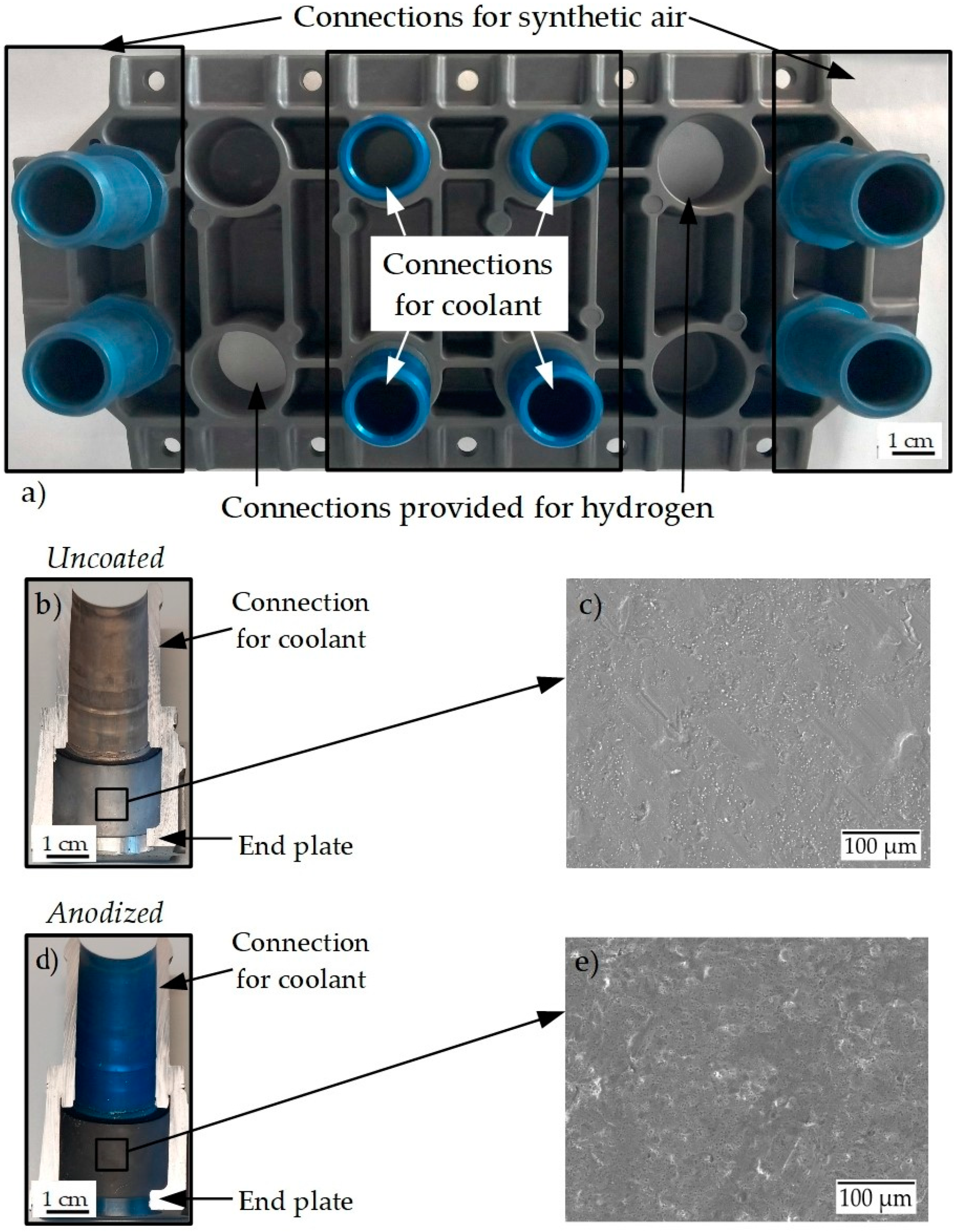
Figure 1a shows the anodized AlSi10Mg(Fe) end plate with the AlSi1MgCuMn connections for the coolant, the synthetic air, and the intended connections for hydrogen gas. The appearance of the anodized layer of the base end plate is darker, while the connection is bluish in color. This is generally attributed to different alloying elements present in the alloy composition. Figure 1b,c shows the cross-section area of the connection for coolant without and with the anodized coating in detail. The electron micrograph of the uncoated aluminum alloy in Figure 1c shows an extensive network of superficial inhomogeneities, cavities, and a roughened surface. It is assumed that these inhomogeneities can act as nucleation points for a corrosion attack. In comparison, the anodized surface (Figure 1e) shows a significantly denser and more compact surface structure. The number of corrosion nucleation sites is significantly reduced, and accordingly, a lower corrosion attack is expected. Given the complex structure of the end plate, there is a possibility of galvanic or crevice corrosion between the area where the end plate and connections are joined. But in this work, only the corrosion properties of the end plate AlSi10Mg(Fe) in contact with fuel cell coolant are studied.
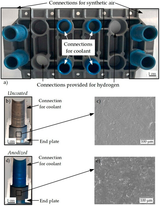
Figure 1.
(a) Anodized end plate with the connections for coolant; (b,d) cross-section of the connection for coolant in uncoated and anodized aluminum alloy end plate; (c,e) scanning electron micrographs of uncoated and anodized surface state.
Generally, corrosion of aluminum and its alloys in aggressive aqueous solutions is the anodic oxidation of aluminum and cathodic reduction of oxygen and water to hydroxide ions, finally forming an oxide layer. Additionally, in the presence of ethylene glycol, the ethylene glycol is reduced, and an aluminum alcohol (Equation (5)) is formed on the surface [12,13,14] as follows:
Anodic reaction: Al → Al3+ + 3e−.
Cathodic reaction: O2 + 2H2O + 4e− → 4OH−.
CH2CH2(OH)2 + e− → OHCH2CH2O− + H.
Overall reaction: Al3+ + 3OH− → Al(OH)3.
Al3+ + 3OHCH2CH2O− → Al(OHCH2CH2O)3.
The presence of aluminum oxide and aluminum alcohol film on the surface is generally corrosion resistant. However, a corrosion attack is possible when the temperature is increased and ethylene glycol decomposes into glycolic acid, oxalic acid, and formic acid [15]. This makes the aluminum alloy more susceptible to corrosion. Zaharieva et al. [16] reported that the presence of glycolic acid in an ethylene glycol–water mixture leads to higher dissolution of aluminum and the formation of corrosion pits. They also reported the formation of white crystalline aluminum–organic precipitates in a few experiments when Al and Al alloys corroded in ethylene glycol–water mixtures. Their 1H NMR spectral data suggested a complex chemical compound that contained H2O, ethylene glycol, and further derivates of ethylene glycol.
Similarly, Zhang et al. [17] also reported the corrosion susceptibility of AA6061 alloy in ethylene glycol–water solution due to the presence of glycolic acid. They further explained that the strong electrostatic force between the negative charge on oxygen atoms of glycolate (salt form of glycolic acid) and aluminum ions leads to corrosion attack.
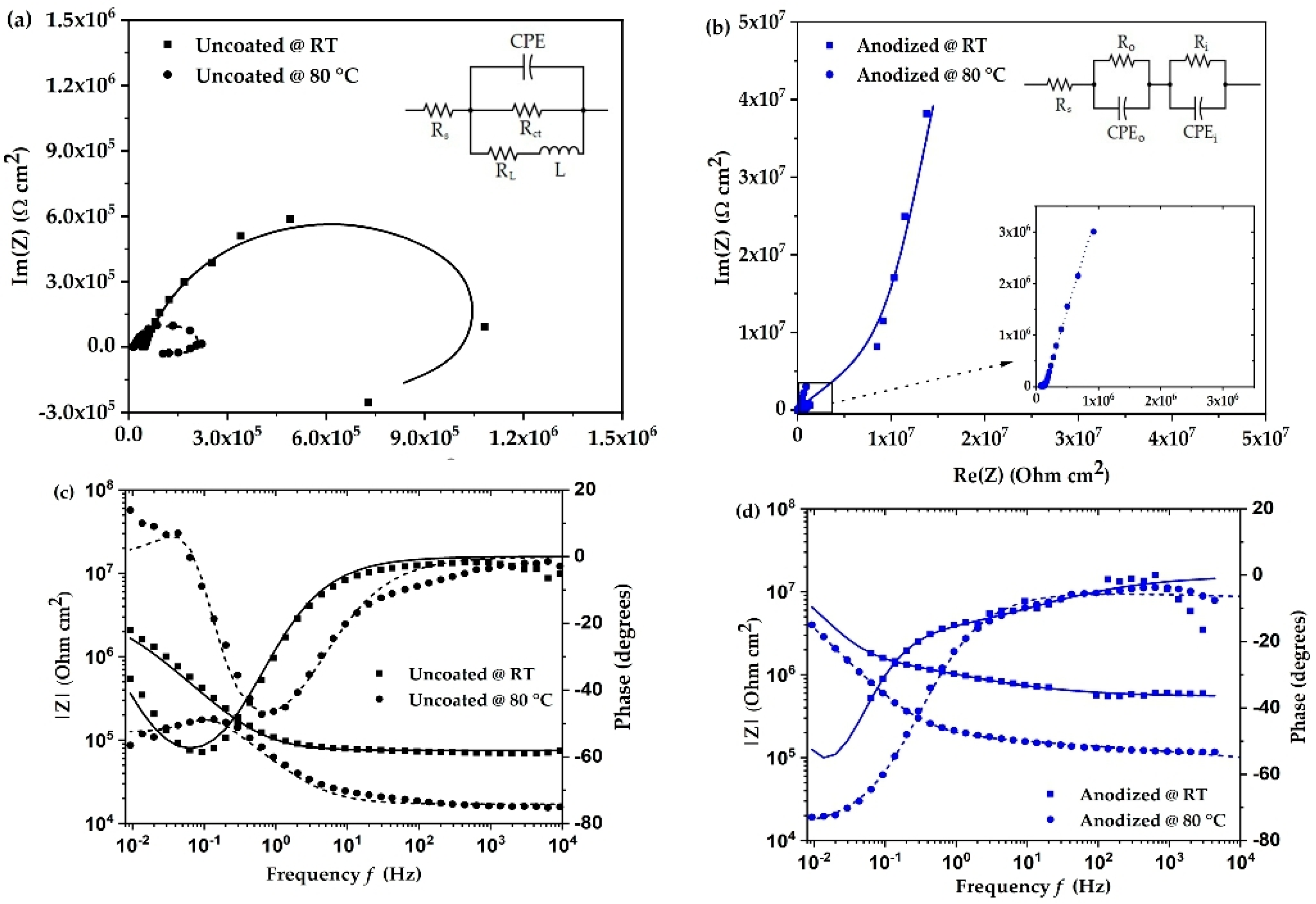
The electrochemical impedance spectra as Nyquist and Bode plots of uncoated and anodized aluminum alloy at room temperature and 80 °C are shown in Figure 2. The impedance behavior of uncoated aluminum alloy (Figure 2a) shows a characteristic semi-circle including an inductive loop in the low frequency region at room temperature and at 80 °C. The presence of an inductive loop is attributed to dissolution of the oxide layer or adsorption of corrosion products on the surface of the aluminum alloy [13,18]. This would mean there is a breakdown of the oxide film present on the surface of the material. The corrosion resistance of the material can be understood by the semi-circle of the impedance spectra. The larger diameter of the semi-circle means that the corrosion resistance is higher. The above analysis is best described by the equivalent circuit shown in Figure 2a. For the uncoated aluminum alloy, the circuit comprises three resistors, one constant phase element, and one inductor. Here, Rs and Rct are the solution and charge transfer resistance, respectively. L and RL are the inductance and its resistance. Constant phase element (CPE) represents the capacitance due to surface inhomogeneity [19]. The effect of temperature on the corrosion mechanism is observed by an increase in the inductive component and a decrease in the diameter of the semi-circle for the uncoated surface. This indicates a reduction in the corrosion durability of the surface.

Figure 2.
(a,b) Nyquist plots and (c,d) Bode plots of uncoated and anodized aluminum alloy in coolant at room temperature (RT) and at 80 °C.
In the case of anodized aluminum alloy (Figure 2b), the impedance characteristic changes significantly, and a strong increase in electrochemical impedance is observed, which, as expected, suggests a clear increase in corrosion resistance of the surface. The overall impedance behavior is best described by the equivalent circuit in Figure 2b, which includes a double-layer system consisting of the outer porous layer and an inner barrier layer. This is represented by a resistor and constant phase element for the outer porous layer (Ro, CPEo) and inner barrier layer (Ri, CPEi) [20]. Due to the low conductivity of the fuel cell coolant and the high electrical resistance of the anodized alloy surface at room temperature, some data points in the impedance fit were irregular and were not considered in order to improve the quality of the fitting results. Similar to the behavior of the uncoated alloy, the impedance of the anodized aluminum alloy decreases as the temperature increases. The overall behavior remains the same as at room temperature, and it is concluded that the surface is highly resistant to corrosion when the temperature rises to 80 °C.
The fitting parameters of the impedance spectra were simulated using Echem Analyst software. The fitting values are shown in Table 2. The solution resistance values are lower than the charge transfer resistance (Rct) for uncoated surfaces. Compared to room temperature, the values of inductance and CPE do not change significantly at 80 °C. In references [21,22,23], it is suggested that charge transfer resistance is inversely proportional to the corrosion rate. For the anodized surface, the inner barrier layer resistance (Ri) can be attributed to charge transfer resistance [20]. On comparing the charge transfer resistance values, we observe that the values of the uncoated surface are lower than that of the anodized surface. At 80 °C, the uncoated surface has the lowest value of 341.1 × 10³ Ω, whereas the anodized surface has the highest value of 171.8 × 10⁶ Ω. This means that the corrosion reaction is accelerated for uncoated surfaces more than anodized surfaces.
Table 2.
Impedance fitting parameters of uncoated and anodized aluminum alloy in coolant at room temperature (RT) and at 80 °C.
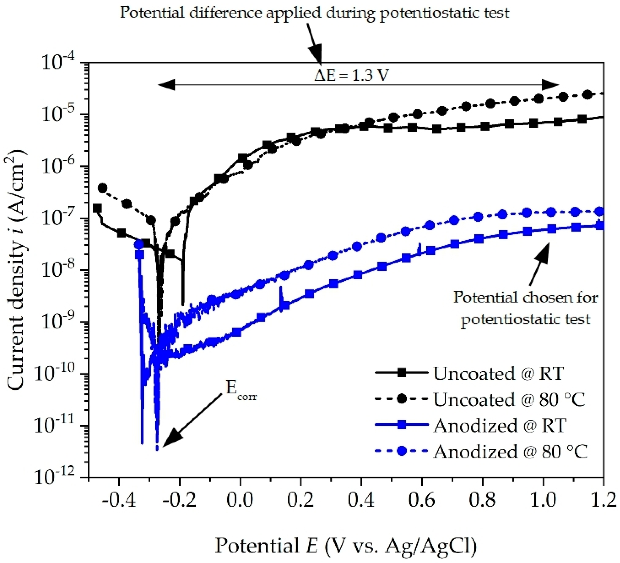
The potentiodynamic polarization curves of the uncoated and anodized aluminum alloy are shown in Figure 3. On comparing the curves, it reveals an almost identical polarization trend, which suggests similar corrosion behavior in contact with the coolant. The values of corrosion potential (Ecorr), corrosion current density (icorr), and corrosion rate (CR) are calculated and given in Table 3. The corrosion rate is calculated in mm/year according to ASTM G1 [24]. The corrosion potential values do not differ significantly and are in the range of −190 mV to −320 mV vs. Ag/AgCl, indicating that the corrosion potential is less affected by temperature even when the surface is coated or not. In contrast, there is a noticeable difference in the measured corrosion current density, which is approximately two to three orders of magnitude higher for the uncoated surface condition when compared to the anodized surface. This effect is attributed to a more reactive surface due to the numerous inhomogeneities and cavities observed and a thinner passive layer for the uncoated initial state (see Figure 1c). Furthermore, the current density of uncoated and anodized aluminum alloy increases when the temperature is increased from room temperature to 80 °C, indicating an increase in the corrosion attack in accordance with Equations (1)–(5). Similar behavior of the temperature effect on the corrosion rate was also reported by [14,25]. From Table 3 it is noticed that the corrosion rate of the uncoated surface increases by an order of magnitude from room temperature to 80 °C.
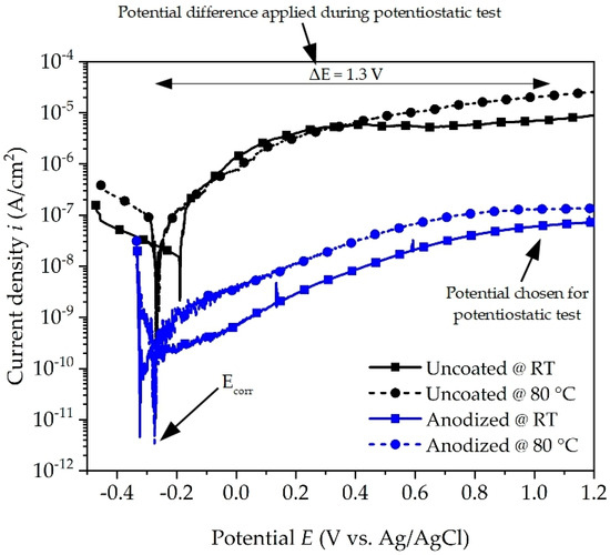
Figure 3.
Potentiodynamic polarization curves of uncoated and anodized aluminum alloy in coolant at room temperature (RT) and at 80 °C.
Table 3.
Fitted electrochemical parameters of uncoated and anodized aluminum alloy in coolant at room temperature (RT) and at 80 °C.
The corrosion current density icorr values of anodized aluminum alloy are lower than those of uncoated aluminum alloy for both temperatures. This difference in current density indicates that the anodized surface is less electrochemically active and hinders the anodic and cathodic processes on the surface in the presence of coolant. The corrosion rate of anodized aluminum alloy has almost similar values, which indicates that irrespective of the temperature, the anodized layer is protective against corrosion. On comparing it with the uncoated alloy, it is observed that the highest value of corrosion rate is for anodized aluminum alloy and the lowest for uncoated aluminum alloy at 80 °C. These results are in good accordance with the impedance spectra. From the results of the polarization test, it is evident that the anodized surface shows better corrosion resistance than the uncoated surface in the presence of the coolant, both at room temperature and at 80 °C.
Figure 4 shows the scanning electron micrographs of the surfaces after the potentiodynamic polarization test. For the uncoated surface condition (Figure 4a,b), scanning electron micrographs show only a weak corrosion attack at room temperature and no significant damage evolution at 80 °C. The corrosion products formed on the uncoated surface were analyzed by EDS, and their elemental composition is given in Table 4. Table 4 only shows elements that have a composition of more than 2 wt. %. The formed corrosion products were found to be of two types: either they were formed by Al-Si-O (marked in a blue square) or by Al-O (marked in a red circle). From the results, it is concluded that the Al-Si-O type corrosion products have similar wt. % for Al and Si at RT and 80 °C. The only exception was an increase in its oxygen composition by two times. This could mean that, when the temperature rises to 80 °C, the increase in corrosion activity leads to breakdown of the passive oxide layer that is gathered on the surface as corrosion products.

Figure 4.
Scanning electron micrographs after potentiodynamic polarization of aluminum alloy: (a) uncoated at room temperature; (b) uncoated at 80 °C; (c) anodized at room temperature; (d) anodized at 80 °C.
Table 4.
Elemental analysis of uncoated aluminum alloy after potentiodynamic polarization at room temperature (RT) and at 80 °C.
In comparison, the anodized condition shows no significant damage either at room temperature or at 80 °C (Figure 4c,d).
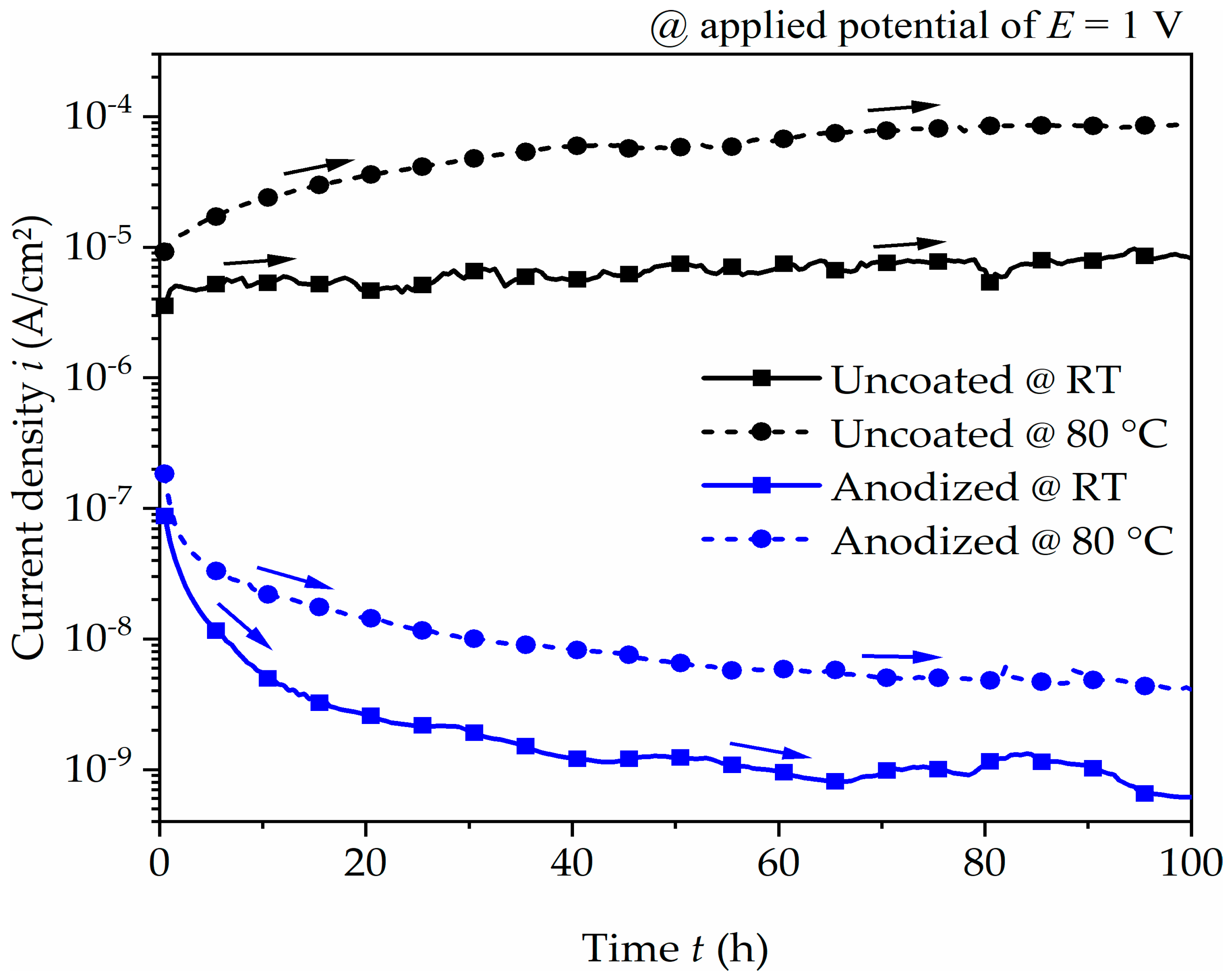
Based on these polarization characteristics, the effect of corrosion performance of the uncoated and anodized surface under constantly applied anodic potential was analyzed for 100 h by potentiostatic polarization test. The current density–time relationships are presented in Figure 5. The uncoated aluminum alloy gradually increases and stabilizes at approximately 10−5 A/cm2 and 10−4 A/cm2 at room temperature and 80 °C, respectively. The consistent trend at room temperature or the weak increase at a temperature of 80 °C indicates a passive behavior or weak corrosion attack. For the anodized aluminum alloy, the current density rapidly drops for the initial few hours before steadying at approximately 10−9 A/cm2 at room temperature and 10−8 A/cm2 at 80 °C. The comparison to the uncoated surface condition clearly shows the improvement in corrosion resistance when the surface has been anodized.
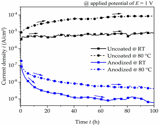
Figure 5.
Current density–time plot of uncoated and anodized aluminum alloy at an applied potential of 1 V for 100 h in coolant at room temperature (RT) and at 80 °C. The arrows indicate the trend of current density as the exposure time increases.
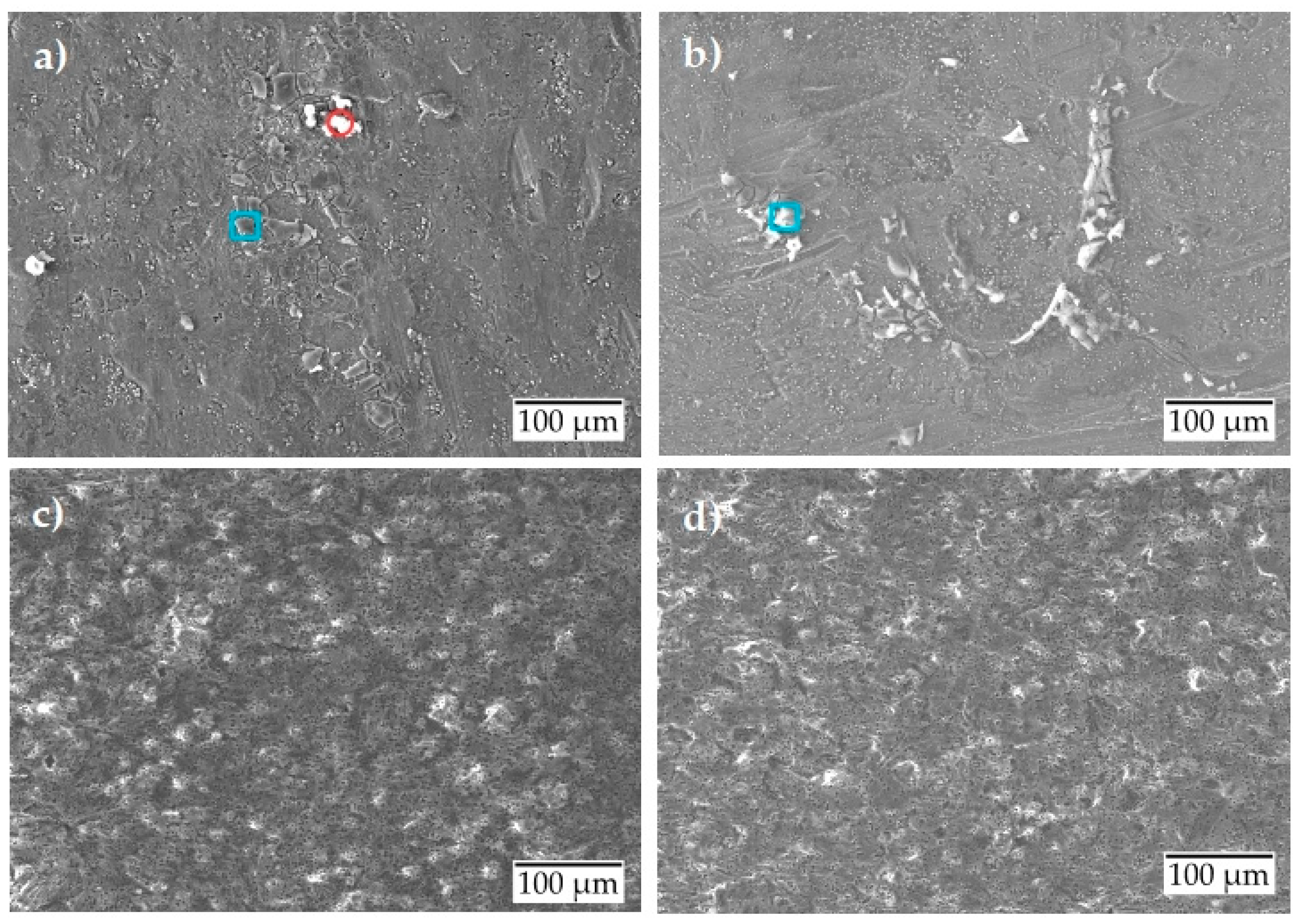
The scanning electron micrographs presented in Figure 6 show slight spalling and corrosion product formation for the uncoated surface condition at room temperature (Figure 6a). A slight local corrosion attack is observed at 80 °C (Figure 6b), indicating the initiation of pitting corrosion. The elemental analysis (Table 5) after the potentiostatic test showed similar results as the potentiodynamic test with the formation of two types of corrosion products. The wt. % of the formed corrosion products is almost the same as those formed during the potentiodynamic test. Under the same test conditions, the anodized surface shows no corrosion, either at room temperature (Figure 6c) or at 80 °C (Figure 6d). The surface behaves almost inertly.
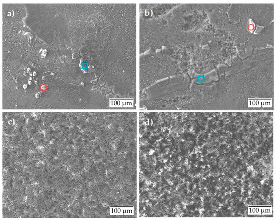
Figure 6.
Scanning electron micrographs after potentiostatic polarization of aluminum alloy: (a) uncoated at room temperature; (b) uncoated at 80 °C; (c) anodized at room temperature; (d) anodized at 80 °C.
Table 5.
Elemental analysis of uncoated aluminum alloy after potentiostatic polarization at room temperature (RT) and at 80 °C.
4. Conclusions
In this study, uncoated and anodized pressure die-cast aluminum alloy AlSi10Mg(Fe) have been characterized for their potential application as end plate material in proton exchange membrane fuel cells using various electrochemical techniques. The changes in surface morphology were studied under application conditions when the surfaces react with the fuel cell coolant at room temperature and at 80 °C.
The results obtained from electrochemical impedance spectroscopy reveal a high corrosion resistance. The potentiodynamic and potentiostatic polarization behavior also indicate a high corrosion protection. Low corrosion attack due to local breakdown of the passive oxide is observed at the uncoated aluminum alloy surface at 80 °C. The corrosion products formed were mainly composed of aluminum–oxygen or aluminum–silicon–oxygen. Compared to the uncoated aluminum alloy, anodized aluminum alloy showed excellent corrosion resistance when exposed to the fuel cell coolant at room temperature and 80 °C. Thus, the anodization of the aluminum alloy is highly recommended to ensure the overall performance and longevity of the fuel cell.
Author Contributions
Conceptualization, D.P.C. and M.M.; methodology, D.P.C. and M.M.; validation, M.M. and L.K.; investigation, D.P.C.; writing—original draft preparation, D.P.C.; writing—review and editing, M.M. and L.K.; visualization, D.P.C.; supervision, M.M.; project administration, M.M. and L.K.; funding acquisition, M.M. and L.K. All authors have read and agreed to the published version of the manuscript.
Funding
This research was funded by Bundesministerium für Verkehr und digitale Infrastruktur (BMVI) as part of the Nationalen Innovationsprogramms Wasserstoff- und Brennstoffzellentechnologie (NIP). The NIP funding program is coordinated by NOW GmbH Nationale Organisation Wasserstoff- und Brennstoffzellentechnologie (NOW). The funding number for the project HZwo:SuSyMobil—Stack- und Systemkomponenten von PEM-Brennstoffzellen für Mobilitätsanwendungen is 03B11022A.
Data Availability Statement
The data presented in this study can be made available on request by contacting the corresponding author. The data are not publicly available as they are part of an ongoing study.
Acknowledgments
We express our gratitude to René Schmiedel from the Department of Advanced Powertrains, TU Chemnitz, for providing the fuel cell coolant. The authors thank Handtmann Leichtmetallgießerei Annaberg GmbH, Annaberg-Buchholz, for manufacturing the end plates. We also extend our gratitude to other partners involved in the project “HZwoSuSy:Mobil”: Fraunhofer IWU, Chemnitz; ESKA Automotive GmbH, Chemnitz; BERND FLACH Präzisionstechnik GmbH & Co.KG, Schönheide; FES GmbH Fahrzeug-Entwicklung-Sachsen, Zwickau; and WÄTAS Wärmetauscher Sachsen GmbH, Olbernhau.
Conflicts of Interest
The authors declare no conflicts of interest.
References
- Kahraman, H.; Akın, Y. Recent Studies on Proton Exchange Membrane Fuel Cell Components, Review of the Literature. Energy Convers. Manag. 2024, 304, 118244. [Google Scholar] [CrossRef]
- Mancino, A.; Menale, C.; Vellucci, F.; Pasquali, M.; Bubbico, R. PEM Fuel Cell Applications in Road Transport. Energies 2023, 16, 6129. [Google Scholar] [CrossRef]
- Wang, Y.; Seo, B.; Wang, B.; Zamel, N.; Jiao, K.; Adroher, X.C. Fundamentals, Materials, and Machine Learning of Polymer Electrolyte Membrane Fuel Cell Technology. Energy AI 2020, 1, 100014. [Google Scholar] [CrossRef]
- Zhang, Y.; Wang, J.; Yao, Z. Recent Development of Fuel Cell Core Components and Key Materials: A Review. Energies 2023, 16, 2099. [Google Scholar] [CrossRef]
- Herzog, D.; Röver, T.; Abdolov, S.; Becker, F.; Gentner, C. Optimization and Design for Additive Manufacturing of a Fuel Cell End Plate. J. Laser Appl. 2022, 34, 042027. [Google Scholar] [CrossRef]
- Asghari, S.; Shahsamandi, M.H.; Ashraf Khorasani, M.R. Design and Manufacturing of End Plates of a 5kW PEM Fuel Cell. Int. J. Hydrogen Energy 2010, 35, 9291–9297. [Google Scholar] [CrossRef]
- Stein, T.; Ein-Eli, Y. Challenges and Perspectives of Metal-Based Proton Exchange Membrane’s Bipolar Plates: Exploring Durability and Longevity. Energy Technol. 2020, 8, 2000007. [Google Scholar] [CrossRef]
- Pozio, A.; Silva, R.F.; De Francesco, M.; Giorgi, L. Nafion Degradation in PEFCs from End Plate Iron Contamination. Electrochim. Acta 2003, 48, 1543–1549. [Google Scholar] [CrossRef]
- Vargel, C. The Corrosion of Aluminium. In Corrosion of Aluminium; Elsevier: Amsterdam, The Netherlands, 2020; pp. 41–61. ISBN 978-0-08-099925-8. [Google Scholar]
- Paz Martínez-Viademonte, M.; Abrahami, S.T.; Hack, T.; Burchardt, M.; Terryn, H. A Review on Anodizing of Aerospace Aluminum Alloys for Corrosion Protection. Coatings 2020, 10, 1106. [Google Scholar] [CrossRef]
- Fu, Y.; Hou, M.; Yan, X.; Hou, J.; Luo, X.; Shao, Z.; Yi, B. Research Progress of Aluminium Alloy Endplates for PEMFCs. J. Power Sources 2007, 166, 435–440. [Google Scholar] [CrossRef]
- Liu, Y.; Cheng, Y.F. Effects of Coolant Chemistry on Corrosion of 3003 Aluminum Alloy in Automotive Cooling System. Mater. Corros. 2010, 61, 574–579. [Google Scholar] [CrossRef]
- Zhang, G.A.; Xu, L.Y.; Cheng, Y.F. Mechanistic Aspects of Electrochemical Corrosion of Aluminum Alloy in Ethylene Glycol–Water Solution. Electrochim. Acta 2008, 53, 8245–8252. [Google Scholar] [CrossRef]
- Chen, X.; Tian, W.; Li, S.; Yu, M.; Liu, J. Effect of Temperature on Corrosion Behavior of 3003 Aluminum Alloy in Ethylene Glycol–Water Solution. Chin. J. Aeronaut. 2016, 29, 1142–1150. [Google Scholar] [CrossRef]
- Vargel, C. Alcohols, Ethers, Thiols and Phenols. In Corrosion of Aluminium; Elsevier: Amsterdam, The Netherlands, 2004; pp. 473–487. ISBN 978-0-08-044495-6. [Google Scholar]
- Zaharieva, J.; Milanova, M.; Mitov, M.; Lutov, L.; Manev, S.; Todorovsky, D. Corrosion of Aluminium and Aluminium Alloy in Ethylene Glycol–Water Mixtures. J. Alloys Compd. 2009, 470, 397–403. [Google Scholar] [CrossRef]
- Zhang, D.Q.; Zhou, L.X.; Rao, C.Y.; Gao, L.X. Effect of pH and Glycolic Acid on Corrosion of AA6061 Alloy in Ethylene Glycol–Water Solution. Mater. Corros. 2014, 65, 31–37. [Google Scholar] [CrossRef]
- Chen, S.; Fan, J.; Lei, T.; Zou, Z.; Yi, J.; Tan, S.; Zheng, X. Effect of Oxalic Acid on the Corrosion of 6063 Aluminum Alloy in Ethylene Glycol-Water Solution in Presence of Ammonium Alcohol Polyvinyl Phosphate. Int. J. Electrochem. Sci. 2024, 19, 100540. [Google Scholar] [CrossRef]
- Zhang, G.A.; Xu, L.Y.; Cheng, Y.F. Investigation of Erosion–Corrosion of 3003 Aluminum Alloy in Ethylene Glycol–Water Solution by Impingement Jet System. Corros. Sci. 2009, 51, 283–290. [Google Scholar] [CrossRef]
- Miramontes, J.C.; Gaona Tiburcio, C.; García Mata, E.; Esneider Alcála, M.Á.; Maldonado-Bandala, E.; Lara-Banda, M.; Nieves-Mendoza, D.; Olguín-Coca, J.; Zambrano-Robledo, P.; López-León, L.D.; et al. Corrosion Resistance of Aluminum Alloy AA2024 with Hard Anodizing in Sulfuric Acid-Free Solution. Materials 2022, 15, 6401. [Google Scholar] [CrossRef]
- Zhang, X.; Liu, X.; Dong, W.; Hu, G.; Yi, P.; Huang, Y.; Xiao, K. Corrosion Behaviors of 5A06 Aluminum Alloy in Ethylene Glycol. Int. J. Electrochem. Sci. 2018, 13, 10470–10479. [Google Scholar] [CrossRef]
- Salim Kaiser, M.; Abdu, A. Investigation on Electrochemical Corrosion Behavior of Eutectic Al-Si Automotive Alloy in 0.2 M HCl, 0.2 M NaOH, and 0.2 M NaCl Environments. J. Chem. Technol. Metall. 2023, 58, 969–980. [Google Scholar] [CrossRef]
- Fouda, A.S.; Mohamed, F.S.; El-Sherbeni, M.W. Corrosion Inhibition of Aluminum–Silicon Alloy in Hydrochloric Acid Solutions Using Carbamidic Thioanhydride Derivatives. J. Bio-Tribo-Corros. 2016, 2, 11. [Google Scholar] [CrossRef]
- G01 Committee ASTM International. Practice for Calculation of Corrosion Rates and Related Information from Electrochemical Measurements; ASTM International: West Conshohocken, PA, USA, 1964. [Google Scholar] [CrossRef]
- Niu, L.; Cheng, Y.F. Electrochemical Characterization of Metastable Pitting of 3003 Aluminum Alloy in Ethylene Glycol–Water Solution. J. Mater. Sci. 2007, 42, 8613–8617. [Google Scholar] [CrossRef]

Disclaimer/Publisher’s Note: The statements, opinions and data contained in all publications are solely those of the individual author(s) and contributor(s) and not of MDPI and/or the editor(s). MDPI and/or the editor(s) disclaim responsibility for any injury to people or property resulting from any ideas, methods, instructions or products referred to in the content. |
© 2025 by the authors. Licensee MDPI, Basel, Switzerland. This article is an open access article distributed under the terms and conditions of the Creative Commons Attribution (CC BY) license (https://creativecommons.org/licenses/by/4.0/).