Article

Effect of Laser Welding on Performance of the B1500HS/340LA High-Strength Steel

1
Key Laboratory of Advanced Forging & Stamping Technology and Science of Ministry of Education, Yanshan University, Qinhuangdao 066004, China
2
School of Mechanical Engineering, Yanshan University, Qinhuangdao 066004, China
3
Ningbo L.K. Technology Co., Ltd., Ningbo 315000, China
*
Author to whom correspondence should be addressed.
Metals 2025, 15(4), 393; https://doi.org/10.3390/met15040393
Submission received: 9 March 2025 / Revised: 29 March 2025 / Accepted: 30 March 2025 / Published: 1 April 2025
(This article belongs to the Section Welding and Joining)

Abstract

:
In this study, high-strength steels B1500HS and B340LA were used as base materials, and laser welding experiments were conducted within a parameter range of welding power from 1500 W to 3000 W and welding speed from 15 mm/s to 35 mm/s. Microstructural analysis, microhardness testing, and uniaxial tensile tests were performed to systematically investigate the effects of different welding parameters on the weld microstructure and macroscopic mechanical properties, leading to the identification of an optimal welding parameter range that avoids defect-prone regions. The bending formability of tailor-welded blanks (TWBs) was evaluated using hat-shaped bending tests, with finite element simulations employed to analyze the effects of welding parameters on stress distribution and material hardening behavior. Based on the identified high-quality welding parameters, a suitable welding parameter range for reverse bending conditions was determined, effectively improving the bending formability of TWBs and providing theoretical guidance and experimental support for their engineering applications.

1. Introduction

Tailor-welded blank (TWB) technology is widely used in the automotive industry to enhance safety and optimize weight, leading to reduced fuel consumption and lower pollutant emissions [1].
Laser welding is one of the most effective methods for fabricating high-strength steel TWBs, producing welds of high quality, with narrow heat-affected zones (HAZs) and minimal distortion. However, welding parameters critically influence weld quality, with improper parameter selection potentially causing defects such as incomplete fusion, porosity, and undercut [2,3]. Khan et al. [4,5] utilized laser beam defocusing techniques to control fusion zone (FZ) geometry, significantly improving weld surface morphology and eliminating severe concavity defects. Orturk et al. [6] conducted uniaxial tensile tests on DP600/DP800 TWBs with varying thickness ratios and observed significant changes in stress distribution and strain localization, which were influenced by grain size in the microstructure and thickness ratio. Researchers have investigated the effects of laser welding on the microstructure and mechanical properties of quenching and partitioning (Q&P) steels and dual-phase (DP) steels. Both materials exhibited softening zones in the HAZ caused by tempered martensite, which adversely affected the mechanical performance of the weld joints [7,8]. He et al. [9] analyzed the influence of laser welding parameters on the mechanical properties of Al-Si-coated 22MnB5 hot stamping steels. Their results indicated that the tensile shear load increased with higher laser power and decreased with lower welding speed. Hong et al. [10] found that Al-Si coatings melted into the weld during welding, promoting ferrite formation during quenching in the hot stamping process and reducing the weld area’s thermal stamping performance. Similarly, Tuncel et al. [11] reported that increased heat input caused grain coarsening in the HAZ of 22MnB5 steel welds, leading to a hardness reduction of up to 39% compared to the base metal. Moayedi et al. [12] demonstrated the optimal formability of TWBs under tensile deformation when the welding direction was perpendicular (90°) to the rolling direction. Under plane-strain conditions, formability was highest when the two directions were aligned (0°). Furthermore, recent studies have identified the HAZ as the weakest and most failure-prone region in TWBs. Failure models based on hardness distribution across different weld zones have been proposed [13,14]. Rojek et al. [15] proposed several methods for evaluating the mechanical properties of TWB weld joints, including metallographic observations, uniaxial tensile testing, microhardness measurements, and indentation tests coupled with inverse numerical analysis. These approaches provided a comprehensive assessment of weld quality and yielded reliable results.
Springback, a common issue that arises during the bending of sheet materials, becomes more complex in TWBs due to differences in material properties and thickness between the two sides of the blank [16]. Studies have validated the feasibility of welding and forming high-strength steel TWBs with significant base metal strength differences using V-bending tests, consistently observing fracture initiation in the weld region [17,18]. Numerical simulations have also been employed to evaluate how thickness and strength differences influence stress and strain distributions and forming limits in TWBs [19,20]. Lee et al. [21] assessed the energy absorption capacity of high-strength steel TWBs for B-pillars through three-point bending tests, demonstrating a proportional relationship between bending strength and energy absorption. Huang et al. [22] developed two mathematical response models to predict bending distortion in laser-welded joints, optimizing process parameters for minimizing bow distortion and exploring the influence of laser parameters on weld distortion. However, research specifically focused on the impact of laser welding parameters on the bending and forming quality of TWBs remains limited.
This study investigates the welding performance of B1500HS/340LA high-strength steel TWBs, with a particular focus on parameter optimization through hat-shaped bending tests to establish a suitable parameter range for industrial applications. In Section 2, different welding process parameters were selected to weld B1500HS and B340LA high-strength steels. The welded joints were subsequently characterized through metallographic examination and microhardness testing, with specimens extracted from the weld zone for uniaxial tensile testing. Section 3 presents a comprehensive analysis of the experimental results, leading to the identification of optimal welding parameter ranges that yield high-quality welds. Section 4 introduces a novel approach, combining hat-shaped bending tests with finite element simulations to evaluate the bending formability of TWBs. This integrated methodology enables detailed analysis of stress distribution and material hardening behavior in formed components, thereby facilitating further refinement of welding parameters to prevent defect formation during the forming process.

2. Experimental Procedure

2.1. Base Materials

The materials used in the investigation were B1500HS and B340LA cold-rolled high-strength steels, manufactured by the Baowu Iron and Steel Group (Shanghai, China), and the thickness of the sheets was 1.2 mm. The compositions of the two materials are presented in Table 1 and Table 2. The microstructure of B1500HS consists of ferrite and pearlite, as shown in Figure 1a; B340LA consists of ferrite, as shown in Figure 1b.

2.2. Laser Welding Experiments

The laser welding experiments were conducted using a German IPG fiber laser welding system (Ytterbium Laser System 4000, IPG Photonics GmbH, Burbach, Germany), integrated with a KUKA six-axis robotic arm (KUKA AG, Augsburg, Germany). The base materials, B1500HS and B340LA high-strength steel sheets, were 60 mm × 20 mm × 1.2 mm in size. Prior to welding, the surfaces near the welding zones were polished to remove corrosion and oxide layers. During welding, the laser beam was directed perpendicularly to the sheet surface. Argon gas, with a flow rate of 15 L/min, was employed as the shielding gas, directed at a 45° angle relative to both the sheet surface and the laser beam. The welding direction was perpendicular to the rolling direction of the base materials, and the laser spot size had a diameter of 2 mm. The laser beam profile is modeled as a conical heat source, where the effective thermal radius decreases linearly along the depth direction and the cross-sectional heat flux follows a Gaussian distribution. A specialized welding jig was used to secure the two high-strength steel sheets to the workbench, maintaining a clamping gap of 0.1 mm. The experimental setup is shown in Figure 2; the laser welding parameters are provided in Table 3.

2.3. Microstructure and Microhardness Testing

To investigate the influence of welding process parameters on the microstructure and mechanical properties of the weld joints, microstructure observations and microhardness tests were conducted. Metallographic specimens with sizes of 10 mm × 10 mm were cut from the cross-section of the weld joints. The specimens were mounted, ground, and polished, then etched with a 4% nitric acid alcohol solution to obtain the microstructure. Microhardness measurements were taken using an FM-ARS9000 microhardness tester (Future-Tech Corp, Tokyo, Japan), focusing on the base materials, fusion zone (FZ), and heat-affected zone (HAZ).

2.4. Mechanical Properties Testing

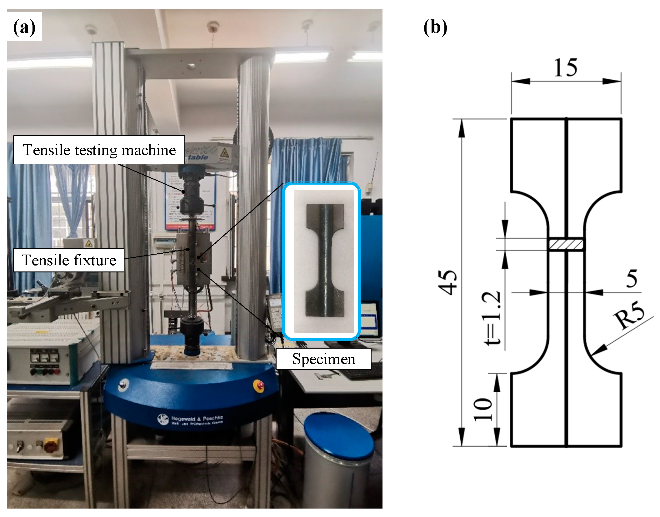
Uniaxial tensile tests were performed at room temperature to assess the effects of varying laser welding parameters on the mechanical properties of the high-strength steel TWBs. The tensile tests were carried out using an INSPEKT Table 100 kN universal testing machine (Hegewald & Peschke Meß- und Prüftechnik GmbH, Niederfrauendorf, Germany), as seen in Figure 3a. The specimens were prepared according to the Chinese National Standard GB/T 228.1-2021 [25], “Metallic Materials—Tensile Testing—Room Temperature Test Method”, as illustrated in Figure 3b. The specimens were stretched at a strain rate of 0.1 s⁻1 until fracture. To ensure accuracy, each test was repeated three times.

3. Experimental Results and Discussion

3.1. Macroscopic Weld Quality of TWBs

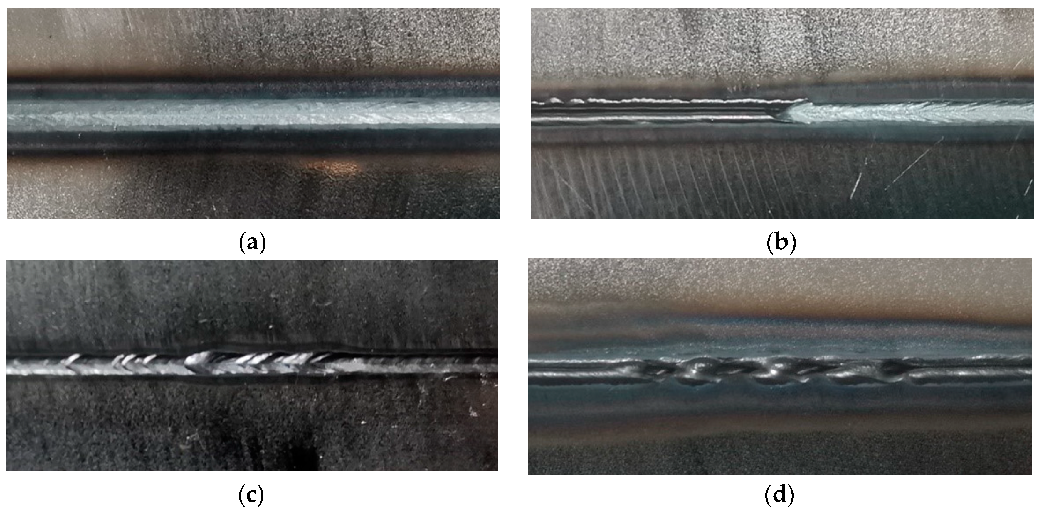
The macroscopic surface quality of welds is shown in Figure 4. High-quality weld joints achieved under optimal laser welding parameters are displayed in Figure 4a. At 1500 W-35 mm/s, the weld width was too narrow, resulting in incomplete fusion, as seen in Figure 4b. At 2000 W-35 mm/s, welding discontinuities and inconsistent weld widths were observed, as illustrated in Figure 4c. At 3000 W-30 mm/s, porosity defects were evident in welds, and the weld width was excessively large, as shown in Figure 4d.

3.2. Microstructure and Hardness

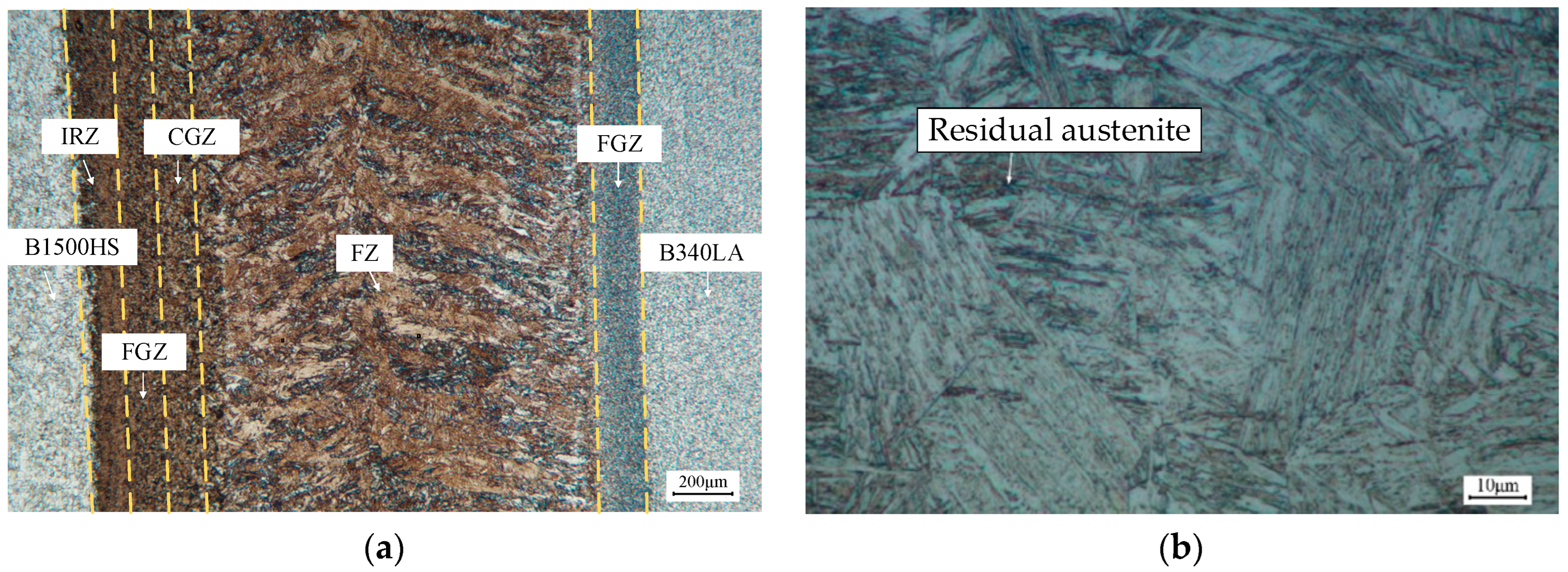
The weld joint of the high-strength steel TWBs consists of four zones: B1500HS base material, B340LA base material, FZ, and HAZ, as shown in Figure 5a. The microstructure in the FZ consists primarily of lath martensite, with a small amount of residual austenite, as shown in Figure 5b. The regions adjacent to the FZ center and near the base materials are part of the HAZ. During the welding process, the thermal cycle changes with the distance from the heat source, which affects the microstructural transformation of the HAZ [26]. Based on the microstructure type and grain size, the HAZ on the B1500HS side can be divided into a coarse grain zone (CGZ), fine grain zone (FGZ), and incomplete recrystallization zone (IRZ). The HAZ on the B340LA side transitions from the FZ to the original microstructure through an FGZ, as shown in Figure 5a.
In the CGZ and FGZ, the heating temperatures exceeded the Ac3 critical point, resulting in full austenitization during the welding process and subsequent martensite formation during rapid cooling [27]. The smaller austenite grains in the FGZ restricted the growth of martensite, resulting in finer martensite compared to the CGZ. The microstructural morphologies of the CGZ and FGZ are shown in Figure 6a. The IRZ, where the heating temperature was between Ac3 and Ac1, underwent partial austenitization, with a martensitic-ferritic microstructure formed after rapid cooling (Figure 6b).
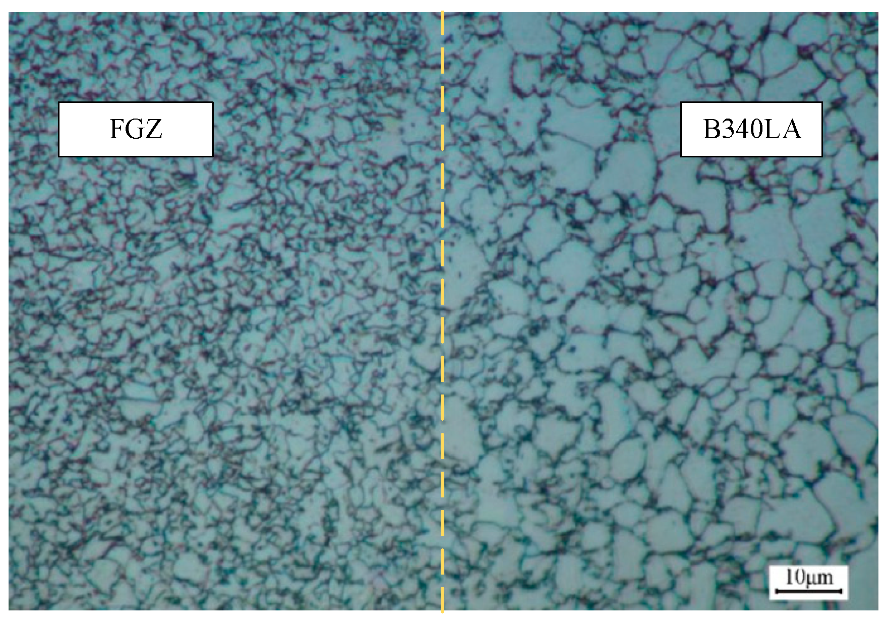
On the B340LA side, no martensitic structure was observed during welding. The FGZ adjacent to the original microstructure of the B340LA base material retained its ferritic structure; however, the welding thermal cycle refined the ferrite grains in this region, resulting in smaller grain sizes than those in the original microstructure (Figure 7).
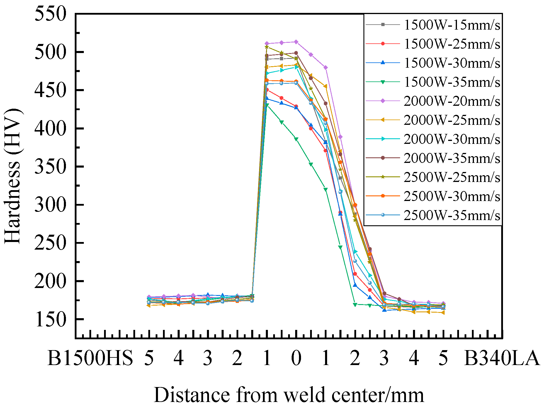
Hardness measurements were conducted at 0.5 mm intervals from the center of the FZ, extending perpendicularly to the weld seam on both the B1500HS and B340LA sides. The hardness distribution for the weld joints under different laser welding parameters are shown in Figure 8. The hardness of the B1500HS base material was approximately HV170, while that of the B340LA base material was approximately HV160. The hardness of the FZ and HAZ increased sharply from HV160–170 to a range of HV450–500. Furthermore, the hardness values in these regions varied significantly with changes in laser welding parameters. The hardness peak may be associated with transformation hardening and residual stress distribution.

3.3. Effect of Different Laser Welding Parameters on Microstructure and Hardness

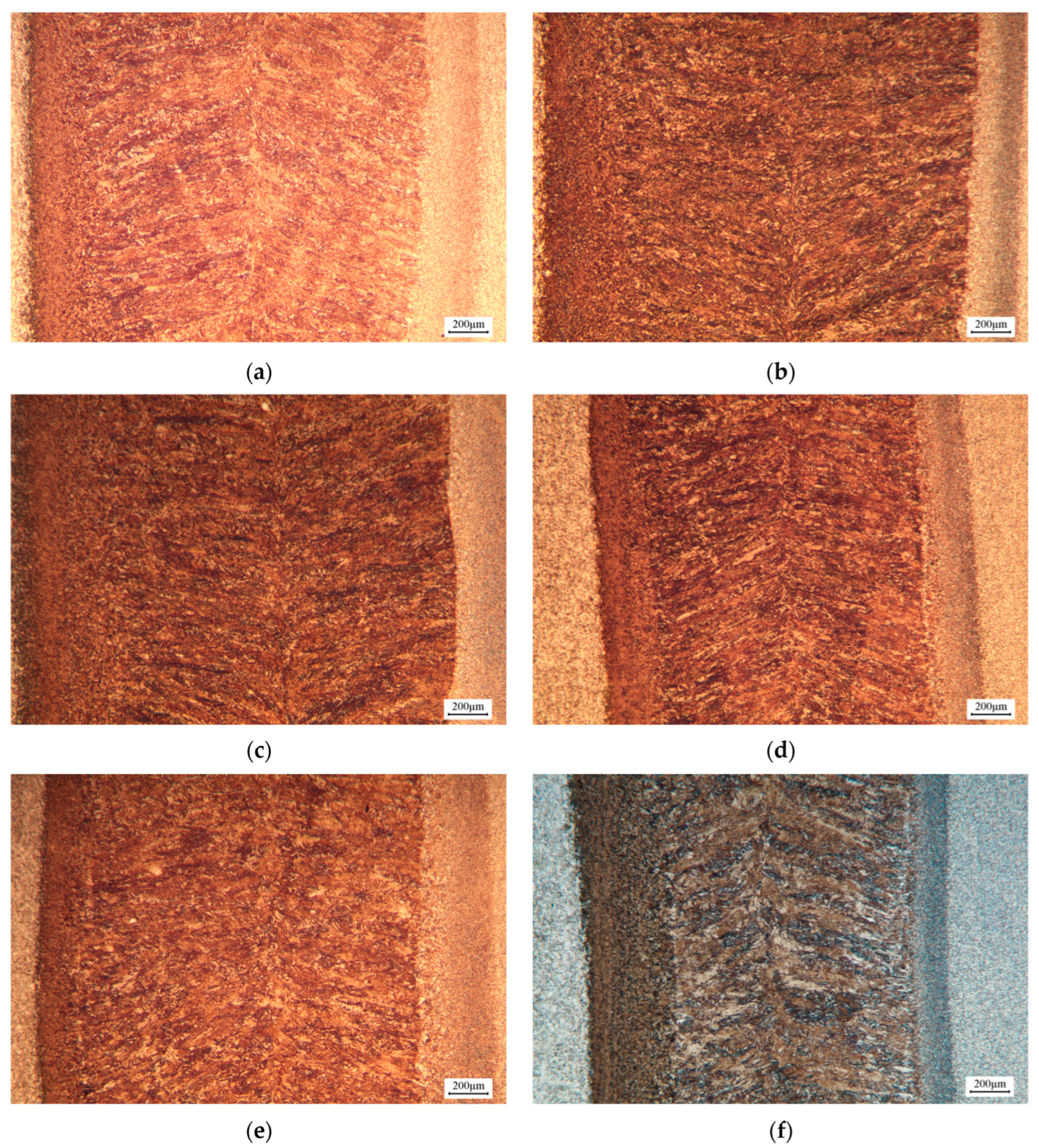
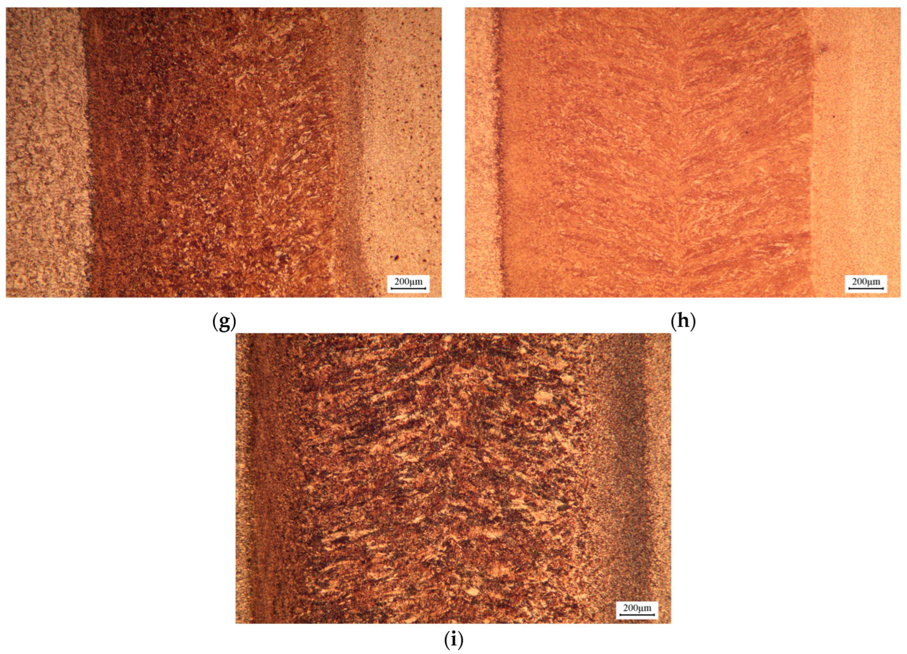
The microstructures of welded joints under different laser welding parameters are shown in Figure 9. At a constant welding speed, increasing welding power resulted in a wider FZ and HAZ, although the width increase in the HAZ was less pronounced. This is due to higher heat input, which allows thermal energy to penetrate deeper into the material, while the effect on heat loss during transfer remains limited. As a result, temperature variations near the edges of the HAZ are minimal, leading to only slight changes in the HAZ area [28]. Additionally, higher welding power provides sufficient heat input to achieve a more uniform microstructure, as shown in Figure 9c,f,i.
The hardness distribution measured in Figure 8 shows a strong correlation with the microstructural features of the welded joints. On the B1500HS base material side, the FZ and HAZ primarily consist of martensite. As welding power increased, the FZ and HAZ expanded, resulting in a corresponding increase in the martensitic region. Moreover, the microstructure became more uniform, and the hardness values increased. For instance, the welded joint produced at 2500 W exhibited a more uniform microstructure and higher hardness compared to those welded at 1500 W or 2000 W. Therefore, when selecting welding power, a higher power should be used as long as welding defects are avoided.
The influence of welding speed on welding quality is significantly less pronounced than that of welding power; however, it is necessary to select a welding speed that matches welding power, as an unsuitable speed can lead to defects such as porosity and weld seam discontinuities [29]. As shown in Figure 9a,d,g, for a constant welding power of 1500 W, increasing the welding speed decreases the heat input at the weld joint. This decrease diminishes the amount of molten metal, reduces the width of the FZ and HAZ, and promotes the growth and dispersion of martensitic structures. Furthermore, as shown in Figure 8, the hardness distribution of the weld joints indicates a general decline in overall hardness as welding speed increases. These results demonstrate that welding speed should not be excessively high or low in order to ensure optimal weld joint properties.
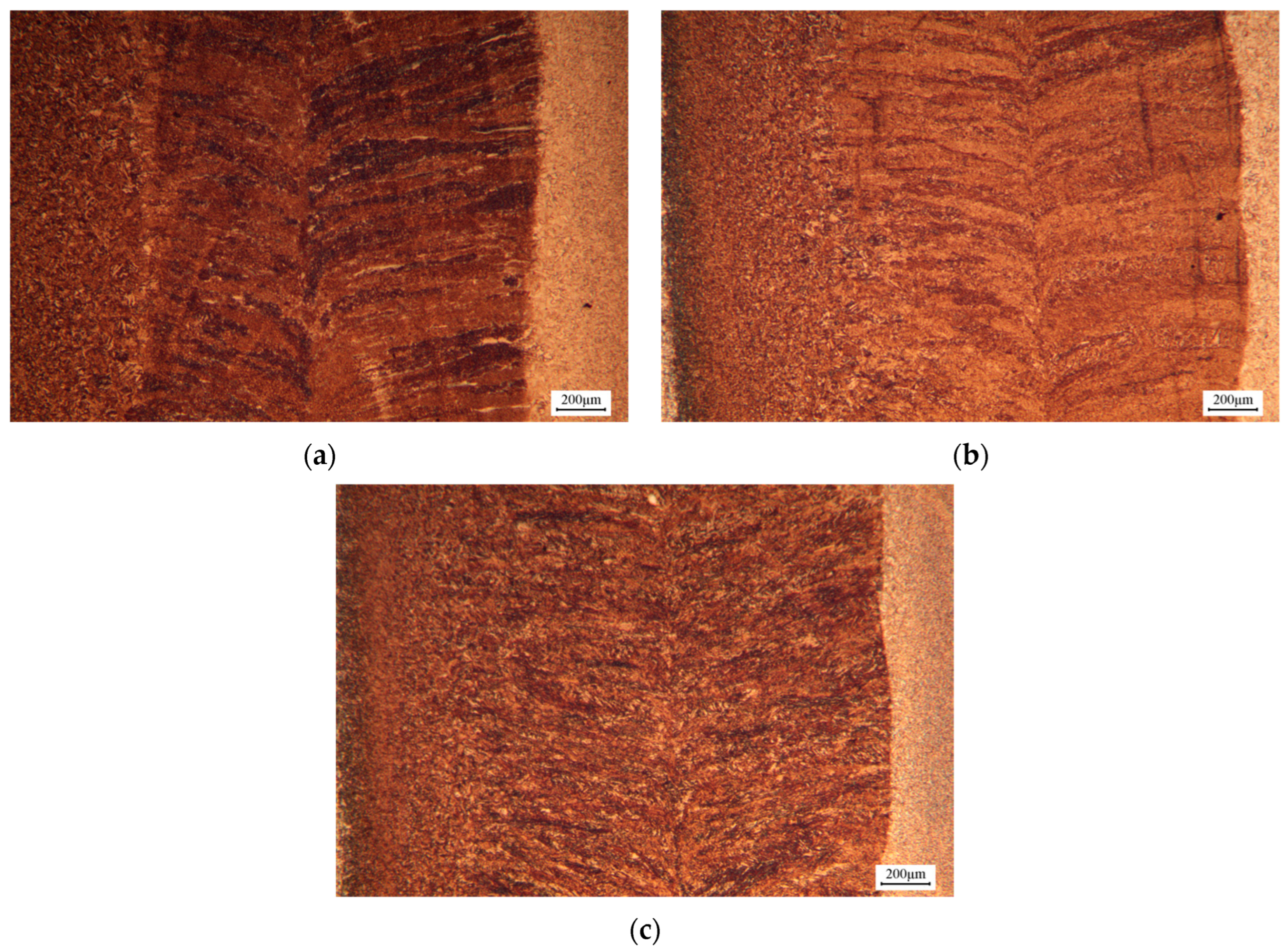
Figure 10 illustrates the microstructural distribution of welded joints under different welding parameters with an identical theoretical heat input of 100 J/mm. Under this constant heat input condition, the weld joint produced with lower welding power and speed exhibits a wider FZ and HAZ, as seen in Figure 10a. As the welding power and speed increase, a moderate reduction in the width of both FZ and HAZ is observed, as in Figure 10b,c. Comparative analysis reveals that the B1500HS high-strength steel side produces finer grain structures in both the FGZ and CGZ of the HAZ under higher welding power and speed combinations, with smoother transitions between different microstructural zones.
The hardness distribution analysis under identical heat input conditions (Figure 8) shows the following trend: 2000 W-20 mm/s > 2500 W-25 mm/s > 1500 W-15 mm/s. At 2000 W-20 mm/s, the base material receives a uniform and sufficient heat input, optimizing the weld quality. In contrast, the other two parameter combinations result in either insufficient or excessive heat input, leading to reduced hardness values due to suboptimal microstructural development.

3.4. Effect of Different Welding Process Parameters on Mechanical Properties

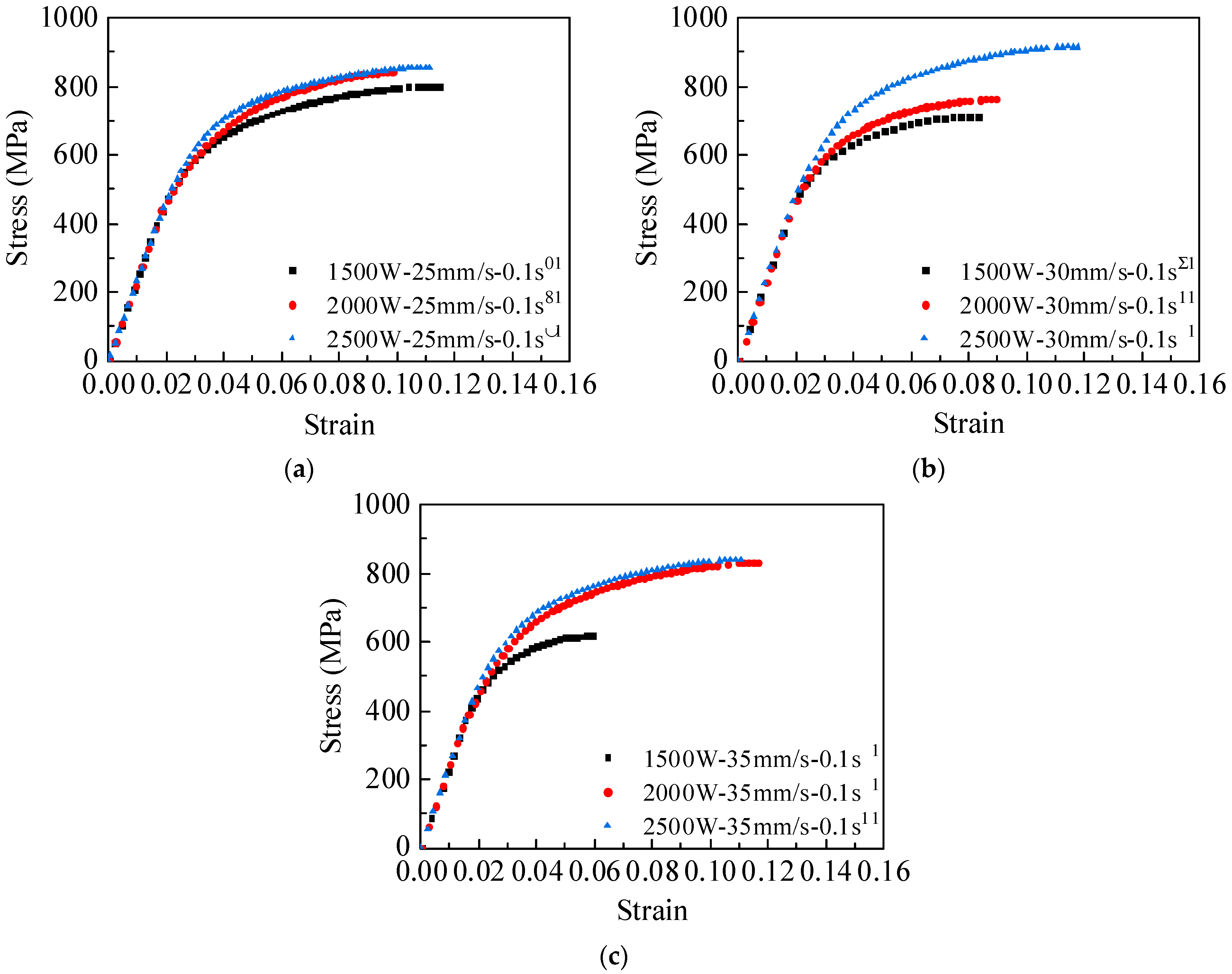
The true stress–strain curves from uniaxial tensile tests of the base metals in TWBs are presented in Figure 11. At room temperature, the yield strength and ultimate strength of B1500HS high-strength steel were 330 MPa and 590 MPa, respectively, while those of B340LA high-strength steel were 360 MPa and 535 MPa. The fracture strain for both high-strength steels was approximately 0.2. Figure 12 shows the true stress–strain curves of the weld joint in TWBs under different welding speeds and powers.
The heat input is calculated by the following formula:
Q = P ν
where Q represents the heat input (in J/mm), P is laser power (in W), and v denotes welding speed (in mm/s). As shown in Figure 12a, at a welding speed of 25 mm/s, all welding power levels provided sufficient heat input (Q > 70  J/mm). The welded joints exhibited true stress values ranging from 700 MPa to 800 MPa, with consistent elongation across samples. In Figure 12b,c, at welding speeds of 30 mm/s and 35 mm/s, specimens welded at 1500 W fractured prematurely. The excessive welding speed caused insufficient heat input (Q < 70  J/mm), resulting in an overly narrow weld seam. The tensile strength decreased by 22% under 1500 W-35 mm/s due to incomplete fusion. Increasing the welding power improved elongation, restoring mechanical properties to the levels observed in Figure 12a. When Q > 70 J/mm, the fracture strain exceeds 10%, indicating sufficient heat input to ensure complete penetration of the weld. At laser welding parameters of 2500 W-30 mm/s, the welded joint achieved an elongation of 12% and an ultimate strength of 915 MPa, demonstrating superior mechanical properties compared to other welding parameter combinations.

3.5. Optimal Welding Parameter Range for High-Quality Welds

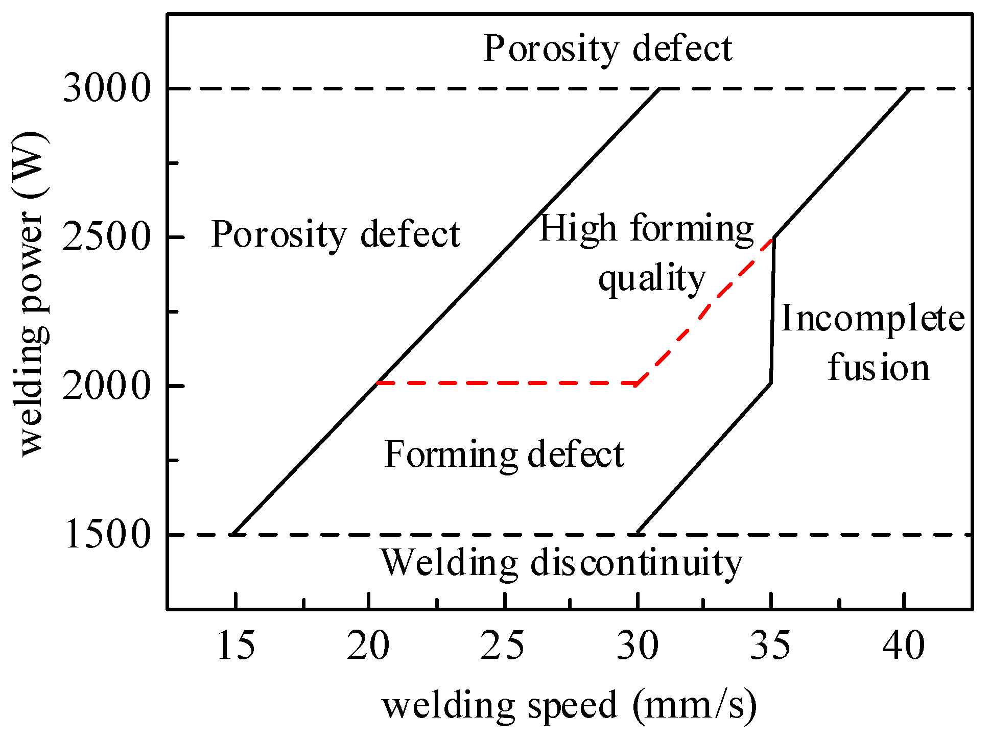
By integrating the findings from Section 3.3 and Section 3.4, which analyze the effects of different welding parameters on the microstructure of welded joints, grain morphology distribution, hardness distribution, and mechanical properties, the weld quality under various welding parameters is summarized in Table 4. The optimal welding parameter range for TWBs with superior welding performance is illustrated in Figure 13.

4. Forming Quality Evaluation of TWBs

4.1. Bend-Forming Tests and Finite Element Modeling

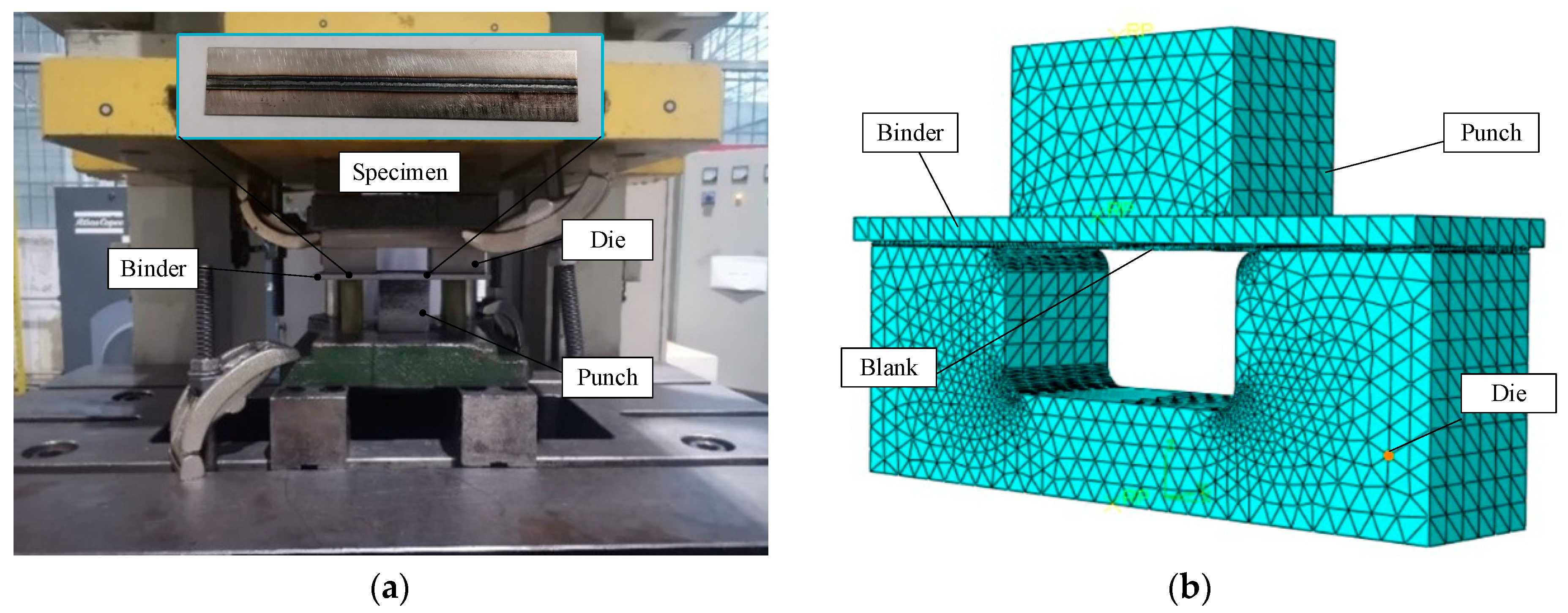
To investigate the effects of different laser welding parameters on the bend-forming quality of TWBs, a hat-shaped bend-forming test was designed. Specimens measuring 150 mm × 30 mm × 1.2 mm were extracted along the weld seam from high-strength steel TWBs using an electrical discharge wire-cutting machine. The tests were performed using an H1F80 servo press, as seen in Figure 14a, with the specimens positioned on the die and the stroke of the press adjusted to 30 mm.
Finite element modeling was performed in ABAQUS 6.14 based on the die dimensions used in the hat-shaped bend-forming tests, as shown in Figure 4b. The finite element model consisted of a punch, die, blank holder, and TWB sheet. The weld seam width was set to 5 mm, parallel to the longer side of the sheet. The gap between the punch and die was 1.15 times the sheet thickness, and the fillet radii of both the punch and die were 5 mm. Three different material properties were assigned to the base materials and the weld seam. The flow stress–strain relationships of the materials are provided in Section 3.4. Young’s modulus for B1500HS, B340LA, and the weld seam are listed in Table 5. The sheet was meshed with C3D8R elements, and the punch, die, and blank holder were meshed with R3D3 elements as rigid, discrete bodies. The meshing results are shown in Figure 14b. Analysis was divided into forming and springback stages to simulate the bending process of the hat-shaped component.

4.2. Results of Bending Tests and Finite Element Analysis

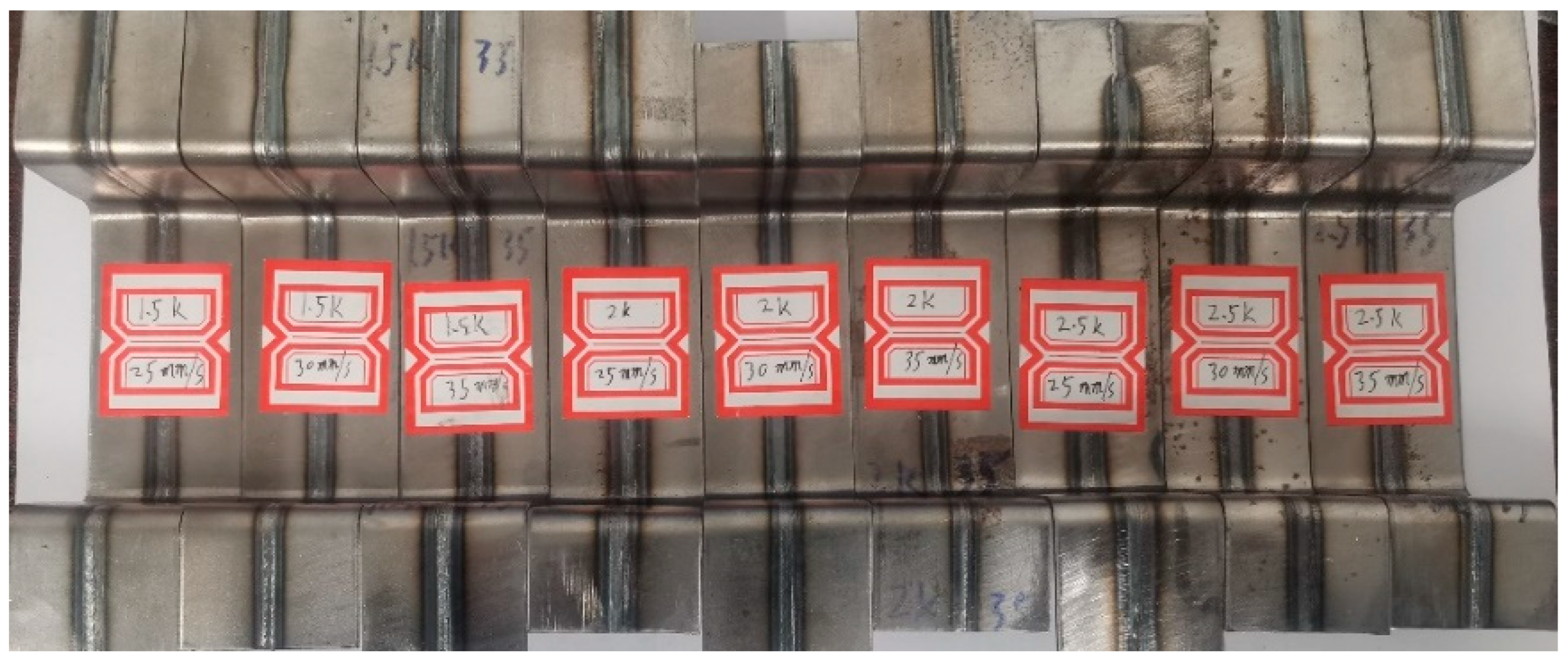
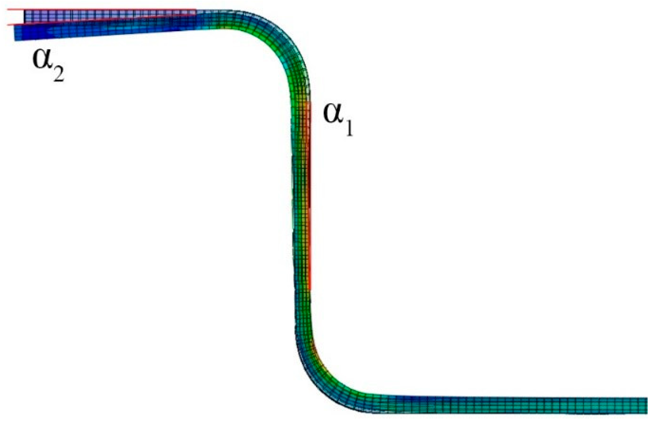
Figure 15 shows the hat-shaped parts obtained from bending tests under different laser welding parameters. The springback angles of the sidewall α 1 and flange α 2 were measured using a co-ordinate measuring machine, as shown in Figure 16, with multiple measurements taken to minimize error and the average value recorded. The results are listed in Table 6. Significant variations in the springback angles were observed across different laser welding parameters. The following section analyzes the influence of laser welding parameters on the stress and strain distributions, as well as the springback angles, based on bending simulation results.
The simulation results, shown in Figure 15, indicated that stress was primarily concentrated in the sidewall region of the hat-shaped parts. After springback, higher stress was observed near the sidewall adjacent to the rounded corner. Due to the higher strength of the weld seam compared to the base material, the stress in the weld seam at the rounded corner of the hat-shaped part was 150–200 MPa higher than in the base material. As shown in Figure 17a–i, increasing the welding power from 1500 W to 2000 W resulted in a stress increase of 80–120 MPa. When the welding power was further increased from 2000 W to 2500 W, the stress increase was less than 50 MPa. This suggests that the stress increase was smaller when raising welding power from 2000 W to 2500 W compared to the increase observed from 1500 W to 2000 W.
At the same welding speed, higher welding power led to varying degrees of stress increase in the sidewall and bottom regions of the hat-shaped part, with a more uniform stress distribution at the weld seam and base material interface. When the welding power was 1500 W, as shown in Figure 17a,d,g, increasing the welding speed from 25 mm/s to 30 mm/s reduced the residual stress by 57.6 MPa, with no significant change in stress observed when the speed increased further to 35 mm/s. At 2000 W welding power, as shown in Figure 17b,e,h, the difference in stress between the hat-shaped parts welded at 25 mm/s and 35 mm/s was 15 MPa. The hat-shaped part welded at 30 mm/s exhibited the lowest stress, which is consistent with the trend observed in uniaxial tensile test curves. At a welding power of 2500 W, as shown in Figure 17c,f,i, the hat-shaped part welded at 30 mm/s exhibited the highest stress value of 705.9 MPa, indicating superior deformation resistance. Table 6 shows that, under the same welding speed, an increase in welding power led to a larger springback angle of the hat-shaped parts. Among the evaluated laser welding parameters, the combination of 2500 W welding power and 30 mm/s welding speed produced hat-shaped parts with the smallest springback angles (2.71°, 3.98°), provided no forming defects were present.
Integrating the analysis of welding stress distribution, material hardening behavior, and springback phenomena in the hat-shaped TWB component, the bending formability of TWBs under different welding parameters is summarized in Table 7. Based on these findings, the optimal welding parameter range for improved bending formability is identified, as illustrated in Figure 18.

5. Conclusions

This study investigates the effects of different welding process parameters on the macroscopic weld quality, microstructure, and mechanical properties of B1500HS/B340LA high-strength steel tailor-welded blanks (TWBs). An optimal range of welding parameters, which ensures high-quality welds, is identified. Additionally, a hat-shaped component bending test is introduced to evaluate the bending formability of TWBs, leading to the selection of a welding parameter range suitable for forming applications. This approach effectively addresses the issue of reduced bending formability caused by improper welding conditions. The key findings are summarized as follows:
  • At a constant welding speed, increasing the welding power expanded the widths of the FZ and HAZ, resulting in a more uniform microstructural distribution and an increase in hardness.
  • The effect of welding speed on the quality of high-strength steel TWBs was less pronounced than that of welding power; however, an unsuitable welding speed often caused defects such as porosity and discontinuities in the weld seam.
  • With laser welding parameters of 2500 W-30 mm/s, the weld joint exhibited an elongation of 12% and an ultimate strength of 915 MPa, demonstrating superior mechanical properties compared to other parameter combinations.
  • With laser welding parameters of 2500 W-30 mm/s, the springback angle of the sidewall of the hat-shaped part was 2.71°, while the flange springback angle was 3.98°. The weld joint exhibited high strength, and the stress distribution at the weld-to-base material interface was more uniform compared to other welding conditions.

Author Contributions

Conceptualization, H.W.; Data curation, S.H.; Formal analysis, S.H.; Funding acquisition, Y.G.; Investigation, H.W. and S.H.; Methodology, H.W. and Y.G.; Project administration, Y.G.; Software, H.W. and Y.D.; Writing—original draft, H.W.; Writing—review and editing, Y.D. All authors have read and agreed to the published version of the manuscript.

Funding

This research was funded by Hebei Natural Science Foundation, grant number E2022203205.

Institutional Review Board Statement

Not applicable.

Informed Consent Statement

Not applicable.

Data Availability Statement

The original contributions presented in this study are included in the article. Further inquiries can be directed to the corresponding author.

Conflicts of Interest

Author Shijun Hao is employed by the company Ningbo L.K. Technology Co., Ltd. The remaining authors declare that the research was conducted in the absence of any commercial or financial relationships that could be construed as a potential conflict of interest.

References

  1. Merklein, M.; Johannes, M.; Lechner, M.; Kuppert, A. A review on tailored blanks-Production, applications and evaluation. J. Mater. Process. Technol. 2014, 214, 151–164. [Google Scholar] [CrossRef]
  2. Ai, Y.; Liu, X.; Huang, Y.; Yu, L. Numerical investigation of pore defect formation in the weld during high speed laser welding. J. Laser Appl. 2020, 32, 022066. [Google Scholar] [CrossRef]
  3. Ai, Y.; Liu, X.; Huang, Y.; Yu, L. Numerical analysis of the influence of molten pool instability on the weld formation during the high speed fiber laser welding. Int. J. Heat Mass Transf. 2020, 160, 120103. [Google Scholar] [CrossRef]
  4. Khan, M.S.; Shahabad, S.I.; Yavuz, M.; Duley, W.W.; Biro, E.; Zhou, Y. Numerical modelling and experimental validation of the effect of laser beam defocusing on process optimization during fiber laser welding of automotive press-hardened steels. J. Manuf. Process. 2021, 67, 535–544. [Google Scholar] [CrossRef]
  5. Razmpoosh, M.H.; Khan, M.S.; Kalashami, A.G.; Macwan, A.; Biro, E.; Zhou, Y. Effects of laser beam defocusing on high-strain-rate tensile behavior of press-hardened Zn-coated 22MnB5 steel welds. Opt. Laser Technol. 2021, 141, 107116. [Google Scholar] [CrossRef]
  6. Orturk, E.; Arikan, H. Investigation of mechanical properties of laser welded dual-phase steels at macro and micro levels. Opt. Laser Technol. 2023, 157, 108713. [Google Scholar] [CrossRef]
  7. Guo, W.; Wan, Z.; Peng, P.; Jia, Q.; Zou, G.; Peng, Y. Microstructure and mechanical properties of fiber laser welded QP980 steel. J. Mater. Process. Technol. 2018, 256, 229–238. [Google Scholar] [CrossRef]
  8. Jia, Q.; Guo, W.; Peng, P.; Li, M.; Zhu, Y.; Zou, G. Microstructure- and Strain Rate -Dependent Tensile Behavior of Fiber Laser-Welded DP980 Steel Joint. J. Mater. Eng. Perform. 2016, 25, 668–676. [Google Scholar] [CrossRef]
  9. He, X.; Qin, Y.Q.; Jiang, W.X. Effect of welding parameters on microstructure and mechanical properties of laser welded Al-Si coated 22MnB5 hot stamping steel. J. Mater. Process. Technol. 2019, 270, 285–292. [Google Scholar] [CrossRef]
  10. Di, H.S.; Sun, Q.; Nie, X.K.; Wang, X.N.; Chen, X.M. Mirostructure and properties of laser welded joints of dual phase and press-hardened steels. Int. Conf. Technol. Plast. (ICTP) 2017, 207, 1677–1682. [Google Scholar] [CrossRef]
  11. Tuncel, O.; Aydin, H.; Davut, K. Effect of heat input on HAZ softening in fiber laser welding of 22MnB5 steel. Opt. Laser Technol. 2023, 164, 11. [Google Scholar] [CrossRef]
  12. Moayedi, H.; Darabi, R.; Ghabussi, A.; Habibi, M.; Foong, L.K. Weld orientation effects on the formability of tailor welded thin steel sheets. Thin-Walled Struct. 2020, 149, 15. [Google Scholar] [CrossRef]
  13. Gong, H.; Wang, S.; Knysh, P.; Korkolis, Y.P. Experimental investigation of the mechanical response of laser-welded dissimilar blanks from advanced- and ultra-high-strength steels. Mater. Des. 2016, 90, 1115–1123. [Google Scholar] [CrossRef]
  14. Safdarian, R.; Sheikhi, M.; Torkamany, M.J. An investigation on the laser welding process parameter effects on the failure mode of tailor welded blanks during the formability testing. J. Mater. Res. Technol. 2024, 28, 1393–1404. [Google Scholar] [CrossRef]
  15. Rojek, J.; Hyrcza-Michalska, M.; Bokota, A.; Piekarska, W. Determination of mechanical properties of the weld zone in tailor-welded blanks. Arch. Civ. Mech. Eng. 2012, 12, 156–162. [Google Scholar] [CrossRef]
  16. Duan, Y. Development of Precise Spring-back Control System of Tailor Welded Blanks Air Bending Process. J. Mech. Eng. 2014, 50, 40–47. [Google Scholar] [CrossRef]
  17. Matsushita, M.; Yamagishi, D.; Igi, S.; Ikeda, R. Development of double-sided friction stir welding of advanced high strength steel sheets. Weld. World. 2023, 67, 561–571. [Google Scholar] [CrossRef]
  18. Samadian, P.; O’Keeffe, C.; Butcher, C.; Worswick, M.J. Fracture Response in Hot-Stamped Tailor-Welded Blanks of Ductibor® 500-AS and Usibor® 1500-AS: Experiments and Modelling. Eng. Fract. Mech. 2021, 253, 107864. [Google Scholar] [CrossRef]
  19. Attique, U.; Butt, S.I.; Mubashar, A.; Ali, L.; Hussain, G. Numerical analysis of stress & strain and thickness variation in single point incremental forming of tailor welded steel blanks. Int. J. Adv. Manuf. Technol. 2024, 132, 1791–1807. [Google Scholar] [CrossRef]
  20. Shu, Y.-Q.; Xiang, N.; Wang, H.-R.; Yang, M.-H.; Wang, P.-Y.; Huang, T.; Guo, J.-Q.; Chen, F.-X. Numerical investigation of controllable non-uniform deformation of tailor-welded blanks using heterogeneous pressure-carrying medium. Thin-Walled Struct. 2023, 186, 110663. [Google Scholar] [CrossRef]
  21. Lee, C.-H.; Hung, C.-H.; Lee, P.-K.; Chiuhuang, C.-K.; Chen, F.-K. A Study on Hot Stamping of Tailor Welded Blanks. J. Chin. Soc. Mech. Eng. 2022, 43, 431–440. [Google Scholar]
  22. Huang, Z.Y.; Luo, Z.; Ao, S.S.; Cai, Y.C. Effect of Laser Welding Parameters on Weld Bowing Distortion of Thin Plates. High Temp. Mater. Process. 2018, 37, 13. [Google Scholar] [CrossRef]
  23. Chen, Y.; Xu, Z.; Zhang, X.; Zhang, T.; Tang, J.J.; Sun, Z.; Sui, Y.; Han, X. Irreversible hydrogen embrittlement study of B1500HS high strength boron steel. Mater. Des. 2021, 199, 109404. [Google Scholar] [CrossRef]
  24. Tang, B.; Yuan, Z.; Cheng, G.; Huang, L.; Zheng, W.; Xie, H. Experimental verification of tailor welded joining partners for hot stamping and analytical modeling of TWBs rheological constitutive in austenitic state. Mater. Sci. Eng. A 2013, 585, 304–318. [Google Scholar] [CrossRef]
  25. GB/T 228.1-2021; Metallic Materials—Tensile Testing—Part 1: Method of Test at Room Temperature. Standards Press of China: Beijing, China, 2021.
  26. Li, M.; Yao, D.; Guan, Y.; Duan, Y.; Yang, L. Effect of Welding Speed and Post Quenching on the Microstructure and Mechanical Properties of Laser-Welded B1500HS Joints. Materials 2020, 13, 4645. [Google Scholar] [CrossRef]
  27. Li, H.P.; Jiang, R.; He, L.F.; Yang, H.; Wang, C.; Zhang, C.Z. Influence of Deformation Degree and Cooling Rate on Microstructure and Phase Transformation Temperature of B1500HS Steel. Acta Metall. Sin.-Engl. Lett. 2018, 31, 33–47. [Google Scholar] [CrossRef]
  28. Guo, W.; Wan, Z.; Jia, Q.; Ma, L.; Zhang, H.; Tan, C.; Peng, P. Laser weldability of TWIP980 with DP980/B1500HS/QP980 steels: Microstructure and mechanical properties. Opt. Laser Technol. 2020, 124, 105961. [Google Scholar] [CrossRef]
  29. dos Santos Paes, L.E.; Pereira, M.; Pinto Pereira, A.d.S.; Niño Borhóquez, C.E.; Weingaertner, W.L. Power and welding speed influence on bead quality for overlapped joint laser welding. J. Laser Appl. 2019, 31, 022403. [Google Scholar] [CrossRef]
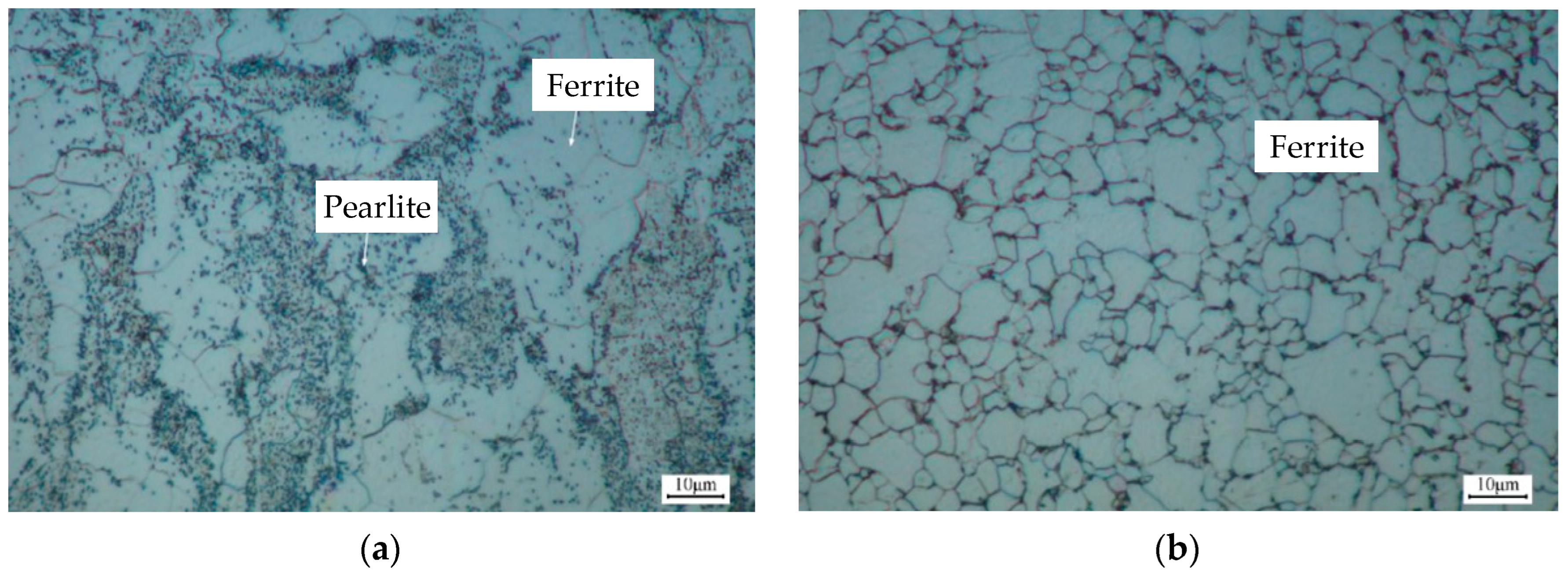
Figure 1. Microstructures of (a) B1500HS and (b) B340LA high-strength steels.
Metals 15 00393 g001
Figure 2. IPG fiber laser welding machine and welding jig.
Metals 15 00393 g002
Figure 3. (a) Testing machine and (b) tensile specimen dimensions (mm).
Metals 15 00393 g003
Figure 4. The macroscopic surface quality of different weld joints: (a) complete fusion, (b) incomplete fusion, (c) welding discontinuity, and (d) porosity defect.
Metals 15 00393 g004
Figure 5. Microstructure of the (a) weld joint and (b) fusion zone in TWBs.
Metals 15 00393 g005
Figure 6. Metallographic structure of the CGZ, (a) FGZ, and (b) IRZ in the HAZ of B1500HS.
Metals 15 00393 g006
Figure 7. Metallographic structure of the FGZ in the HAZ of B340LA.
Metals 15 00393 g007
Figure 8. The hardness distribution of the weld joint under different laser welding parameters.
Metals 15 00393 g008
Figure 9. Metallographs of the welded joints under different laser welding parameters: (a) 1500 W-25 mm/s, (b) 2000 W-25 mm/s, (c) 2500 W-25 mm/s, (d) 1500 W-30 mm/s, (e) 2000 W-30 mm/s, (f) 2500 W-30 mm/s, (g) 1500 W-35 mm/s, (h) 2000 W-35 mm/s, (i) 2500 W-35 mm/s.
Metals 15 00393 g009aMetals 15 00393 g009b
Figure 10. Metallographs of welded joint with the same heat input parameter combination: (a) 1500 W-15 mm/s, (b) 2000 W-20 mm/s, (c) 2500 W-25 mm/s.
Metals 15 00393 g010
Figure 11. The true stress–strain curves of the base metals.
Metals 15 00393 g011
Figure 12. The true stress–strain curves of the welded joints in TWBs under different laser welding parameters: (a) 25 mm/s, (b) 30 mm/s, (c) 35 mm/s.
Metals 15 00393 g012
Figure 13. Optimal welding parameter range for high-quality welds.
Metals 15 00393 g013
Figure 14. (a) Bend-forming tests and (b) finite element modeling.
Metals 15 00393 g014
Figure 15. The hat-shaped parts under different laser welding parameters.
Metals 15 00393 g015
Figure 16. The springback angles of the sidewall α 1 and flange α 2 .
Metals 15 00393 g016
Figure 17. Bending simulation results under different laser welding parameters: (a) 1500 W-25 mm/s, (b) 2000 W-25 mm/s, (c) 2500 W-25 mm/s, (d) 1500 W-30 mm/s, (e) 2000 W-30 mm/s, (f) 2500 W-30 mm/s, (g) 1500 W-35 mm/s, (h) 2000 W-35 mm/s, (i) 2500 W-35 mm/s.
Metals 15 00393 g017
Figure 18. Optimal welding parameter range for high-quality formed components.
Metals 15 00393 g018
Table 1. Chemical compositions of B1500HS steel (wt%). Adapted from Ref. [23].
CSiMnAlBSPCrNiFe
0.230.251.350.0460.00260.0020.020.170.016Bal
Table 2. Chemical compositions of B340LA steel (wt%). Adapted with permission from Ref. [24]. 2025 Elsevier.
CSiMnPSAlFe
0.0720.0360.780.0230.01150.048Bal
Table 3. Parameters for laser welding experiments.
Test Num.Laser Power/(W)Welding Speed/(mm/s)
1150015
2150025
3150030
4150035
5200020
6200025
7200030
8200035
9250025
10250030
11250035
12300030
Table 4. Weld quality of welds under different parameters.
Test
Num.
Laser Power
/W
Welding Speed
/(mm/s)
Macroscopic
Surface Quality
1150015complete fusion *
2150025complete fusion
3150030complete fusion
4150035incomplete fusion *
5200020complete fusion
6200025complete fusion
7200030complete fusion
8200035welding discontinuity
9250025complete fusion
10250030complete fusion
11250035complete fusion
12300030porosity defect
* Complete fusion: The fusion zone fully penetrates the base material thickness (1.2 mm), with no visible welding defects at the interface. Incomplete fusion: Penetration depth < 1.2 mm.
Table 5. Young’s modulus of TWBs.
Young’s Modulus/GPaB1500HSB340LAWeld Seam
-212212215
Table 6. The springback angles of the hat-shaped parts.
Test
Num.
laser Welding
Parameters
α1
α2
11500 W-25 mm/s2.10°3.32°
21500 W-30 mm/s1.99°3.13°
31500 W-35 mm/s1.82°3.02°
42000 W-25 mm/s2.48°4.01°
52000 W-30 mm/s2.41°3.99°
62000 W-35 mm/s2.36°4.01°
72500 W-25 mm/s3.10°4.37°
82500 W-30 mm/s2.71°3.98°
92500 W-35 mm/s2.98°4.12°
Table 7. Forming quality of TWBs under different parameters.
Test
Num.
Laser Power
/W
Welding Speed
/(mm/s)
Macroscopic
Surface Quality
Forming Quality of TWBs
1150015complete fusionforming defect *
2150025complete fusionforming defect
3150030complete fusionforming defect
4150035incomplete fusion\
5200020complete fusionforming defect
6200025complete fusionforming defect
7200030complete fusiongood formation *
8200035welding discontinuity\
9250025complete fusionforming defect
10250030complete fusiongood formation
11250035complete fusionforming defect
12300030porosity defect\
* Good formation: No visible cracks on the component surface, and the springback angle α 1 and α 2 deviation from their respective mean values are <11%; Forming defect: Presence of macroscopic cracks or springback deviation ≥ 11%.
Disclaimer/Publisher’s Note: The statements, opinions and data contained in all publications are solely those of the individual author(s) and contributor(s) and not of MDPI and/or the editor(s). MDPI and/or the editor(s) disclaim responsibility for any injury to people or property resulting from any ideas, methods, instructions or products referred to in the content.