Abstract
The chemical composition of FeCrAl alloy significantly influences its thermal-mechanical as well as anti-corrosive properties. This study investigates the impact of silicon and yttrium additions on the thermal-mechanical properties and high-temperature oxidation resistance of FeCrAl alloy. The results indicate that thermal conductivity gradually decreases with the incorporation of Y or Si into the lattice, whereas the mechanical strength of the alloy can be enhanced through the addition of Y. A trace amount of Y can improve the alloy’s high-temperature oxidation resistance by mitigating the spallation of the surface oxidation film and promoting the growth of the film, characterized by heterogeneous chemical composition and microstructure. It is observed that Y possesses a higher charge density than FeCrAl, suggesting that Y can lose electrons more readily than other elements, which implies a reduction in oxygen diffusion.
1. Introduction
Current and future advanced energy systems require structural materials that can withstand high-temperature environments. The materials are required to maintain both mechanical strength and corrosion resistance at high temperatures while also having high thermal conductivity and low expansion rates [1]. Common high-temperature structural materials include intermetallic compounds and high-temperature ceramics, such as Ti-Al alloys, Ni-Al, and Fe-Al, which have been identified to maintain robust reliability in the aerospace and automotive industries [2]. Additionally, high-temperature ceramics, including silicon and carbide, can also be identified as promising candidate materials in the aerospace and automotive industries [2].
Among these structural materials, Fe-Al alloy has been chosen as an ideal high-temperature structural material due to its robust oxidation resistance at high temperatures, as well as its good mechanical properties and low density [3]. The addition of the Cr element can further increase the oxidation resistance of the Fe-Al alloy and improve its mechanical and electrochemical properties, which makes it an ideal substitution material for stainless steel as a high-temperature alloy material at 773~873 K [4,5,6].
FeCrAl alloys are long recognized to have robust performance in turbo systems, boiling water tanks, heating elements, etc., due to their ready formation of surface oxide film at high temperatures [7]. The feasible formation of Cr2O3 at low oxidation temperatures will lose its passivation capability at elevated temperatures [8]. Therefore, the high-temperature anti-oxidative capacity is highly dependent on the formation of metal-stable Al2O3 at high temperatures in order to compensate for the loss of Cr2O3, which induces the superior anti-oxidative capacity for FeCrAl alloy [9]. The properties of the surface oxide film are crucial for the corresponding performance of the materials, which is highly dependent on its chemical composition, as confirmed by previous research [9,10]. Weisenburger et al. [11] showed that model FeCrAl alloys containing 12.5 wt.% Cr and 6 wt.% Al were able to form thin protective alumina layers in the temperature interval of 400–600 °C. It is difficult to simultaneously achieve high mechanical strength and oxidation resistance for FeCrAl alloy. Previous research has optimized the chemical composition of FeCrAl alloy (Fe-13Cr-6Al) by balancing the mechanical strength and oxidation resistance under the LOCA scenario [12,13].
However, the uneven growth of the oxidation film leads to the premature spalling and breakdown of these denseα-Al2O3 scales during high-temperature oxidation, particularly upon large fluctuations in temperature, limiting the practical application of FeCrAl alloys [14]. Rare earth elements (REs) such as Y, La, and Ce have long been considered active elements that can be used to reduce film spallation as well as increase the high-temperature affinity of film [15,16]. Among these elements, Y has been widely used as an active addition to suppress the oxidation film’s growth rate and reduce film spallation [17]. Qi’s research pointed out that the addition of Y promotes the formation of the Al2O3 layer and stabilizes its structure, which helps to reduce the spalling of oxides [13]. More in-depth research has been conducted on the effect of Y on the oxidation properties of FeCrAl alloy. Riffrard’s research shows that the addition of Y will increase the oxidation rate in the initial oxidation stage, followed by reducing the on-site oxidation rate due to the gradual formation of a stable oxide film [18]. Ramanarayanan’s research further confirmed that Y doping can significantly improve the high-temperature oxidation resistance of FeCrAl alloy, especially when an Al2O3 film is formed [19]. Meanwhile, the lowest oxidation weight gain being obtained by incorporating Y into the FeCrAl matrix can be explained by the formation of secondary Y2O3 or the ternary crystalline phase of Y3Al5O12 [10], reducing the film spallation and increasing the film quality. Although the addition of Y can enhance the oxidation resistance of the alloy, it has a rare positive effect on the thermal-mechanical property based on the previous report [20]. To some extent, the addition of Y or Y2O3 can reduce the Young’s modulus of the alloy by making the alloy more brittle at high temperatures [20]. Therefore, the high-temperature application of the alloy needs to thoroughly balance the thermal-mechanical behavior and anti-oxidation behavior. However, few previous studies have provided a deeply insightful and convincing mechanism that can clearly explain the role of additive elements in simultaneously enhancing thermal-mechanical properties and oxidation resistance, especially under high-temperature oxidation conditions.
On the other hand, the effect of the concentration of eutectic elements on the thermal and mechanical properties of the FeCrAl alloys has been further studied, aside from its oxidation resistance. Although the addition of Al can significantly enhance the formation of oxidation film, it can lead to the fast phase transition to BCC, which results in a high brittle property [12]. The Cr ratio of higher than 21 wt.% can lead to the phase segregation of α-phase [21], while the high-temperature mechanical performance can be enhanced by the addition of Mo (0–3 wt.%), leading to the formation of a secondary Laves phase [22]. However, it was pointed out that the addition of Mo can reduce the mechanical performance of the surface oxidation film, leading to premature spallation and cracking of the oxidation film [10]. From now on, the effect of Cr and Al on the alloy’s thermal-mechanical and anti-oxidation properties has been deeply studied, with the Cr and Al ratio being further optimized. However, the overall effect of trace addition elements, including Y, Si, or Nb, on the physical-chemical properties of the alloy has not been fully appraised.
Although the positive effect of Y on the anti-oxidation property of the FeCrAl alloys has been widely studied, there is a lack of systematic understanding of the thermal-mechanical properties of Y-doped FeCrAl alloy. Whether the Y-doped alloy exhibits simultaneously robust thermal and mechanical performance along with the anti-oxidation performance remained unknown. In the current study, the FeCrAl alloys with variable Si and Y addition have been successfully fabricated, with their microstructure evolution being further characterized. The thermal-mechanical properties of the alloys have been further evaluated by measuring the temperature-dependent thermal conductivities, stress-strain curves, and friction-wear behavior. The anti-oxidative behavior of the alloys was studied by conducting the on-site high-temperature oxidation test subjected to the ambient atmosphere. The microstructure evolution of the alloy before and after oxidation was characterized by Scanning Electron Microscopy (SEM) and Scanning Transmission Electron Microscopy (STEM), while the on-site oxidation weight gain was further determined. The effect of rare earth Yittrium on the oxide film formation was studied by the first principal calculation as well.
2. Materials and Methods
2.1. Materials
The FeCrAl alloy (with Si and Y addition) with detailed chemical compositions was manufactured by vacuum induction melting (VIM) of pure Fe (99.50 wt.%), Cr (99.00 wt.%), Al (99.60 wt.%), Si (99.90 wt.%), and Y (99.90 wt.%) at a temperature of 1150 °C, followed by high-temperature homogenization for 3 h under 1000 °C before hot rolling into sample slices with a thickness of 16 mm at 800 °C. The precast ingots were further machined into thin slices with a length and width of around 10 mm, followed by thermal annealing at 1000 °C for 3 h before polishing for further testing. The chemical compositions of the alloy can be determined by an inductively coupled plasma optical emission spectrometer (ICP-OES) (ICAP-6300, Thermal Fisher Scientific, Waltham, MA, USA), while the residual carbon content was measured by a carbon analyzer (HW2000B, Joinstars, Hangzhou, China) as well. The chemical compositions of these alloys based on the ICP-MS are listed in Table 1.

Table 1.
Chemical composition of the six FeCrAl alloys tested herein.
2.2. Methods
The surface microstructure evolution of the as-synthesized alloy pellets was further characterized by Scanning Electron Microscopy (SEM) (TESCAN LYRA3 GM, Warrendale, PA, USA), with the corresponding elemental analysis being achieved by elemental dispersive spectroscopy (EDS). The samples were chemically etched with acetic acid (70%) before being subject to grain size and grain boundary determination. The crystalline structure of the as-synthesized alloy was further characterized by X-ray diffraction (XRD) (PANalytical B.V., Westborough, MA, USA). The cross-section morphology evolution, as well as the elemental distribution of the sample alloy post-high-temperature on-site oxidation, can be analyzed by SEM-EDS. The nanoscale structural evolution of the sample coupon post-oxidation can be further evaluated by STEM (TITAN 200, FEI, Hillsboro, OR, USA), with the sample lamella being prepared by the focused ion beam.
The mechanical performance of the fabricated alloys was further studied by plotting the stress-strain curves via a universal testing machine (UTM, SUNS, Shenzhen, China), with the corresponding tensile stress, fracture stress, and elongation rate being calculated. The uniaxial tensile rate of the sample was set to be 1 mm/min. The temperature was controlled by a heating chamber with an aluminum oxide ceramic insulator surrounding it. The tensile tests were carried out three times for each sample under both room temperature and 400 °C.
The coefficient of friction (COF) and wear rate of the FeCrAl alloy at both room temperature and 400 °C were further studied by carrying out the friction and wear test (Anton Paar TRB, Graz, Austria). The test selected Φ6 mm Al2O3 balls and Φ26 mm × 8 mm TC4 alloy cylinder distribution as the upper and lower samples. The upper specimen dual ball is fixed to the cantilever of the testing machine through a hollow pin tube, and the TC4 alloy cylinder is fixed to the moving sub-frame of the testing machine through a clamp. Before the test, the lower sample was ground, polished, cleaned, and dried; the upper and lower samples were cleaned with alcohol to ensure that the two contact surfaces were smooth and to avoid distortion of the wear data caused by different initial contact interface roughness, impurities, etc.
The thermal conductivity of the as-fabricated sample coupons was evaluated by a laser flash analyzer (TG309, NETZCH, Exton, PA, USA). The sample pellets were sized down to a round pellet with a diameter of Φ12 mm and a thickness of around 1.5 mm. The sample pellets were deeply polished and then sprayed with graphite paste before the test. The thermal diffusivity of the sample pellets was measured, and the corresponding temperature-dependent thermal conductivity was further determined by the following formula:
The k stands for thermal conductivity, which can be calculated by the as-measured thermal diffusivity (), density, and thermal capacity (C).
The first principal calculation was introduced to a fundamental understanding of the interfacial effect of oxygen/metallic surface in order to reveal the oxidation pathway. A molecular model with 64 atoms (thickness of 25 Å), evenly distributed into four layers with a corresponding lattice constant of a = 11.5 Å, b = 11.5 Å, and c = 29.3 Å. The first calculation modeling was carried out by VASP, with a cutting energy of 400 eV; the k-point regarding the Boullinou zone is being set as 4 × 4 × 1, with calculation following the (001) lattice plane.
The distance between the oxygen atom and the FeCrAl alloy has a strong impact on its oxidation process. Therefore, the oxygen adsorption mechanism on the alloy was revealed by calculating the system energy based on the different oxygen-alloy distances following the (100) crystalline plane (Figure 1). The oxygen atom moved toward the red arrow, as denoted in Figure 2. Analyses of total energy, adsorption energy, and charge transfer were conducted in order to evaluate the stability and interaction of oxygen with the alloy. The adsorption energy, which quantifies the strength of the bond between oxygen and the surface, is calculated using the following formula:
where is the total energy of the system after oxygen adsorption, is the energy of the clean surface, and is the energy of the isolated oxygen molecule. represents the adsorption energy, with a negative value indicating favorable adsorption and a positive value indicating repulsion. However, it should be noted that the adsorption energy includes both the oxidative binding energy and the crystal distortion potential energy.
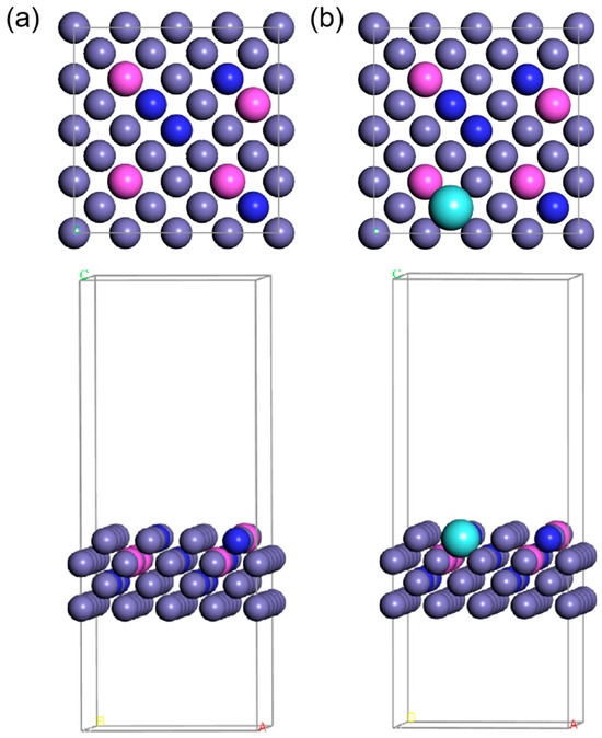
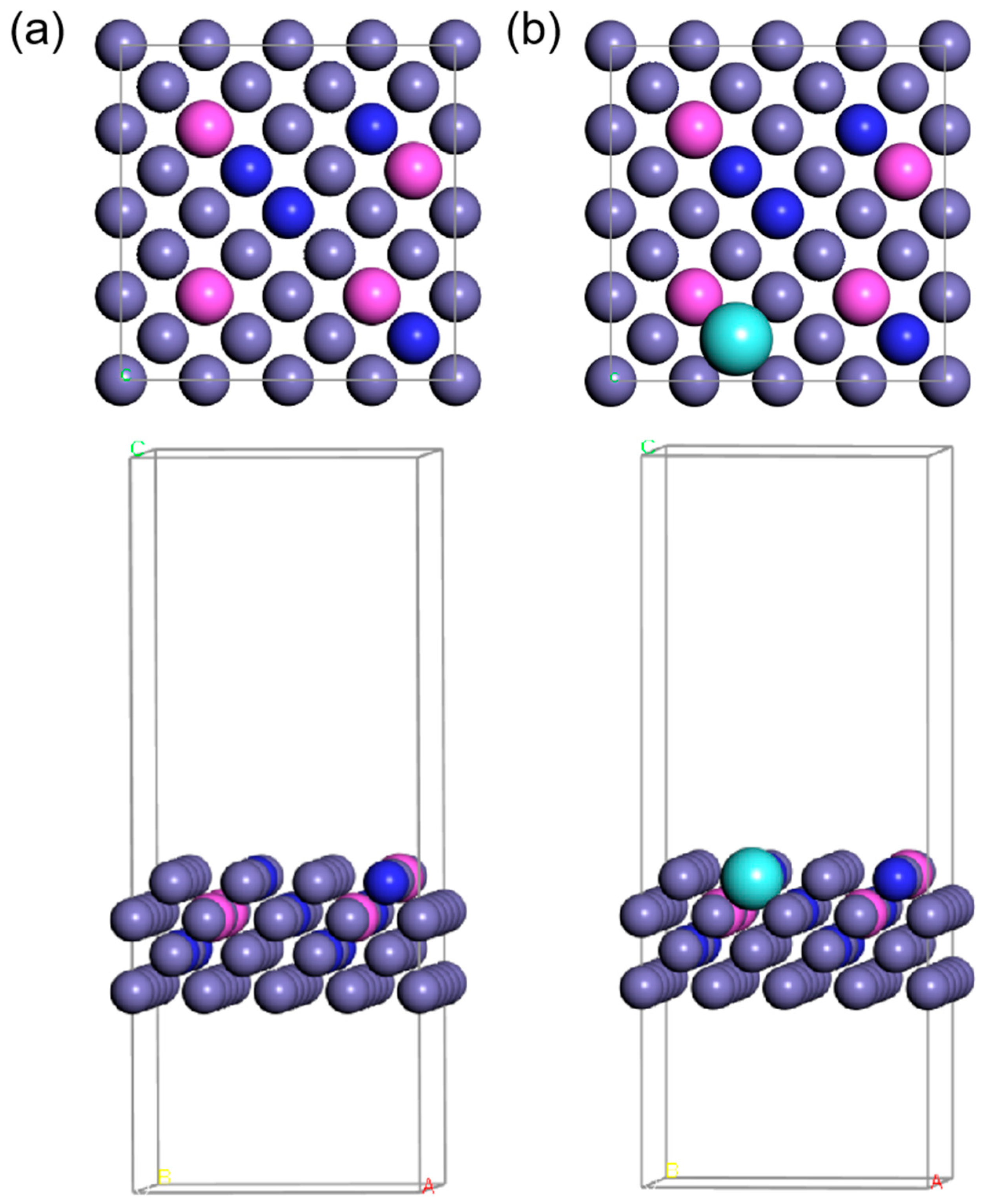
Figure 1.
The top view and side view of the atomic arrangement are (a) FeCrAl and (b) FeCrAlY. Purple, pink, blue, and cyan balls stand for Fe, Al, Cr, and Y, respectively.
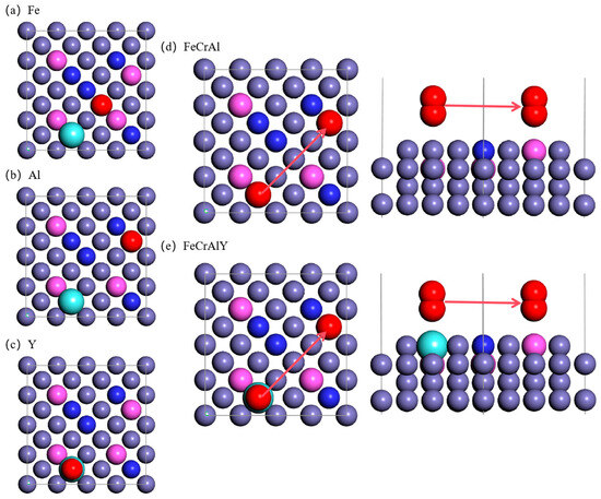
Figure 2.
Top view of the atomic model for the oxygen adsorption on the FeCrAl. (a) oxygen atom right above the Fe atom, (b) oxygen atom right above the Al atom, (c) oxygen atom right above the Y atom, (d) top view of oxygen diffusion at the same height level for FeCrAl, (e) top view of oxygen diffusion at the same height level for FeCrAlY.
3. Results and Discussion
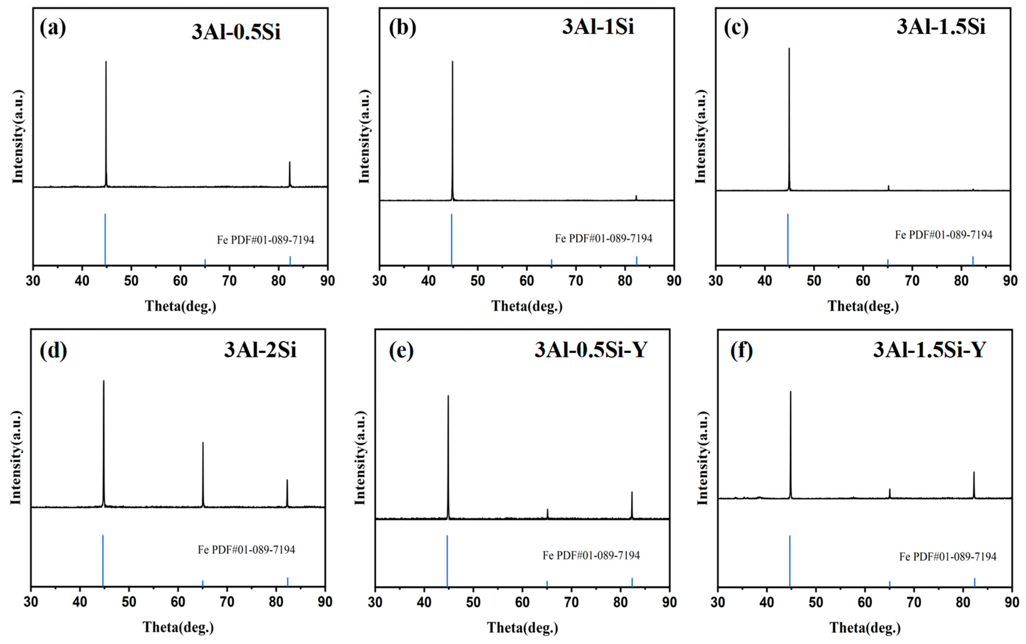
The crystalline structure of the as-fabricated alloys was tested with the corresponding XRD profiles indicated in Figure 3. The major crystalline phases for these sample coupons can be indexed as alpha-Fe phase [Fe PDF#01-089-7194] without a secondary phase being detected, consistent with previous research [13]. The lattice constant derived from the Rietvald peak refinement can be further indicated in Figure 3, which suggests a constant lattice parameter around 2.8662 Å. The lattice constants did not show a large discrepancy by increasing the Si addition. The addition of Y leads to the reduction in the lattice constant; specifically, the lattice constant reduces from 2.8662 Å to 2.856 Å by the Y incorporation, which probably can be attributed to the small ionic radii size of Y compared to other metallic elements.
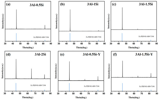
Figure 3.
XRD profile of the as-fabricated FeCrAl alloys.
The microstructure and average grain sizes of the FeCrAl alloys with and without the Y addition were denoted in Figure 4, with the average grain sizes of the sample pellets being around 20–40 μm. Specifically, the average grain sizes for these sample pellets are 27 μm, 38 μm, 32 μm, and 34 μm for 3Al-0.5Si, 3Al-1Si, 3Al-1.5Si, and 3Al-0.5Si-Y, respectively. A large proportion of the grain sizes fall within the range of 20–50 μm, with only a few grains with size below either below 20 μm or above 50 μm. Similar average grain size and grain size distribution can be demonstrated in our previous research [12,13] with the same casting process. The as-cast FeCrAlMoY alloys herein are higher than the APMT FeCrAl alloy with a general grain size of 8.8 μm due to the different preparation methods [23]. The average grain sizes faced increase with the addition of Si and decrease by further increasing the Si ratio. The addition of Y does not have a significant impact on the grain growth, as denoted in Figure 4. The surface of the sample alloys featured a columnar grain structure without manifest open pores, suggesting the successful fabrication of the alloy with high theoretical density.
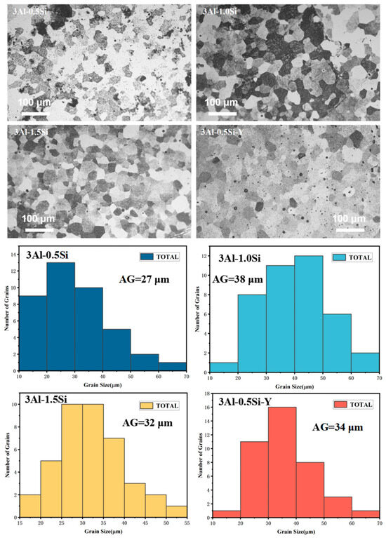
Figure 4.
The surface microstructure and corresponding crystalline grain distribution for the as-fabricated sample alloys.
3.1. Thermal Conductivity
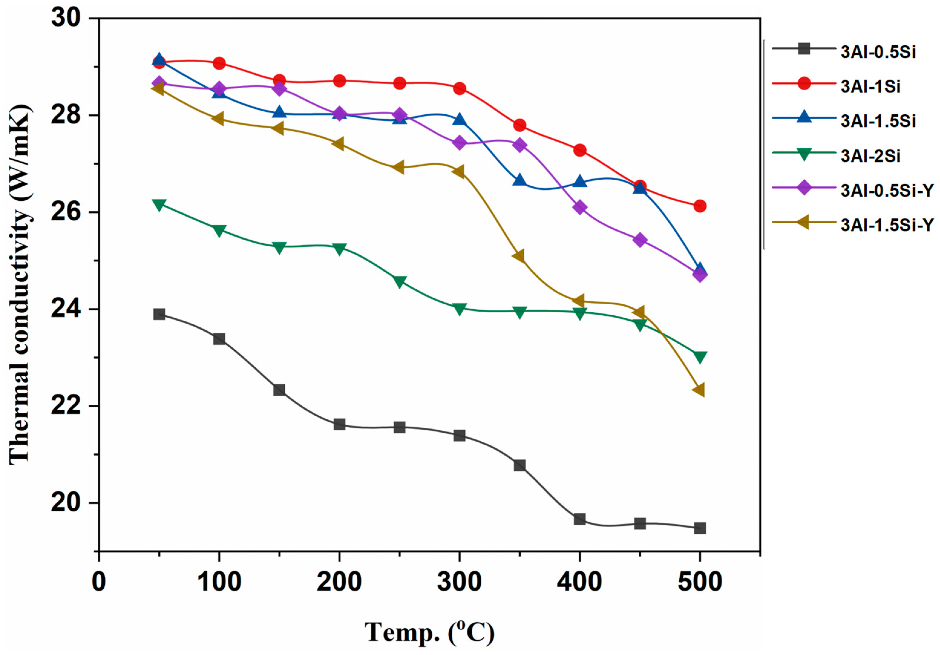
The thermal conductivity of the as-fabricated alloys was further studied and subjected to elevated temperature from room temperature to 500 °C, as denoted in Figure 5. The thermal conductivities gradually reduce with temperature due to the high thermal radiation effect at high temperatures. The alloys exhibit high thermal conductivities ranging from 20 to 30 W/mK, with the highest thermal conductivity coming to 3Al-1Si. The thermal conductivities for the fabricated alloys herein are significantly higher than the Kanthal APMT and C06M FeCrAl alloy, with typical thermal conductivities around 16 W/mK [24]. The increases in Al content will lead to an increase in thermal conductivity, with the highest thermal conductivity no more than 20 W/mk [24,25]. Therefore, the as-fabricated Fe-Cr-Al-Si-Y alloys enjoy higher thermal conductivity than monolithic FeCrAl alloys, which is beneficial for high-temperature applications. The addition of Si reduces the thermal conductivity of the alloy by increasing the lattice disorder through short-term atomic interaction. The highest thermal conductivities can be seen for the 3Al-0.5Si, followed by 3Al-0.5Si-Y, compared to the alloys with higher Si ratios. In addition, the addition of Y has a strong impact on high-temperature thermal conductivity by reducing thermal conductivity in a high-temperature regime.
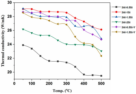
Figure 5.
Thermal conductivities of the as-fabricated alloys.
3.2. Mechanical Behavior
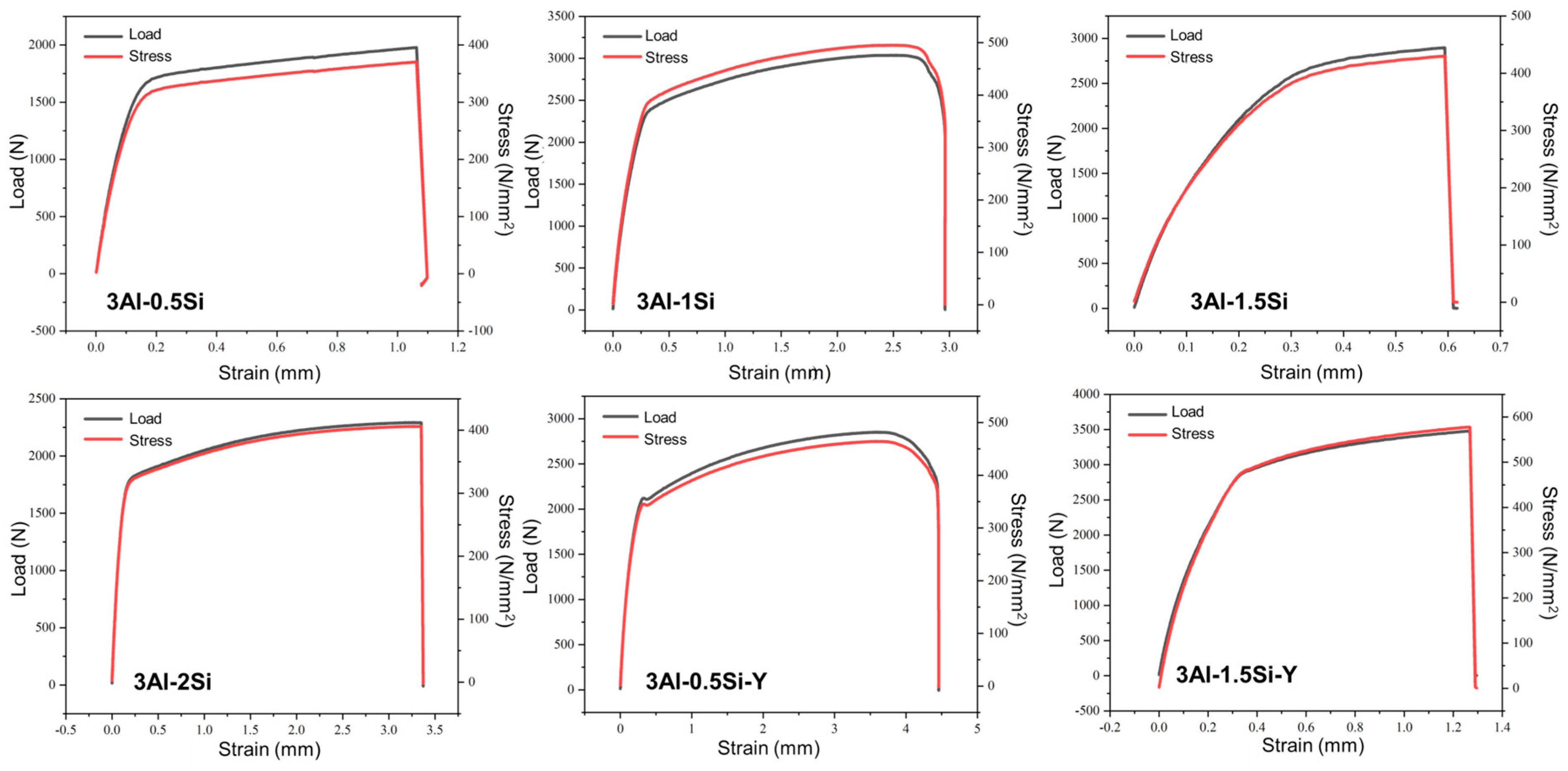
The as-measured yield stress and tensile stress first increase with the Si ratio and then decrease at a high Si ratio of 3Al-2Si, as denoted in Figure 6. The fracture elongation ratio also faces an increase-to-decrease transition since the high amount of Si addition significantly decreases the fracture toughness of the alloy by making the alloy more brittle. It is suggested that the addition of Si refines the alloys’ crystal grains and the crystalline structure units (packets, blocks, and laths). However, the higher amount of Si leads to the formation of Si-enriched precipitation, resulting in a reduction in mechanical strength [26]. The yield stress and tensile stress can be further enhanced through the addition of Y, which can stabilize the alloy under high temperatures. The addition of Si and Y in the improvement of the tensile stress of FeCrAl alloy can be further confirmed by previous research. The highest yield stress and tensile stress of around 3000 and 3500 can be seen for 3Al-1.5Si-Y, with the corresponding breakage engineering strain of 0.5 mm. The addition of Y leads to the increase in breakage elongation rate as denoted in the comparison of strain within 3Al-0.5Si and 3Al-0.5Si-Y and 3Al-1.5Si and 3Al-1.5Si-Y, suggesting the potential mechanism transition from plastic deformation to elastic deformation. According to previous research, the addition of Y can significantly increase the high-temperature oxidation resistance as well as the mechanical strength by reducing the plastic deformation ability. Therefore, the Y addition in the alloy should be subsequently optimized in order to balance the oxidation resistance and thermal-mechanical properties. Similar behavior of Y in enhancing the mechanical behavior of FeCrAl alloy can also be observed in previous research [27]. The current alloy with Si and Y addition enjoys higher mechanical properties as compared to Fe-20Cr-5Al, with a corresponding engineering strain of 0.3 mm, lower than the alloy studied herein, suggesting the synergistic effect of Si and Y in improving the alloy’s mechanical performance, especially at high temperature [28].
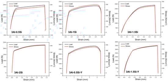
Figure 6.
Stress–strain curves for the FeCrAlSi and FeCrAlSiY alloys at room temperature.
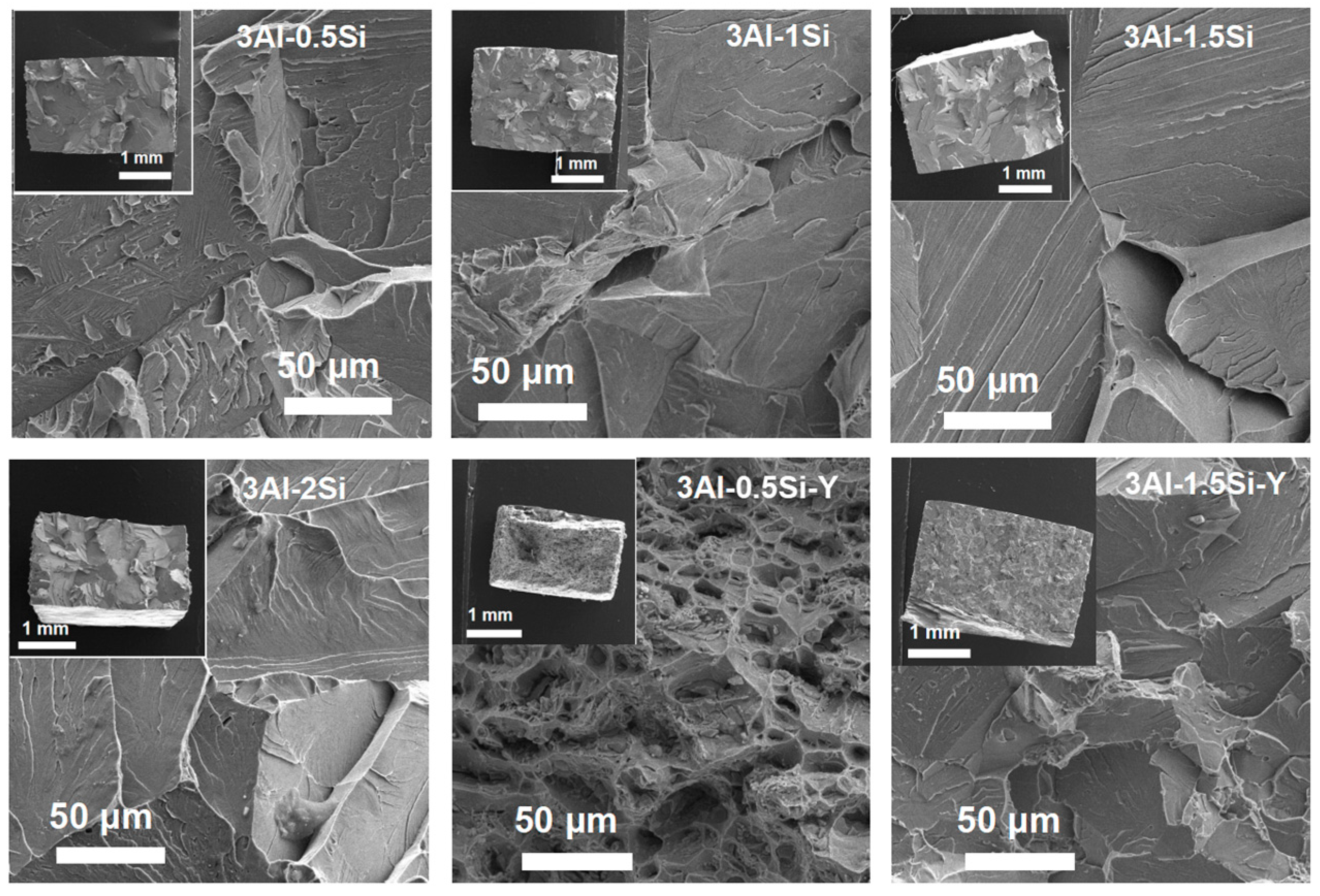
The fracture cross-section of the sample coupon post-mechanical tests was further characterized in order to elucidate the deforming mechanism by SEM, as denoted in Figure 7. The ductile fracture surface of the as-tested sample coupons denotes significant breakage on the crystal grain without manifest micro-voids and dimples, suggesting the strong mechanical strength of the grain boundary. On the other hand, a large area of grain pullout can be seen for the alloys with Y addition, suggesting that ductile fracture occurred. However, a high amount of Y incorporation results in the mechanism transition from ductile fracture to brittle fracture as the alloy crystal breaks apart during the stress-strain test, with the morphology of the fracture cross-section denoted in Figure 7.

Figure 7.
Microstructure of the cross-section of the sample coupons post stress–strain tests.
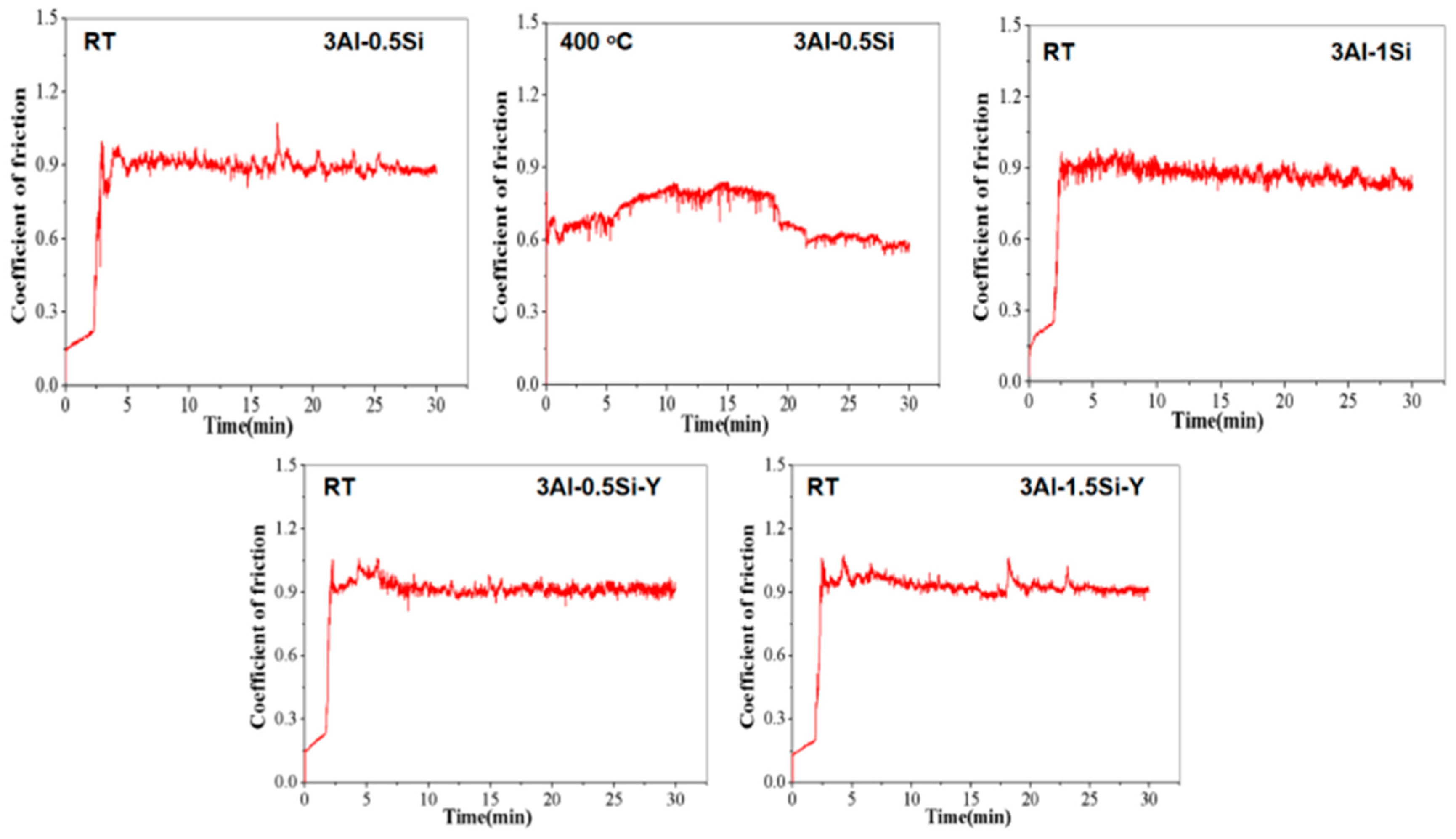
The coefficient of friction (COF) and wear rate of the FeCrAl alloy at both room temperature and 400 °C are presented in Figure 8 and Figure 9. It is found that the incorporation of Y slightly enhanced the CoF to above 0.9, suggesting a higher friction resistance compared to the one without Y addition. The addition of Si has barely any effect on the material toughness, as evidenced by the time-dependent CoF curves. The CoF curve typically progresses through two stages as denoted herein: (1) in the initial stage, the sharp increases in the CoF can be seen, which can be attributed to the direct contact with the matrix, and the typical two-body contact causes a sharp increase in friction coefficient; (2) in the stabilization stage, the CoF value is stable, and the friction experiment enters a stable period. A slight decrease in the COF can be observed in the 5-minute friction test, which can be attributed to the lubricating effect resulting from the contact between the friction debris and the matrix, causing the so-called three-body contact model as denoted in the previous research [28]. Significant reduction in the COF can be observed at higher temperatures (400 °C) compared to room temperature for 3Al-0.5Si, which is consistent with the Inconel 718 alloy [29]. The temperature-dependent reduction in the COF, representing the reduction in friction resistance, can be attributed to the reduction in the mechanical strength, leading to the softer of the alloy at elevated temperatures [29].
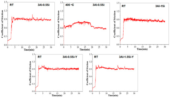
Figure 8.
The coefficient of frictional curves for FeCrAl alloys during the tribological tests at room temperature and 400 °C.
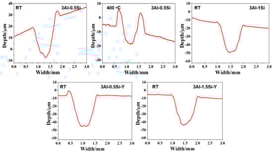
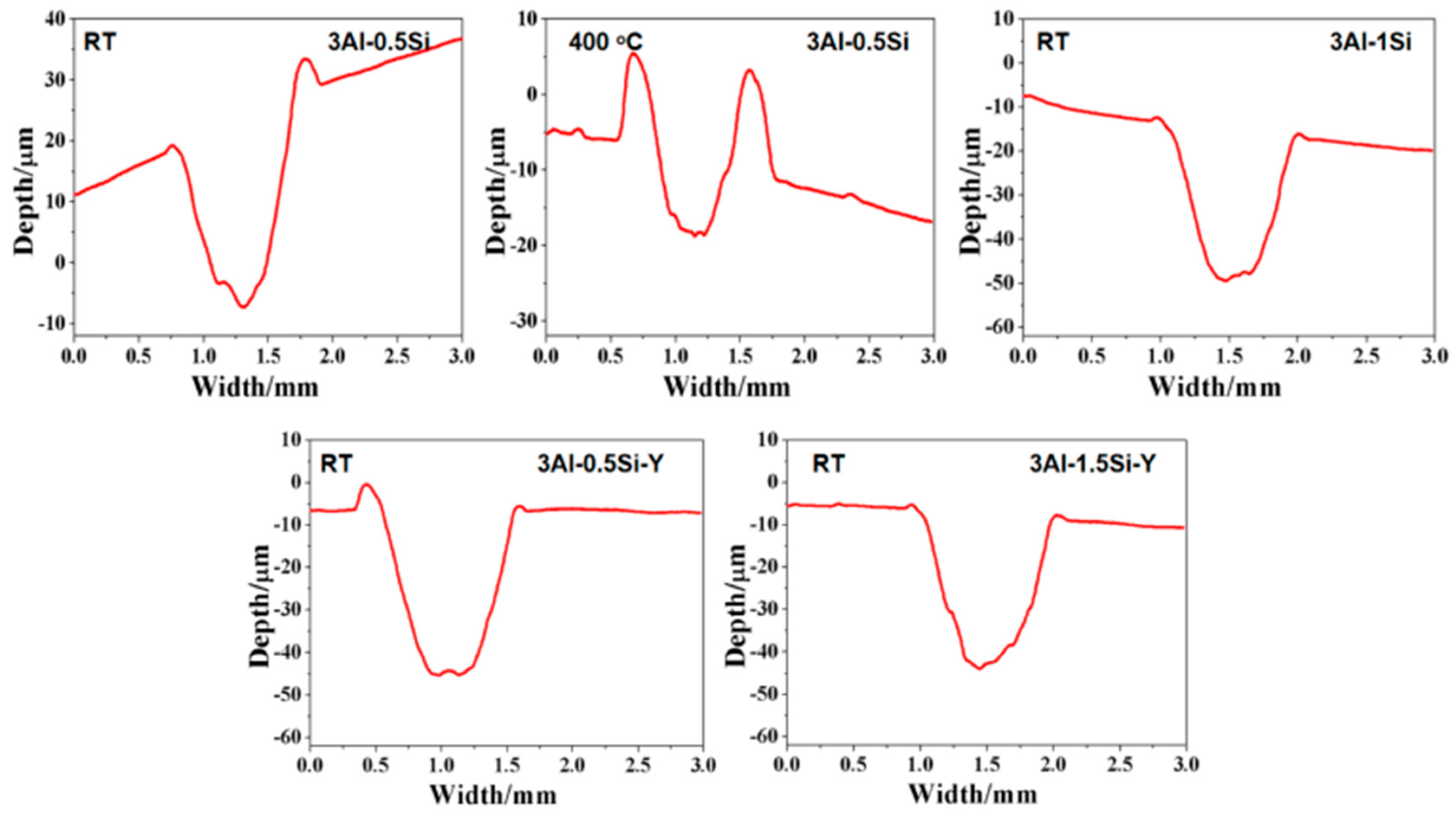
Figure 9.
2D profile of worn surface for FeCrAl alloys at room temperature and 400 °C.
The 2D profile of the worn surface can further be denoted in Figure 8 and Figure 9, with the corresponding microstructure related to the damage zone being seen in Figure 10. Both depth and width are almost identical for the tested alloys at room temperature, suggesting the Y or Si does not have a manifest effect on its wear behavior. The width and depth show a significant increase for 3Al-0.5Si at elevated temperatures, suggesting temperature-dependent mechanical strength degradation at temperatures as high as 400 °C. The two depth peaks around 0.7 and 1.7 with different shapes indicated a distinguishable damage behavior of the alloy at elevated temperatures. At 400 °C, the main worn mechanism was abrasive wear, stripping, and oxidative wear; the wear debris remained on the alloy surface, resulting in the two peaks in the worn curve [30,31]. The wear surface is irregular, featuring uneven distribution and wear damage to tracks. Some areas have severe spalling, and other areas show the characteristics of abrasive wear, which leads to the dispersion of minute wear debris.

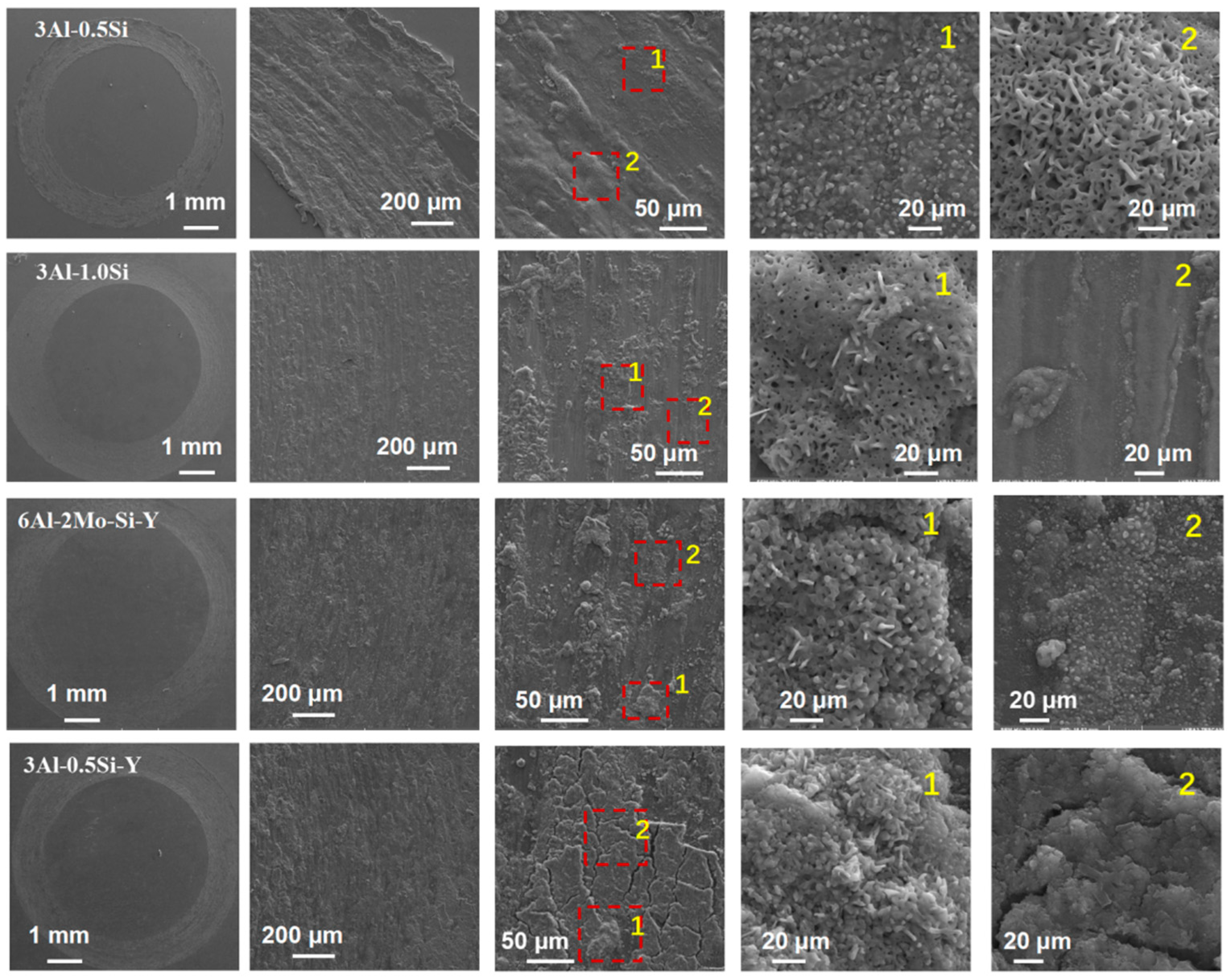
Figure 10.
Microstructure of the worn surface for the FeCrAl alloys.
3.3. Surface Alteration Behavior of FeCrAl Alloys Subjected to High-Temperature Oxidation
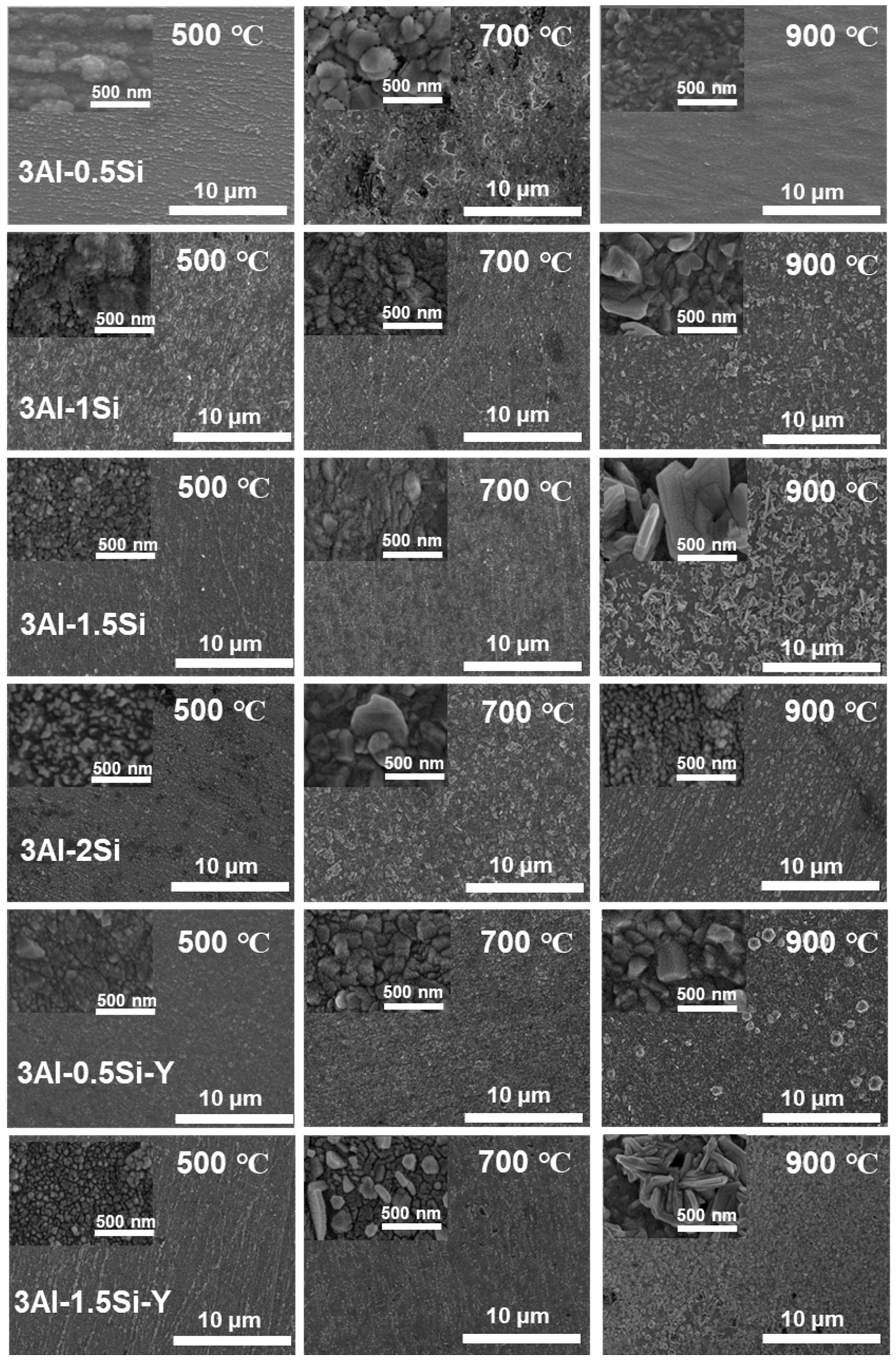
The on-site high-temperature oxidation behavior of the alloys subjected to elevated oxidation temperatures from 500 to 900 °C for 20 h was further studied, with the corresponding changes in surface morphology that can be seen in Figure 11. The surface oxidation of the alloys leads to the gradual growth of the surface oxidation film, which further results in the enhancement of the surface roughness. The grain growth of the oxidation film is thermodynamically driven, with the average grain size of the oxidation film gradually increasing from 500 °C to 900 °C, especially for the Y-doped FeCrAl alloys (3Al-0.5Si-Y and 3Al-1.5Si-Y). Specifically, the spherical grain of the oxidation film gradually transfers to equatorial or columnar grain at 900 °C, denoting the fast growth of the surface oxidation film. For example, the average grain size of 50 nm gradually increases to 500 nm from 500 °C to 900 °C (Figure 11). The surface roughness increases with the addition of Si, with the inhomogeneous growth of the oxidation particles randomly distributed on the sample surface, leading to the non-uniform microstructure of the film morphology. For comparison, the surface of Y-doped alloys was featured with a uniform morphology with homogeneous oxidation particles distributed. The large-scale morphology of the surface oxidation film without film convolution and defoliation can be seen for the Si- and Y-doped FeCrAl alloys. Therefore, the incorporation of Y can stabilize the growth of the surface oxidation film, leading to the reduction of film convolution and spallation.
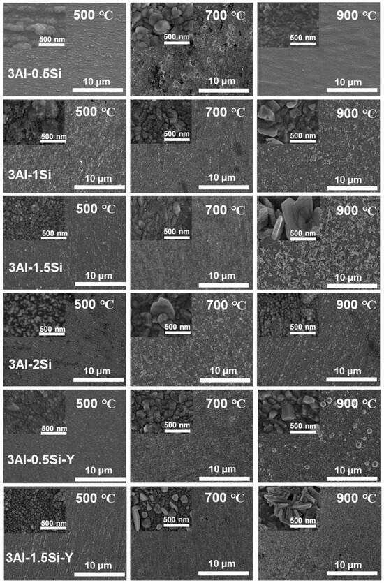
Figure 11.
Microstructure of the surface oxidation film morphology for the FeCrAl alloys subjected to different temperature ranges from 500 °C to 900 °C.
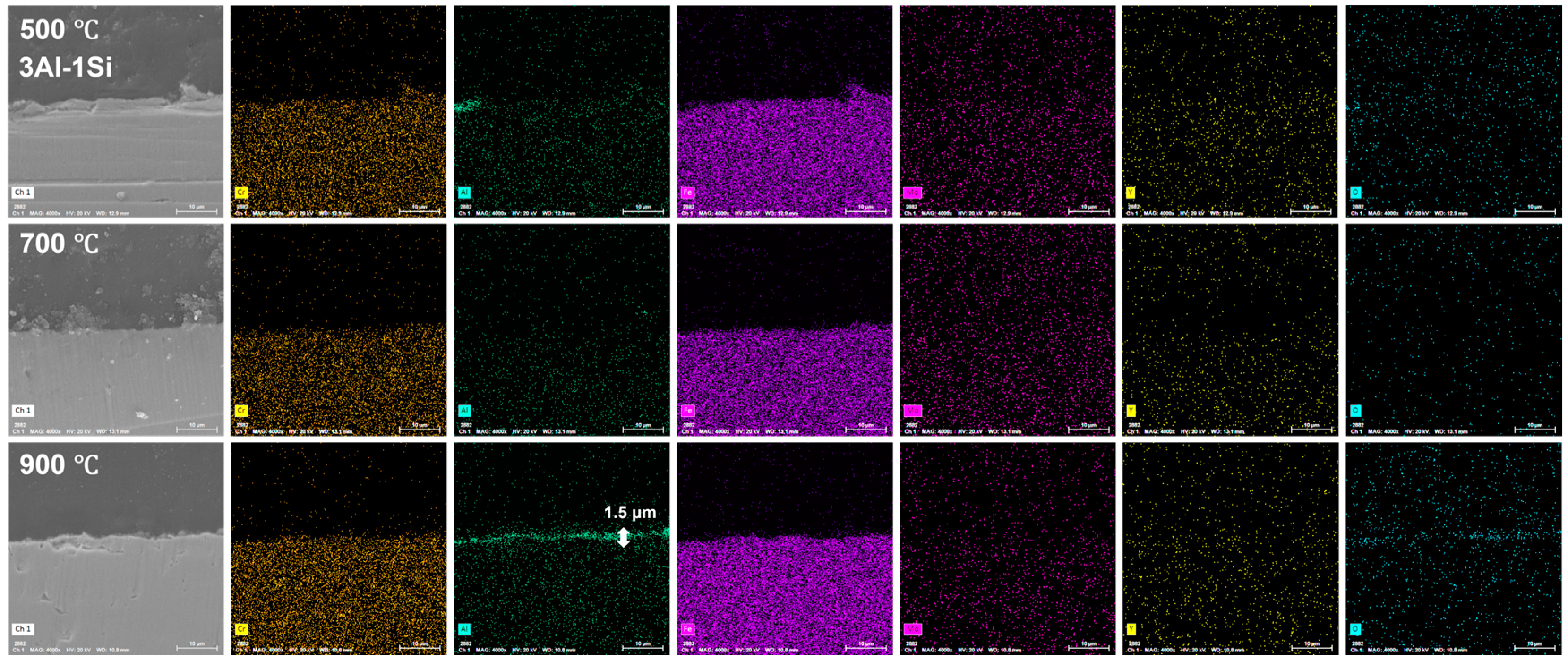
The surface oxidation film was Al-enriched at a temperature of 900 °C, with which thickness gradually increased from 1.5 μm to 3.5 μm and finally to 4 μm with the increases of Y ratios, demonstrating the functionality of Y on the acceleration of the oxidation film. The temperature-driven growth kinetics of the surface oxidation layer follows a parabolic model, suggesting the decreasing of the oxidation film formation via reducing the oxygen diffusion and penetration with the gradual formation of the oxidation film. The oxidation film is almost invisible at temperatures of 500 °C and 700 °C post 20 h oxidation, suggesting the temperature-dependent fast growth of the surface oxidation film. The temperature below 900 °C cannot trigger the fast growth of the surface oxidation film, which can be significantly accelerated by the temperature around 900 °C (Figure 12, Figure 13 and Figure 14).
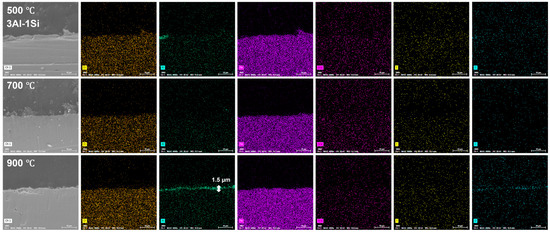
Figure 12.
Cross-section microstructure of the Fe-13Cr-3Al-1Si post elevated oxidation temperature and corresponding elemental mappings.
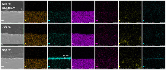
Figure 13.
Cross-section microstructure of the Fe-13Cr-3Al-1Si-Y post elevated oxidation temperature and corresponding elemental mappings.
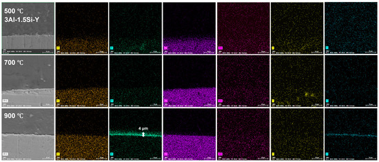
Figure 14.
Cross-section microstructure of the Fe-13Cr-3Al-1.5Si-Y post elevated oxidation temperature and corresponding elemental mappings.
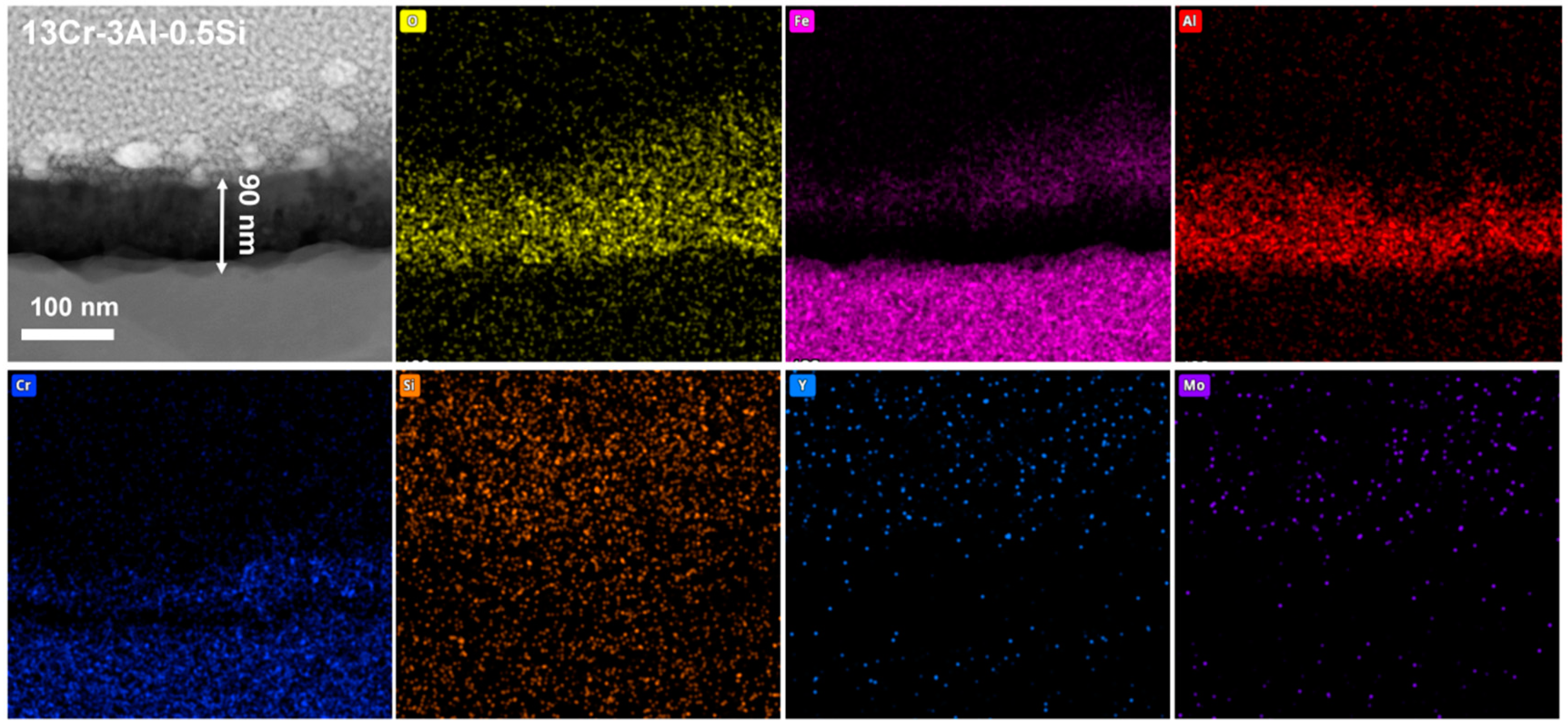
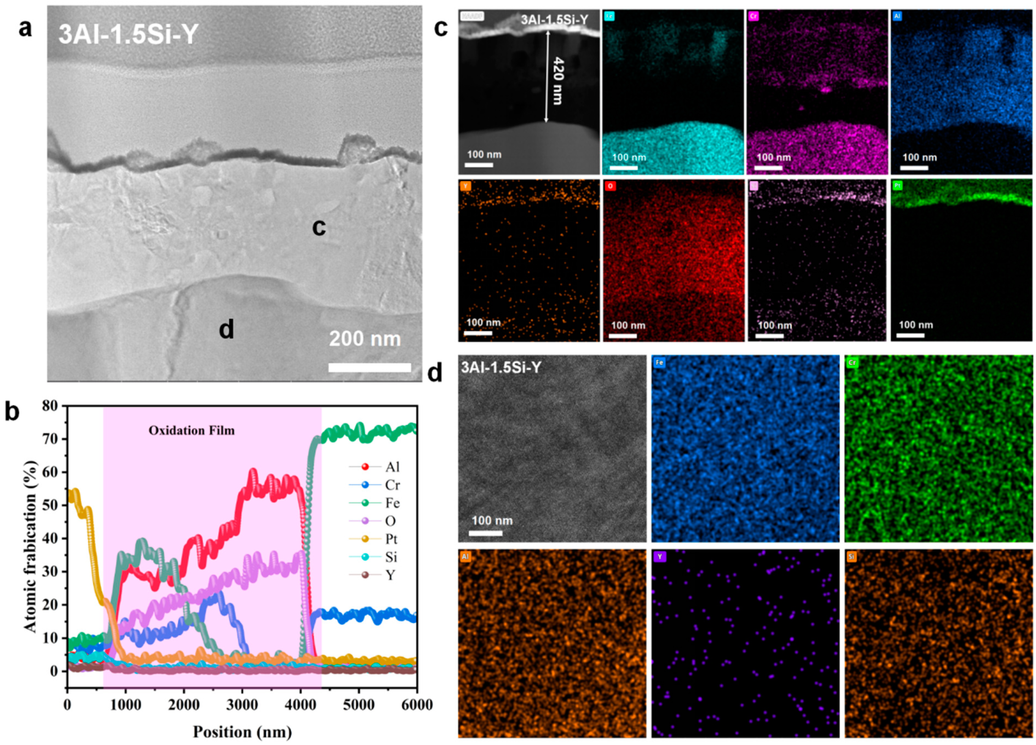
The nanoscale observation of the surface oxidation film, as well as the insightful understanding of the chemical composition of the oxidation film, can be further studied by the STEM as denoted in Figure 15, Figure 16 and Figure 17. Results indicate the heterogeneous property of the surface oxidation film with a triple-layer structure dominated, as denoted in the EDS mappings for both 13Cr-3Al-0.5Si and 13Cr-3Al-1.5Si-Y post 700 °C oxidation. Specifically, the top layer of the oxidation film is Fe-enriched with a thickness of around 80 nm for 13Cr-3Al-0.5Si, followed by a chromium-enriched oxidation layer (Figure 15). The addition of Y can further propagate the film growth, as evidenced by the surface oxidation layer with a thickness of around 420 nm for 13Cr-3Al-1.5Si-Y. The Al dominated the oxidation layer underneath the Fe- and Cr-enriched layer, with the thickness around 100 nm post 700 °C on-site oxidation for 13Cr-3Al-0.5Si. The top layer enriched with Fe can be seen with a thickness of around 50 nm, while the Cr-enriched layer with a thickness of around 50 nm can be seen in the middle region of the oxidation film to form a triple-layer structure. The Si and Mo signals are weak and approximately undetectable, as denoted by the elemental mappings, suggesting the indirect function of Si and Mo in the formation of oxidation film (Figure 15). A similar triple-layer structure can be seen for 13Cr-3Al-1.5Si-Y oxidized at 700 °C, as denoted in the elemental mappings in Figure 17, with the Fe, Cr, and Al-enriched layer staying on the top surface of the oxidation film. However, the thickness of the oxidation film for 13Cr-3Al-1.5Si-Y is higher than that of the 13Cr-3Al-0.5Si, consistent with the elemental mappings in Figure 12, Figure 13 and Figure 14. The surface crystalline oxide film can be divided into three distinct crystalline layers, including an Fe-Cr-Al-O-enriched top oxide layer, an Fe-Cr-O-enriched second oxide layer beneath, and an Al-O-enriched oxide layer, which is mainly composed of meta-stable Al2O3 according to the FFT pattern. However, a nano amorphous layer enriched in Si and Y can further be seen on top of the crystalline oxide layer, as denoted in the elemental mappings, suggesting the potential outward growth of the surface oxidation layer. Moreover, the transportation and diffusion of the Si and Y to the external surface oxidation layer suggest the oxygen-favorable property of the Si and Y compared to Fe and Al. The higher oxygen affinity of Y can be further confirmed by the previous research, resulting in the inhibiting of the fast growth of the oxidation film and reducing the film spallation [12,13]. The heterogeneous property of the surface multi-oxide layer can be attributed to the diversity in the oxygen affinity for the Fe-Cr-Al alloys. Specifically, the highest oxygen affinity can be seen for Fe, with the lowest formation Gibbs’ free energy for the formation of Fe2O3, which intrigues the outward growth of Fe2O3 towards the top surface layer. The Cr-enriched oxide layer (Cr2O3) stayed in the middle region of the surface oxide film, consistent with the previous study [10], while the Al2O3 dominated the middle and bottom regions of the oxide film, suggesting the relatively low growth rate of the Al2O3 film. Although the growth kinetics of the Al2O3 film are relatively low compared to the Fe2O3, it exhibits robust high-temperature stability, especially under ultra-high temperatures above 1100 °C, as denoted in previous research [10]. The unaltered matrix underneath the oxide film exhibits the homogeneous distribution of the Fe, Cr, Al, Si, and Y, suggesting the successful preparation of the multi-component solid solution of the alloy.

Figure 15.
Nanoscale cross-section microstructure and corresponding elemental mappings for Fe-13Cr-3Al-0.5Si post 700 °C oxidation.

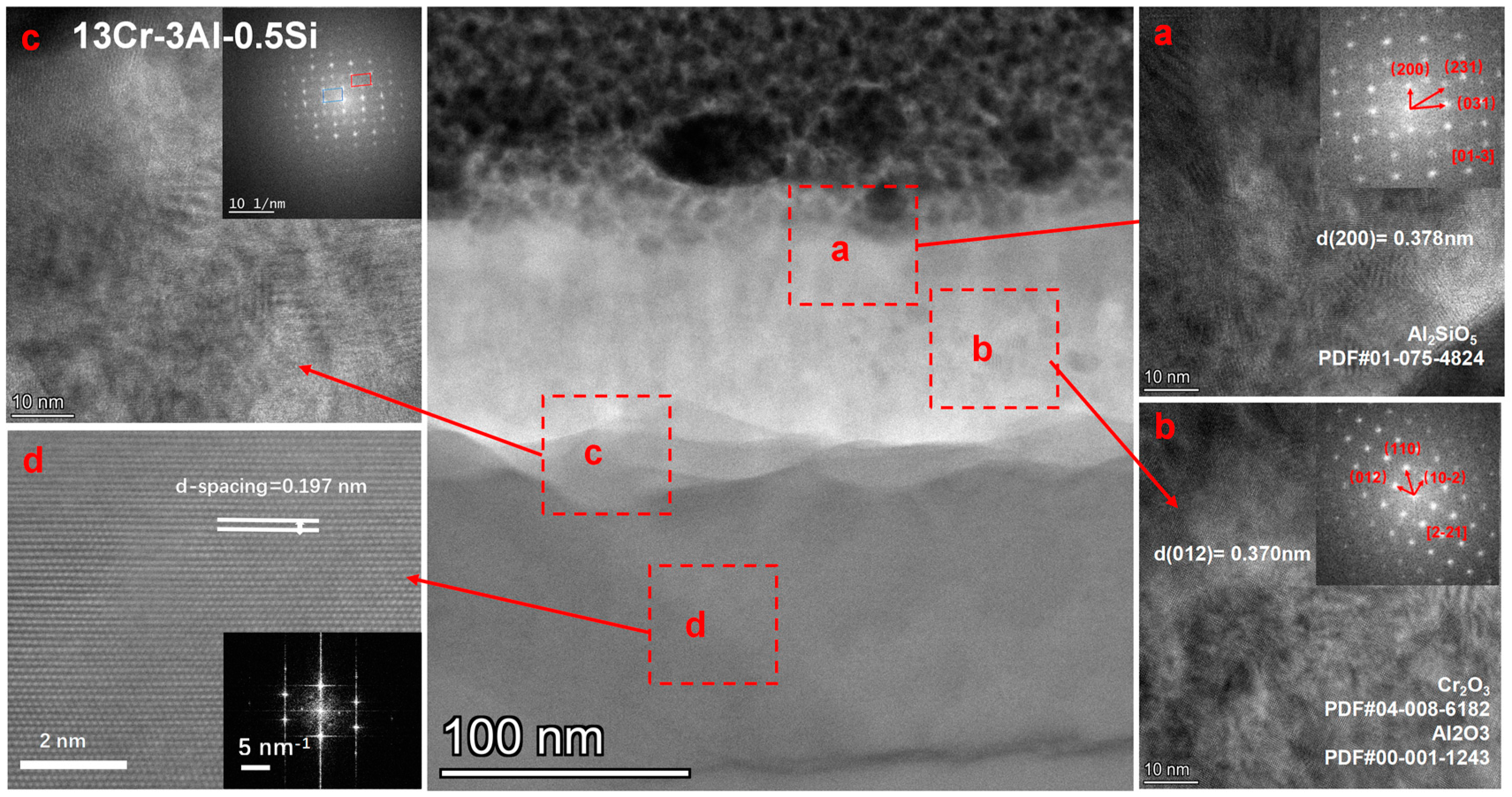
Figure 16.
High-resolution STEM analysis of the Fe-13Cr-3Al-0.5Si post 700 °C oxidation.
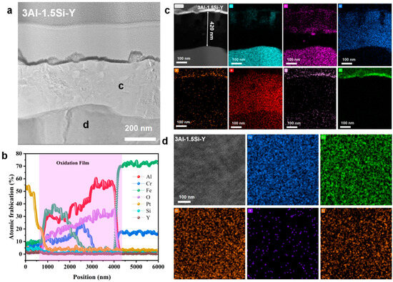
Figure 17.
Nanoscale cross-section microstructure and corresponding elemental mappings for Fe-13Cr-3Al-1.5Si-Y post 700 °C oxidation. (a) high resolution STEM image show the cross-section alteration layer; (b) elemental line scanning across the alteration layer; (c) cross section elemental mappings; (d) elemental mappings corresponding to zone d in a.
The crystalline structure of the oxide film for 13Cr-3Al-0.5Si oxidized under 700 °C can be further denoted in Figure 16. The surface is covered with a nanosized oxidation layer with a thickness of around 150 nm, featuring a polycrystalline structure as denoted in Figure 16. The matrix underneath the oxidation layer with d-spacing around 0.197 nm is consistent with the alpha-Fe crystalline phase according to the selective area diffraction pattern (SADP). The oxidation layer right above the matrix with Al-enriched can be further identified as dual-crystalline phase structures, featuring the coexistence of α-Al2O3 and Cr2O3 as denoted by the FFT pattern following the zone axis of [2,3,4,5,6,7,8,9,10,11,12,13,14,15,16,17,18,19,20,21] with d-spacing = 0.37 nm. The middle region of the oxidation film with Al-enriched demonstrates a single crystalline property, which can be indexed as α-Al2O3 with a cubic structure. The upper oxidation layer featured an Al2SiO5 crystalline phase with d-spacing = 0.378 nm, suggesting the participation of Si in the formation of the surface oxidation film. The high-resolution STEM image focused on the middle region further suggests the polycrystalline structure with an average grain size of around 50–100 nm. The nano-grains will be enlarged by thermodynamic-driven grain coarsening, as denoted in the SEM images. The top layer of the oxidation film featured with Fe-enriched can be identified as Fe2O3, with the coexistence of Fe2O3 and Al2O3. Therefore, it is reasonable to assume that the oxidation process of the FeCrAl alloys at elevated temperatures followed a stepwise sequence, with the Fe2O3 growing outward faster than Al and Cr due to the high oxygen affinity. The Cr can then be oxidized to Cr2O3 due to its oxygen affinity compared to Al.
3.4. Y Affection Based on First Principal Calculation
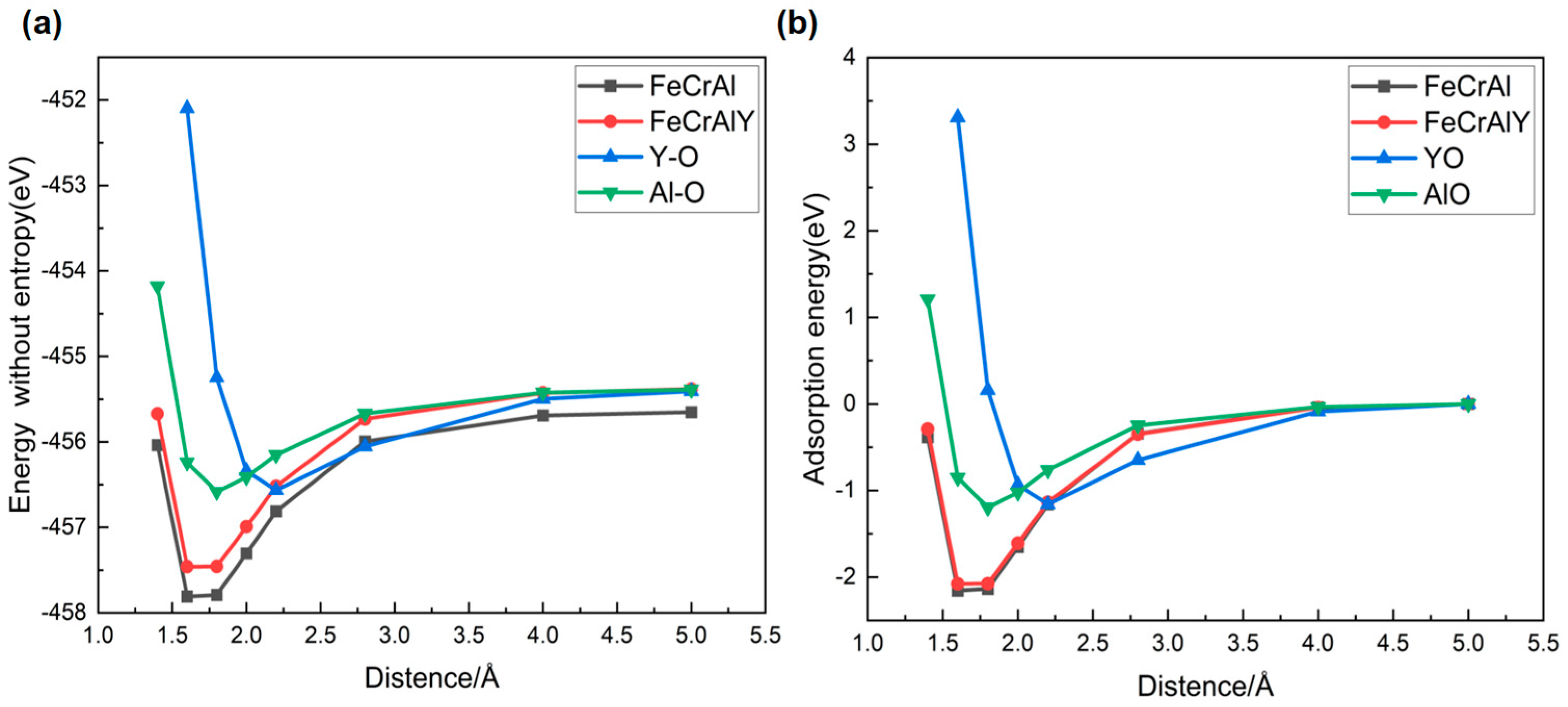
The Y affection on the surface oxidation behavior of the FeCrAl alloy was further analyzed via the first principal calculation regarding the oxygen adsorption energy and electron density (Figure 18 and Figure 19). The system energy gradually increases as the oxygen atom approaches the alloy surface, which is dominated by the physical adsorption weak van der Waals forces. The chemical interaction between the oxygen atom and the FeCrAl alloy has been enhanced by the narrowing down of the oxygen-matrix surface distance to 3.0–1.5 Å, resulting in the elevation in the atomic interaction. The bonding energy subsequently decreases by further reducing the atomic distance between oxygen and the FeCrAl alloy surface, facilitating the rapid formation of a stable metal-oxygen bond (distance below 1.5 Å). The stable metal-oxygen bond will lead to the formation of a more stable molecular structure with the system energy significantly decreased.
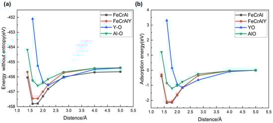
Figure 18.
comparison of system total energies (a) and adsorption energies of oxygen (b).
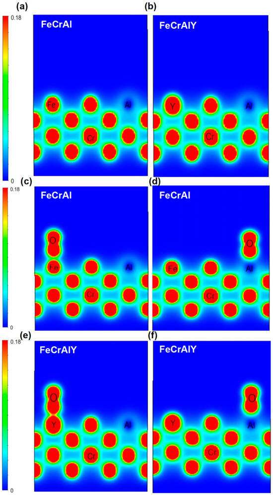
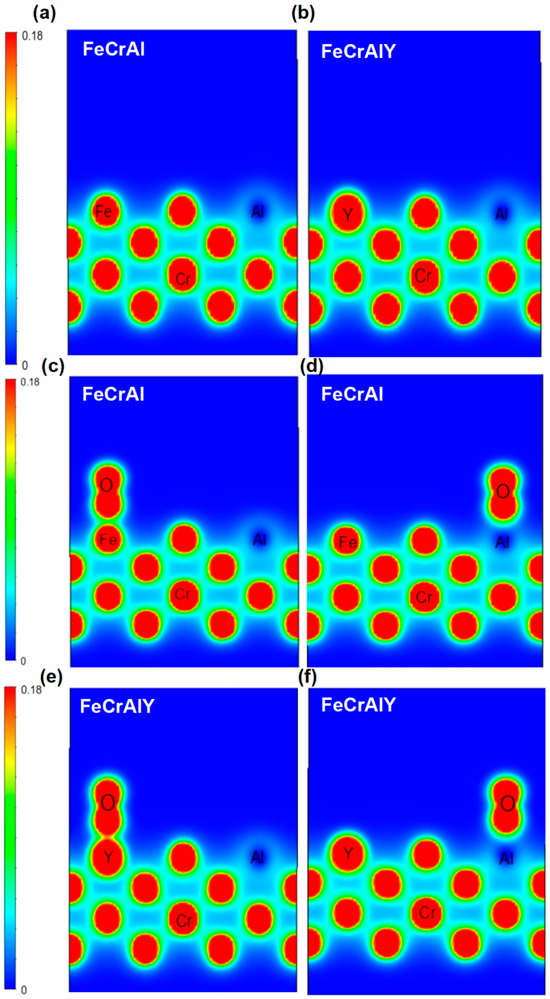
Figure 19.
Comparison of differential charge of oxygen adsorbed on different surface positions for FeCrAl and FeCrAlY alloys. (a,b) the original molecular surface; (c,d) oxygen atom stays on the Fe and Al atoms; (e,f) oxygen atom stays on the Y and Al atoms.
The electron cloud of the FeCrAlY alloy surface atoms overlaps with the electron cloud of the oxygen molecules when oxygen molecules gradually approach the surface of the alloy, forming a stronger interaction. The overlapping effect of this electron cloud will also increase the adsorption energy (Figure 19).
The charge distribution of each metal atom during the adsorption of oxygen for both FeCrAl and FeCrAlY was further calculated (Figure 19). The blue area represents the area with electron vacancy with corresponding low charge density; the red area represents the area where electrons accumulate with high electron density, while the charge density is close to zero for the green zone. It can be seen from the Figure 19 that Y has a higher charge density than Fe, Y loses electrons more easily than Fe, and the Al atom has a lower charge density at its location.
The high and uniform charge density around Fe atoms suggests that the interaction between Fe atoms is strong. The charge distribution between Cr atoms and Fe atoms is also uniform and high, suggesting the strong interaction between Cr atoms and Fe atoms is strong. The charge density around Al atoms is lower, as indicated by the blue electron cloud map. The charge distribution difference between Al atoms and Fe and Cr atoms is large, and the interaction between Al atoms and Fe and Cr atoms is weak.
Overall, the charge distribution between Fe and Cr atoms is relatively uniform, showing strong interaction, while the charge density around Al atoms is low, showing weak interaction. This may indicate that strong metallic bonds are formed between Fe and Cr atoms, while Al atoms may play a filling or regulating role in the structure.
4. Conclusions
The current work systematically studied the thermal-mechanical properties and high-temperature anti-oxidation behavior of the FeCrAl alloys with Si and Y addition. The key findings can be summarized as follows:
- The addition of Si and Y can alter the crystalline lattice by enlarging the lattice constant and further lead to a reduction in the thermal conductivity. The Y has a strong affection for the high-temperature thermal conductivity compared to the low-temperature regime. The thermal conductivity of 30 W/mK can be seen for the Fe-13Cr-6Al-Si, higher than the commercial FeCrAl alloy.
- The addition of Si will reduce the mechanical strength by making the alloy more brittle, while the mechanical strength can be enhanced by the incorporation of Y, especially in a high-temperature regime. The yield stress and tensile stress can be further enhanced through the addition of Y, which can stabilize the alloy under high temperatures with elastic deformation dominant.
- The growth of the surface oxidation film can be significantly enhanced by the addition of Y, with simultaneous suppression of the film spallation. The growth of the surface oxidation film is thermodynamically driven, as the gradual increases in the film thickness can be seen from 500 °C to 900 °C. The surface oxidation film is composed of multiple oxidation layers, featuring the coexistence of Fe, Cr, and Al oxides. The Y- and Si-enriched amorphous layer on the alloy top surface post-high-temperature oxidation suggests the outward growth of the oxidation film with Y has higher oxygen affinity.
The current study provides systematic information about the thermal-mechanical and oxidation behavior of the FeCrAl alloy. Si and Y addition has heterogeneous effects on the alloys’ properties, which can be justified by balancing the chemical composition of the alloy. The work provides a necessary insight for the future optimization of the alloy composition.
Author Contributions
Conceptualization, Y.Q.; Methodology, P.W. and Y.Q.; Software, L.Z., D.L., J.Z. and P.W.; Validation, L.Z. and D.L.; Investigation, Y.N., W.Q. and J.Z.; Data Curation, Y.N., W.Q., L.Z., D.L. and J.Z.; Writing—Original Draft Preparation, Y.N., W.Q., P.W. and K.Y.; Writing—Review and Editing, Y.N., W.Q., P.W. and K.Y.; Supervision, Y.Q. and K.Y.; Funding Acquisition, K.Y. All authors have read and agreed to the published version of the manuscript.
Funding
This work is supported by the National Key Research and Development Program of China (No. 2021YFB3500102). The Youth Fund of China University of Petroleum (East China) (No. 27RA2308009).
Data Availability Statement
The original contributions presented in this study are included in the article. Further inquiries can be directed to the corresponding authors.
Conflicts of Interest
The authors declare no conflict of interest.
References
- Yamamoto, Y.; Pint, B.A.; Terrani, K.A.; Field, K.G.; Yang, Y.; Snead, L.L. Development and property evaluation of nuclear grade wrought FeCrAl fuel cladding for light water reactors. J. Nucl. Mater. 2015, 467, 703–716. [Google Scholar] [CrossRef]
- Yamaguchi, M.; Inui, H.; Ito, K. High-temperature structural intermetallics. Acta Mater. 2000, 48, 307–322. [Google Scholar] [CrossRef]
- Sweet, R.; George, N.; Maldonado, G.; Terrani, K.; Wirth, B. Fuel performance simulation of iron-chrome-aluminum (FeCrAl) cladding during steady-state LWR operation. Nucl. Eng. Des. 2018, 328, 10–26. [Google Scholar] [CrossRef]
- Raiman, S.S.; Field, K.G.; Rebak, R.B.; Yamamoto, Y.; Terrani, K.A. Hydrothermal corrosion of 2nd generation FeCrAl alloys for accident tolerant fuel cladding. J. Nucl. Mater. 2020, 536, 152221. [Google Scholar] [CrossRef]
- Unocic, K.A.; Yamamoto, Y.; Pint, B.A. Effect of Al and Cr content on air and steam oxidation of FeCrAl alloys and commercial APMT alloy. Oxid. Met. 2017, 87, 431–441. [Google Scholar] [CrossRef]
- Young, S.-W.; Sato, M.; Yamamitsu, K.; Shimada, Y.; Zhang, Y.; Miyamoto, G.; Furuhara, T. Effect of alloying elements on the high-temperature tempering of Fe-0.3 N martensite. Acta Mater. 2021, 206, 116612. [Google Scholar] [CrossRef]
- Park, D.J.; Kim, H.G.; Park, J.Y.; Jung, Y.I.; Park, J.H.; Koo, Y.H. A study of the oxidation of FeCrAl alloy in pressurized water and high-temperature steam environment. Corros. Sci. 2015, 94, 459–465. [Google Scholar] [CrossRef]
- Pan, D.; Zhang, R.; Wang, H.; Lu, C.; Liu, Y. Formation and stability of oxide layer in FeCrAl fuel cladding material under high-temperature steam. J. Alloys Compd. 2016, 684, 549–555. [Google Scholar] [CrossRef]
- Wang, P.; Qi, W.; Yang, K.; Qiao, Y.; Wang, X.; Zheng, T.; Bai, C.; Liu, Z.; Zhang, X. Systematic investigation of the oxidation behavior of Fe-Cr-Al cladding alloys in high-temperature steam. Corros. Sci. 2022, 207, 110595. [Google Scholar] [CrossRef]
- Qi, W.; Yang, K.; Wang, P.; Du, S.; Bai, C.; Wang, X.; Qiao, Y.; Zheng, T.; Zhang, L.; Zhang, X. High-temperature steam oxidation behavior of an FeCrAl alloy with controlled addition of Mo. J. Mater. Sci. 2022, 57, 20909–20927. [Google Scholar] [CrossRef]
- Weisenburger, A.; Jianu, A.; Doyle, S.; Bruns, M.; Fetzer, R.; Heinzel, A.; DelGiacco, M.; An, W.; Müller, G. Oxide scales formed on Fe–Cr–Al-based model alloys exposed to oxygen containing molten lead. J. Nucl. Mater. 2013, 437, 282–292. [Google Scholar] [CrossRef]
- Qiao, Y.; Wang, P.; Qi, W.; Du, S.; Liu, Z.; Meng, F.; Zhang, X.; Wang, K.; Li, Q.; Yao, Z. Mechanism of Al on FeCrAl steam oxidation behavior and molecular dynamics simulations. J. Alloys Compd. 2020, 828, 154310. [Google Scholar] [CrossRef]
- Qi, W.; Qiao, Y.; Ru, W.; Wang, X.; Zhang, X.; Zheng, T.; Du, S.; Wang, P.; Yang, K. High-temperature steam oxidation and surface microstructure evolution of Fe13Cr6Al (1–4) Mo0.15Y alloys. Metals 2024, 14, 1229. [Google Scholar] [CrossRef]
- Heinonen, M.; Kokko, K.; Punkkinen, M.P.J.; Nurmi, E.; Kollár, J.; Vitos, L. Initial oxidation of Fe–Al and Fe–Cr–Al alloys: Cr as an alumina booster. Oxid. Met. 2011, 76, 331–346. [Google Scholar] [CrossRef]
- Gunduz, K.O.; Visibile, A.; Sattari, M.; Fedorova, I.; Saleem, S.; Stiller, K.; Halvarsson, M.; Froitzheim, J. The effect of additive manufacturing on the initial High temperature oxidation properties of RE-containing FeCrAl alloys. Corros. Sci. 2021, 188, 109553. [Google Scholar] [CrossRef]
- Qiao, C.; Zhang, H.; Wu, F.; Qiao, S.; Dai, C.; Zhang, X.; Sun, M.; Liao, B.-K.; Shen, Y.; Hao, L. Rare earth addition powered corrosion resistance of the surface oxide film on GCr15 bearing steel substrate. Corros. Sci. 2024, 240, 112490. [Google Scholar] [CrossRef]
- Kim, S.; Lee, C.-H.; Kim, T.; Jang, J.H.; Moon, J.; Falaakh, D.F.; Kim, J.H.; Bahn, C.B. Effects of yttrium on the oxidation behavior of Fe13Cr6AlY alloys under 1200° C steam. J. Alloys Compd. 2023, 960, 170642. [Google Scholar] [CrossRef]
- Riffard, F.; Buscail, H.; Caudron, E.; Cueff, R.; Issartel, C.; Perrier, S. In-situ characterization of the oxide scale formed on yttrium-coated 304 stainless steel at 1000° C. Mater. Charact. 2002, 49, 55–65. [Google Scholar] [CrossRef]
- Ramanarayanan, T.; Raghavan, M.; Petkovic-Luton, R. Metallic yttrium additions to high temperature alloys: Influence on Al2O3 scale properties. Oxid. Met. 1984, 22, 83–100. [Google Scholar] [CrossRef]
- Banoth, S.; Palleda, T.N.; Saito, T.; Murakami, H.; Kakehi, K. Effects of yttrium and silicon contents in Hastelloy-X built by selective laser melting process. J. Alloys Compd. 2022, 896, 163050. [Google Scholar] [CrossRef]
- Ejenstam, J.; Thuvander, M.; Olsson, P.; Rave, F.; Szakalos, P. Microstructural stability of Fe–Cr–Al alloys at 450–550 C. J. Nucl. Mater. 2015, 457, 291–297. [Google Scholar] [CrossRef]
- Tuo, J.-y.; Zhang, R.-q.; Cai, Z.-b.; Du, P.-n.; Yu, Y.-q. Effect of annealing temperature on the microstructure and mechanical properties of laves phase reinforced FeCrAl alloy thin-walled tubes. J. Nucl. Mater. 2022, 561, 153561. [Google Scholar] [CrossRef]
- Mortazavi, A.; Esmaily, M.; Geers, C.; Birbilis, N.; Svensson, J.-E.; Halvarsson, M.; Chandrasekaran, D.; Johansson, L. Exploring failure modes of alumina scales on FeCrAl and FeNiCrAl alloys in a nitriding environment. Acta Mater. 2020, 201, 131–146. [Google Scholar] [CrossRef]
- Aragón, P.; Feria, F.; Herranz, L.E. Modelling FeCrAl cladding thermo-mechanical performance. Part I: Steady-state conditions. Prog. Nucl. Energy 2022, 153, 104417. [Google Scholar] [CrossRef]
- Lunn, K.F.; Apelian, D. Thermal and Electrical Conductivity of Aluminum Alloys: Fundamentals, structure-property relationships, and pathways to enhance conductivity. Mater. Sci. Eng. A 2024, 924, 147766. [Google Scholar]
- Chen, T.; Li, G.; Wang, H.; An, X.; Huang, X. Effect of Si content on the mechanical behavior and microstructure of a 9Cr ferritic/martensitic steel. J. Mater. Res. Technol. 2024, 29, 1542–1556. [Google Scholar] [CrossRef]
- Huang, X.; Wang, H.; Qiu, S.; Zhang, Y.; He, K.; Wu, B. Cold-rolling & annealing process for nuclear grade wrought FeCrAl cladding alloy to enhance the strength and ductility. J. Mater. Process. Technol. 2020, 277, 116434. [Google Scholar]
- Deng, Z.; Liu, J.; Yan, B.; He, Y. Monotonous deformation behavior of ferritic FeCrAl alloy in the dynamic strain aging regime. J. Alloys Compd. 2018, 749, 664–671. [Google Scholar] [CrossRef]
- Xu, Z.; Lu, Z.; Zhang, J.; Li, D.; Liu, J.; Lin, C. The friction and wear behaviours of Inconel 718 superalloys at elevated temperature. Front. Mater. 2021, 8, 794701. [Google Scholar] [CrossRef]
- Döleker, K.M.; Erdogan, A.; Yener, T.; Karaoglanlı, A.C.; Uzun, O.; Gök, M.S.; Zeytin, S. Enhancing the wear and oxidation behaviors of the Inconel 718 by low temperature aluminizing. Surf. Coat. Technol. 2021, 412, 127069. [Google Scholar] [CrossRef]
- Aydogan, E.; Weaver, J.S.; Maloy, S.A.; El-Atwani, O.; Wang, Y.; Mara, N.A. Microstructure and mechanical properties of FeCrAl alloys under heavy ion irradiations. J. Nucl. Mater. 2018, 503, 250–262. [Google Scholar] [CrossRef]


Disclaimer/Publisher’s Note: The statements, opinions and data contained in all publications are solely those of the individual author(s) and contributor(s) and not of MDPI and/or the editor(s). MDPI and/or the editor(s) disclaim responsibility for any injury to people or property resulting from any ideas, methods, instructions or products referred to in the content. |
© 2025 by the authors. Licensee MDPI, Basel, Switzerland. This article is an open access article distributed under the terms and conditions of the Creative Commons Attribution (CC BY) license (https://creativecommons.org/licenses/by/4.0/).