3.2. Nozzle Clearance Distance
The distance between the nozzle tip and the water surface is important to wire formation. The optimum distance was found to be 2–4 mm. In the multi-stream configuration [
35], it was important to use optically flat glass discs for drilling of orifices located in the nozzle base with the line of the orifice perpendicular to the direction of water flow, in order to maintain the same distance to the water surface by all of the melt streams. A slight curvature tended to develop on the flat disc as a result of fusion to the crucible base, but this generally had no perceptible effect on the ability to cast geometrically acceptable glassy wires. It was practically difficult to bring the nozzle tip closer than 2 mm to the surface of the water because of the risk of contact with the cooling water which results in cracking due to thermal shock. On the other hand, distances of greater than 4 mm usually led to stream break up and the formation of powder or short pieces of fibres.
It is important to consider the contribution of nozzle clearance distance to the stability of melt stream. Due to the effect of surface tension and viscosity, a liquid jet will tend to break into droplets. The theoretical and experimental studies of break up length of a free jet has attracted lots of attention [
39,
40] and the critical parameter to establish stability is conventionally expressed as the length to diameter ratio (
L/
d). The critical (
L/
d) ratio for a coherent isothermal liquid jet depends on the streaming conditions characterised by dimensionless numbers and can be expressed by the modified Weber equation [
12,
39]:
where
We is the Weber number given by
and Re is the Reynolds number given by
, σ, ρ, and η, are respectively the surface tension, density and dynamic viscosity of the melt.
The log term
is an experimental parameter relating to the perturbation at the emergence of the jet from the nozzle and is approximately 12 for a wide variety of liquids and streaming conditions [
38]. Typical wire casting conditions, for which
vm ≈ 10 ms
−1, and taking the values of melt physical properties given in [
41], imply
We ≈ 10 and Re ≈ 10
4, thus giving
L/
d ratio of approximately 40. A critical
L/
d of 40 is in accord with experimental observation and model prediction given in ref [
40] for Re = 10
3–10
4. For a 100 μm diameter melt jet, this corresponds to a jet break-up length of 4 mm. This is ostensibly in fairly good accord with the present experimentally observed critical nozzle distance of less than 4 mm for casting continuous metallic glass wire. However, it has been shown that the break-up length for an oxide-forming melt is at least one order of magnitude greater than that predicted from Equation (2).
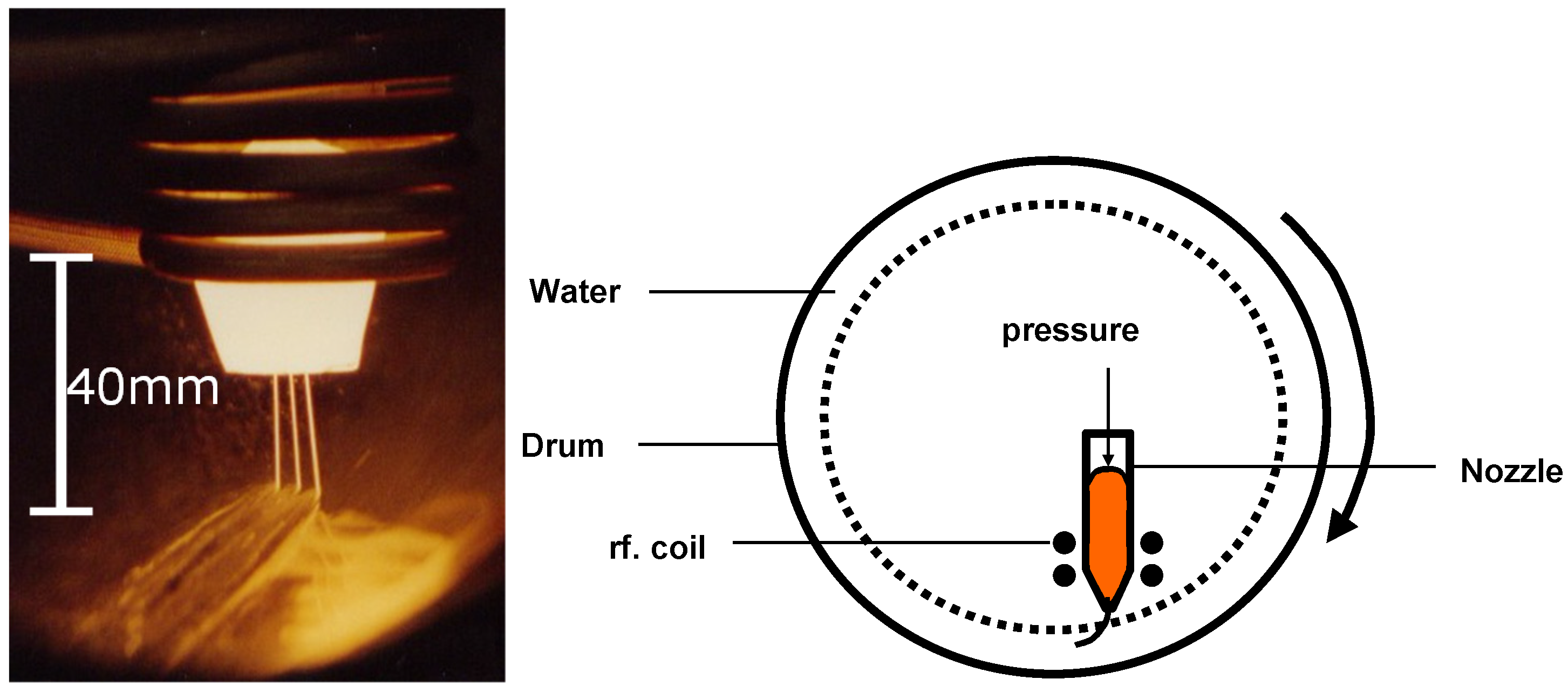
Figure 2 shows a photograph of melt streams maintained at the typical wire casting condition, and observed unbroken for lengths well over 20 mm. It is seen that a coherent jet could still be maintained under casting conditions for lengths well above the critical value predicted from Equation (2). Nevertheless, the inability to produce continuous amorphous wire with clearance distances over 4 mm was an indication of instability of the flow setting-in irrespective of oxide protection. The fact that, even beyond this predicted limiting length of 4 mm, short brittle fibres could still be produced suggests that nozzle-water clearance distance in itself is not strictly a limiting factor on the stability of the stream up to the point of entry of the jet into the quenching water. However, the distance needs to be kept to less than 4 mm, partly to minimise velocity rise due to gravitational acceleration and also to minimise air cooling of the melt stream and, thus, maximising the quenching rate required for the vitrification of the melt. For longer nozzle-water clearance, the drop in temperature imposed from air-cooling would reduce the temperature differential between the melt stream and the quenching medium and may, thus, result in a cooling rate below the critical cooling rate for glassy wire production.
Figure 2.
(a) Unbroken melt jet streams maintained for over 20 mm under streaming conditions. (b) Schematic diagram of the wire casting.
3.3. Nozzle Diameter and Jet Contraction
For most compositions investigated, continuous wire production was limited to diameters between 80 and 150 μm. Outside these ranges, powder or short pieces of fibres were produced, indicating an unstable melt stream during casting attempts. The lower limit of 80 μm was imposed by the shorter distance at which instability sets in and also by the difficulty of initiating flow of the viscous melt through the nozzle. In order to increase the L/d ratio (as predicted in Equation (2)), it would have been necessary to increase cast pressure which again was limited by the ability of the crucible material to withstand higher pressures at the casting temperatures. Additionally, at small diameters, blockage of nozzles was a problem that constantly disturbed and caused instability in the melt stream.
At larger nozzle diameters (d > 150 μm), the cooling rate becomes a problem. Although it was easier to maintain a stable stream (as predicted by Equation (2)), from heat transfer considerations, the average cooling rate of the melt was reduced for large diameters. This had implications for the solidification rate. The success of forming continuous wire is ultimately dependent on rapid solidification of the molten jet stream. The longer the solidification times, experienced with larger diameters, the greater the effect of forces related to momentum change as the melt stream changed course in the stream on confluence. Incomplete solidification would therefore cause the break-up of the stream leading to powders or short fibres. Additionally, the reduced cooling rates may be below the critical rate for glass formation in that particular composition being cast, thus resulting in a partially or fully crystalline brittle wire.
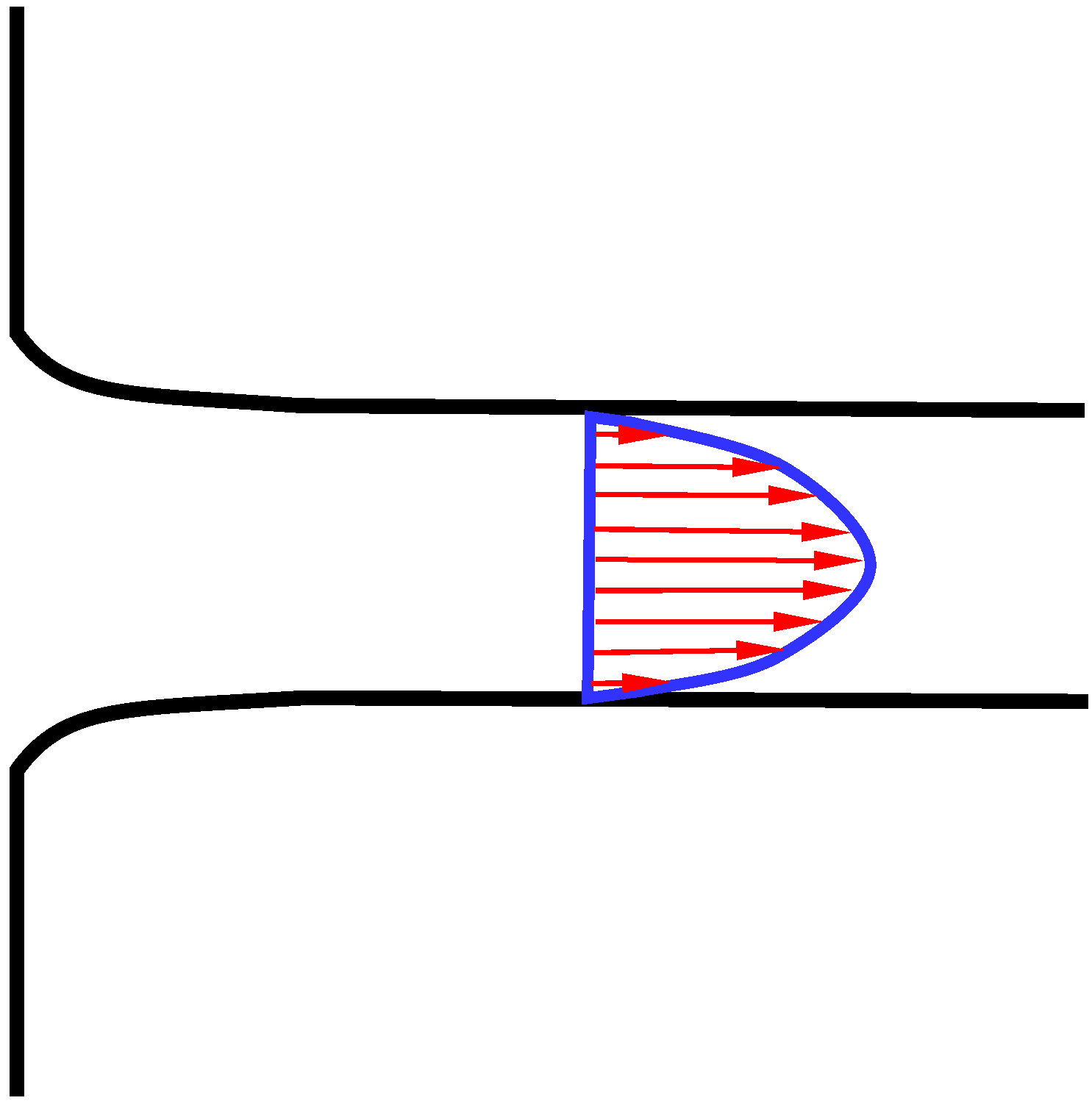
Generally, it was observed that the wire diameter is about 10% smaller than the nozzle diameter, thus signifying a jet contraction in flight during casting. Such contraction can be explained if we consider the relaxation of the velocity profile that exists across the jet stream. A simplified approach to predicting such contraction from velocity relaxation would be to assume a fully developed laminar flow across the nozzle at the point of exit. The velocity profile as depicted in
Figure 3 can then be expressed as that given for a laminar non-compressible fluid over a flow length
L as [
37]:
where
R is the radius of the nozzle and
r represents the radial distance from the centreline.
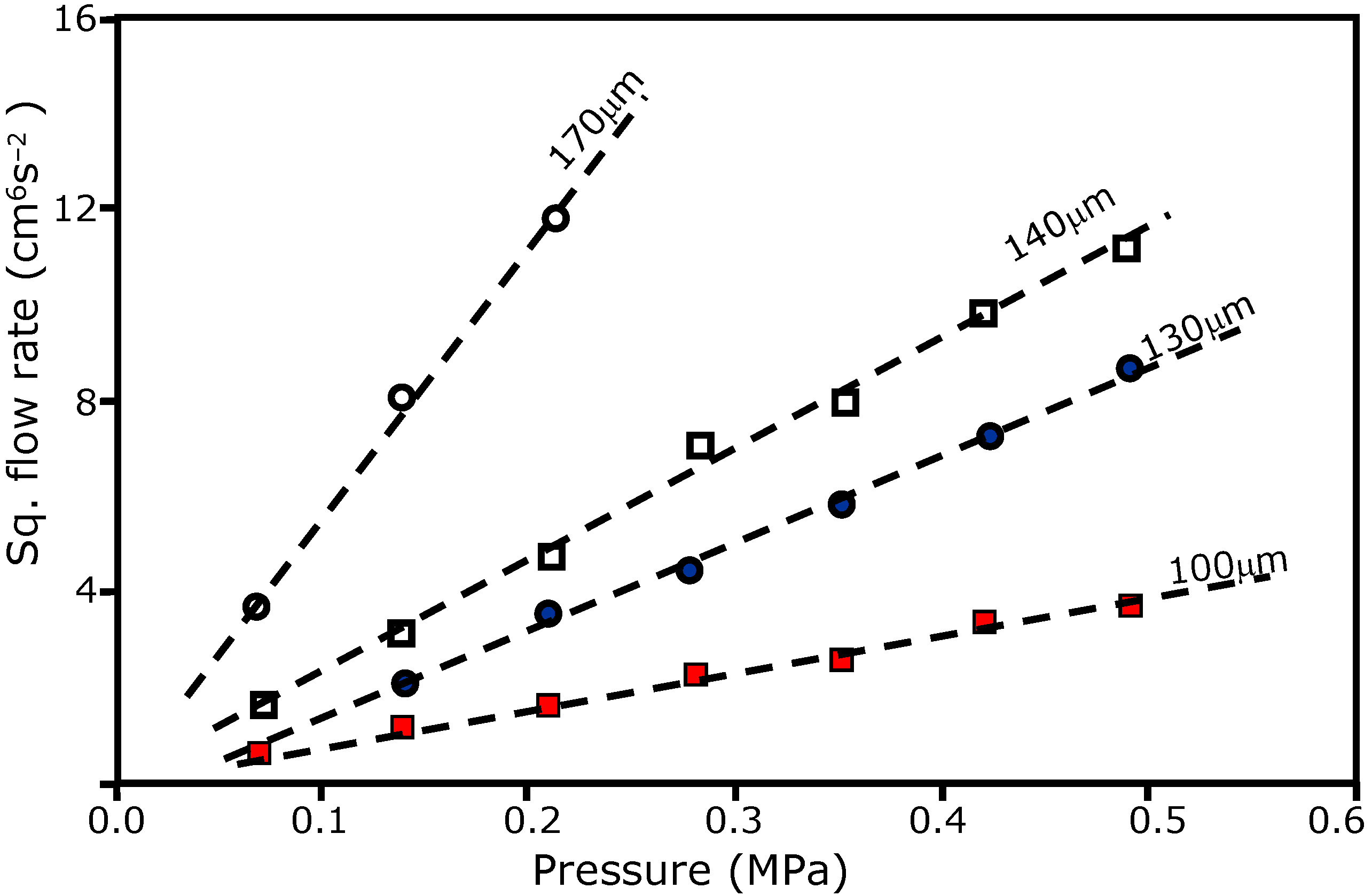
It could be shown that the mass flow rate (
ṁ) is [
37]:
On emergence from the nozzle, the melt stream condition is equivalent to that in which the fixed boundary of the nozzle is suddenly removed. The streamlines near the boundary, having initially zero velocity, will accelerate. The most simplified scenario is to assume acceleration to the centre line velocity which is the maximum of the velocity profile equation (Equation (3)) and is given by [
37]:
The mass flow rate
ṁ' of a contracted free jet with reduced radius
R' is given by:
For mass conservation, we expect that flow rate remains the same before and after jet contraction and this implies that:
This analysis predicts a jet contraction of
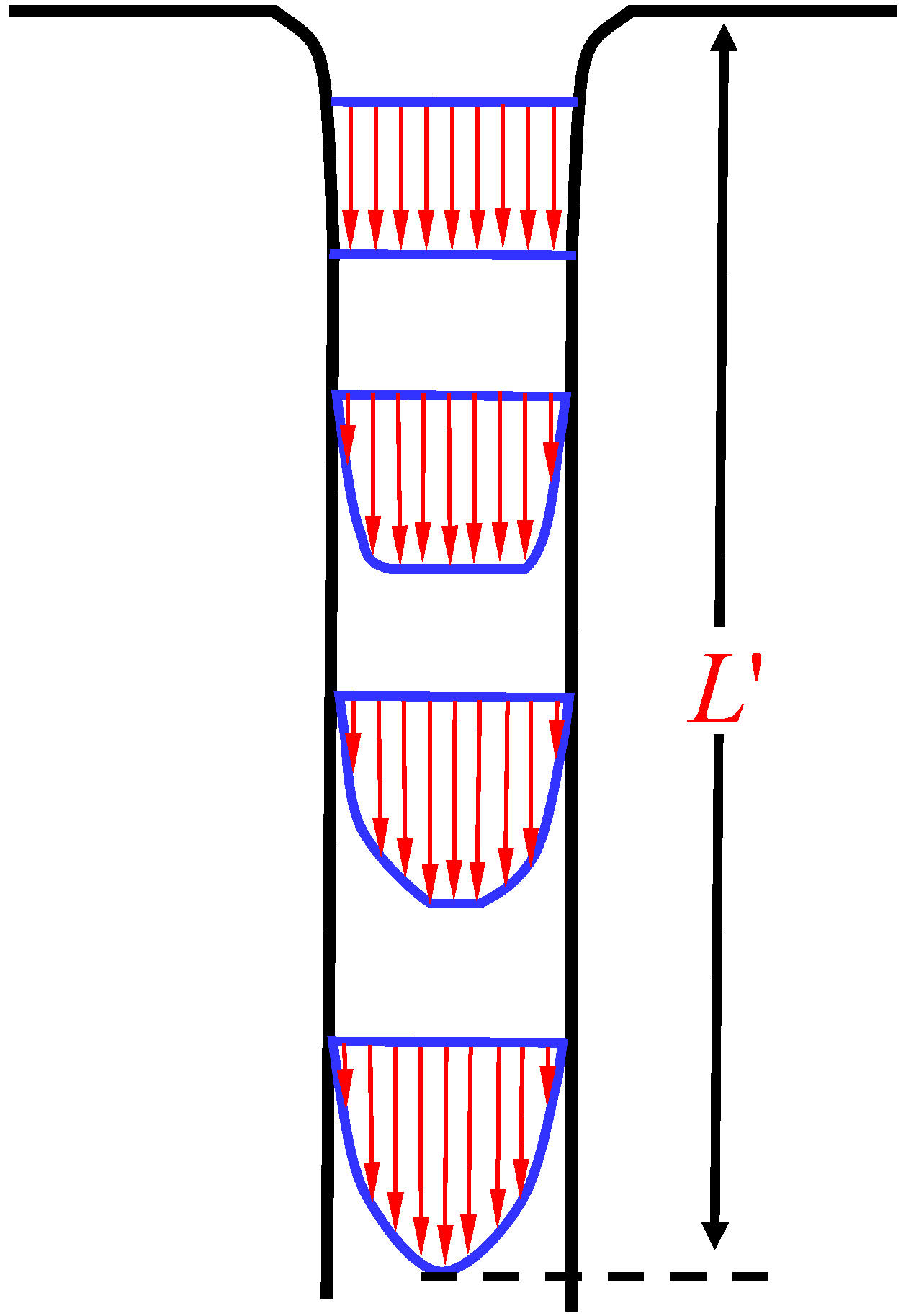
(~30%) which clearly is an overestimation when compared with the experimental results of about 10%. A drawback to the theoretical prediction of jet contraction in short bore orifices as in nozzles for wire casting can be the incomplete description of hydrodynamic flow within the jet. A schematic model of flow development is shown in
Figure 4. A semi-empirical fluid mechanics approach suggests [
37] that, to fully establish (99%) laminar flow, an
L/
d ratio of 116 is required. This translates to bore lengths of greater than 12 mm for a typical nozzle orifice diameter of 100 μm, normally used for wire casting. In practice, nozzles are converging and with lengths of the order of a few millimeters. The assumption of a fully developed laminar flow in this analysis, therefore, cannot truly represent the streaming conditions of the nozzle in the wire casting process. Nevertheless, the analysis here qualitatively explains the observed contraction from a possible relaxation of a streamline velocity profile across the jet in free flight.
Figure 3.
Schematic representation of velocity profile in a fully developed laminar flow.
Figure 4.
Schematic representation of flow development showing critical length for fully developed laminar flow.
3.4. Melt Superheat
The optimum superheat for continuous wire formation was found [
35] to be 100–150 K. Lower superheats cause fluidity problems resulting in premature nozzle blockage that prevented the formation of a coherent jet. Excessive superheat could lead to nozzle distortion that affects the dynamics of fluid flow through the nozzle. Moreover, large superheats imply a longer solidification time which would be detrimental to maintaining a continuous flow of the melt stream before initial solidification occurs. It has been shown [
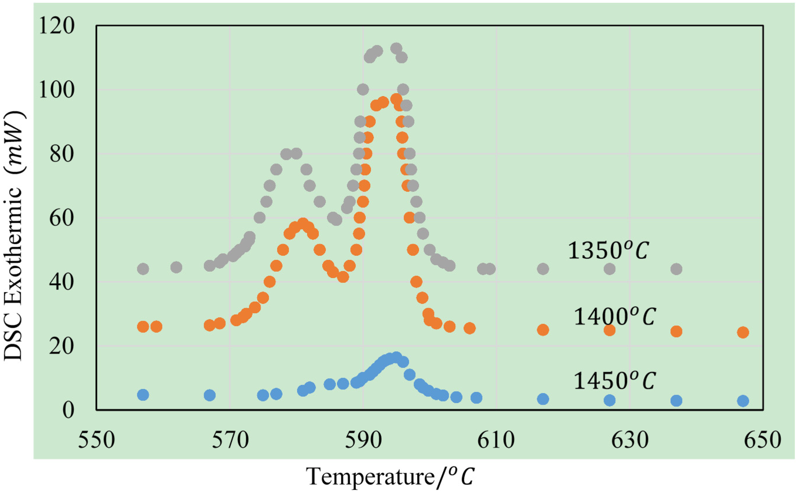
35] that large superheat resulted in partially crystalline wire as indicated by the sharp crystalline peaks of XRD pattern for wire samples with superheat greater than 100 K. For an alloy composition of Fe
77.5Si
7.5B
15, the role of excessive superheat on melt in the cast wire is shown on the DSC crystallisation thermograms in
Figure 5. Here, it is seen that crystallisation peaks for metallic glass cast at high melt temperature (1450 °C) are much lower smaller compared to those cast at lower temperatures (
i.e., with less superheat). The indication then is that for excessive superheat, complete vitrification is not achieved. The longer cooling intervals associated with a large superheat resulted in incomplete vitrification, and it is particularly more evident for larger diameters, for which the margin for glass formation is narrower for most compositions.
Ordinarily, for heat transfer considerations, we would expect a large superheat to translate to a higher average cooling rate of the melt if complete Newtonian cooling was responsible for the heat transfer. However, limitations exist in heat transfer coefficients when a solid is being cooled in a liquid medium from a temperature well above the boiling point of the cooling liquid. In this case, expected boiling (at 100 °C) would mean the wire would be encased in a steam jacket initially and the increased temperature potential from additional superheat would not lead to increased average cooling rate as would be expected from a fully Newtonian cooling; rather, the longer solidification time would prove the kinetic lag for diffusive atomic rearrangement into crystalline structure. Although superheat is not critical to melt jet stability, its role in reducing glass-forming can lead to the formation of partially crystalline and subsequently brittle wire that tends to break into short fibres or fragment into powders.
Figure 5.
Effect excessive superheat on the degree of vitrification on as-cast wire.
3.5. Effect of Water and Jet Velocity
Velocity mismatch between melt stream and cooling stream has long been recognised [
5] as one of the possible contributors to break up forces that cause instability in the melt stream. In the water bath process, the ratio of the velocities of the melt stream and the water bath (
vm/
vw) has been found to be a critical factor for continuous wire formation. Depending on alloy composition, we have found [
35] that the critical values of
vm/
vw range from 1.1–1.21, still within the wider range of 1–2 proposed originally by Masumoto
et al. [
6]. However, these studies were directed at casting both crystalline and amorphous alloys wires. Some effects of the magnitude of
vm/
vw on the morphology of wire for the glass-forming alloy FeCrSiB are shown in
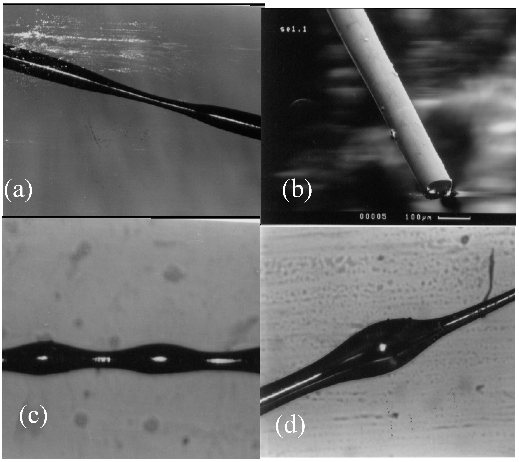
Figure 6. These illustrate the effects of the various deformation forces on the liquid jet prior to solidifying.
Figure 6.
Some of the effects of vm/vw ratios on wire morphology (optical for (a) (c) and (d); and SEM for (b)) wire morphology (a) vm/vw = 1.3 (b) vm/vw = 1.1 (c) vm/vw = 0.9 (d) vm/vw = 1.5.
The significance of the velocity ratio
vm/
vw for this casting process lies in the forces imposed on the melt jet as it changes course from an initial stream velocity
vm to be in confluence with the quenching water bath having a velocity
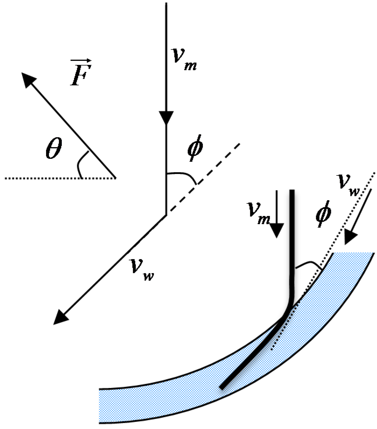
vw. Previous studies suggest matching the two stream velocities would maintain continuity in the transition of the molten stream to solid filament. However, the change in direction of jet on entry into the water imposes a substantial force on it. The velocity change of the jet and the force exerted on it on entry into the water bath are depicted in
Figure 7. Resolving the velocities, and applying Newton’s second law to the jet trajectory, the force
imposed from the momentum change is given in vector form by the equation:
where
i and
j are unit vectors respectively along the horizontal and vertical axes.
The direction and magnitude of
is most critical to the stability of the jet. The direction depicted by angle θ in
Figure 7, is given by:
We can consider two limiting conditions for the stability of the jet; one for which magnitude of the force
is minimum but completely shearing and the other where the direction indicates an equal distribution between the shear and tensile or compression; i.e. we choose θ = 45°. In the case of the former,
. For the limiting condition of θ = 45°,
. In practice, wire casting successfully relies on minimising magnitude of the interaction force and optimising its distribution into shearing and direct. It is therefore expected that an optimum casting condition would be between these two limiting conditions as:
It is clear that stability of jet due to momentum change is dependent on both the velocity ratio vm/vw and the jet entrant angle . Since angle is normally kept constant, (though in our experiments it was kept at 30°) we can redefine the range for which the critical vm/vw value must lie in the range: 0.87 < vm/vw < 1.37. This is consistent with experimental observations for which critical vm/vw for FeCrSiB melt was found to be 1.1–1.21. Outside the optimal range, the direction θ of the imposed force would upset the force component allowing either of the shearing or compressive forces to predominate leading respectively to powder or deformed wire. The criticality of the ratio vm/vw is confined to a narrow range so that it gives a minimum shear component of force imposed by the momentum change.
Figure 7.
Velocity change and force exerted at the confluence of melt and water streams.
3.6. Effect of Alloy Composition
It was found [
35] that for the compositional series Fe
85−xSi
xB
15, a minimum silicon content of 5% was required for continuous wire formation even with very strict process control. Replacement of Fe with Cr was also found to increase the wire forming ability, within a broader window of values of
vm/
vw for continuous wire formation.
The influence of oxide formers on wire forming ability has long been recognized [
10]. The natural tendency of a melt stream to disintegrate into droplet decreases with the presence of a coherent oxide skin. It is consistent with the earlier analysis in that we expect a larger than predicted
L/
d ratio and thus a longer break-up length of free jet for a strong oxide-forming melts. The presence of an oxide skin on a melt would lead to greater shear resistance of the free jet. This would stabilize the jet against breakage notably when the momentum changed as the melt stream altered course as it travelled through confluence and finally achieved the speed of the quenching water.
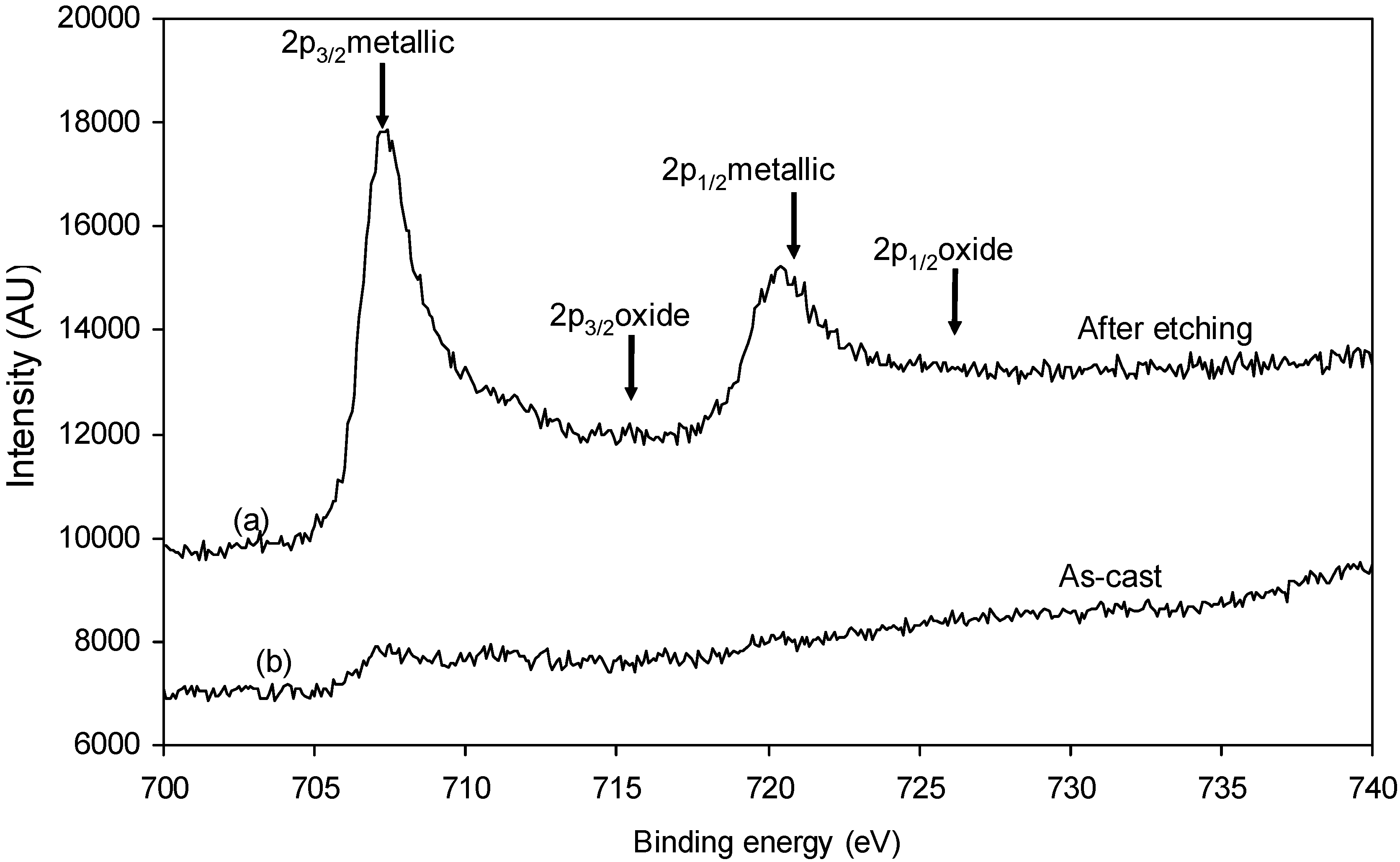
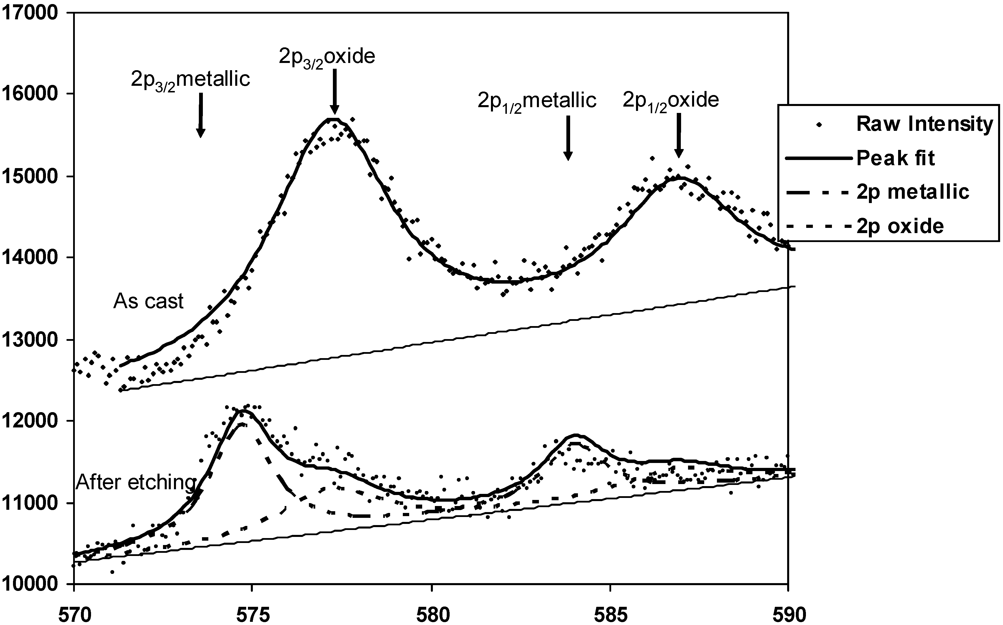
Figure 8.
XPS Fe 2p in as-cast and after Ar+ sputtering.
Figure 9.
XPS Cr 2p peak fitting for standard Cr and Cr2O3 for as-cast wire and after ion sputtering.
The role of Si and Cr in forming oxides was confirmed through surface analysis of cast wires of composition Fe
69.5Cr
8Si
7.5B
15 with X-ray photo electron spectroscopy (XPS).
Figure 8 shows the Fe 2p characteristic spectrum for as-cast and Ar
+ sputtered wire samples. It is clear that the surface has very weak Fe signal on the as-cast sample but the Fe 2p signal becomes more pronounced after prolonged etching that removed the surface oxide. The characteristic Fe 2p
3/2 and 2p
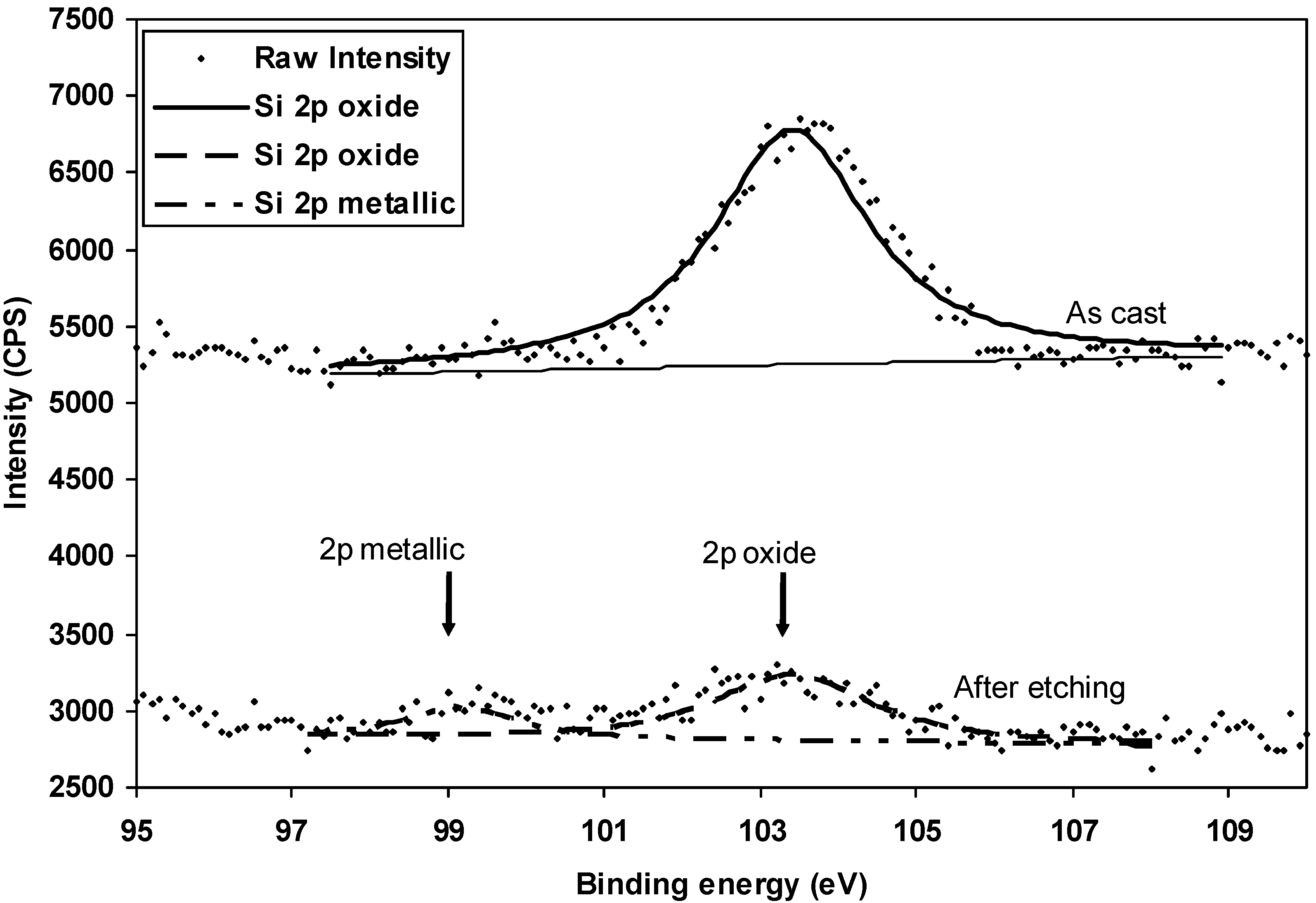
1/2 are clearly indicative of metallic, thus confirming that the surface composition is essentially different from the bulk. Similar Cr-2p and Si-2p lines are respectively shown in
Figure 9 and
Figure 10. It is shown in these figures that both the Cr 2p and Si 2p XPS characteristic peaks for the as-cast wire fit more closely with standard oxide spectra. These characteristic peaks move closer to metallic after Ar
+ sputtering. The comparison of the XPS spectra (
Figure 8,
Figure 9 and
Figure 10) for as-cast and sputtered samples confirms the compositional difference of the surface and the core of the wire samples. The present XPS evidence suggests that the surface consisted essentially Si and Cr oxides. Semi-quantitative analyses of these peaks based on integrated areas and applying sensitivity factors, suggest that Cr/Fe and Si/Fe atomic ratios were respectively 1.2 and 3.9. These values are much higher than the nominal Cr/Fe and Si/Fe atomic ratios of ≈0.1 that are expected from the nominal composition of the bulk alloy.
Figure 10.
XPS Si 2p peak fitting for standard SiO2 for as-cast wire and after ion sputtering.
It is somewhat surprising that the Fe 2p for the un-sputtered samples indicate almost no presence of Fe. The result of the Fe 2p due to light etching confirmed this is only limited to the surface and must be related to the oxide-forming tendencies of the constituents Si and Cr elements. The relative influence of elements on oxide formation according to thermodynamic drive [
42] derived from free energies for oxide formation would be of the order Si > Cr > Fe and this is consistent with the present XPS observations. Since both Si and Cr at high temperatures have much higher negative free energies for oxide formation, even their presence in relatively small concentration (7–8 at%) would give a thermodynamic and kinetic preference for their oxide formation over the main (Fe) alloy constituent. This XPS evidence confirms the important roles of Si and Cr in forming a coherent oxide skin which stabilizes the free flight of the melt jet and, thus, allows more flexibility with the process variables in forming wires.


