Article

Influence of Milling on the Fatigue Lifetime of a Ti6Al4V Titanium Alloy

1
Institut Clement Ader, Universite Toulouse 3-Paul Sabatier, 3 rue Caroline Aigle, F-31400 Toulouse, France
2
Institut Superieur de l'Aeronautique et de l'Espace, 10 avenue Edouard-Belin, 31055 Toulouse Cedex 4, France
3
Intitut de Recherche Technologique, 4 rue Augustin Fresnel, 57070 Metz, France
*
Author to whom correspondence should be addressed.
Metals 2015, 5(3), 1148-1162; https://doi.org/10.3390/met5031148
Submission received: 11 February 2015 / Revised: 8 June 2015 / Accepted: 23 June 2015 / Published: 30 June 2015
(This article belongs to the Special Issue Titanium Alloys)

Abstract

:
The present article focuses on the influence of machining on the fatigue life of a titanium alloy: Ti6Al4V. An experimental design was adopted in order to highlight the effects of machining parameters on surface integrity while generating very different surfaces with a view to subsequent fatigue testing (four point bending tests). Firstly, the impact of machining parameters on surface integrity was demonstrated. Then, the influence of surface integrity on fatigue lifetime was observed: no influence of the geometric and metallurgical parameters was observed. However, the mechanical parameter (e.g., residual stress) seemed to have a preponderant influence. To conclude, a machining plan of procedure was proposed to significantly improve the fatigue lifetime as compared with a reference industrial plan of procedure.

1. Introduction

Milling is a major shaping process used to manufacture structural metal parts for aeronautical applications. Many of these parts are made of titanium alloy, a metal that is light in weight, remains mechanically strong at high temperatures and has good corrosion resistance. However, titanium alloys are known to be difficult to machine precisely due to their physical and mechanical properties [1]. Such parts have to be of high quality and especially resistant to fatigue. Indeed, fatigue is one of the main causes of damage to aviation structures. The phenomenon results from cyclical variations in mechanical stresses in flight and is characterised by three phases: initiation of cracks, their propagation and then final failure. In Novovic et al. [2], examination of the fracture morphology shows that in most cases crack initiation starts on the surface and persistence of the crack then represents 90% of the part’s lifetime. The surface integrity of part can be significantly modified by the manufacturing process, especially machining, and can generally be defined by the geometric (roughness), mechanical (residual stresses) and the metallurgical (microstructure and microhardness) parameters.
The influence of machining on fatigue life has not been widely studied. The works of Alam [3], who looked at the effect of turning on the fatigue life of a steel, can be mentioned. He observed a plastically deformed zone under the milled surface and saw that this zone’s thickness influences the fatigue lifetime; as the thickness increases, so does the lifetime of the coupons. He did not observe an effect of roughness or residual stresses. In another study Suraratchai [4], focusing on an aluminium alloy, surface roughness was seen to be the preponderant factor on fatigue resistance due to the concentration of local stresses (Kt) it generates. As for residual stresses, they can play a role especially for low levels of roughness. No hardening effect has been observed. Geng and Xu [5] showed that an increase in cutting speed has a positive effect on the fatigue lifetime of a titanium alloy (Ti6.5Al2Zr1Mo1V) during high speed milling: when the speed increases from 50 m/min to 100 m/min, the mean lifetime of the coupon increases by about 8%. This is due to a lower level of roughness obtained for higher cutting speeds. According to Sasahara [6], it is possible to enhance fatigue resistance if you introduce residual compressive stresses and with surface hardening during machining (turning). To do so, he proposes a low feed rate, a small nose radius and a cutter with a chamfered edge. Javidi et al. [7] also show that the feed rate and nose radius are parameters that control residual stresses in turning. For a given feed rate, an improvement in lifetime has been observed with a small nose radius. A study of Ghanem et al. [8] focuses on the influence of the machining process on the fatigue lifetime where he observed a reduction in the fatigue limit of 30% for the spark erosion process as compared with the milling process. This can be due to the generation of residual stresses in compression with the latter process.
A number of studies have shown that fatigue lifetime is strongly influenced by the integrity of the surface, which is itself influenced by machining. However, it is difficult to distinguish the respective influence of each of these parameters due to their combined effect. Most studies conclude that geometric defects have a negative effect on the lifetime. Meanwhile, residual stresses are extremely beneficial as they delay propagation of cracks when they are in compression, especially in the case where surface treatments such as peening are applied. As for the increase in hardening, it tends to improve resistance to crack initiation on the surface. The state of the art has also shown inconsistent results between different studies on the influence of machining on surface integrity. For example, on the metallurgical parameter, contradictions on the machining effect on microhardness have been observed. The generation of residual stresses by machining is not clearly defined in the literature. A significant part thereof takes an interest in turning while it is milling that is mostly used in the aeronautical industry. The effect of surface integrity on fatigue lifetime is not always clearly established as the studies do not always take surface integrity parameters into account. Finally, there are no studies that take a direct interest in the milling-fatigue connection for Ti6Al4V titanium alloy although some appear to approach the issue [9,10,11].

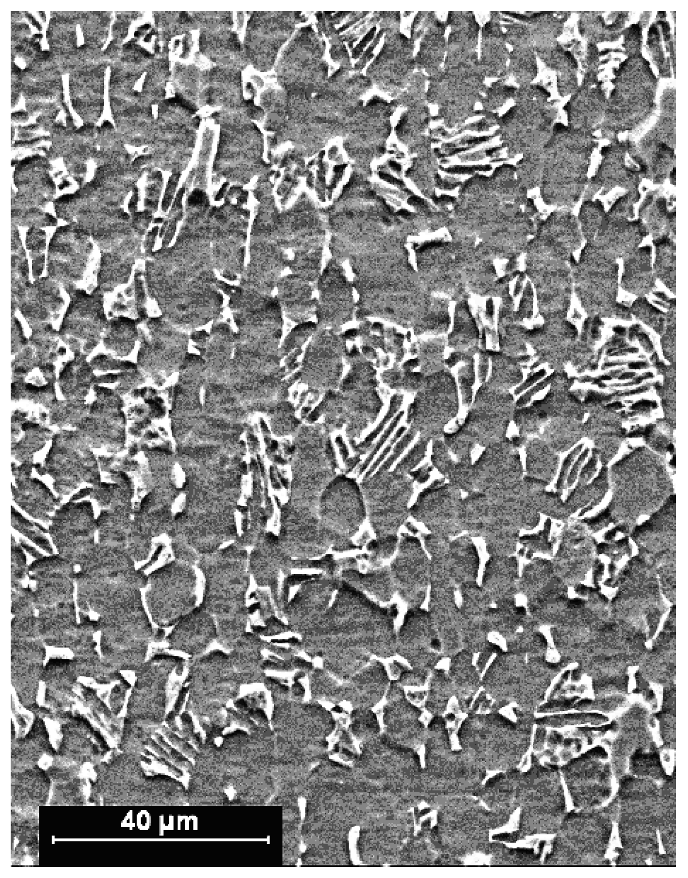
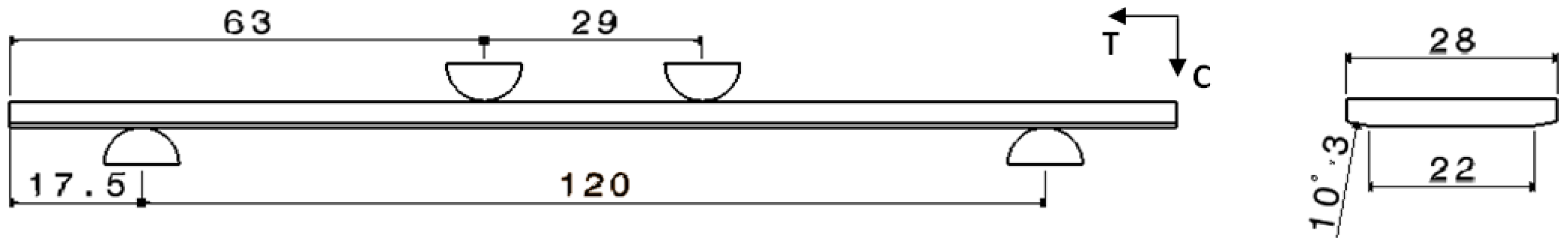
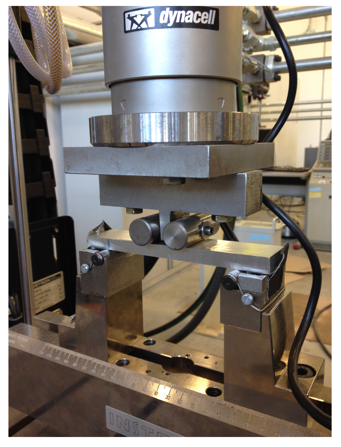
2. Material and Methods

The material studied is an α + β two-phase titanium alloy, Ti6Al4V. It is received in the form of plates that are obtained by hot rolling (1050 ° C) and followed by annealing heat treatment (730 ° C, slow cooling). Figure 1 shows the bimodal or duplex α + β microstructure. Phase α is shown in black and phase β in white. The grain size α is about 15–20 μm.
Figure 1. Microstructure of Ti6Al4V alloy studied.
Metals 05 01148 g001
The literature shows that the parameters characterising the surface condition in geometric, mechanical and metallurgical terms depend on machining parameters. These parameters are many and may interconnect. In order to determine the relations between the various machining parameters and the surface condition, it was decided to build the study on the experimental plan method. This method proves to be useful in multi-variable problems as it allows the level of significance of factors on a given response to be highlighted. A 2 6 - 2 fractional factorial design with 6 factors at 2 levels was adopted. 16 tests were conducted scanning the border of the domain studied with 4 tests more towards the centre, in total 20 tests. The factors and levels are shown in Table 1. The range of values for the cutting speed is defined by the material machined, the material of the tool and the cutter used by our industrial partner. Figure 2 shows the cutting and feed direction. The tool is also represented with nose radius, noted Rϵ. To eliminate the effect of cutter wear, a new insert was used for each test for the roughing and finishing pass. Similarly, the experimental plan does not take into account the cutter position (cutting angle, rake angle and cutting edge direction) and the nature of the cutter itself (material and coating). Processing of the experimental plan was performed using the JMP software (SAS Institute publisher, Cary, NC, USA). The test results are shown in Table 2. It is important to note that the experimental plans do nothing to explain the physical mechanisms brought into play during milling. In the present study, they are used to highlight the various determinant machining parameters for surface integrity and generate different surface conditions for fatigue testing.
Table 1. Assignment of the factor levels.
FactorsLevels
Cutting speed, V (m/min)32–100
Feed rate, fz (mm/tooth)0.1–0.2
Depth of cut in roughing, ap r o (mm)1–3
Depth of cut in finishing, ap f i n (mm)0–0.5
Nose radius, R ϵ (mm)2.5–4
LubricationYes–No
Figure 2. Schematic of face milling and tool.
Metals 05 01148 g002
Face milling was performed on a 3-axis milling machine of the HURCO brand (Indianapolis, IN, USA) with a power of 10 kW. The cutting tools used were of the ISCAR brand (Tefen, Israel) references ADKT 150524R- HM IC928 and ADKT 150540R-HM IC928, named respectively T1 and T2. These cutters are carbide grade IC928 with a PVD TiAlN coating as recommended for the machining of titanium alloys. These cutters are currently used in the aeronautical industry. The difference between the two cutters lies in the nose radius Rϵ, which is 2.5 mm for T1 and 4 mm for T2. For reasons of economy, a single cutter was mounted on the machine.
Table 2. Experimental design.
Run N ° Machining Parameters
VfzaproapfinR ϵ Lub
(m/min)(mm/tooth)(mm)(mm)(mm)
1540.1331.650.152.5N
2780.1331.650.152.5Y
3540.1331.650.354N
4780.1331.650.354Y
5540.1671.650.152.5N
6780.1671.650.152.5Y
7540.1671.650.354N
8780.1671.650.354Y
9660.1520.252.5Y
10660.1520.254N
11660.120.252.5Y
12660.220.254N
13660.1510.254N
14660.1530.252.5Y
15660.15204N
16660.1520.52.5Y
17320.1520.252.5Y
181000.1520.254N
19660.1520.252.5Y
20660.1520.254N
Fatigue failure four-point bending tests were performed on the test coupons shown in Figure 3 and Figure 4. In our case, the 4-point bending is the most suitable because it allows to study a fairly large element surface to be representative of a milled surface. Knowing that we want to highlight the effect of the surface on the fatigue lifetime. Two chamfers were used to eliminate sharp edges. To finish they were polished by hand to remove scratches from machining and the concentration of stress generated by the edges of the chamfers. They were taken from the plate so that the stress caused by four-point bending was parallel to the direction T (Figure 3). Directions T and C are perpendicular to the rolling direction. The tests were conducted at ambient temperature, with a frequency of 7 Hz and a load ratio R = 0.1. These tests explored a life cycle domain around 10 5 cycles. Each coupon was milled with a new cutter. In this study the fatigue failure criterion was used, i.e., the test was performed until failure of the specimen. The thickness of the fatigue specimen is 3.5 mm.
Figure 3. Fatigue specimens geometry (values are given in mm).
Metals 05 01148 g003
Figure 4. 4 points bending assembly.
Metals 05 01148 g004
Roughness was measured using a Mahr type Perthometer PGK120 roughness meter (Deterco, Inc., Houston, TX, USA). Three roughness criteria (ISO 4287) were considered: the arithmetic roughness Ra corresponding to the mean of the peaks and hollows in relation to the mean line and measured over an evaluation length L (Equation (1)); roughness Rt, which is the distance between the biggest peak and the biggest hollow (Equation (2)); and roughness Rz, which is the height of irregularities in mean roughness over 10 points (Equation (3)).
R a = 1 L 0 L y ( x ) d x
R t = z m a x - z m i n
R z = 1 5 i = 1 5 ( z i ) m a x + j = 1 5 ( z j ) m i n
Measurement of residual stresses (RS) was performed using the X-ray diffraction method (XRD) on a SET-X brand goniometer (Baseline, Austin, TX, USA). We used a beam vanadium. Only surface residual stresses were measured, along the feed direction. The residual stresses measured were parallel to the stress induced by the fatigue 4-point bending test. We conducted repeatability of measurements for run 1 and observed very little dispersions (Table 3). This led us in this study, to carry out only one measuring residual stress for each test.
Table 3. Measurement of repeatability of the residual streses for run 1.
MeasuresRS (MPa)
1−261
2−266
3−264
Average−263.6
As far as the metallurgical parameter is concerned, a previous study [12] had highlighted the difficulty involved in measuring microhardness with significant dispersion caused mainly by the very nature of the α + β two-phase titanium alloy material. Focusing on the microstructure, no phase change or plastic deformation under the surface was observed. However, Velasquez [13] reveals the existence of a fine hardened layer very close to the milled surface (<10–15 μm). In order to take this into account, a criterion was sought for the metallurgical parameter with the chord width (noted LC). Castex et al. [14] explain that the diffraction peak (obtained by XRD) allowing the stress condition in a given volume of material to be observed also gives data on the level of dislocations or hardening in it through the width of the diffraction peak or the chord width. The rate of dislocation or hardening increases with an increase in the chord width. Several studies have used the chord width to characterise the state of hardening in the surface, on peening for example in Hoffmeister et al. [15] or during machining in Madariaga et al. [16].
Roughness and residual stresses were used as a basis to determine the milling plans of procedure to conduct fatigue tests. To do so, it was decided to correlate low/high roughness values and low/high residual stress values in compression in order to observe their influence on the fatigue lifetime. The chord width was also taken into account. In total six milling plans of procedure were retained (Table 4). These were derived from a much broader test campaign that included 20 milling tests. Each plan of procedure was tested for two levels of loading: level 1 ( σ m a x 1 ) and level 2 ( σ m a x 2 ). These were determined in order to obtain a lifetime of between 10 5 and 10 6 cycles. For each level, two coupons were tested. In total, 24 fatigue tests were conducted.
Table 4. Measurement of parameters of surface integrity.
Specimen N°Response
RaRtRzRSLC
(μm)(μm)(μm)(MPa)( ° )
10.252.091.64−2641.819
30.563.93.13−2611.991
40.393.152.41−2921.794
120.442.92.5−1141.406
170.433.372.8−2151.282
180.63.763.3101.747

3. Results and Discussion

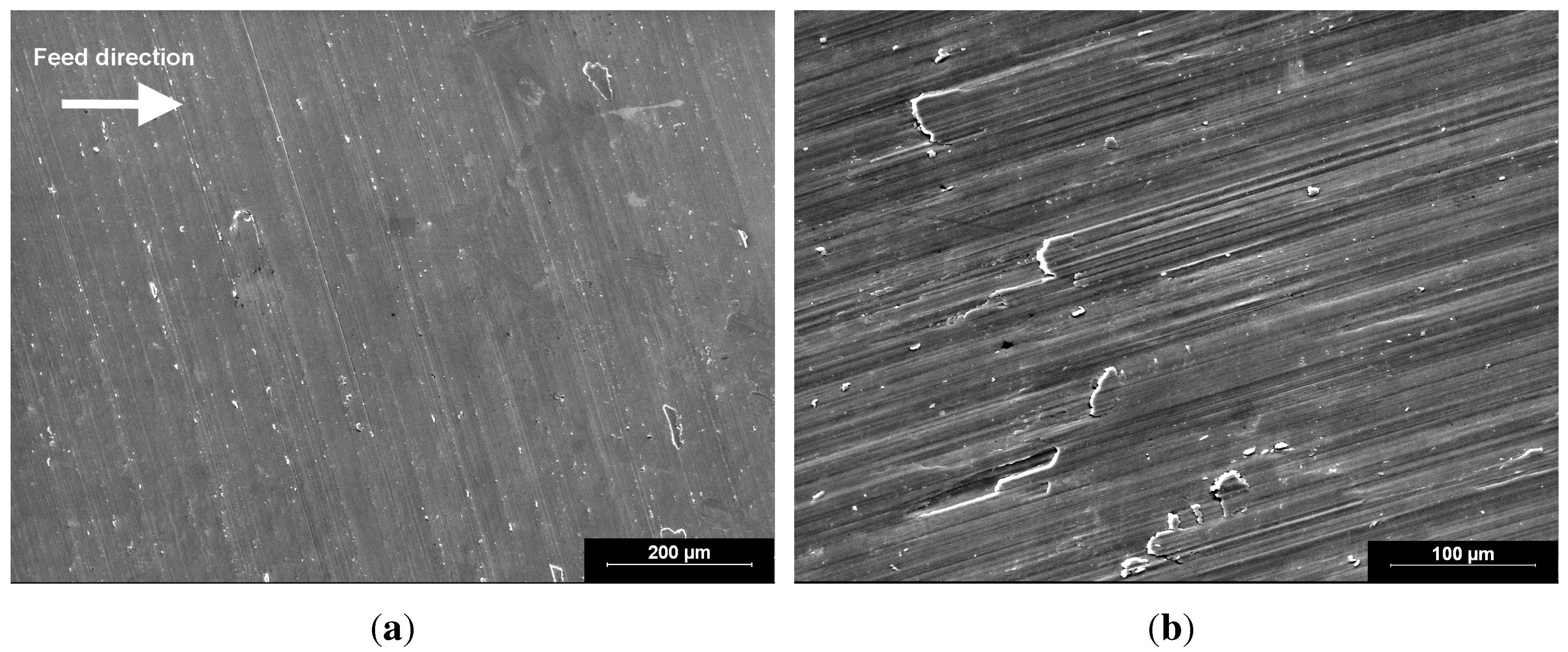
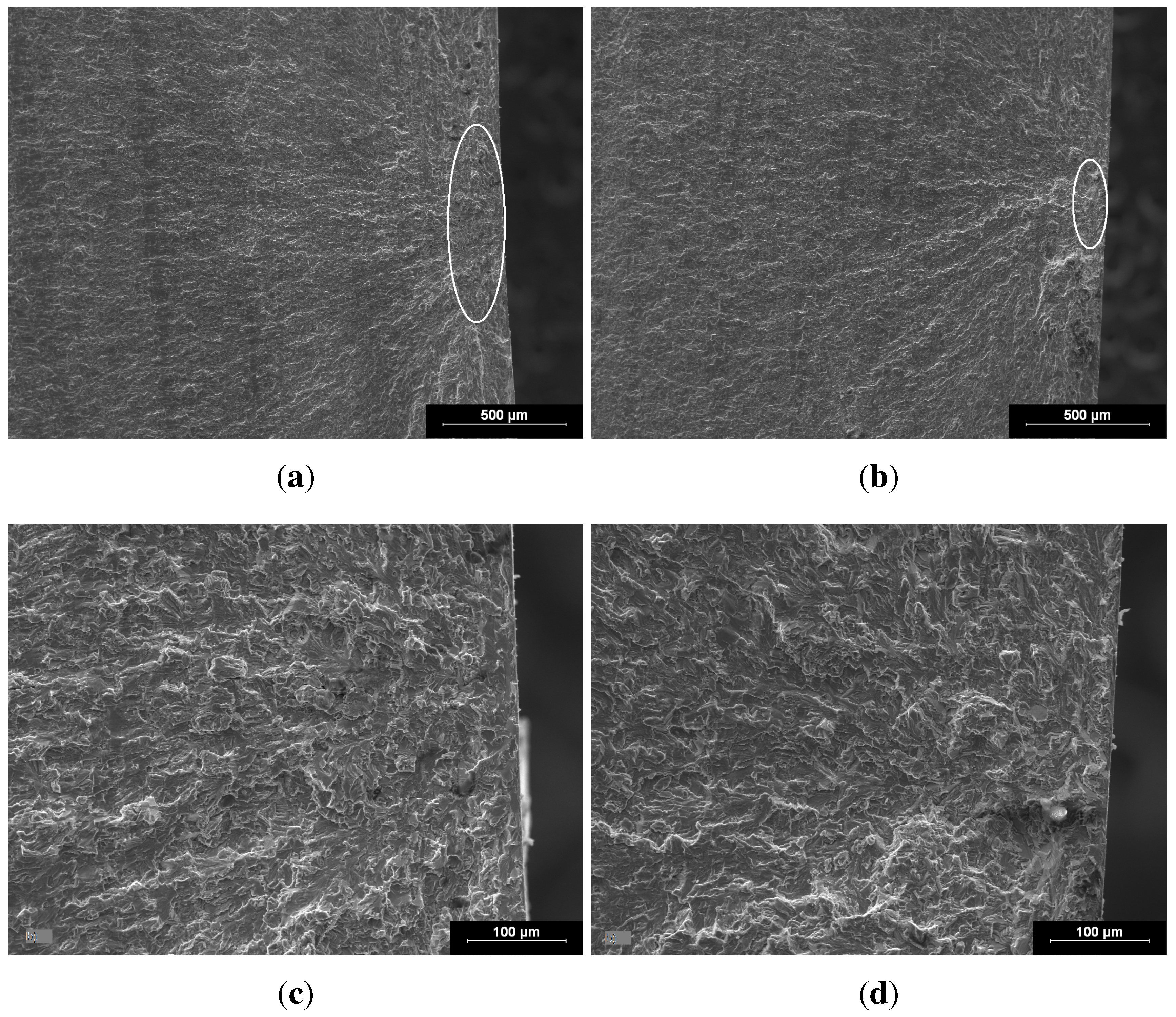
3.1. Machining/Surface Integrity

The difference of the experimental plan outcomes will be related to the three parameters defining surface integrity. An Analysis Of Variance (ANOVA) was conducted with the aim of analysing the influence of the cutting speed, feed rate and depth of pass in roughing and finishing, as also the nose radius and lubrication on surface integrity parameters.
Geometric Parameter: Machine Surface Roughness
Two main phenomena were observed on all the machined surfaces: traces of feed or deformations perpendicular to the feed direction generated by the cutter (Figure 5a) and an orange skin texture visible to the naked eye. The presence of this texture can mainly be explained by a re-deposition and crushing of the material during milling of micro-cavities and chips that adhered to the machined surface. The deformations due to feed are the result of plastic flow of the material during cutting, but can also arise from significant edge sharpness and nose radius. Micro-cavities, meanwhile, are generated by brittle failure of inclusions of carbide on the surface during shearing of the material by the cutter. Re-deposition of the material was observed on all milled surfaces during dry machining but can also appear with conventional lubrication. This phenomenon is due to fine particles of chips that become welded to the machined surface thus forming a composite surface. Indeed, milling titanium can generate high local temperatures that will facilitate the welding/adherence process. Ezugwu et al. [17] also observed those phenomenons. The temperature at the cutter/chip interface when turning a titanium alloy with a cutting speed of 200 m/min, a feed rate of 0.1 mm/rev and a carbide cutting tool can reach 1100 ° C dry and 900 ° C with conventional lubrication says Kitagawa et al. [18]. The same author also states that tool wear can also intervene in this phenomenon. In the present study, each surface was machined with a new cutter, proving that tool wear is not the triggering mechanism of the phenomenon, although it may tend to accentuate it, with re-deposition of the material producing the clearly visible orange skin effect on the machined surfaces. As in Ezugwu et al. [17] case, fine particles of chips having adhered to the milled surface can be seen. But the orange skin texture mainly derives from marks observed in traces of the feed direction. These marks are caused on milling by stretching of strips of material up to sudden failure (Figure 5b).
Figure 5. Milled surfaces. (a) Run N ° 1: V = 54 m/min, ap f i n = 0.15 mm; (b) Details Run N ° 1.
Metals 05 01148 g005
The roughness measured was between 0.25 and 0.6 μm for Ra, between 2.09 and 3.9 μm for Rt and between 1.64 and 3.31 μm for Rz. It was noted that the factor having most influence on Ra, Rt and Rz responses was R ϵ , especially for Rt and Rz where it was extremely significant. Another highly significant factor on Rt is the cutting speed, V. Experience has shown that with R ϵ fixed, an intervention is required on fz and V to alleviate roughness, whether in milling or turning. Generally, in finishing, the cutting speed is increased and feed rate diminished. As far as the most influential factor (R ϵ ) is concerned, which is common to these three responses, it can be seen that the lower it is, the more roughness will be reduced. This contradicts conventional models for roughness that indicate that Rt (μm) depends mainly on the feed rate f (mm/rev) and the nose radius R ϵ (mm): when R ϵ increases, the theoretical roughness Rt diminishes. Indeed, this result appears logical: the increase in the nose radius leads to an increase in the contact length and thus a reduction in the ridge height Rt, though this is contrary to the observations made in the present study. This may be explained by the fact that cutting is not ideal: we observed a ploughing phenomenon on the surfaces milled. Furthermore, the second pass of the tooth tended to exacerbate this effect with a non-negligible spring-back phenomenon.
Mechanical Parameter: Residual Stresses
The residual stresses measured were between 0 and −292 MPa. The most significant factor on the RS response was the cutting speed V. When this is reduced, the residual stresses tend towards compression. And as V increases, this leads to an increase in temperature and the residual stresses tend towards tension. Velasquez [13] and Sun and Guo [19] have observed this phenomenon. Brosse et al. [20] explain that it should be borne in mind that residual stresses are generated by a complex combination of thermal, mechanical and metallurgical effects. Mechanical loading generally leads to residual stresses in compression due to plastic deformation of the material on the surface and at depth during cutting. Conversely, thermal effects produce residual tensile stresses generated by significant thermal gradients. Changes in temperature generate stresses in the material by dilation and contraction phases. Meanwhile, the metallurgical effects are undistinguishable from effects of thermal origin. Obviously, when the material is subjected to increases in temperature, phase changes may occur leading to local modification of the thermal and mechanical properties and a change in the microstructure. Following these transformations, the explanation for the residual stresses obtained is complicated as these phenomena come into competition with purely thermal phenomena. In our study, a decrease of cutting speed leads to a preponderance of the mechanical effect and therefore residual stresses are compressive. Conversely, an increase in the cutting speed leads to a preponderance of the heat effect (increase in temperature) and therefore the residual stresses are tensile. In the present case, this temperature increase is not significant enough to cause a phase change.
Metallurgical Parameter: Chord Width
The chord width measured was between 1.282 ° and 1.991 ° . The most significant factor on the chord width response was lubrication, which tended to reduce it. Lubrication is known to play a number of roles during machining. The first is in improving sliding at the cutter/material interface, which generally leads to reducing cutting forces. Reducing the latter can lead to a reduction in hardening and thus in the chord width. The second role is in cooling the cutting zone, which can in turn lead to an increase in hardening and thus in the chord width. In the present instance and in light of current knowledge, it remains impossible to privilege one or other phenomenon. To a lesser extent, the pass depth in finishing apfin also has an effect on chord width, since when it increases, the latter diminishes. This may suggest a predominance of the thermal effect since there is a section of the chip that increases with apfin, and thus an increase in cutting forces and temperature. To conclude, it can be said that the thermal effect leads to a softening and the mechanical effect leads to hardening of the surface. This was observed by Ginting and Nouari [21] as also by Hughes et al. [22].

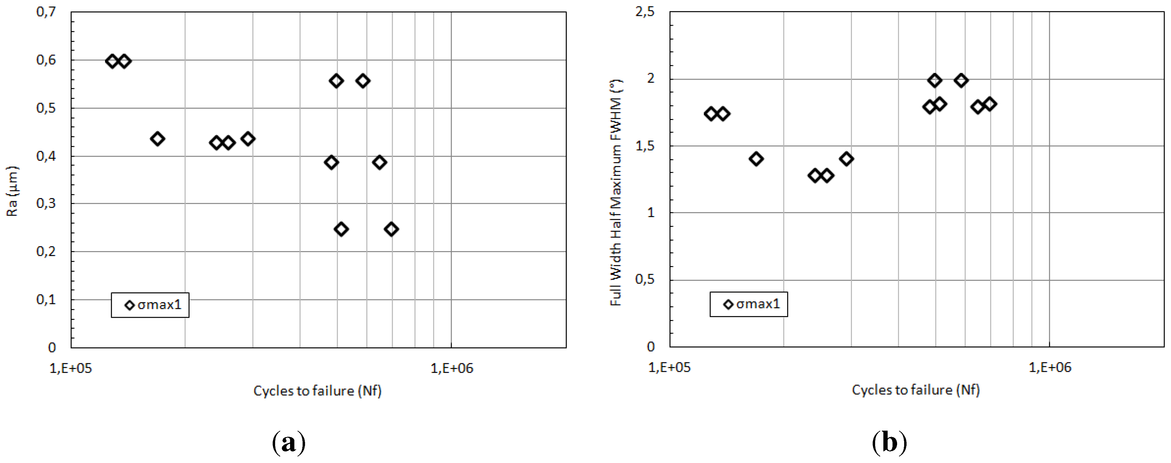
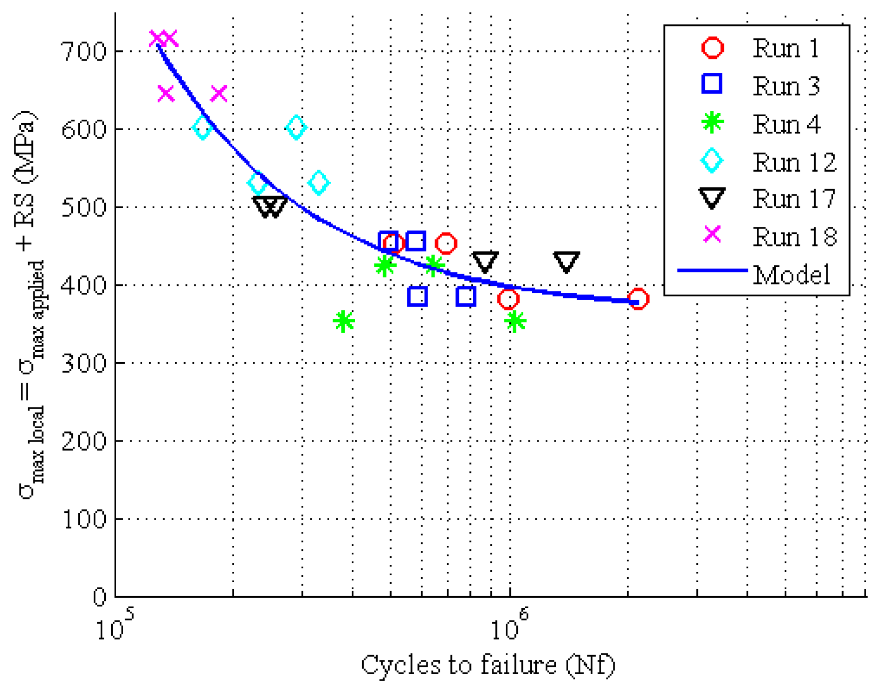
3.2. Surface Integrity/Fatigue Life

No significant influence of roughness Ra on the fatigue lifetime was observed (Figure 6a). Surfaces with high levels of roughness generated long fatigue lifetimes and for widely differing roughness values very close fatigue lives were also seen. The same observation can be made for Rz and Rt. These results suggested a priori that roughness is not influential on the fatigue lifetime in the present instance other surface finish requirements may have to be explored. As for the chord width (LC), there was no observation of a significant effect on the fatigue life (Figure 6b).
Figure 6. Roughness (a) and chord width (b) depending on the fatigue life time to σ m a x 1 .
Metals 05 01148 g006
Conversely, the effect of residual stresses seems to have a preponderant effect on lifetime. Indeed, the more parts are subject to compression the better the lifetime. Pursuing this hypothesis, it was considered that the maximum local stress ( σ m a x l o c a l ) on the surface could be a good indicator of the effect of the residual stresses. This stress is defined as follows:
σ m a x l o c a l = σ m a x a p p l i e d + R S
Measurement values for the residual stresses result from the integral value of stresses over a depth of about 30 μm (depth of penetration of the X-rays). The maximum local stress will correspond to the estimated loading on the volume of material corresponding to that depth.
Figure 7 shows the evolution of this stress corrected according to the fatigue lifetime. A regrouping of all the experimental points on a curve can be seen whatever the milling plan of procedure they represent. It can also be seen that an asymptote emerges around 380 MPa. A power type law (Equation (5)) allows this evolution with low dispersion to be described (R 2 = 0.85). Nf is the number of cycles to failure.
σ m a x l o c a l = 1 . 535 × 10 8 N f - 1 . 105 + 362 . 2
Figures 8 shows the fracture morphology, observed under the SEM (Philips XL30 ESEM, MNX, Reston, VA, USA), for two milling plans of procedure: run 1 (Figure 8a) long lifetime and run 18 (Figure 8b) short lifetime. On the fractographies, the stage I initiation zone delimited by the white ellipse can be distinguished. Stage I is characterised by splitting facets indicating brittle failure (Figure 8c,d). Stage II also corresponds to splitting. It can be seen that the initiation zone is bigger for the longer lifetimes (high compression residual stresses) than for shorter lifetimes (low compression residual stresses). No displacement of the zone of initiation at depth was observed in the long and short lifetimes. The breakage mechanisms are the same for all the fatigue test coupons, that is very close to the surface.The compressive residual stress change qualitatively and quantitatively the propagation stage I crack.
Figure 7. RS depending on the fatigue life time: σ m a x l o c a l = σ m a x a p p l i e d + R S .
Metals 05 01148 g007
Figure 8. Fracture morphology for σ m a x 1 : observation stage I and II. (a) Run 1; (b) Run 18; (c) Details Run 1; (d) Details Run 18.
Metals 05 01148 g008
According to the state of the (compressive or tensile) residual stresses, they can either enhance or diminish the fatigue lifetime. Indeed, the test coupons with higher compression residual stresses are associated with the longest fatigue lifetimes. This phenomenon has been observed in Javidi et al. [7] and in Smith et al. [23].
As far as the present study is concerned, residual stresses can modify the speed of propagation of cracks and/or local loading that is often considered to be an average stress.
Over long lifetimes, the initiation period practically overlaps with the lifetime of the coupons (90% of the part’s lifetime) [2]. This is the present case and residual stresses generated by machining will mainly have an effect on initiation of cracks. This will mainly involve a local lowering effect of the mean load. For example a specimen with compressive residual stress of −300 MPa at the surface generated by the machining wil be subjected to a surface a stress of 400 MPa when a load of 700 MPa is applied to it locally.
For short lifetimes, however, the initiation period is short in relation to the propagation period. Propagation models will generally be more appropriate to describe the lifetime. In this case, for the residual stresses to act they need to slow down propagation of the crack, which is also what is observed in the tests. The effect of the mean load also exists in this instance, but the period of propagation of the crack in the zone subjected to compressive stresses will have to be distinguished from the deeper zone where they disappear.
The descriptive model proposed is global for the entire amplitude of lifetimes explored and has to be refined to better describe the switch from short to long lifetimes.

3.3. Machining/Fatigue Life

In previous results, the impact of machining parameters on surface integrity and the ensuing influence of this latter characteristic on fatigue life was highlighted. Surface integrity is largely determined by residuals stresses. Such stresses must be in compression and have high values to boost the fatigue lifetime. This raises the question as to how to select machining parameters with a view to improving fatigue life. The objective is thus to determine the cutting conditions generating the most compressive residual stresses possible. The experiment conducted showed that a low cutting speed (V) and low feed rate (f) with a small nose radius (Rϵ) accompanied by lubrication give the best results. This is represented by the plan of procedure Optim1. Meanwhile, the depth of pass appears to have little influence on the RS and it was therefore decided to take a high value to increase the amount of material removed and to just make one machining pass (without finishing). Indeed, it was noted in a previous study [12] that high pass depths had little or no influence on microhardness and plastic deformations under the machined surface. These conditions were compared with industrial applications that were taken to be the reference. These are shown in Table 5 as well as roughness responses (Ra, Rt and Rz) and residual stresses. It was previously noted that the chord width does not influence the fatigue life. It has therefore not been presented. Roughness, meanwhile, remains a criterion to define the quality of a surface and is used in design offices. Tests were conducted using five teeth so as to compare with industrial conditions. Optim2 had the same cutting conditions as Optim1 apart from the nose radius where it was decided to use the reference plan of procedure (R ϵ = 6.2 mm). The goal was to see its influence on roughness and residual stresses. The reference plan of procedure was conventional, as used in the aviation industry for titanium alloy milling operations, involving both roughing and finishing stages. The results for loading σ m a x 1 are shown in Figure 9.
Table 5. Cutting conditions and responses for the Ref and optimized plan of procedure.
ProcedureMachining ParametersResponse
VfzaproapfinR ϵ RaRtRzRS
(m/min)(mm/tooth)(mm)(mm)(mm)(μm)(μm)(μm)(MPa)
RefRo500.13/6.21.065.95.22−159
Fin600.1/0.56.2
Optim1320.1/3.52.51.146.525.51−297.5
Optim2320.1/3.56.20.84.754.2−242.5
Figure 9. Comparison between optimized and Ref procedure for σ m a x 1 .
Metals 05 01148 g009
Firstly, it can be seen that using five teeth leads to increasing roughness by a factor of 2 as compared with the tests in the experimental procedure (Table 5). The proposed model is valid over a range of roughness values set by the experimental procedure. The roughness values measured for the additional tests (Optim1 and Optim2) are outside this range but this in no way detracts from the quality of the model. Furthermore, residual stresses were about twice as great for the Optim1 and Optim2 as compared with the reference plan of procedure. It should be noted that despite close residual stress values (−297.5 MPa for Optim1 and −242.5 MPa for Optim2), the lifetimes obtained were very different. This can partly be explained by the far from negligible uncertainty on measurements of residual stresses for Optim2. In conclusion, it can be seen that the best lifetimes were generated by the machining plan of procedure of Optim1. For example, for loading σ m a x 1 , the fatigue life for plan of procedure Optim1 was improved by a factor of 2.7 as compared with the reference industrial plan of procedure. This result is especially significant. The hypothesis of the model, as defined previously, taking into account the residual stresses in the load applied, correctly describes the fatigue behaviour despite roughness multiplied by two and a pass with five teeth.

4. Conclusions

Firstly the milling/surface condition relation was established and the impact of machining parameters (V, fz, R ϵ , ap and lubrication) on surface integrity was observed. Then, the influence of surface integrity on fatigue lifetime was studied. Finally, a machining plan of procedure was proposed to improve fatigue lifetime. This plan of procedure was devised to generate high compressive residual stresses. Studying the milling/surface relation allowed cutting conditions favouring this stress condition to be privileged, with moderate cutting speed and feed rate, a small nose radius and the use of lubrication. As the depth of pass meanwhile proved not to be significant and in order to improve productivity, a high value was adopted, being equivalent to that used in industrial plans of procedure. The optimised machining plan of procedure allowed for the fatigue lifetime to be improved by a factor of 2.7 as compared with a reference industrial plan of procedure. The phenomenological model correctly described fatigue behaviour.

Author Contributions

K. Moussaoui, M. Mousseigne, J. Senatore and R. Chieragatti conceived and designed the experiments; K. Moussaoui performed the experiments; K. Moussaoui, M. Mousseigne, J. Senatore and R. Chieragatti analyzed the data; P. Lamesle contributed of X-ray diffraction tool; K. Moussaoui wrote the paper.

Conflicts of Interest

The authors declare no conflict of interest.

References

  1. Ezugwu, E. Key improvements in the machining of difficult-to-cut aerospace superalloys. Int. J. Mach. Tools Manuf. 2005, 45, 1353–1367. [Google Scholar] [CrossRef]
  2. Novovic, D.; Dewes, R.C.; Aspinwall, D.K.; Voice, W.; Bowen, P. The effect of machined topography and integrity on fatigue life. Int. J. Mach. Tools Manuf. 2004, 44, 125–134. [Google Scholar] [CrossRef]
  3. Alam, A.M. Influence de Gammes de Tournage sur l’état de Surface et la Fatigue en Endurance limitée D’un Acier de Construction. Ph.D. Thesis, University Paul Sabatier de Toulouse, 1998. [Google Scholar]
  4. Suraratchai, M. Influence de l’état de Surface sur la Tenue en Fatigue de L’alliage D’aluminium 7010. Ph.D. Thesis, University Toulouse III - Paul Sabatier, 2006. [Google Scholar]
  5. Geng, G.S.; Xu, J.H. Surface Integrity and Fatigue Property of a High Speed Milled Titanium Alloy. Adv. Mater. Res. 2008, 53–54, 305–310. [Google Scholar] [CrossRef]
  6. Sasahara, H. The effect on fatigue life of residual stress and surface hardness resulting from different cutting conditions of 0.45%C steel. Int. J. Mach. Tools Manuf. 2005, 45, 131–136. [Google Scholar] [CrossRef]
  7. Javidi, A.; Rieger, U.; Eichlseder, W. The effect of machining on the surface integrity and fatigue life. Int. J. Fatigue 2008, 30, 2050–2055. [Google Scholar] [CrossRef]
  8. Ghanem, F.; Fredj, N.B.; Sidhom, H.; Braham, C. Influence du mode de fraisage sur l’intégrité de surface et la tenue en fatigue des pieces usinées. In 22eme journes de Printemps - Fatigue et procédés de Fabrication, ed. S. F. D. M. E. MATERIAUX. CETIM; 2003. [Google Scholar]
  9. Li, W.; Guo, Y.B.; Barkey, M.E.; Jordon, J.B. Effect Tool Wear During End Milling on the Surface Integrity and Fatigue Life of Inconel 718. Procedia CIRP 2014, 14, 546–551. [Google Scholar] [CrossRef]
  10. Yao, C.F.; Wu, D.X.; Jin, Q.C.; Huang, X.C.; Ren, J.X.; Zhang, D.H. Influence of high-speed milling parameter on 3D surface topography and fatigue behavior of TB6 titanium alloy. Trans. Nonferrous Metals Soc. China 2013, 23, 650–660. [Google Scholar] [CrossRef]
  11. Bentley, S.A.; Mantle, A.L.; Aspinwall, D.K. The effect of machining on the fatigue strength of a gamma titanium aluminide intertmetallic alloy. Intermetallics 1999, 7, 967–969. [Google Scholar] [CrossRef]
  12. Moussaoui, K.; Mousseigne, M.; Senatore, J.; Chieragatti, R.; Monies, F. Influence of milling on surface integrity of Ti6Al4V-study of the metallurgical characteristics: Microstructure and microhardness. Int. J. Adv. Manuf. Technol. 2013, 67, 1477–1489. [Google Scholar] [CrossRef]
  13. Velasquez, J.D.P. Etude des copeaux et de l’intégrité de surface en usinage a grande vitesse de l’alliage de titane TA6V. Ph.D. Thesis, University Paul Verlaine, Metz, 2007. [Google Scholar]
  14. Castex, L.; Lebrun, J.L.; Maeder, G.; Sprauel, J.M. Détermination des Contraintes Résiduelles par Diffraction des Rayons X; Number 22 in Publications Scientifiques et Techniques—Ecole Nationale Supérieure D’arts et Métiers; ENSAM: Paris, France, 1981. [Google Scholar]
  15. Hoffmeister, J.; Schulze, V.; Hessert, R.; Koenig, G. Residual stresses under quasi-static and cyclic loading in shot peened Inconel 718. Int. J. Mater. Res. 2012, 103, 66–72. [Google Scholar] [CrossRef]
  16. Madariaga, A.; Esnaola, J.A.; Fernandez, E.; Arrazola, P.J.; Garay, A.; Morel, F. Analysis of residual stress and work-hardened profiles on Inconel 718 when face turning with large-nose radius tools. Int. J. Adv. Manuf. Technol. 2014, 71, 1587–1598. [Google Scholar] [CrossRef]
  17. Ezugwu, E.O.; Bonney, J.; Da Silva, R.B.; Cakir, O. Surface integrity of finished turned Ti-6Al-4V alloy with PCD tools using conventional and high pressure coolant supplies. Int. J. Mach. Tools Manuf. 2007, 47, 884–891. [Google Scholar] [CrossRef]
  18. Kitagawa, T.; Kubo, A.; Maekawa, K. Temperature and wear of cutting tools in high-speed machining of Inconel 718 and Ti-6Al-6V-2Sn. Wear 1997, 202, 142–148. [Google Scholar] [CrossRef]
  19. Sun, J.; Guo, Y. A comprehensive experimental study on surface integrity by end milling Ti-6Al-4V. J. Mater. Process. Technol. 2009, 209, 4036–4042. [Google Scholar] [CrossRef]
  20. Brosse, A.; Hamdi, H.; Bergheau, J.M. A numerical study of phase transformation during grinding. Int. J. Mach. Mach. Mater. 2009, 4, 148–157. [Google Scholar] [CrossRef]
  21. Ginting, A.; Nouari, M. Surface integrity of dry machined titanium alloys. Int. J. Mach. Tools Manuf. 2009, 49, 325–332. [Google Scholar] [CrossRef]
  22. Hughes, J.I.; Sharman, A.R.C.; Ridgway, K. The Effect of Cutting Tool Material and Edge Geometry on Tool Life and Workpiece Surface Integrity. Proc. Inst. Mech. Eng. B J. Eng. Manuf. 2006, 220, 93–107. [Google Scholar] [CrossRef]
  23. Smith, S.; Melkote, S.N.; Lara-Curzio, E.; Watkins, T.R.; Allard, L.; Riester, L. Effect of surface integrity of hard turned AISI 52100 steel on fatigue performance. Mater. Sci. Eng. A 2007, 459, 337–346. [Google Scholar] [CrossRef]

